1
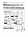
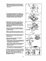
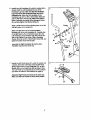
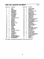
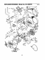
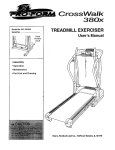
65O
B
,Iner
USER'S M_
Model No+83t,285370
Write the sedal nunlber in the
spaoe above for future referenGe,
Number
E_
u
_/_'/
IF,_
ENT
HELPLINEI
1-800+736-6879
SEARS, ROEBUCK AND CO.,
HOFFMAN ESTATES, IL 60179
www.proform.com
new products, prizes,
fitness tips, and much morel
iner
650
T_LE _
CONiNg:
IMPG_T
PREGAUTIONS .............................................................
BEF_R_EYOU BEGIN ...................................................................
A_BLY
........................................................................
HOW TO USE THE ELL PT GAL GR_- 8TR/_;_INEI_.............................................
MAINT_NANGE AFID_OUBLESH(_O'_IN_
.................................................
CONOI_FJONINGGUIDELINES ............................................................
PA_T UST ...............................
........
. ................
.......................
F-.X'P
:I:I2ODEO
DRAWING ..................................................................
HOW TO ORI_R'R_aLA_EMEh_fi ":PARTS ,.. ; ..........
-...........................
FULL g0 DAY WAR_TY
. .............................................
3
4
5
9
12
13
14
15
flaGk Cover
Ba_k Cover
3
BEFORE YOU BEGIN
Congratulationsfor selecting the new PROFORM •
650 CARDIO CROSSTRAINER. The PROFORM ° 650
is an Incrediblysmoothexerciser that moves your feet
in a natural ellipticalpath, minimizingthe impact on
your knees and ankles.And the unique PROFORM °
650 features adjustable resistanceand a state-of-theart consoleto helpyou getthe mostfrom your axerrise. Welcome to a whole new wodd of natural, elliptical-motionexercise from PROFORM.
after readingthe manual, please call our toll-frae
HELPLINE at 1-800-736-6879, Monday through
Saturday. 7 a.m. until7 p,m. Central Time (excluding
holidays).To help us assistyou, please note the product modelnumber and sadal number before calling.
The model number is 831.285370, The sedal number
can be found on a decal attached to the alfiptical
crosstratner(see the frontcover of this manual for the
locationof the decal).
For your benefit, read this manual carefully before
you use the PROFORM° 650. If you have questions
Before readingfurther,please familiadze yourselfwith
the pads that are labeled in the drawingbelow.
Handlebar
ResistanceKnob
Console
Bookrack
Heart Rate Sensor
Console Handgdp
FRONT
Pedal
BACK
Wheel
Pedal Disk
Pedal Spdng
LEFT SIDE
*No water bottle
is included
4
ASSEMBLY
Assembly requires two persons. Place all parts of the ellipticalcrosstralnerin a cleared area and remove the
packing materials. Do not dispose of the packing materialsuntil assembly is completed. In addition to the
Included allen wrenches, assembly requlrss a phillips screwddver (_,
an adjustable
wrench (_=_,
and a rubber mallet C_)
•
As you assemble the ellipticalcrosstreiner0use the drawingsbelow to Identifythe small parts used In assembly.
The number in parenthesisbelow each drawingrefers to the key number of the part, from the PART LIST on
page 14. The second number refers to the quantify used in assembly.Note: Some small parts may have been
pre-aseemblad for shipping. If s part Is not In the parts bag, check to see If It has been pre-asserobled.
@8 @@
M8 Nylon
Locknut (38)-4
M10 Nylon
Locknut (33)-6
M10 Splk
Washer (45)-2
Console
Screw (59)-4 M8 x 19mm Button
M10 x 27ram
Screw (56)-2
PatchScrew(40)-2
Handlebar
Washer (55)-2
M10 x 27rom
Carriage Bolt(27)-2
M 10
Washer (29)-2
Spdng Bracket
Washer (35)-2
M10 Bolt Bet (25)-2
M8 x 45mm ButtonBolt (50)-4
M10 x 75rom Carriage Bolt (34)-4
M10 x 74mro Bolt (7)-2
1. Identifythe Front Stabilizer(10), whichhas round
Endceps (21) on it. While another parson lifts the front
of the Frame (1), attach the Front Stabilizer to the
Frame with two MIO x 75mm Carriage Bolts(34) and
two M10 Nylon Locknuts (33).
5
2. While another person lifts the back of the Frame (1),
attach the Rear Stabilizer (9) to the Frame with two
M10 x 75mm Carriage Bolts (34) and two M10 Nylon
Locknuts (33).
3. The Console (23) requiresthree "AA"batteries(not
included);alkaline batteriesare recommended.Insert
three batteries intothe battery compartment.Make
sure that the batteries are oriented as shown by
the diagram Inside the battery compartment.
4. While another person holdsthe Console(23) in the
position shown, insertthe control cable and the console wire down through the Upright(2). Attach the
ground wire to the Uprightwith an M4 x 16ramSerftapping Screw (52). Insert the excess cable and wire
into the Updght.
3
4
----=-Battedes
n
e W;r
oo o,
Attach the Console (23) to the Upright(2) with four
Console Screws (59). Be careful to avoid pinching
the cable and wires.
Make sure the Resistance Knob (42) is set on the
lowest setting before proceeding to the next step.
5. While another person holds the Upright(2) In the position shown, connect the console wire to the Reed
Switch Wire (53).
Next, connectthe controlcable to the Resistance
Cable (43) in the followingway:.
Ground 5_/_
_59COntrOlCab'_
' _
e
°
Makeeu the
\
\
\
\
45
33 j*'_
"-_-_
• Refer to drawingA. Pull up on the metalbracket, and
insert the tip of the control cable Intothe wire clip on
the Resistance Cable (43) as shown.
• Refer to drawing B. Firmly pull the controlcable and
elide it into the metal bracket on the Resistance
Cable (43) as shown.
_ .,___.___7
, .".er._
_ i -Control t
Cable-" "_ _console
43"_
Wires and
Cables do not
get pinched and
damaged during
this step.
C_53
• Refer to drawingC. Using pliers, squeeze the prongs
on the upper end of the metal bracket together.
Push the excess cable and wires down intothe Frame
(1). Insert the Upright(2) Into the Frame. Do not pinch
the wires or cables. Secure the Upright to the Frame
with two M10 x 74mm Bolts(7), two M10 Split
Washers (45), and two M10 Nylon Locknuts (33). Do
not tighten the Bolts yet.
6
Control"_
Cable "-_ ' ' _-
Bracket
Metal _j
Cable !
Control
43-I
;_
Cable
Control
'1
6. Identifythe Left Handlebar (6), which is marked with a
sticker. Insert the Left Handlebar intoone of the
Handlebar Legs (5); make sure that the Handlebar
Leg Is turned so the hexagonal holes are on the
Indicated side. Attach the Left Handlebar to the
Handlebar Leg with two M8 x 45ram ButtonBolts(50)
and two M8 NytonLocknuts(38). Make sure that the
Nylon Locknuts are Inside of the hexagonal holes.
Do not fully tighten the Button Bolts yet,
Apply a small amount of the includedgrease to the left
and right axles on the Updght (2).
Make sure that there are two Small Handlebar
Bushings(49) in the Left Handlebar (6). Carefullyslide
an UprightSpacer (48), a Handlebar Spacer (47), the
Left Handlebar,and a HandlebarCap (46) ontothe left
axle on the Upright(2) as shown. Slidea Handlebar
Washer (55) onto an M8 x 19ramButtonScrew(56), and
tightenthe ButtonScrew intothe axle.
55
56
Assemble the Right Handlebar (5) and the other
Handlebar Leg (5) in the same way.
7. Identify the left Pedal Spring (11), which is marked with
a sticker.Attach the Left Pedal (13) to the left Pedal
Spdng with an M10 x 27mm Pedal Bolt(27), an M10
Washer (29), and a Pedal Knob (28) as shown, Note:
The Left Pedal can be attached in any of five positions
(see HOW TO ADJUST THE PEDALS on page 9).
Attach the Right Pedal (not shown) In the same way.
Make sure that both Pedals are in the same position,
28
7
8. Apply a small amount of grease to the axle on the left
Disc Crossbar(16). Slide a Spdng Spacer (63) onto the
axle; make sure that (he Spring Spacer ta turned so
the fiat aide Is facing the elliptical oroaatralner.
Next, slidethe Left Rear Spdng Bracket(12) on the left
Pedal Spdng (11) onto the axle. Slide a SpringBracket
Washer (35) onto an M10 x 27ram Patch Screw (40),
and tightenthe Patch Screw intothe axle.
Next, hold the lower end of the left Handlebar Leg (5)
inside of the Front Spdng Bracket (65) on the left Pedal
Spdng (11). Apply grease to an M10 BoltSet (25).
Attach the Handlebar Leg to the Front Spdng Bracket
with the Bolt Set. Do not overtlghtan the Bolt Sat;
the Handlebar Leg must pivot freely.
7"
40
35
Attach the dght Pedal Spdng (cot shown)to the right
side of the ellipticalcrosstralnerin the same way.
Grease
Refer to step 5. Tighten the M10 x 74ram Bolts(7) in
the Updght (2).
16
65
11
Refer to step 6. Tighten the M8 x 45mm ButtonBolts
(50) in the Handlebar Legs (5).
9. Make sure that all parts of the elliptical crosstrainer are propedy tightened. Note: Some hardware may
be left over after assembly is completed.To protectthe floor _ carpet from damage, place a mat under the
ellipticalcrosstralner.
8
HOW TO USE THE ELLIPTICAL CROSSTRAINER
HOW TO ADJUST THE RESISTANCE OF THE
PEDALS
As you exercise,
you can adjust
the resistanceof
the pedals with
the resistance
knob on the
dght side of the
console.To
increase the
resistance,
turnthe knob
clockwise;to
decrease the
resistance,tum
the knob counterclockwise.The
number in the
resistancewindow displaysthe
resistance level.
Window
HOW TO ADJUST THE PEDALS
The motionof
the elliptical
crosstraineris
determinedby
the positionof
the pedals.
To adjustthe
pedals, first
loosen the pedal
knobsbeneath
the pedals, Slide
the pedalsforward or backward to one of
Pedal
the five poslKnob
tions,end then
rettghten the
knobs. Make
sure that both pedals are in the same position.
HOW TO USE THE HANDLEBARS
The handlebars are
designed to add
upper-body exercise to your workouts. As you exercise, push and pull
the handlebars to
work your arms,
shoulders,and
back.
andlebars
Console
Handgdp
To exerdse only your_wer bod_ hold theconsole
handgdp as you exercise.
HOW TO EXERCISE ON THE ELUPTICAL
CROSSTRAINER
To mountthe
ellipticelcrosstrainer, holdthe
Console
console handgdp and step
onto the pedal
that is in the
lowest position.
Then, step onto
the other pedal.
Push the pedals
until they begin
to move with a
continuous
motion.Note:
The pedal
disks ran turn
in either direction. it Is recommended that you move the pedal disks In the
direction shown by the arrow; however, for vadaty,
you may turn the pedal disks In the opposite direction,
To dismountthe ellipticalcrosstrainsr, wait untilthe
pedals come to a complete stop. (Note: The elllptlcel
crosstralner does not have a free wheal; the pedals will continue to move until the flywheel stops.)
When the pedals are stationary,step off the highest
pedal first.Then, step off the lowest pedal.
FEATURES
OFTHECONSOLE
HOW TO OPERATE THE CONSOLE
Make surethat there are battedes in the console (see
assemblysteps 3 and 4 on page 6). If there is a thin
sheet ofdear plastic on the console,remove it.
Followthe steps below to operate the console.
oPTla
HaAAT
M_TI
1. To turnon the power, press the On/Reset button or
simplybegin pedalling. When the power is turned
on, the entire display will appear for two seconds.
The consolewill then be ready for operation.
Heo_
2. Select one of the seven modes:
ONIRE_'_r
_
mSPt'AY
MOOI_;::
Scan mode--Mode Indicators
When the power is
turned on, the
scan mode will
automaticallybe
selected.The scan
indicatorwill
appear in the display to show that
the scan mode is selected, and a second mode
indicatorwill show which mode is currentlydisplayed. Note: If a differentmode is selected,you
can select the scan mode again by repeatedly
pressingthe Display Mode button.
The eeay-to-use console features seven modes that
provide instantexercise feedback dudngyour workouts.The modes are describedbelow.
Speed--This mode displaysyour pedallingspeed.
"lime--This mode displaysthe elapsed time. Note: If
you stop pedallingfor ten secondsor longer,the time
mode will pause.
Distance---This mode displaysthe distanceyou have
pedalled.
Speed, time, distanse, calories,
or fat calories
mode-To select
one of these
modesfor continuous display,press
the Display Mode
buttonrepeatedly
until onlythe MPH (or IOn/H), Time, Miles (or Kms),
Cals., or Fat Cels. indicatorappears In the display.
Make sure that the Scan indicatordoes not appear.
Calories---This mode displays the approximate number of calories you have burned.
Fat Calories---This mode displaysthe approximate
number of fat cetodes you have bumed (see FAT
BURNING on page t3).
Scan--This mode displays the speed, time, distance,
calorie, and fat celode modes, for a few seconds
each, in a repeatingcycle.
Heart Rate--This mode shows your heart rate when
you use the heart rate sensor.
To resetthe displayat any time, pressthe On/Reset
button.
Note: The console can displayspeed and distancein
either miles or kilometers.To changethe unitof measurement, hold down the On/Reset buttonfor a few
seconds. The mode indicatorswillshowwhichunitof
measurementis selected.When the batteriesare
replaced, it may be necessaryto raselect the desired
unit of measurement.
10
3. Measure your heart rate, if desired.
To measure your
heart rate, stop
pedalingand
place your thumb
on the heart rate
sensoras shown.
Do not press too
hard, or the circulation In your
thumb will be restricted, and your pulse will not
be detected. After a few seconds,the heart-shaped
indicatorin the displaywill flash steadily, two dashes willappear, and then your heart rate will be
shown. Hold your thumb on the heart rate sensor
for another 15 secondsfor the mostaccurate reading. If the displayedhead rate appears to be too
highor too low, or if your heart rate is not displayed,
liftyour thumb offthe heart rate sensor and allow
the displayto reseL Then, place your thumb on the
heart rate sensoras describedabove.
Make sure that you are applyingthe properamount
of pressureto the heart rata sensor.Try the heart
rate sensorseveral timesuntilyou become fsmllk_r
with it. Remember to stand stillwhUemeasuring
your heart rate.
4. To turnoff the power, simplywait for a few minutes.
The console has an "auto-off" feature. If the
pedals are not moved and the On/Reset button
Is not pressed for • few minutes, the power will
turn off automatically to conserve the betfedes.
11
MAINTENANCE
AND TROUBLESHOOTING
Inspectand tightenall partsof the ellipticalcrosstralner
regulady. Replace any worn parts immediately.
To clean the ellipticalcrosstrainer,use a damp cloth
and a small amountof milddetergent. Important:
Keep liquids away from the console and keep the
console out of direct sunlight. During storage,
remove the batteries from the console,
Next, refei"to the drawingbelow and Iocetethe Reed
Switch (53). Loosen,but do not remove,the indicated
M4 x 16ramSelf-tappingScrew (52). Slide the Reed
Switchslightlytowardor away from the Magnet(58) on
(he flywheel, Reltghtanthe Screw. "rumthe leftPedal
Disc (15) for a moment. Repeat untilthe console displays correctfeedback.When the Reed Switchis correctlyadjusted,reattach the Side Shields (3, 4), the
rightPedal Disc (15), and the Pedal Springs(11).
BATTERY REPLACEMENT
If the Console displaybecomes dim, the battedas
shouldbe replaced. Refer to assemblysteps 3 and 4
on page 6 for replacement instructions.
HOW TO ADJUST THE REED SWITCH
If the consoledoes not displaycorrectfeedback, the
reed switch shouldbe adjusted.To do this, you must
remove the Pedal Spdngs 111),the dght Pedal Disc
(15), and the Side Shields (3, 4). Refer to step 8 on
page 8 and remove the Pedal Spdngs.
52
HOW TO ADJUST THE DRIVE BELT
If you can feel the pedals slip while you are pedaling,
even when the resistanceis adjusted to the highest
level, the Ddve Belt (19) may need to be adjusted.To
adjustthe Ddve Belt, you mustfirst remove both side
shields.Refer to HOW TO ADJUST THE REED
SWITCH at the left and remove the side shields.
15
Next, loosen
the M8 x
22mm Flat
Head Screw
(68) and turn
the MI0 x
60ram Bolt
(62) unlttthe
Ddve Belt (19)
is tight. When
the DriveBelt
is tight, tighten
the Flat Head
Screw. Reattach the side shields.
64
Next, remove the four Screws (51) from the dght
Pedal Disc 115), and slidethe Pedal Disc off. Remove
all Screws (52, 64) from the Right Side Shield (4) and
the two Bolts (41) from beneath the Pedal Disc, and
remove the Right Side Shield (4). Remove all Screws
(52) from the Left Side Shield (3), and remove the
Left Side Shield.
12
CONDITIONING
GUIDELINES
Dudng the first few minutesof exercise, yourbody
uses easily accessible carbohydratecelodes for energy. Only after the firstfew minutesof exercise does
your body begin to use storedfat celodes for energy.
If your goal is to bum fat, adjustthe intensityof your
exercise untilyour head rate is near the lowestnumber in yourtraining zone as you exercise.
For maximum fat burning,adjust the intensityof your
exercise untilyour heart rate is near the middle number in your training zone as you exercise.
Aerobic
If your goal is to strengthenyourcardiovascularsystem, your exercise must be =aerobic."Aerobicexerrise is activitythat requireslarge amounts of oxygen
for prolongedpedods of ttme. This Increasesthe
demand on the heart to pump bloodto the muscles,
and on the lungs to oxygenatethe blood. For aerobic
exorcise,adjust the Intensityof your exercise until
your heart rate is near the highestnumber in your
training zone as you exercise.
The followingguidelineswill help you to plan your
exercise program. Remember that proper nutrition
and adequate rest are essential for successfulresults.
EXERCISE INTENSITY
Whether your goal is to bum fat or to strengthenyour
cardiovascularsystem,the key to achievingthe
desired resultsis to exercise with the proper intensity.
The properintensitylevel can be found by using your
heart rate as e guide. The chart belowshows recommended heart rates for fat buming, maximum fat
burning,and cardiovascular(aerobic) exercise.
165 155 145 140 130 125
H5
145 138 130 125 //8
103
//0
.125 .!.20 115 //0
105 95
90
20
60
80
30
40
50
70
Exercise
WORKOUT GUIDELINES
Each workout shouldincludethe following throe parts:
A warm-up, consistingof 5 to 10 minutesof stretching
and light exercise.A properwarm-up increasesyour
bodytemperature, heart rate. and circulationin preparationfor exercise.
,
Training zone exercise, consistingof 20 to 30 minutes of exeroislngwith your heart rata in yourtraining
zone. (Dudng the first few weeks of your exercise
program,do not keep your heart rate In your training
zone for longer than 20 minutes.)
W
A cool-down, with 5 to 10 minutesof stretching.This
will Increase the flexibility of your musclesand will
help to prevent post-exerciseproblems.
To find the properheart rate for you, first find your age
on the bottomline of the chart (ages are rounded off
to the nearest ten years). Next, find the throe numbers
above your age. The three numbers are your "training
zone."The lower two numbers are recommended
heart rates for fat burning;the highest number is the
recommendedheart rate for aerobic exercise.
EXERCISE FREQUENCY
To maintainor improve yourcondition, complete throe
workoutseach week, with at least one day of rest
between workouts.After a few monthsof regularexercise, you may complete up to fiveworkoutseach week
if desired.The key to successis to make exercise a
regularand enjoyable part of youreveryday life.
Fat Burning
To bum fat effectively,you must exercise at a relatively low intensitylevel for a sustained periodof time.
13
PART LIST--Model
Key No. Qty,
I
2
3
4
5
6
7
8
g
10
11
12
13
14
15
16
t7
18
19
20
21
22
23
24
25
26
27
28
29
30
31
32
33
34
35
36
I
1
1
1
2
1
2
1
t
1
2
1
1
1
2
2
1
1
t
2
2
1
1
2
2
12
2
2
3
2
2
1
7
4
2
12
No. 831.285370
Description
R070Z
Key No. Qty.
Frame
Upright
Left Side Shield
Right Side Shield
Handlebar Leg
Left Handlebar
M10 x 74ram Bolt
Right Handlebar
Rear Stabilizer
Front Stabilizer
Pedal Spdng
Left Rear Spdng Bracket
Left Pedal
Right Pedal
Pedal Disc
Disc Crossbar
Rywheel
Side Shield Bracket
Ddve Belt
Rear Endcep
Front Eedcep
Belt Idler
Console
Handgdp
M1OBolt Set
M6 Washer
M10 x 27mm Carriage Bolt
Pedal Knob
M10 Washer
Large Snap Ring
Large Beadng
Pedal Axle
M1ONylon Locknut
M10 x 75ram Canlage Bolt
Spdng Brackat Washer
M6 x 33.5mm Bolt
37
38
39
40
41
42
43
44
45
46
47
48
49
50
51
52
53
54
55
56
57
58
59
60
61
62
63
64
65
66
67
68
69
#
#
#
4
5
1
2
2
1
1
1
2
2
2
2
4
4
8
9
1
1
2
2
1
t
4
4
2
1
2
4
2
14
2
1
2
1
1
1
Description
pedal Arm Bushing
M8 Nylon Locknut
M1OWasher
M10 x 27mm Patch Screw
M6 x 18mm Bolt
ResistanceKnob
ResistanceCable
Right Rear Spdng Bracket
M10 Split Washer
Handlebar Cap
Handlebar Spacer
Frame Spacer
Small Handlebar Arm Bushing
M8 x 45mm Button Bolt
M6 x 25mm Screw
M4 x 16mm Self-tappingScrew
Reed Switch/Wire
Cable Clamp
HandlebarWasher
M8 x 19ram ButtonScrew
MI0 Flat Head Bolt
Magnet
ConsoleScrew
Large HandlebarArm Bushing
5/16" x 25Atom Hex Bolt
M10 x 60mm Bolt
Spdng Spacer
M4 x 25mm Screw
Front SpringBracket
M6 Nylon Locknut
M5 x 14ram Self-tappingScrew
M8 x 22ram Flat Head Screw
Handlebar Endcaps
Allen Wrench
Grease
User's Manual
Note: # indicatesa non-illustratadpart. Spedflcetions are subjectto change withoutnotice.
14
EXPLODED
DRAWINGmModel
No. 831.285370
RoTo_
41
55
\
45
52
4
33
25
36
2O
13
66
28
37
37
4Q
15
SEAJR$
The model number and serial number of your PROFORM" 650
CARDIO CROSSTRAINER are listedon a decal attached to the
frame. See the frontcover of this manual to findthe locationof
the decal,
Model No. 831,285370
QUESTIONS?
If you find that:
• you need help assembling or
operagng the PROFORM ®650
CARDIO CROSSTRAINER
All replacement parts are available for immediatepurchase or
specialorder when you visit your nearest SEARS Service Center
To request service or to order parts by telephone, call the toll-free
numbers listedat the left.
• a part is missing
When requestinghelp or service, or orderingparts, please be
prepared to providethe followinginformation:
• or you need to schedule repair
service
• The NAME OF THE PRODUCT (PROFORM ° 650 CARDIO
CROSSTRAINER)
call our toll-free HELPLINE
1-800-736-6879
Monday-Saturday, 7 am-7 pm
Central Time (excluding holidays)
• The MODEL NUMBER OF THE PRODUCT (831.285370)
• The KEY NUMBER OF THE PART (see page 15)
• The DESCRIPTION OF THE PART (see page 14)
REPLACEMENT
PARTS
If parts become worn and need
to be replaced, call the following
toll-free number
1-800-FON-PART
(1-800-366-7278)
I
FULL 90 DAY WARRANTY
I
For 90 days from the date of purchase,if failureoccurs due to defect In material or wodo'nanshlpin this
SEARS ELLIPTICAL EXERCISER, contactthe nearest SEARS Service Center throughout the United
States and SEARS will repair or replace the ELLIPTICAL EXERCISER, free of charge.
This warrantydoes not applywhen the ELLIPTICAL EXERCISER is used commercially or for rentalpurposes.
This warranty gives you specificlegal dghts,and you may also have other dghts whichvary from state
to state.
SEARS, ROEBUCK AND CO., DEPT. 817WA, HOFFMAN ESTATES, IL 60179
Part No. 185184 R0702.A
Pdnted in China © 2002 Seam, Roebuck & Co.