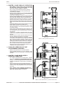
1
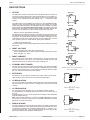
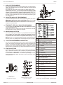
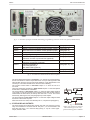
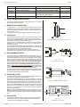
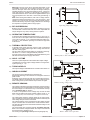
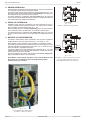
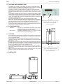
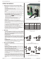
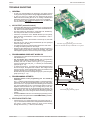
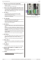
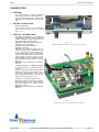
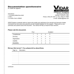
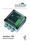
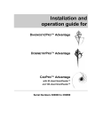
SM 800 - series
•
•
•
•
SM 7-80
SM 18-50
SM 70-AR-24
SM 400-AR-4
Schulz-Electronic GmbH | Postfach 11 01 18 . D-76487 Baden-Baden . Hausanschrift | Dr.-Rudolf-Eberle-Str. 2 . 76534 Baden-Baden
Fon +49.7223.9636.0 . Fax + 49.7223.9636.90 . [email protected] . www.schulz-electronic.de
Geschäftsführer | Dipl.-Ing. (FH) Hubert Maier HR | Baden-Baden HRB 1299 . UST-ID-Nr. 143 464 986 . Steuernr. 33015-57707
VR Bank Sinzheim eG | BLZ 665 623 00 . Kto. 30 26 00
SM800
DELTA ELEKTRONIKA BV
Safety Instructions
Caution
The following safety precautions must be observed during all phases of operation, service and
repair of this equipment. Failure to comply with the safety precautions or warnings in this document
violates safety standards of design, manufacture and intended use of this equipment and may
impair the built-in protections within.
Delta Elektronika shall not be liable for user’s failure to comply with these requirements.
Installation Category
The Delta Elektronika power supplies have been evaluated to installation category II.(Over voltage
category II)
Grounding
This product is a safety Class 1 instrument. To minimize shock hazard, the instrument chassis
must be connected to the AC Power Supply mains through a tree or four conductor power cable for
resp. a single or three phase unit, with the ground wire firmly connected to an electrical ground
(safety ground) at the power outlet.
For instruments designed to be hard-wired to supply mains, the protective earth terminal must be
connected to the safety electrical ground before another connection is made. Any interruption of
the protective ground conductor, or disconnection of the protective earth terminal will cause a
potential shock hazard that might cause personal injury.
Fuses
Fuses must be changed by authorized Delta Elektronika service personnel only, for continued
protection against risk of fire.
Input Ratings
Do not use an AC Supply which exceeds the input voltage and frequency rating of this instrument.
The input voltage and frequency rating of the Delta Elektronika power supply series are stated in
the accompanying datasheet.
Live Circuits
Operating personnel must not remove the instrument cover. No internal adjustment or component
replacement is allowed by non Delta Elektronika qualified personnel. Never replace components
with the power cable connected. To avoid injuries, always disconnect power, discharge circuits and
remove external voltage sources before touching components.
Parts Substitutions & Modifications
Parts substitutions and modifications are allowed by authorized Delta Elektronika service personnel
only. For repairs or modifications the unit must be returned to a Delta Elektronika service facility.
October 2007
SAFETY INSTRUCTIONS
Page 2 - 1
DELTA ELEKTRONIKA BV
SM800
Environmental Conditions
The Delta Elektronika power supplies safety approval applies to the following operating conditions:
Indoor use
Ambient temperature
Maximum relative humidity
: -20 to 50 °C
: 95%, non condensing, up to 40 °C
: 75%, non condensing, up to 50 °C
Altitude: up to 2000m
Pollution degree 2
Caution risk of electrical Shock
!
Instruction manual symbol. The instrument will be marked with this symbol when it is
necessary for the user to refer to the instruction manual
Protective ground conductor terminal
o
Off (supply)
I
On (Supply)
WEEE
(Waste Electrical & Electronic Equipment)
Correct Disposal of this Product
Applicable in the European Union.
This marking shown on the product, its packing or its literature indicates that
it should not be disposed with other wastes at the end of its working life, but
should be collected separately to recycle it responsibly to promote the
sustainable reuse of material resources.
Page 2 - 2
SAFETY INSTRUCTIONS
October 2007
SM800
DELTA ELEKTRONIKA BV
DESCRIPTIONS
1)
SM 7.5-80
OUTPUT
The SM7.5-80, SM18-50, SM70-AR-24 and the SM400-AR-4 can either be
used as a constant voltage source with current limiting or as a constant current source with voltage limiting. The change of mode occurs sharply at the
crossing of the voltage and current settings. fig. 3 - 1 shows the output
ranges.
The SM70-AR-24 and the SM400-AR-4 feature an AUTORANGING facility
where the power supply automatically switches over between two current
ranges. This switching, which is unnoticable for the user, results in a versatile
power supply with twice the output voltage range. This means that for the
SM70-AR-24 the maximum output power of 840W is available at both 35V
and 70V. For the SM400-AR-4 this is 800W at both 200V and 400V.
SM 18-50
° DISPLAY CV/CC SETTINGS FUNCTION
The settings of the voltage and current control (also when programmed) can
be observed on the front panel meters by pressing the Display CV/CC Settings button. This allows the current limit to be set when operating in the CV
mode without shorting the output terminals, and the voltage limit to be set
when operating in the CC mode without opening the load leads.
SM 70-AR-24
° OVERLOAD PROTECTION
The power supply is fully protected against all overload conditions, including
short circuit.
2)
INPUT VOLTAGE
The power supplies have a wide input voltage range.
° At line voltages below about 100-110 VAC the output power has to be derated, see page 1-2, "Input".
3)
SM 400-AR-4
INPUT CURRENT
The unit has active power factor correction (PFC). The input current will
therefore almost be a sine wave. This means that the RMS-value and the
harmonic distortion of the input current will be relatively low.
4)
STANDBY INPUT POWER
The unit consumes very little power when in standby. This makes it possible
to leave the input power on when the output is disabled using the "Output
On/Off" function (push button on front panel) or the Remote ShutDown input
(pin 5 on connector CON E on the rear panel).
5)
fig. 3 - 1
Output ranges. Every point in the
area can be used.
EFFICIENCY
The efficiency is very high and constant over a wide output current range.
High efficiency means low power loss and low heat generation.
6)
CV REGULATION
The CV-load regulation should be measured directly on the output terminals
because a few cm of cable can have a voltage drop of several mV (at high
current!).
7)
CC REGULATION
For accurate CC-load regulation, do not use external voltage sensing.
A voltage between S- and minus output will create an error of about 0.04 %
per volt.
A voltage between S+ and + is not critical.The CC-stability is also affected by
external voltage sensing.
Note: when the unit operates in CC-mode, the DCF-LED will be on. When
the unit is in CC-mode most of the time, it is possible to disable the LED with
dipswitch 3 on SW1 (rear panel).
8)
fig. 3 - 2
Measuring ripple voltage
WRONG !
RIPPLE & NOISE
The output ripple is very low with almost no spikes. The ripple voltage has to
be measured directly on the output terminals using a probe with very short
connections (to avoid pick up of magnetic fields) (see fig. 3 - 2 and fig. 3 - 3).
At low temperatures like −20°C the ripple increases. By using high quality
electrolytic capacitors the increase is relatively low.
October 2007
DESCRIPTIONS
fig. 3 - 3
Measuring ripple voltage
RIGHT !
Page 3 - 1
DELTA ELEKTRONIKA BV
9)
SM800
ANALOG PROGRAMMING
The output voltage and current can be programmed by an external analog
voltage. This programming is very accurate and linear. The levels are all
standardised on 5V.
The inputs have a protection circuit formed by a series resistor and a
parallel zener (see fig. 3 - 4). The capacitor limits the speed to a safe
value. Note that the analog inputs (and outputs) are not floating, but the
common is connected to the negative output terminal. Wrong connection of Ø can cause earth loops which can trip the fuse. After removing
the fault, the fuse will reset (PTC-fuse). For isolated programming, see
next paragraph 10).
10)
ISOLATED ANALOG PROGRAMMING
To prevent earth loops which can cause programming errors, use an isolated programming source. If this is not possible, use the optional ISO
AMP CARD (δ-product) which can be built inside the unit.
With the ISO AMP CARD earth loops between the unit and the programming source are prevented.
11)
fig. 3 - 4
Programming inputs (internal circuit)
ETHERNET / IEEE 488 / RS232 PROGRAMMING
The Delta Elektronika PSC-ETH, PSC-488 and the PSC-232 controllers
can be built inside the unit.
Voltage and current can easily be programmed and read back. Also all
the status outputs can be read by the computer.
12)
MONITORING OUTPUTS
The monitor outputs give a voltage 0 - 5 V proportional to the output current or voltage. The output current can easily be measured using the
I-monitor (see fig. 3 - 6). The monitor outputs are buffered with op-amp’s
and protected with series resistors and parallel zeners (see fig. 3 - 7).
The table in fig. 3 - 5 shows the impedance levels of the monitoring outputs.
For using Imon on a pulsating load, see paragraph 20) of this chapter.
13)
+12V ON PROGRAMMING CONNECTOR
The +12V on the programming connector can be used to supply external
circuits. The output is current limited, but should not be overloaded. The
fuse F27_3 on pcb P647 could blow. The fuse F27_3 also protects the internal circuit, in case an external high voltage is applied by accident.
Note: this fuse is a special 600V type, always replace with the same type.
pin Description, see par.12)...17) for details
1
2
3
4
14)
STATUS OUTPUTS
All the status outputs are logic outputs. Logic "0" means the output is 0 V,
logic "1" means the output is 5 V (Ro = 500 Ohm). This makes it possible
to drive directly: an opto-coupler, a TTL gate or a CMOS gate.
The Limit Status or LIM-status is "1" in case the output voltage or current
reaches the limit setting. Which limit circuit is active can be seen on the
front panel LED’s.
5
6
7
8
9
10
11
12
13
14
15
fig. 3 - 6
External meters
using monitor outputs
Page 3 - 2
fig. 3 - 7
Buffered monitor outputs
(internal circuit)
DESCRIPTIONS
Ø, return of reference, prog. inputs and
monitor outputs (Ro = 1.2 Ohm).
current monitor output 0 - 5V
(Ro = 1.2 Ohm, Io max = 4 mA)
current programming input (0 - 5V),
Ri = 8 MOhm
CC status output, logic 1 = CC mode
(5 V / 500 Ohm)
Remote shutdown (4 - 12 V),
Ri = 5 kOhm
PSOL status output, logic 1 = PSOL
(5 V / 500 Ohm)
+12 V output
(Ro = 3 Ohm, Io max = 0.2 A)
Ø, return of status outputs, +12 V
and remote shutdown
reference voltage 5.1 V
(Ro = 1.2 Ohm, Io max = 4 mA)
voltage monitor output 0 - 5V
Ro = 1.2 Ohm, Io max = 4 mA)
voltage programming input (0 - 5V)
Ri = 8 MOhm
OT - status output, logic 1 = OT
(5 V / 500 Ohm)
LIM - status output, logic 1 = LIM
(5 V / 500 Ohm)
DCF - status output, logic 1 = DCF
(5 V / 500 Ohm)
ACF - status output, logic 1 = ACF
(5 V / 500 Ohm)
fig. 3 - 5
Connections ANALOG PROG. CONNECTOR
October 2007
SM800
DELTA ELEKTRONIKA BV
fig. 3 - 8 Location of output terminals and analog programming connector on the rear panel (standard unit)
CON A
Interlock Connector
paragraph 18)
CON B
Master Connector for Master / Slave operation (output)
paragraph 31)
CON C
Slave Connector for Master / Slave operation (input)
paragraph 31)
CON D
Relay Outputs, contacts 1 - 6
paragraph 15)
CON E
Analog Programming Connector
paragraph 9)
CON F
PSC-ETH, user inputs
PSC-232, from PC or previous PSC (optional)
paragraph 11)
CON G
PSC-ETH, user outputs
PSC-232, to next PSC (optional)
paragraph 11)
CON H
PSC-ETH (optional) or
PSC-488 (optional) or
ISO AMP CARD (optional)
paragraph 10), 11)
SW 1
Various settings
paragraph 16)
SW 2
Settings for PSC-488 and PSC-232 (optional)
-
ACF / DCF
fig. 3 - 9 Connectors and switches on the rear panel
The Over Temperature Status or OT status is "1" in case of an over temperature,
the OT LED will be on and the output shuts down. As a pre-warning the OT LED
starts to blink when the unit runs hot but the situation of over temperature is not
reached yet. The status will still be low when the LED is blinking.
The Current Control Status or CC-status output is "1" when the unit is in
CC-mode.
The Power Sink OverLoad Status or PSOL-status output is "1" when the optional
Power Sink is overloaded or overheated.
The AC-Fail Status or ACF-status output is "1" when the input voltage is below
115V (peak, not rms) for more than 10 ms. Note that if you want the ACF-status to
switch before the DCF-status, the hold-up time has to be > 10 ms. This can be
achieved by reducing the load, see paragraph 25) of this chapter.
The DC-Fail Status or DCF-status output is "1" when the output voltage is either
5% below or above the set point.
When the unit is in CC-mode, DCF will always be "1", see previous paragraph 7).
15)
STATUS RELAY OUTPUTS
The power supply has 2 status relay outputs, with each a change-over contact.
They are connected to connector CON D. The pins 1, 2, 3 are connected to the
DCF-relay and pins 4, 5, 6 to the ACF-relay (see fig. 3 - 10). Pin 1 is the upper
output, closest to SW1.
October 2007
DESCRIPTIONS
fig. 3 - 10
Status relay outputs on CON D.
This situation gives the relay
positions during fault condition.
Page 3 - 3
DELTA ELEKTRONIKA BV
SM800
Switch no. ON position
SW 1 - 1
Programming via 15pole connector CON E (analog).
SW 1 - 2
‘Output On’ after mains on
SW 1 - 3
DCF LED enabled
SW 1 - 4
16)
Parallel Master / Slave operation
OFF position
Op tional pro gram ming with e.g.
PSC-232, PSC-488, ISO AMP CARD
‘Output Off’ after mains on
DCF LED disabled (DCF status and
DCF relay are still enabled)
Series Master / Slave operation
Default Setting
ON (up)
OFF (down)
ON (up)
ON (up)
FUNCTION SWITCHES ON SW1
In the above table the functions of the dipswitches 1-4 of switch
SW1 (rear side) are explained.
17)
REMOTE SHUTDOWN (RSD)
A voltage of +4 V...+12 V on the Remote ShutDown input on the
programming connector CON E will switch off the output of the unit.
It is also possible to use a relay contact or a switch to shut the unit
down (see fig. 3 - 11).
In standby mode the power supply consumes very little power.
18)
INTERLOCK
The Interlock connector (CON A, rear panel) has 2 inputs which
have to be connected together to turn on the output of the unit.
As soon as the link between the 2 inputs of the Interlock connector
is disrupted, the output of the unit shuts down.
It can be used in combination with a cabinet door contact (safety
precaution) or as an emergency break to stop a motor which is
powered by the unit.
In case the link is disrupted the RSD LED will light. In contrast with
Remote ShutDown, also the DCF LED will be on, the DCF status
will be high and the relay contact will change.
Once the inputs are connected again, the output will be on.
No voltage may be applied to the pins in the Interlock connector.
19)
PROGRAMMING SPEED
The rise and fall time is measured with a step waveform at the CV
prog. input. Programming from a low to a high output voltage is
nearly load independent, but programming down to a low voltage
takes more time on lighter loads. This is caused by the output capacitors, which can only be discharged by the load because the
power supply cannot sink current. With the Power Sink option,
also the programming down speed is nearly load independent.
When having a unit with a Fast Programming option, the rise and
fall time is 5 to 25 times faster (see datasheet). The programming
source must be floating or otherwise an ISO AMP CARD must be
used, a non-floating source will result in slope distortion.
For a fast programming unit it is generally not recommended to use
remote sensing or serial / parallel operation. Consult factory for advice. Note that the output ripple is higher.
20)
fig. 3 - 12
Pulsating load current
PULSATING LOAD
To avoid overheating the output capacitors, the AC component of
the load current should be limited (see fig. 3 - 12).
One method of decreasing the AC current through the output capacitor is by using a large external electrolytic capacitor in parallel
with the load. Care must be taken so that the capacitor in combination with the lead inductance will not form a series resonant circuit!
When using remote sensing on a pulsating load (for instance a
DC-motor), use a capacitor in series with a resistor over the load
(see fig. 3 - 13). Like this the AC-component caused by the pulsating of the load is filtered.
Note: in case of a pulsating load, the I monitor voltage will not exactly match the output current. This is mainly caused by the current
through the output capacitors. Remote sensing will worsen this effect.
21)
fig. 3 - 11
Remote ShutDown using a relay contact
fig. 3 - 13
Remote sensing on a pulsating load
INSULATION
For safety the insulation of the separating components (transformers) between input and output is tested at 3750 Vrms during
1 minute. This is tested before assembly.
Page 3 - 4
DESCRIPTIONS
fig. 3 - 14
Insulation test voltages
October 2007
SM800
DELTA ELEKTRONIKA BV
Warning! The 3750 Vrms cannot be tested afterwards on the
assembled unit because the insulation between the components on the input side to the case (like the bridge rectifier) is
specified at 2500 Vrms. Since the insulation output - case is low
(only 600 VDC) the insulation of the primary components to
case will break down when 3750 Vrms is applied between input
and output (2500 Vrms + 600 VDC < 3750 Vrms) (see also fig. 3
- 14).
Note: when testing the insulation, take care to charge and discharge the capacitors between input - case and output - case
slowly (e.g. in one second). This to prevent high peak currents,
which could destroy the power supply. Make sure to discharge
the capacitors completely before using it again.
22)
RFI SUPPRESSION
fig. 3 - 15
Operating temperature ranges
Both the input and output have RFI filters, resulting in very low
conducted RFI to the line and load. Due to the output filter the
output voltage is very clean, having almost no spikes.
23)
OPERATING TEMPERATURE
At full power the operating temperature range is –20 to +50 °C.
From 50 to 60 °C the output current has to be derated linearly to
75 % at 60 °C (see fig. 3 - 15). These temperatures hold for normal use, i.e. the ventilation openings on the left and right side
must be free.
24)
THERMAL PROTECTION
A thermal switch shuts down the output in case of insufficient
cooling.The OT status will be high. After cooling down the unit
will start working again.
The OT-LED on the front panel will be on and the OT-status signal will be "1" in case of a tripped thermal protection.
As a pre-warning the OT-LED blinks (status will still be low), this
will start before the power supply shuts down.
25)
fig. 3 - 16
Hold-up time vs Vout with Iout as a parameter
HOLD - UP TIME
The hold - up time depends on the load and the output voltage.
A lighter load or a lower output voltage results in a longer hold up time (see fig. 3 - 16).
26)
TURN ON DELAY
The output voltage is available about 0.5 s after mains switch on.
27)
INRUSH CURRENT
The inrush current is limited with a special circuit.
Repeatedly switching on and off does not change the maximum
peak current.
Switching on and off at a fast rate can overheat the inrush current limiter. With the result that the unit does not start anymore.
After cooling down (mains switched off) it will be OK again.
28)
REMOTE SENSING
fig. 3 - 17
Remote sensing, voltage drop in load leads sub-
The voltage at the load can be kept constant by remote sensing.
This feature is not recommended for normal use but only when
the load voltage is not allowed to vary a few millivolts. Always
use a shielded cable for sensing.
In order to compensate for the voltage drop across the load
leads, the unit will have to supply a higher voltage, see fig. 3 - 17:
Uout = (voltage drop across each lead) + (voltage across the load).
The voltage limit reads the voltage directly at the output terminals. The setting for the limit must therefore be increased by the
total voltage drop across the load leads.
The voltage display on the frontpanel and the voltage monitor
output on CON E are connected to the sense leads and therefore read the voltage across the load and not the voltage on the
output terminals.
The sense leads are protected against accidental interruption. The maximum voltage between the output terminals and
the sense inputs is limited at 2.5 V.
For sensing on a pulsating load see previous paragraph 20).
October 2007
DESCRIPTIONS
fig. 3 - 18
Master / Slave series operation
Page 3 - 5
DELTA ELEKTRONIKA BV
29)
SM800
SERIES OPERATION
Series operation is allowed up to 600V total voltage. The power supplies can
be connected in series without special precautions.
For easier control, Master / Slave operation is recommended (see fig. 3 - 18).
By using the Master / Slave Series feature a dual tracking power supply can
be made with one unit as master and one as slave.
For series operation in combination with Power Sink option, all units must
have a Power Sink built inside otherwise no power can be absorbed. Refer to
Power Sink manual for details and restrictions.
30)
PARALLEL OPERATION
Paralleling of the units has no limitations. The power supplies can be connected in parallel without special precautions. For easier control, Master /
Slave operation is recommended (see fig. 3 - 19).
Normal parallel operation of Fast Programming units can give problems,
each combination has to be tested first, in combination with the load !
For parallel operation in combination with Power Sink option, only one unit
can have a Power Sink. Refer to Power Sink manual for details and restrictions.
31)
fig. 3 - 19
Master / Slave parallel operation
MASTER / SLAVE OPERATION
The Master / Slave feature makes it possible to use the power supplies as
building blocks to form one large unit (see fig. 3 - 18 and fig. 3 - 19).
Mixed parallel - series operation is also possible, to a maximum of 600V.
The resulting combination of units behaves like one power supply and can be
manually controlled or programmed on the master. Fig. 3 - 20 shows a computer controlled M / S parallel combination.
Connect the different units with standard RJ45 cables (see fig. 3 - 21), using
CON B and CON C on the rear side. With dipswitch 4 of switch SW1 the Parallel or Series mode can be selected.
The slaves will follow the master. The result is true current or voltage sharing in the parallel or series mode respectively.
Note: Master / Slave parallel operation is not recommended for more
than 4 units or in combination with Fast Programming option.
Consult factory for a solution.
fig. 3 - 20
The Master / Slave combination can also
be programmed with the interfaces
PSC-ETH, PSC-488 or the PSC-232
fig. 3 - 21
Use standard UTP cables (RJ45)
for Master / Slave operation
Page 3 - 6
DESCRIPTIONS
October 2007
SM800
32)
DELTA ELEKTRONIKA BV
VOLTAGE AND CURRENT LIMIT
The Voltage and Current Limits maintain the output to a safe preset value.
They do not trip, so no resetting is needed after a fault. It can be very handy to
have hardware limits when the power supply is programmed.
The limits can easily be set by pressing the DISPLAY LIMITS button and
adjusting the limit potentiometers with a screwdriver. The LED’s next to the
limit potmeters indicate the activity of each limit, also the LIM-status output will
be "1".
The Voltage Limit will protect your circuit from unwanted high voltages. A high
output voltage could be caused by accidental interruption of leads, accidentally
turning up the voltage potmeter, a programming error or a defect in the power
supply. The Voltage Limit circuit uses a separate voltage divider connected directly to the output terminals.
The Current Limit protects your circuit from unwanted high currents.
Note: In the Autoranging units the limit circuits are also used as "range limits".
This can be confusing. Example: an SM70-AR-24 operating in the range above
35 V will automatically reduce the limit setting to a maximum of 12 A.
Warning: if this unit operates in the range below 35V, this setting is 24 A !
Take care the output cabling and the load can withstand such a high current or
otherwise reduce the limit setting to a lower value.
33)
POTENTIOMETERS
° Standard:
° Option P001:
34)
- CV and CC potentiometers with knobs at front panel,
Voltage Limit and Current Limit potentiometers with
screwdriver adjustment at the front panel.
- Screwdriver adjustment for CV, CC, Voltage Limit and
Current Limit at the front panel (fig. 3 - 22).
COOLING
A low noise blower cools the unit. The speed of the fan depends on the temperature of the internal heatsink. Normally at 50 °C ambient and full load the fan
will not work at full speed.
A special feature is that the fan blows through a tunnel where the heatsink is
situated, the delicate control circuitry is separated and will not be in the airflow
path (see fig. 3 - 23).
Because the air enters at the rear side and exits at the left and right side, it is
possible to stack the power supplies, no distance between the units is required.
Because only one of the ventilation openings at the left side or right side should
be free, it is possible to put two units in parallel in a rack.
For long life the temperature of the air entering on the left side, should be
below 35 °C under normal conditions. Under extreme conditions it should be
below 50 °C.
Note: The control circuit makes the fan start in a pulsating mode, during which
period it can produce a high pitched sound. This is normal.
35)
fig. 3 - 22
Screwdriver adjustment at front panel.
Behind the plastic caps, the CV- and
CC-settings can be adjusted
with a screwdriver.
DIMENSIONS
October 2007
DESCRIPTIONS
fig. 3 - 23
The fan blows through an internal tunnel,
where the heatsink is situated.
Always take care to have at least one air
outlet unobstructed.
Page 3 - 7
DELTA ELEKTRONIKA BV
SM800
OPERATING MANUAL
1)
OPERATING THE UNIT FOR THE FIRST TIME
•
•
•
•
•
•
•
•
•
•
•
•
•
•
2)
Check there is no condensation on the unit. If there is, allow some
time to dry.
Check there is a link between + and S+ and between – and S– on
the SENSE BLOCK (on rear panel).
Check there is a link between the inputs of the Interlock (CON A,
rear panel).
Set the CV and CC potentiometers to minimum (fully anti clockwise).
For recommended cable diameters and torque (see table 4 - 1)
With high output current make sure to use low resistive connections between the power supply and the load:
- Mount the cable lugs directly on the tinned output strips
followed by a washer, a split washer and a nut (see fig. 4 - 1).
Always in this order!
- Never place washers between the lugs and the strips
because this can result in excessive heat!
- Only use nuts and washers supplied with the unit.
Switch on unit.
Disable the Keylock function, see next paragraph 2).
Check the unit is not in Remote CV or Remote CC (LED’s for this
function should be off). Press the REMOTE/LOCAL button until
both LED’s are off.
Turn on the output by pressing the OUTPUT ON/OFF button.
Turn both the CV and CC potentiometer a few turns clock wise.
A voltage should now be present on the output.
By pressing the DISPLAY CV/CC SETTING button, the meters
will show the setting of the CV and CC potentiometer.
By pressing the DISPLAY LIMITS button, the voltmeter will show
the setting of the CV-limit and the CC-limit potentiometer.
Check the cooling of the unit is not obstructed.
KEYLOCK
If the function KEYLOCK is activated, it is no longer possible to
operate the REMOTE/LOCAL button and the OUTPUT ON/OFF
button. This function can be useful to protect the output from accidental shut down. The function KEYLOCK does not influence the
operating of the potentiometers.
• Activate Keylock:
Pressing the buttons DISPLAY SETTINGS and DISPLAY
LIMITS at the same time for more than 3 seconds, activates the
function KEYLOCK. The moment this function is activated, the
LED’s for REMOTE CV / CC and for OUTPUT ON will blink a few
times.
• Disable Keylock:
Pressing the same buttons again for 3 seconds, disables the
Keylock function. The LED’s for REMOTE CV / CC and for OUTPUT ON will blink again to indicate the new setting.
•
3)
ANALOG PROGRAMMING
•
•
•
•
•
•
Set dipswitch 1 of SW1 in position ON to select CON E for programming.
Disable Keylock.
Set the unit in REMOTE CV for voltage programming and/or in
REMOTE CC for current programming.
Use the REMOTE/LOCAL button and push this button several
times until the right setting is activated.
Note that pushing the REMOTE/LOCAL button will shut down the
output to avoid accidental damage to the load.
Connect the programming voltage source(s) (0 - 5 V) to the analog programming connector CON E on the rear panel (see fig.
4 - 2 and fig. 4 - 3). Always use a shielded cable (max. 30 meter)
for programming.
Turn the output on again with the OUTPUT ON/OFF button.
If only the voltage is programmed, the maximum current can still
be set with the CC potentiometer and vice versa. If this is not desirable the unit can be ordered with Option P001 in order to have
a fixed setting for the CV or the CC potentiometer on the front
panel.
Page 4 - 1
fig. 4 - 1
Low resistive cable connection by mounting the
cables directly on the tinned output strips
Unit
Output cables
[mm2]
Bolts
Torque
[Nm]
SM7.5-80
16
M5
5
SM18-50
10
M5
5
SM70-AR-24
4
M5
5
SM400-AR-4
1
M5
5
table 4 - 1
Recommended cable diameters and
mounting torque
fig. 4 - 2
Programming by voltage:
left voltage -, right current programming
fig. 4 - 3
Programming by current
left voltage -, right current programming
OPERATING MAINTENANCE TROUBLE SHOOTING CALIBRATING
October 2007
SM800
DELTA ELEKTRONIKA BV
To avoid hum or noise, the programming cable may have to
be twisted in some cases.
• To program the unit by current instead of voltage, simply use a
parallel resistor as a current to voltage converter.
• Pressing the DISPLAY SETTINGS button will show the programmed values for CV and CC.
• CAUTION: The analog inputs are not isolated from the output.
The Ø of the prog. input (pin 1) is internally connected to the
S–, the S– is connected to the negative output. To protect the
internal wiring a 650 mA self-resetting fuse is connected in series (F27_1 on P647). To avoid earth loops, use an isolated
programming source. If this is not possible see next paragraph 4), for using the optional ISO AMP CARD.
•
4)
ANALOG PROGRAMMING WITH ISO AMP CARD
For programming via the ISO AMP CARD, set dipswitch 1 on
SW1 in the position OFF.
• When the ISO AMP CARD is built inside the unit, CON E has
been covered. Use CON H instead. The pinning of CON H is
equal to the pinning of CON E.
• For further operating instructions, see previous paragraph 3).
•
5)
fig. 4 - 4
Remote control
Ethernet / IEEE 488 / RS232 PROGRAMMING
Set dipswitch 1 on SW1 in position OFF for programming with
the PSC-ETH, the PSC-488 or the PSC-232.
With dipswitch 1 in this position, the signals Vprog (pin 11) and
Iprog (pin 3) are disabled on CON E. All the other signals can
still be used. For Ethernet programming CON H must be used,
CON F and G can be used for the user in- and outputs.
For IEEE488 also CON H must be used for programming.
For RS232 programming CON F and G must be used.
• Set the unit in REMOTE CV for voltage programming and/or in
REMOTE CC for current programming using the SCPI commands (see manual PSC) or using the REMOTE/LOCAL button on the unit. Push this button several times until the right
setting is activated. Setting the unit in REMOTE or LOCAL will
cause the output to shut down to avoid accidental damage to
the load. Turn it on again using the SCPI command or with the
OUTPUT ON/OFF button.
• Set dipswitch 1 on SW1 in position ON to enable CON E again
for analog programming.
In this position voltage and current programming on CON F
and H is disabled. The other functions and signals can still be
programmed and read back.
•
6)
MONITORING OUTPUTS
•
•
7)
The 5 V level is compatible with most interfaces.
The monitoring outputs can drive a meter directly, fig. 4 - 4.
STATUS OUTPUTS
•
8)
fig. 4 - 5
Local sensing
fig. 4 - 6
Remote sensing with shielded wires
The status outputs have a separate Ø connection (pin 8) to
avoid unwanted offsets in the programming. This pin is protected with a 650 mA self resetting fuse (F27_2 on P647).
REMOTE SENSING
Remove the links on the SENSE BLOCK (on rear panel) and
connect sense leads (thin shielded measuring wires) to S+
and S– (see fig. 4 - 5 and fig. 4 - 6).
• With remote sensing the voltage on the load can be kept constant. The voltage drop in the load leads will be compensated.
This feature is not recommended for normal use, because it
can easily give problems.
• Max. 2 V per load lead can be compensated. Note that the
voltage drop in the leads decreases the max. output voltage
rating. In fig. 4 - 7 it can be seen that on a 15V power supply
only 11V will be available on the load when 2x 2V compensation is used.
• In order to prevent interference, it is advisable to twist the
sense leads. To minimise the inductance in the load leads
keep the leads close to each other. The inductance of the
loads leads could give a problem with pulsating loads. In this
•
October 2007
fig. 4 - 7
Remote sensing, voltage drop in load leads
subtracts from max. output
OPERATING MAINTENANCE TROUBLE SHOOTING CALIBRATING
Page 4 - 2
DELTA ELEKTRONIKA BV
SM800
case a large electrolytic capacitor (Cd) in series with a
damping resistor (Rd) both in parallel with the load will help
(see fig. 4 - 6). Check that the capacitor Cd in combination
with the load leads and resistor Rd forms a well damped circuit.
• Since the voltmeter is internally connected to the sensing
terminals, it will automatically indicate the voltage on the
load. Note that the voltage measured on the load will be
lower than on the output terminals.
• The Over Voltage Limit measures the voltage on the output
terminals, so the OVL setting should be increased by the
total voltage drop in the load leads.
9)
BATTERY CHARGER
Suggested Circuit Breakers for protection power supply
Model
Type number Brand
Circuit Breaker
Remarks
SM7.5-80
S281 UC-B 100 ABB
-
SM18-50
S281 UC-Z 63 ABB
-
SM70-AR-24 S281 UC-Z 25 ABB
-
SM400-AR-4 S281 UC-Z 6
extra parallel diode
on output needed.
2x BYT261in series
ABB
table 4 - 2
Circuit breakers for protection.
The CV / CC regulated power supplies are ideal battery
chargers. Once the output is set at the correct voltage the
battery will charge constantly without overcharging.
This can be useful for emergency power systems.
• Protective measures
Use a CIRCUIT-BREAKER in series in order to protect the
power supply from accidental reverse connection (see
fig. 4 - 8). The circuit-breaker should have a DC voltage rating twice the battery voltage. Use the very fast type (Z), a
type meant for protecting semiconductors (see table 4 - 2).
The unit has a reverse diode in parallel with the output, this
diode and the wiring cannot withstand the thousands of
amperes supplied by a wrongly connected battery.
•
10)
REMOTE SHUTDOWN
The Remote Shutdown can be operated on CON E by a
voltage of +4V...+12V or by a relay contact between Vref
and Remote ShutDown (pin 9 and 5) (see fig. 4 - 9).
• When the unit is programmed with an optional PSC, a
software command can be used for Remote Shutdown.
• In the Remote Shutdown condition, the RSD LED will light.
The DCF LED, DCF status and the DCF relay will be off.
•
fig. 4 - 8
Charging battery with a circuit-breaker in series
Important: If the link from the Interlock connector (CON A)
has been removed, the RSD LED will be on, but in this
condition also the DCF LED, the DCF status and the DCF
relay will be on.
11)
MASTER / SLAVE SERIES OPERATION
•
•
•
•
•
Connect output terminals and test system in normal
series operation. Ensure that all (output) power connections are reliable.
The voltage drop in the connecting leads between the units
should be kept < 10 mV.
Switch off all units. Connect units as shown in fig. 4 - 10.
To connect the slaves with the master via CON B and CON
C, use standard UTP cables (RJ45).
On all units put dipswitch 4 of SW1 in position OFF to set
the units in M/S series mode.
After turning the units on again, the slaves will be in Remote
CV mode and the Keylock, see previous paragraph 2) is activated. This is because the unit automatically detects the
presence of the RJ45 connector in CON C (if this cable is
connected to another unit).
If the RJ45 connector is removed from CON C when the
unit is turned on, the output will shut down to avoid
accidental damage.
If the cable is inserted when the unit is turned on, the output
shuts down, the unit changes to Remote CV / CC, the
Keylock will be activated and the output will turn back on.
If dipswitch 4 of SW1 is operated when the unit is turned on,
the output will shutdown to avoid accidental damage.
The max. number of slaves is only limited by the max. total
voltage of 600 V.
fig. 4 - 9
Remote shutdown with switch
fig. 4 - 10
Master / Slave series connection
Page 4 - 3
OPERATING MAINTENANCE TROUBLE SHOOTING CALIBRATING
October 2007
SM800
12)
MASTER / SLAVE PARALLEL OPERATION
•
•
•
•
•
•
13)
Note: Master / Slave parallel is not recommended
for more than 4 units, consult factory for using
more than 4 power supplies in parallel.
First, connect output terminals and test system in
normal parallel operation. Ensure that all power
connections are reliable.
Second, switch off all units. To connect the slaves with
the master via CON B and CON C, use standard RJ45
connectors according to fig. 4 - 11.
On all units put dipswitch 4 of SW1 in position ON to set
the units in M/S parallel mode. In this mode the DCF
LED, DCF relay and DCF status on the slaves are
disabled because the slaves are always in CC mode.
After turning the units on again, the slaves will be in
Remote CC mode and the Keylock, see previous paragraph 2) is activated. This is because the unit automatically
detects the presence of the RJ45 connector in CON C
(if this cable is connected to another unit).
If the RJ45 connector is removed from CON C when
the unit is turned on, the output will shutdown to avoid
accidental damage.
If the cable is inserted when the unit is turned on, the
output shuts down, the unit changes to Remote CV /
CC, the Keylock will be activated and the output will
turn back on.
If dipswitch 4 of SW1 is operated when the unit is
turned on, the output will shutdown to avoid accidental
damage.
Stack the units to create a minimum distance between
the units. Keep the load close to the master.
Use copper strips (preferred) or short thick cables to
connect the units. Make sure the strips are mounted
with a minimum length to keep the voltage drop between a unit and the bus bar below 10 mV. Also keep
the strips close to each other to have a low inductance.
Not following these instructions can cause instability.
The S- and S+ could be connected to the load if
desired, but this is not recommended because of the
complexity and possible instability.
fig. 4 - 11
Master / Slave parallel connections
PARALLEL OPERATION OF FAST
PROGRAMMING VERSIONS:
•
•
14)
DELTA ELEKTRONIKA BV
Master / Slave operation is not recommended.
Normal parallel operation can give problems, each
combination has to be tested first in combination with
the load.
MASTER / SLAVE MIXED SERIES /
PARALLEL OPERATION
For complex combinations as mixed series - parallel,
always use a MASTER / SLAVE SERIES ADAPTER.
• See fig. 4 - 12 for an example of how to connect 2 units
in series in parallel with 2 units in series, controlled by 1
master.
• Set the programming mode with the knob Remote / Local on the front panel. The serial slaves must be in Remote CV mode. The parallel slave must be in Remote
CC mode.
• Note: A Master / Slave combination can always be
programmed, also with the IEEE488 / RS232 controller
(PSC-448 / PSC-232 (both δ-products)).
•
fig. 4 - 12
Master / Slave mixed series - parallel connections
October 2007
OPERATING MAINTENANCE TROUBLE SHOOTING CALIBRATING
Page 4 - 4
DELTA ELEKTRONIKA BV
SM800
OPERATING AND STORAGE CONDITIONS
1)
TEMPERATURE
The operating temperature range at full load is –20 to +50 °C.
But this temperature range only holds when the AIR-INTAKE and
at least one of the AIR-OUTLETS is unobstructed and the temperature of the AIR-INTAKE is not higher than +50 °C.
• Please note: a lower temperature extends the life of the
power supply.
• When the power supply is mounted in a cabinet please note that
the temperature of the AIR-INTAKE should be kept low and avoid
a short circuit in the airflow i.e. the hot air leaving the AIR-OUTLET
entering the AIR-INTAKE again.
• The storage temperature range is –40 to +85 °C.
•
2)
HUMIDITY
During normal operation humidity will not harm the power supply,
provided the air is not aggressive. The heat normally produced in
the power supply will keep it dry.
• Condensation.
Avoid condensation inside the power supply, break-down could
be the result.
Condensation can occur during a period the power supply is
switched off (or operating at no load) and the ambient temperature
is increasing .
Always allow the power supply to dry before switching it on again.
•
3)
fig. 4 - 13
The fan blows through an internal tunnel,
where the heatsink is situated.
Always take care to have at least one air outlet
unobstructed.
GALVANIC INDUSTRY
For using the power supplies in the galvanic industry it is strongly
recommended to take precautions against an aggressive environment.
• An aggressive environment with acid, salt, etc. can harm the electronic components. Sometimes even the copper tracks on the
printed circuit boards dissolve.
• To avoid problems, the power supplies should be mounted in a
relatively clean room, or mounted in a cabinet receiving clean air
with over pressure, or in a cabinet with a heat exchanger.
•
MAINTENANCE
1)
GENERAL
•
2)
The SM-series power supplies normally need no maintenance or
calibration. Only care must be taken that the cooling of the unit is
not obstructed.
COOLING FAN
The built up of dust on the impeller of the fan and the heat sink fins
depends on the environment. Since the fan has over-capacity,
dust will not present a problem very quickly.
• The internal construction of the power supply is such that no dust
will reach the sensitive control circuitry, only the heat sink in a tunnel will be cooled by forced air (see fig. 4 - 13).
• The thermal protection will shut down the output in case of overheating, so the power supply will not be damaged.
• It is advisable to inspect the fan and the heat sink regularly.
•
Page 4 - 5
OPERATING MAINTENANCE TROUBLE SHOOTING CALIBRATING
October 2007
SM800
DELTA ELEKTRONIKA BV
TROUBLE SHOOTING
1)
GENERAL
In case you need assistance for repairing a unit, please contact
our engineers using the address "[email protected]".
• In case you want us to repair the unit, please first fill out the
RMA-form before sending the unit to us. Adding a detailed fault
description will help us to repair the unit as soon as possible.
On our website www.DeltaPowerSupplies.com the RMA-form
can be found under 'Support'.
•
2)
NO OUTPUT (manual control)
•
•
•
•
•
•
•
3)
Check the LEDs ‘Remote CV’ and ‘Remote CC’ on the front panel,
they should be off. Disable Keylock and press the REMOTE/LOCAL button to turn both LEDs off.
The LED ‘Output On’ should be on. If this LED is off, disable Keylock and push the button ‘OUTPUT ON/OFF’.
Check the connections on the SENSE BLOCK (at rear panel),
there should be a link between + and S+ and between – and S–
(see fig. 4 - 16).
Check if there is a link in the Interlock connector (if not, the RSD
LED will be on).
Set both the CV- and CC-limit potentiometer (at front panel) at
maximum (fully clock wise).
Turn both the CV and CC potentiometers a few turns clock-wise.
A voltage should be present on the output.
Disconnect the cables from the output and check if now there's a
voltage present on the output. If this is the situation, use a load
with a higher impedance or use a second power supply in parallel.
fig. 4 - 14
Location of programming fuses on P647
P647 is situated directly behind the rear panel
PROGRAMMING DOES NOT WORK OK
Check the unit is in Remote mode (Remote CV and/or Remote CC
LED should be on).
• The unit works OK in manual control, but in programming
mode the output voltage / current has a large error.
Probably the fuse in series with Ø (pin 1) of programming
connector tripped, the fuse (F27_1 = 650 mA) is a self-resetting
type (see fig. 4 - 14).
• To check the fuse (F27_1) measure the voltage between Ø and
the minus output, during the fault condition. The voltage should
only be a few mV, a high voltage means that an unwanted current
is flowing through pin 1 of the prog. connector.
Please check why current is flowing through pin 1 (see next paragraph 4) and fig. 4 - 15).
•
4)
PROGRAMMING OFFSETS
Unwanted offsets in the programming can be caused by
earth loops.
Fig. 4 - 15 shows a typical earthing problem. In case the load has a
connection to earth and the programming source as well, problems could occur. Improper choice of the earthing point of the load
can give a voltage drop of ∆V1. Connecting the minus or zero to a
separate earth connection can give a voltage drop of ∆V2. Because the internal wires of the programming input are thin, the
voltage drops ∆V1 and ∆V2 will be across the internal wiring as
well. Resulting in an error voltage in series with the programming
voltage.
• The best solution for this is to use a floating programming source,
a floating load or the optional internal ISO AMP CARD (δ-product).
•
5)
fig. 4 - 15
Unwanted programming offsets
STATUS OUTPUTS FAIL
•
Check fuse F27_2 in series with Ø (pin 8 of CON E) (see fig. 4 14). To check the fuse measure the voltage between Ø and the minus output, a high voltage means too much current flowing
through the fuse. F27_2 = 650 mA, self resetting.
October 2007
OPERATING MAINTENANCE TROUBLE SHOOTING CALIBRATING
Page 4 - 6
DELTA ELEKTRONIKA BV
6)
SM800
MASTER / SLAVE PARALLEL PROBLEMS
Check the voltage drop of the wiring between the master and the
slaves is < 10 mV.
• Check the wiring has a low inductance.
•
7)
OUTPUT VOLTAGE IS HIGHER THAN SET VALUE
•
8)
Check connections on SENSE BLOCK (on rear panel), For normal operation there should be a link between + and S+ and between – and S– (see also fig. 4 - 16). When remote sensing is
used, check the wires of the sensing.
OT LED on
The temperature of the internal heat sink is too high,
the output has been shut down to avoid overheating.
• Check if the cooling fan is running.
• Check if the air temperature of the air inlet (left) is below 50 °C and
the airflow is not obstructed.
•
9)
fig. 4 - 16
For normal operation links should be connected
between S+ and + and between S– and –
OT LED blinks
The temperature of the internal heat sink is getting too high, a further increase will shut down the power supply.
• Check if the cooling fan is running properly.
• Check if the air temperature of the air inlets (left) is below 50 °C
and the airflow is not obstructed.
•
10)
ACF LED on
The input voltage is too low or was intermittent because of a bad
connection. Disconnect the mains, wait a few minutes and try
again.
As soon as the ACF LED Iights, the settings for Remote CV,
Remote CC and Keylock will be saved. If the unit turns back on, it
will have the same settings. For the setting of Output On/Off after
turning the unit back on, the position of dipswitch 2 on SW1 is determining.
If the ACF situation lasts a few seconds, the output will shut down.
The ACF problem has to be solved first, before the output can be
turned on again.
• Internal error, send unit for repair. See previous paragraph 1) .
•
11)
DCF LED on
The output voltage is below the set voltage. This automatically
happens when the unit is in CC-mode (CC LED is on).
Also with an interrupted Interlock connector, the DCF LED will be
on.
• Internal error, send unit for repair. See previous paragraph 1).
•
12)
PSOL LED on
•
13)
NO LEDS on
•
•
14)
Check input.
Do not try to repair, but send for repair. See previous paragraph 1).
Blinking LEDs REMOTE CV, REMOTE CC and
OUTPUT ON
•
15)
The Power Sink is in overload or the temperature of the Power
Sink is too high. See datasheet of the Power Sink option for further
details.
This indicates the Keylock function is activated, see previous
paragraph 2) in "operating manual".
OTHER
•
If the problem persists, please fill out the RMA-form on our website
www.DeltaPowerSupplies.com. See previous paragraph 1).
Page 4 - 7
OPERATING MAINTENANCE TROUBLE SHOOTING CALIBRATING
October 2007
SM800
DELTA ELEKTRONIKA BV
CALIBRATION
1)
GENERAL
•
2)
METER CALIBRATION
•
3)
The power supplies are factory calibrated
and normally need no further calibration.
Only in special situations (for example after
repairing a unit) calibration can be necessary.
DIGITAL METERS
The full scale indication can be calibrated
with R25_31 and R25_36 on P673
(fig. 4 - 17).
SPECIAL CALIBRATIONS
The following calibrations must be done by
qualified personnel only. Wrong calibration
causes malfunction. These calibrations are
only needed after special repairs.
Warning ! Damage caused by a wrong
calibration is not warranted.
• CALIBRATING THE CURRENT
MONITOR OFFSET.
With R26_73 on P650 the offset of the CC
monitor voltage can be calibrated (see fig.
4 - 18). The unit has to be unloaded, the
output voltage has to be turned off using
the OUTPUT ON/OFF button. Measure the
offset voltage of the CC monitor on the
programming connector. Calibrate the offset on a negative value between –1 mV and
zero mV.
Warning! wrong calibration can damage
the unit.
• CALIBRATING MAX. CURRENT RANGE
or CALIBRATING CC MONITOR FULL
SCALE.
Short the output using a low resistive cable.
Measure the output current with an accurate shunt. The maximum output current
can be calibrated with R26_41. R26_41 is
located on P650 (see fig. 4 - 18).
•
fig. 4 - 17
Meter calibration with 25-turn potmeters on P673
offset
full scale
Program CC input with exactly 5.00 V.
Set output voltage to a high value, ensuring
the power supply is in CC mode. Calibrate
the current with R26_41 exactly on the
rated max. current.
Warning! Wrong calibration can damage
the unit.
fig. 4 - 18
Calibrating max. current and offset on P650
October 2007
OPERATING MAINTENANCE TROUBLE SHOOTING CALIBRATING
Page 4 - 8
P.O. BOX 27
4300 AA ZIERIKZEE
NETHERLANDS
TEL. +31 111 413656
FAX. +31 111 416919
www.DeltaPowerSupplies.com
EC Declaration of Conformity
We
Delta Elektronika
P.O. BOX 27
4300 AA Zierikzee
The Netherlands
declare under sole responsibility that the following Power Supplies:
SM 7.5-80
SM 18-50
SM 70-AR-24
SM 400-AR-4
meet the intent of Directives 2004/108/EC; 92/31/EEC; 93/68/EEC for Electromagnetic
Compatibility and
Directives 73/23/EEC; 93/68/EEC regarding Electrical Safety. (Low Voltage Directive)
Compliance was demonstrated to the following specification as listed in the official Journal
of the European Communities:
EN 61204-3 EMC, low voltage power supplies
EN 61000-6-3 Generic Emissions: (residential, light industrial)
EN 55022 Radiated and conducted, Class B
EN 61000-3-2 Power Harmonics
EN 61000-3-3 Voltage fluctuation and flicker
EN 61000-6-2 Generic Immunity: (industrial environment)
EN 61000-4-2 Electrostatic Discharge
EN 61000-4-3 Radiated electromagnetic fields
EN 61000-4-4 Electrical Fast Transients / Bursts
EN 61000-4-5 Surge on DC output
EN 61000-4-5 Surge on line input
EN 61000-4-6 RF common mode, conducted
EN 61000-4-11 Voltage variations and dips
EN 60950 Safety of IT equipment
EN 61010 Safety of electrical equipment for measurement, control and laboratory use
Managing director