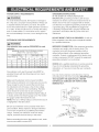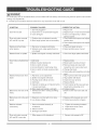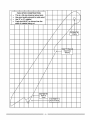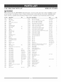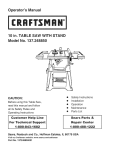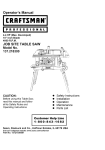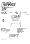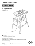
1
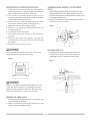
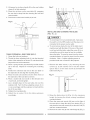
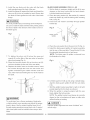
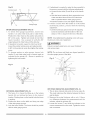
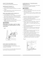
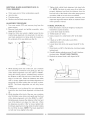
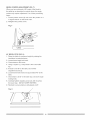
Operator's
Manuam
m
CAUTION:
Before using this Table Saw,
read this manual and follow
all its Safety Rules and
Operating Instructions
o
o
Safety Instructions
Installation
o
+
o
Operation
Maintenance
Parts List
Customer
Help Line
1 o800o843ol 682
Sears, Roebuck
Visit
our Oraftsman
and Co., Hoffman
website:
Part No. 137218010001
Estates,
www.sears.com/craftsman
IL 60179 USA
SECTION
PAGE
Warranty ........................................................
Product Specifications ....................................
Power Tool Safety ...........................................
Tabe! Saw Safety ............................................
Electrical Reuirements and Safety ..................
Carton Content ................................................
Know Your Table Saw ......................................
2
2
3
4
5
6
8
SECTION
PAGE
Assembly and Adjustments .............................
Operation ........................................................
Maintenance ....................................................
9
17
21
Troubleshooting Guide ....................................
Push Stick Pattern ...........................................
Parts List .........................................................
22
23
24
ONE YEAR FULL WARRANTY
If this product fails due to a defect in material or workmanship within one year from the date of purchase, Sears
wil! repair it free of charge. Contact a Sears Service Center for repair.
If this product is used for commercial or rental purposes, this warranty applies only for 90 days from the date of
purchase. This warranty gives you specific legal rights, and you may also have other rights which vary from state
to state.
Sears, Roebuck & Co., Dept. 817 WA, Hoffman Estates, IL 60179
WARNING
n
Some dust crested by power sanding, sawing, grinding, drilling and other construction
chemicals
known to cause cancer, birth defects or other reproductive
harm. Some
chemicals are:
activities
examples
contains
of these
Lead from lead-based paints
Crystalline silica from bricks, cement and other masonry products
Arsenic and chromium from chemically treated lumber
Your risk from these exposures varies, depending on how often you do this type of work. To reduce your
exposure to these chemicals, work in s well ventilated ares and work with approved safety equipment such as
dust masks that are specially designed to filter out microscopic
particles.
MOTOR
SAW
HP (Maximum developed) .........................
2.5
Table Extension ............................
Right Side =8 in. Steel
Type ..........................................................
Amps .........................................................
Voltage ......................................................
Hz ..............................................................
Universal
13
120
60
Rip Capacity with Extension .........
Blade Size ....................................
17-1/2 in.
10 in.
RPM (no load) ...........................................
Thermal Overload Protection ....................
5000
YES
Rip Fence .....................................
Miter Gauge .................................
Maximum Cut Depth @ 900 ..........
Maximum Cut Depth @ 450 ..........
Maximum Diameter Dado .............
Maximum Dado Cut Width ............
YES
YES
3 in.
2=1/2 in.
6 in.
1/2 in.
l,&WARNmNG
I
To avoid electrical hazards, fire hazards or dsmsge to the table saw, use proper circuit
This table saw is wired st the factory for 110-120 Volt operation, tt must be connected
15 Ampere time delay fuse or circuit breaker. To avoid shock or fire, replace power
worn, cut or damaged in any way.
Before using your table saw, it is critical that you read and understand these safety
these rules could result in serious injury to you or damage to the table saw.
protection.
to s 110-120 Volt /
cord immediately if it is
rules.
Failure to follow
IAWARNING
U
Before using your table saw, it is critical that you read and understand
these rules could result in serious injury or damage to the table saw.
Good safety practices are a combination of common
sense, staying alert and understanding how to use your
power tool To avoid mistakes that could cause serious
injury, do not plug in your power tool until you have read
and understood the fo!!owing safety rules:
1. READ and become familiar with the entire Operator's
Manual. LEARN the tool's application, limitations and
possible hazards.
]
2. IA WARNING JLook for this symbol that identifies
important safety precautions.
It means CAUTION!
Become alert, your safety is involved if you do not
follow the safety instructions.
H
3. 1'_
DANGER
4. NEVER OPERATE THIS MACHINE WITHOUT THE
SAFETY GUARD tN PLACE FOR ALL THROUGH°
SAWING OPERATIONS.
5.
DO NOT USE tN A DANGEROUS ENVIRONMENTS
such as damp or wet locations or exposure to rain.
Keep work area well lighted.
6.
DO NOT use power tools in the presence of
flammable liquids or gases.
7.
KEEP WORK AREA CLEAN. Cluttered areas and
benches invite accidents.
KEEP CHILDREN AWAY. All visitors should be kept
at a safe distance from the work area.
9. DO NOT FORCE THE TOOL. It will do the job better
and safer at the rate for which it was designed.
10 USE THE RIGHT TOOL. Don't force the tool or
attachment to do a job for which it is not designed.
11.
Failure to follow
l& REMOVE ADJUSTING KEYS AND WRENCHES.
Form the habit of checking to see that keys and
adjusting wrenches are removed from the tool before
turning ON.
17. NEVER LEAVE TOOL RUNNING UNATTENDED.
TURN THE POWER "OFF". Do not leave the tool
before it comes to a complete stop.
l& NEVER STAND ON TOOL. Serious injury could
occur if the too! is tipped or if the cutting tool is
unintentionally contacted.
19. DO NOT OVERREACH.
balance at all times.
Keep proper footing and
ILook for this symbol that identifies
important safety precautions.
It means CAUTION!
Become alert, your safety is involved if you do not
follow the safety instructions.
8.
these safety rules.
WEAR PROPER APPAREL. DO NOT wear loose
clothing, gloves, neckties, rings, bracelets or other
jewelry that may get caught in moving parts. Nonslip footwear is recommended. Wear protective hair
covering to contain long hair.
20_ MAINTAIN TOOLS WITH CARE. Keep tools sharp
and clean for most efficient and safest performance.
Follow instructions for lubricating and changing
accessories.
21. CHECK FOR DAMAGED OR LOOSE PARTS.
Before further use of the tool, a guard or other
part that is damaged should be carefully checked
to ensure it will operate properly and perform its
intended function. Check for alignment of moving
parts, binding of moving parts, loose mounting
and any other conditions that may affect its safe
operation. A guard or other part that is loose or
damaged should be properly adjusted repaired or
replaced.
22. MAKE WORKSHOP CHILD PROOF with padlocks,
master switches or by removing starter keys.
2& DO NOT operate the tool if you are under the
influence of any drugs, alcohol or medication that
could impair your ability to use the tool safely.
24. USE A DUST COLLECTION SYSTEM wherever
possible. Dust generated from certain materials can
be hazardous to your health and in some cases, a
fire hazard. Always operate the power tool in a wellventilated area with adequate dust removal
l& DISCONNECT TOOLS before servicing and when
changing accessories such as blades, cutters, etc.
25_ ALWAYS WEAR EYE PROTECTION. Any power
tool can throw foreign objects into your eyes which
could cause permanent eye damage. ALWAYS
wear safety goggles (not glasses) that comply with
ANSI safety standard Z87.1. Everyday glasses
have only impact resistant lenses. They ARE NOT
safety glasses. NOTE: Glasses or goggles not in
compliance with ANSI Z87.1 could cause serious
injury when they break.
14. REDUCE THE RISK OF UNINTENTIONAL
STARTING. Make sure the switch is in the OFF
position before plugging into the power supply.
26. DIRECTION OF FEED. Feed work into a blade or
cutter against the direction of rotation of the blade or
cutter only.
15. USE ONLY RECOMMENDED ACCESSORIES.
Consult the Operator's Manual for recommended
accessories. The use of improper accessories may
cause injury to you or damage to the tool
27_ DO NOT AUTHORZE ADDITIONAL USERS to
operate this power tool without the accompanying
operators manual for which the user must read &
understand.
12. WEAR A FACE MASK OR DUST MASK. Sawing,
cutting and sanding operations produce dusL
ALWAYSUSESAWBLADEGUARD,splitterand
anti-kickback
pawlsforeveryoperation
forwhich
theycanbeused,includingthrough-sawing.
Through-sawing
operations
arethoseinwhichthe
bladecutscompletely
throughtheworkpiece
when
rippingorcross-cutting.
2. ALWAYSHOLDWORKFIRMLYagainstthemiter
gaugeor ripfence.
3_
4_
USE A PUSH STICK when required. Always use a
push stick when ripping narrow stock. Refer to
ripping instructions in this Operator's Manual where
the push stick is covered in detail. A pattern for
making your own push stick is included on page 23_
NEVER PERFORM ANY OPERATION "FREE
HAND", which means using only your hands to
support or guide the workpiece. Always use either
the fence or the miter gauge to position and guide
the work.
IA DA"GER
l
FREEHAND CUTTING JS THE MAJOR CAUSE OF
KICK-BACK & FINGER/HAND AMPUTATIONS.
5.
NEVER STAND or have any part of your body in
line with the path of the saw blade. Keep your
hands out of the saw blade path.
6.
NEVER REACH behind or over the cutting tool for
any reason.
7.
NEVER use a rip fence when cross cutting.
8.
DO NOT USE a molding head with this saw.
9.
FEED WORK INTO THE BLADE against the
direction of rotation only.
10. NEVER use the rip fence as a cut-off gauge when
cross-cutting.
11. NEVER ATTEMPT TO FREE A STALLED SAW
BLADE without first turning the saw OFF. Turn
power switch OFF and disconnect the plug from the
power source immediately to prevent motor
damage & before removing material
12. PROVIDE ADEQUATE SUPPORT to the rear and
the sides of the saw table for long or wide
workpieces.
l& AVOID KICKBACKS (work thrown back towards
you) by keeping the blade sharp, the rip fence
parallel to the saw blade and by keeping the splitter,
anti-kickback pawls and guards in place and
functioning. Do not release work before it has
passed al! the way past the saw blade and is off the
table. Do not rip work that is twisted, warped or
does not have a straight edge to guide it along the
fence.
14. AVOID AWKWARD OPERATIONS and hand
positions where a sudden slip could cause your
hand to move into the saw blade.
15_ NEVER USE SOLVENTS to clean plastic parts.
Solvents could possibly dissolve or otherwise
damage the material Only a soft damp cloth
should be used to clean plastic parts.
16. MOUNT your table saw on a bench or stand before
performing any cutting operations. Refer to
ASSEMBLY AND ADJUSTMENTS on page 9_
17. NEVER CUT METALS or materials which may
make hazardous dusL
18_ ALWAYS USE tN WELL°VENTILATED AREA.
Remove sawdust frequently. Clean out sawdust
from the interior of the saw to prevent a potential
fire hazard. Attach a vacuum to the dust port for
additional sawdust removal
19_ NEVER LEAVE THE SAW running unattended. Do
not leave the saw until it comes to a complete sto G
20_ FOR proper operation follow the instructions in this
Operator's Manual. Failure to provide sawdust fag
through and removal hole wilt allow sawdust to
build up in the motor area resulting in a fire hazard
and potentia! motor damage (see page 10 for
details).
21_ DO NOT AUTHORIZE ADDITIONAL USERS to
operate this power too! without the accompanying
operators manual for which the user must read and
understan&
22_ THE REAR OF THE TABLE INSERT MUST BE
FLUSH TO THE TABLE during all sawing
operations. A rubber adjusting spacer is provided
under the rear of the insert for this purpose.
23_ DO NOT USE A DADO BLADE LARGER THAN
6 inches in diameter and Y2 inch in width. Only
use a stackable dado blade. Do not use adjustable
or wobble dadoes.
24_ NEVER PERFORM A CUTTING OPERATION
USING BOTH the rip fence and the miter gauge at
the same time. This may cause kickback and
serious injury to the operator.
POWERSUPPLYREQUIREMENTS
GROUNDING INSTRUCT_ONS
IN THE EVENT OF A MALFUNCTION
IAWARNING
n
To avoid electrica! hazards, fire hazards or damage to
the chop saw, use proper circuit protection. Always use
a separate electrical circuit for your tools. This power
too! is wired at the factory for 120V operation. Connect it
to a 120V, 15 Amp circuit and use a 15 Amp time delay
fuse or circuit breaker. To avoid shock or fire, replace
the cord immediately if it is worn, cut or damaged in any
OR
BREAKDOWN, grounding provides a path of least
resistance for electric current and reduces the risk of
electric shock. This saw is equipped with an electric
cord that has an equipment grounding conductor and
a grounding plug_ The plug MUST be plugged into
a matching receptacle that is properly installed and
grounded in accordance with ALL local codes and
ordinances.
way.
DO NOT MODIFY THE PLUG PROVIDED. If it wil! not
EXTENSION CORD REQUIREMENTS
fit the receptacle, have the proper receptacle installed
by a qualified electrician.
IAWARNING
n
Any extension cord must be GROUNDED for safe
operation.
MINIMUM GAUGE FOR EXTENSION CORDS
(AWG TYPE / 120 VOLT ONLY)
Ampere Rating
More Than
Not
More Than
0
6
10
6
10
12
Totai length in feet
25'
50'
100'
150'
18
18
16
16
16
16
16
14
14
14
12
12
_MPROPER CONNECTION of the equipment grounding
conductor can result in risk of electric shock. The
conductor (wire) with the green insulation (with or
without yellow stripes) is the equipment grounding
conductor. If repair or replacement of the electric cord
or plug is necessary, DO NOT connect the equipment
grounding conductor to a live terminal
CHECK with a qualified electrician or service personnel
if you do not completely understand the grounding
iiiiiiiiiiiiiiiiiiiiiiiiiiiiiiiiiiiiiiiiiiiiiiiiiiiiii_i_i_:_i_i_i_i_i_i_i_i_i_i_i_i_i_i_i_i_i_i_i_i_i_i_i_i_!_:JiH!i_i_i_i_i_i_i_i_i_i_i_i_i_i_i_i_i_i_i_i_i_i_i_i_i_i_i_
¸!i_i_ii_ii_ii_ii_ii_ii_ii_ii_ii_ii_!i!ii
¸i_i_i_i_i_i_i_i_i_i_i_i_i_i_i_;!_i_i_i_i_i_i_i_i_i_L_!_i_!_!i_!i!iii_i_i_i_!i_
instructions, or if you are not sure the saw is properly
grounded.
Any extension cord used for power tools MUST be
grounded (3=wire with two fiat prongs and one round
Use only 3-wire extension cords that have 3-prong
ground prong)_
grounding plugs and 3-pole grounding RECEPTACLES
THAT ACCEPT THE SAW'S PLUG. REPAIR
Make sure the extension cord is in good condition.
OR REPLACE DAMAGED OR WORN CORDS
When using an extension cord, make sure you use one
_MMED_ATELY.
heavy enough to carry the current the tool will draw.
An undersized cord will cause a drop in line voltage
3-Prong Plug
resulting in loss of power and overheating. The table
above shows the correct size to use according to
extension cord length and nameplate ampere rating. If
in doubt, use the next heavier gauge cord. The smaller
the gauge number the heavier the cord.
NOTE: The 12 to 16 Amp rating is correct for this tool It
is highlighted in the table above.
Be sure your extension cord is properly wired and in
good condition. Always replace a damaged extension
cord or have it repaired by a qualified person before
using it. Protect your extension cords from sharp
objects, excessive heat and damp or wet areas.
Grounding Lug
Make Sure This
is Connected to a
Known Ground
2-Prong
Receptacle
Adapter
Before connecting the saw to the extension cord, make
sure the saw switch is turned OFR
RECOMMENDED
Separate all parts from packing materials. Check each
part with the illustration on the next page and the "Table
of Loose Parts" to make certain all items are accounted
ACCESSORIES
IAWARN NG
n
Visit your Sears Hardware Department or see the
Craftsman Power and Hand Tools Catalog to purchase
recommended accessories for this power tool.
IAWARNING
n
To avoid the risk of personal injury:
o Do not use adjustable (wobble) type dadoes or
for, before discarding any packing material
[A WARNING
]
If any part is missing or damaged, do not attempt to
assemble the table saw, plug in the power cord, or turn
the switch ON until the missing or damaged part is
obtained and is installed correctly.
carbide tipped dado blades.
TABLE
o Use only stackable dado blades.
o Maximum dado width is 1/2 in.
® Do not use a dado with a diameter larger than 6 in.
o Do not use molding head set with this saw.
o Do not modify this power too! or use accessories not
recommended by Sears.
TOOLS
Adjustabie wrench
#2 Phittips screwdriver
Combination
screwdriver
PARTS
ITEM
DESCRIPTION
A.
B_
Table saw assembly
Blade
1
1
C.
Blade wrenches
2
D.
E.
Miter gauge
4mm Hex key
1
1
F_
Guard mounting bolt, flat washer,
Toothed washer, oval washer,
1
NEEDED
Medium screwdriver
OF LOOSE
G.
I.
J.
K.
QUANTITY
Spring washer
Blade guard and splitter
Rip fence, lock handle & nut
Flat washer & dome nut
Handwhee!
1
1
1
1
TABLE EXTENS!ON CONTENTS
h
Table extension
1
M.
N.
Table exL mounting hardware bag
Table extension rip scale
1
1
Short upper support
Long upper support
2
2
Short bottom support bracket
Long bottom support bracket
Leg
Foot Pad
2
2
4
4
Stand mounting hardware bag
1
STAND
I
Illllllllll
Straight edge
13 mm wrench
1
O.
P.
Q.
R.
S.
T.
U.
NOTE: To make assembly easier, keep contents of box
together. Apply a coat of automobile wax to the table.
Wipe al! parts thoroughly with a clean dry cloth. This will
reduce friction when pushing the workpeice. To avoid
injury, the styrofoam block should be removed between
the motor and the table.
UNPACKING
YOUR TABLE
SAW
U
T
®
G
° 7
Q
R
K
O
P
F
J
E
C
M
Blade guard
Miter gauge
Table insert
Rip fence
Side table
extension
Bevel angle
pointer & scale
Blade bevel
Lock knob
Overload reset
switch
Blade elevation & tilting
hanwheel
ON/OFF switch
with safety key
Front stand
mounting holes
Stand
Anti-kickback pawls
Blade
Splitter
Splitter bracket
Rear stand
mounting holes
ASSEMBLESTAND(FIG.A}
1. Unpackallpartsandgroupbytypeandsize.Refer
tothepartslistforcorrectquantities.
2. Attachonelonguppersupport(4)totopofleg(1)
usingonebolt(2)andnut(5).
NOTE:Donottightenboltsuntilstandis properly
aligned(seestep#8beforetightening).
3. Attachotherendof longuppersupporttotopof
anotherlegusingoneboltandnut.
4. Attachonelongbottomsupport(3)tocenterofeach
legusingbolt(2)andnut(5). Thiscompletes
the
frontframesection.
5. Assemblerearframesectionin exactlythesame
manner.
6. Joinfrontandrearframeassemblies
usingtwoshort
uppersupports(11)andtwoshortbottomsupports
(10),boltsandnuts.
7. Insertfootpad(6)intobottomofleg. Repeatfor
eachleg.
8. Placestandonlevelsurfaceandadjustsoal!legs
arecontacting
thefloorandareatsimilaranglesto
thefloor. Tightenallbolts.
NOTE:Standshouldnotrockafteral!boltsare
tightened.
ASSEMBLE
TABLESAWTOSTAND(FIG.A-I)
1. Placeprotective
cardboard
or oldblanketonfloorto
protectthesawtablesurface.
2. Placethesawupsidedownontheprotective
material(seeFig.A-I).
3. Positionthestandupsidedownonthesawbase.
NOTE:Makesurefrontofstandandfrontofsaware
facingthesamedirection.
4. Lineupthefourholesinsawbaseandstand.
5. Fastensawtostandusingfourbolts(12),washers
(13)andnuts(14).
NOTE:Placewasheroneachboltbeforeinserting
intosawbaseandthroughthesupport.Nutmustbe
immediately
againstthebracket(seeFig.A).
6. Tightenallfournuts.
NOTE:DONOTOVERTIGHTENNUTSHOLDING
SAWTOSTAND.THISMAYDAMAGETHESAW
BASE.
7. Carefullysetthesawinitsuprightpositionona
cleanlevelsurface.
[A WARNING
1
tF THE STAND WILL NOT BE USED, DO NOT
OPERATE THE TABLE SAW ON THE FLOOR.
tS A VERY DANGEROUS POSITION.
Fig.A
Fig. A-1
3
6
1
THIS
SAWMOUNTED
TOWORKSURFACE
(FIG.B)
1. If the leg set will not be used, the saw mustbe
properlysecuredto a sturdyworkbenchusingthe
fourmountingholesat thebaseofthesaw.
2. The surfaceof the table wherethe saw is to be
mountedmusthavea holelargeenoughto facilitate
sawdustfall-through
andremoval.
3. Squarethesawon the mountingsurfaceand mark
the!ocationofthefour3/8in. mounting holes (1).
ASSEMBLE
BLADE RAISING & TILTING WHEEL
(FIG. C}
1. Attach blade raising & tilting hand wheel (1) to the
height regulating bolt (2). Make sure the slot (3) in
the hand wheel hub is engaged with the roll pin (4) in
the height regulating bolt.
2. Fasten hand wheel to height regulating bolt with flat
washer (5) and dome nut (6).
4. Drill 3/8 in. hole into the mounting surface.
5. Mark an 11 in. square (2) centered between the four
Fig. C
6
5
2
mounting holes (1).
6. Cut out and remove the square.
7. This opening will allow sawdust to fal! through the
saw base.
8. Place the saw on the work surface,
mounting holes of the saw with those
the surface.
and align the
drilled through
9. Fasten the saw to the work surface.
4
3
1
WARNING
n
Do not operate
this machine
RiP FENCE (FIG. D, E)
1. Thread the rip fence locking handle (2) into the
on the floor. This is very
dangerous and may cause serious injury.
eccentric (3) of the fence and lock in place by
tightening the nut (1) against the fence head.
Fig. B
Fig. D
IA wARNmNe
n
Failure to provide the sawdust fall-through hole for use
of the saw when mounted to a worksurface and not a
23__'
stand will cause sawdust to build up in the motor area,
which may result in fire or cause motor damage.
KEEPING THE AREA CLEAN
1. Sawdust and wood chips that fai! from under the saw
will accumulate on the floor.
2. Make it a practice to pick up and discard this dust
when you have completed cutting.
10
I'"--'_
_____--1
2. Liftupwardon ripfencehandle(2)sothe rearholding
clamp(4)isfullyextended.
3. Placethe rip fenceon the sawtable(5),engaging
the rearfenceclampfirstthenloweringthefrontend
ontothetable.
4. Pushdownonthefencehandle(2)tolock.
Fig. F
9
8
5
3
4
10
Fig.E
7
INSTALLING
6
AND CHANGING THE BLADE
(FIG. H, t, J)
[_
DANGER]
o To avoid injury from an accidental start, make sure
the switch is in the OFF position and the plug is not
connected to the power source outlet.
2
_
......
® To avoid serious injury, the rear of the table insert
must be level with the table. If the rear of the insert
is not level with the table, adjust the screw (3) in or
out until the rear of the insert is level to or slightly
TABLE EXTENSION - RIGHT SIDE (FIG. F)
1. Group like bolts and washers.
above the table. To raise the insert, turn the screw
counterclockwise, to lower the insert, turn the screw
2. Thread the three adjusting bolts (1) into the threaded
holes of the extension as shown. Do not thread bolts
clockwise. Note: A rubber adjusting spacer is
provided under rear of insert for this purpose.
beyond the end of the extension.
3. Place a spring washer (3) followed by the flat washer
(5) on bolt (4).
bolts.
1.
Repeat for remaining two mounting
Remove
the table insert (1) by removing
the two
screws (2, 3). Be careful not to lose the rubber
spacer that is on the back screw (3) beneath the
4. Position the extension (6) next to the saw table on
the right side (7) and align the mounting holes.
5. Place the bolts and washers into the three holes at
table insert (Fig. H).
1
Fig.H
the right side of the saw table as shown.
6. Place a washer (8) and nut (9) on the threaded end
of each bolt, and hand tighten.
7. Lay a straight edge on the saw table and over the
extension (6). Turn the three adjusting screws (1) in
or out accordingly until the extension is flush with the
top of the saw table.
8. Tighten the mounting bolts.
9. Attach the rip scale (10) to the table
l
3
2
extension
accordingly.
2. Raise the blade arbor (4) (Fig. I) to the maximum
height by turning the btade raising handwhee!
counterclockwise.
3. Place the open-end wrench (8) jaws on the flats of
the saw arbor to keep the arbor from turning (Fig. J)
and place the box-end wrench (9) on the arbor nut (5),
and turn counterclockwise.
4. Remove the arbor nut (5) and outer flange (6) (Fig. I).
11
5_ Instal!the sawbladeontothe arborwiththe blade
teethpointingtowardthefrontofthesaw.
6_ Installtheflange(6)againstthe bladeandthreadthe
arbornut(5)as faras possibleby hand.Ensurethat
the bladeis flushagainsttheinnersideof theblade
flange.
IAWARNING
i
To avoid possible injury and damage to the workpiece,
BLADE GUARD ASSEMBLY
(FIG. K, L, M)
1. Set the blade to maximum height and the tilt to zero
degrees on the bevel scale with the hand wheels.
Lock the blade bevel lock knob.
2. Place the spring washer (2), flat washer (3), external
tooth lock washer (4) onto the blade guard mounting
bolt (1) (Fig. K).
3. Insert bolt and washer
bracket (5).
assembly
through
splitter
5
be sure to install the blade with the teeth pointing toward
the front of table in the direction of the rotation arrow on
Fig. K
/
the blade guard.
Fig. [
Blade Guard
Splitter
4
5
1
4. Place the oval washer (6) on the pivot rod (7) (Fig. L).
5. Install the blade guard splitter & bracket assembly
into the rear of the saw table. Thread the bolt (1) into
the internally threaded pivot rod until snug.
NOTE: The blade guard & splitter is removed from
the illustration for clarity_
7_ To tighten the arbor nut (5) place the open-end
wrench (8) on the flats of the saw arbor to keep the
arbor from turning (Fig. J).
Fig. L
8. Place the box-end wrench (9) on the arbor nut (5),
and turn clockwise (to the rear of the saw table).
9. Replace the blade insert in the table recess, insert
the screws through the front and rear holes and
tighten remembering the rubber washer under the
rear of the insert and leveling the rear of the insert to
the table.
Fig. J
6. Lift blade guard arm (8) up and using a straight edge,
8
align the blade guard splitter (9) with the saw blade
(10)_
7_ Shift the splitter bracket assembly to right or left unti!
paralle! alignment to the blade is achieved.
8. When the splitter is properly aligned with the saw
blade, tighten the bolt securely.
NOTE: The splitter bracket must always be correctly
aligned so the cut workpiece will pass on either side
WARNHIG
[
To avoid injury from a thrown workpiece, blade parts,
or blade contact, never operate saw without the proper
insert in place. Use the origina! installed insert for all
through sawing operations except dado cuts. A specia!
dado insert plate must be installed when using a dado
blade.
without binding or twisting.
[,&
DANGER]
Improper splitter alignment can cause "kickback" and
serious injury.
4+ Jf adjustment is needed to make the fence parallel to
the groove, proceed with the following adjustments:
® Loosen the two bolts (3) and lift up on the handle
10
(2)+
+ Hold the fence bracket (4) firmly against the front
of the saw table+ Move the far end of the fence
until it is parallel with the m+tergauge groove.
+ Push the handle to lock, then tighten both bolts+
5+ if fence is loose when the handle is in the locked
Straight edge
MITER GAUGE ADJUSTMENT (FIG+ N)
1+ To check miter gauge squareness,
loosen
(downward)
adjustment:
position,
proceed
with the following
+ Lift the handle (2) upward and turn the adjusting
screw (5) clockwise until the bottom of the rear
lock
handle (1) to allow miter body (3) to rotate freely+
Position the miter head so the po+nter (2) points to
clamp is 1/16 in+away from the rear of the table+
90 ° on the scale+ Tighten lock handle to hold miter
head +n position+ Use a square to verify the 90 °
NOTE: Over-tightening the adjusting screw will cause
the fence to come out of alignment+
angle between the miter body and the slide bar+
[a, WARN+NG
]
2+ Hfadjustment is needed, square the miter head to 90 °,
loosen the pointer locking screw and adjust pointer
to 90 ° on the protractor scale then tighten the locking
screw.
3+ To change
angles
on miter gauge,
loosen
Fai+ure to proper+y a++gnfence can cause "kickback"
and serious +njury+
lock
NOTE: The rip fence and blade are aligned parallel to
handle (1) and rotate miter body to desired angle as
indicated by the pointer (2)+ Secure in position by
the miter gauge groove of the table.
tightening the lock hand+e+
Fig. 0
1
3
Fig. N
8
6
7
RIP FENCE iNDiCATOR
RiP FENCE ADJUSTMENT (FIG. O)
1. The fence (1) is moved by lifting up on the locking
ADJUSTMENT
(FIG+ O)
1+ The rip fence indicator (6) points to the rip scale (8)+
The scale references the distance between the fence
and the blade+
handle (2) and sliding the fence to the desired
!ocation+ Pushing down on the handle locks the fence
2+ Measure the actual distance with a rule+ if there
is a difference between the measurement and the
in position+
2+ Position the fence on the table and along one edge
indicator, adjust the indicator (6)+
of the miter gauge grooves.
3+ Lock the fence hand+e+The fence should be parallel
3. Loosen the screw (7) and slide the indicator to the
correct measurement on the scale. Tighten the screw
and re-measure+
with the miter gauge groove+
13
BLADETtLTJNG
MECHANISM
Thesawbladecanbetiltedtwodifferentways.
BLADE PARALLEL
TO THE MITER GAUGE
GROOVE (FIG. Q, R)
This adjustment was made at the factory, but it should
RAPIDBLADETtLTING(FIG.P)
1. Loosenbladebevellockknob(2).
2. Slidethe entirehandwheelassembly(1) to desired
!ocation_
3. Tightenlockingknob(2). Ensurelockingknobis fully
tightenedbeforeattempting
a cuL
be rechecked and adjusted if necessary.
WARNING
]
o To prevent personal injury:
Always disconnect plug from the power source when
o making any adjustments.
This adjustment must be correct or kickback could
result in a serious injury and accurate cuts can not be
made.
MICRO-ADJUSTMENT
BLADETILTING(FIG.P)
1. Loosenbladebevellockknob(2).
2. Pushhandwheel(1) IN to engagethe handwhee!
gearswiththesegmentgearonthetablesawbase.
3. WhileholdinghandwheelIN,turn the handwheel
to
tiltthebladeto thedesiredangle.
4. Tightenlockknobtosecurebevelangle.
NOTE: Changingthe blade angle can be done
independently
ofchangingbladeheight.
1. Remove the safety switch key and unplug the saw.
2. Remove the blade guard for this procedure but
reinstalI and realign after adjustment.
3. Raise the blade to the highest position and set at the
0° angle (90 ° straight up).
4_ Select and mark, with a felt tip maker, a blade tooth
I_WARNING
n
having a "right set" and rotate the blade so the
marked tooth is 1/2in. above the table at the front of
the saw.
BLADE BEVEL LOCK KNOB (1) MUST BE FIRMLY
TIGHTENED AND LOCKED DURING ALL CUTTING
5. Place the combination square base (1) into the right
side miter gauge groove (2).
6. Adjust the rule so it touches the front marked tooth
OPERATIONS.
Fig. P
and lock ruler so it holds its position in the square
assembly.
1
2
7_ Rotate the blade bringing the marked tooth to the
rear and about 1/2in. above the table.
8_ Carefully slide the combination square to the rear
until the ruler touches the marked tooth.
9_ If the ruler touches the marked tooth at the front
and rear position indicating the same measurement,
no adjustment is needed at this time. If not perform
adjustment procedure described in next section.
Fig. Q
BLADE HEIGHT ADJUSTMENT (FIG. P)
To raise the saw blade, turn handwheel (1)
COUNTERCLOCKWISE
To lower the blade, turn the
handwheel CLOCKWISE.
It is not necessary to loosen blade tilting locking knob (2)
when raising or lowering the saw blade.
14
ADDiTiONALBLADEADJUSTMENTS
(FIG.R)
TOOLSREQUIRED
o
®
o
o
7. Tighten both middle blade alignment rod strap bolts
(1). NOTE: Re-check to make sure all six bolts are
properly tightened and that the distance from the
10mmopenendor 10ramcombination
wrench
4ramhexkey
Framingsquare
Mediumsizeflatbladescrewdriver
ADJUSTMENT
PROCEDURE
1. Turn saw switch OFF and remove
front and rear of the blade to the miter gauge groove
are within 1/64th of an inch from one another.
8_ Re-install blade guard and splitter assembly and
adjust the alignment with the blade as outlined earlier
in the operator's manual.
plug from the
0 ° BEVEL STOP (FIG. S)
1. Raise the blade to maximum height by rotating the
handwheel counterclockwise.
power source.
2. Remove blade guard and splitter assembly, miter
gauge and rip fence.
3. Using the 10ram hex wrench, slightly loosen the two
middle blade alignment rod strap bolts (1) and tworear blade alignment rod strap bolts (2) located on
the underside of the saw table (see Fig. R).
2. Loosen bevel angle lock knob.
3. Tilt the blade to 0° bevel.
4. Using a square (1), verify blade is 90 ° to the table
top.
5. If blade is not 90 ° to the table, back off the
adjustment screw (2)
6. Loosen bevel lock knob and square blade 90 ° to the
table.
7. Once blade is at 90 ° to the table top, lock bevel angle
locking knob.
8. Carefully tighten adjusting screw (2) until it touches
the beve! stop. DO NOT OVER TIGHTEN.
9_ Recheck to ensure blade is stilI aligned at 90%
Fig. S
4. While standing at the rear of the saw, use a medium
size flat blade screwdriver and gently pry the rear
of the blade alignment rod to the LEFT or RIGHT.
Using the framing square, simultaneously measure
the distance at the front and rear of the blade to an
edge of a miter slot. When the distances are within
1/64" or closer, tighten both rear blade alignment rod
strap bolts (2) while holding the rod firmly in place.
NOTE: The blade alignment
rod will only move
slightly.
5. If alignment is not achieved by rear adjustment,
loosen the two front blade alignment rod strap bolts
(3).
6_ While standing at the front of the saw, use a medium
size flat blade screw driver and gently pry the front
of the blade alignment rod to the RIGHT or LEFT.
Simultaneously measure the distance at the front and
rear of the blade to an edge of a miter slot. When
the distances are with in 1/64" or closer, tighten both
front blade alignment rod strap bolts (3) while holding
the rod firmly in place. NOTE: The blade alignment
rod will only move slightly to the righL
15
BEVELPOINTER
ADJUSTMENT
(FIG.T)
Whenyouhaveachieved
a 90° angleofthebladeto
thetabletopas described
insectionabove,theangle
pointermayrequireadjustment.
If so,followproceeding
steps:
1. Loosenpointerscrew(2) andmovethe pointerso it
is alignedwith0° onthebevelscale.
2. Retighten
thepointerscrew.
45° BEVELSTOP(FIG.U}
1_Raisethebladeto maximumheightby rotatingthe
handwheel
counterclockwise.
2_ Loosenbevelanglelockknob.
3_Tiltthebladeto45° bevel
4_ Usinga square(1),verifybladeis45°to thetable
top.
5_ Ifbladeis not45° tothetable,backoffthe
adjustment
screw(2).
6_ Loosenbevellockknobandsquareblade45°tothe
table.
7_Oncebladeis at45°to thetabletop,lockbevelangle
lockingknob.
8_Carefullytightenadjustingscrew(2)untilittouches
thebevelstop. DONOTOVERTIGHTEN.
9_Recheck
to ensurebladeis stil!alignedat 45°_
Fig.U
8ASmC SAW OPERATmONS
across the width or across the grain of the workpiece.
Neither ripping nor crosscutting may be done safely
ON/OFF SWITCH (FIG. V)
freehan& Ripping requires the use of the rip fence, and
crosscutting requires the miter gauge. Never use a rip
The on/off switch (2) is located on the front panel of the
saw base. To turn the saw ON, move the switch to the
fence and miter gauge at the same time.
up position. To turn the saw OFF, move the switch to
the down position.
LOCKING SWITCH tN "OFF"
PosmoN
[A WARNING
]
Before using the saw each and every time, check the
(FIG. V)
following:
1. Blade is tight on the arbor.
When the saw is not in use, the switch should be locked
in the OFF position. To lock the switch in the OFF
2. Bevelangle lockknob is tight.
3. If ripping, fence lock handle is tight and fence is
position, pull out the safety key (1) from the center of
the switch. The saw will not start with the key removed.
parallel to the blade.
4. Blade guard is in place and working properly.
However, if the key is removed while the switch is in
the ON position, it can be turned off ONCE. The saw
5. Safety glasses are being worn.
wil! not restart until the key has been reinserted into the
switch and the switch is turned on.
The failure to adhere to these common safety rules, and
those printed within this manual, can greatly increase
OVERLOAD PROTECTION (FIG. V)
the likelihood of injury.
This saw is equipped with a thermal overload reset
switch, if the motor shuts off or fails to start due to
RIPPING (FIG W, X)
overloading or low voltage, turn the switch to OFF
position and let the motor coo! down and remove aft
WARNING ]
cutting materials from the saw. After the motor has
cooled down, push the reset button (3) to reset the
overload device. The saw should now start when the
® Do not ai!ow familiarity or frequent use of your table
saw to cause careless mistakes. Remember that
even a careless fraction of a second is enough to
switch is returned to the ON position.
cause a severe injury.
® Keep both hands away from the blade and path of
the blade.
To avoid injury, the ON/OFF switch should be in the OFF
position and the pJug removed from the power source
while the motor cool down takes place. This will prevent
o The workpiece must have a straight edge against the
fence and must not be warped, twisted, or bowed.
accidental starting when the reset button is pushed.
Overheating may be caused by misaligned parts, a dul!
IA DANGER
I
blade, or an undersized extention cord. inspect the saw
for proper setup before using it again.
Never attempt to pull the workpiece backwards
during a cutting operation. This wil! cause kickback
and serious injury to the user can occur.
Fig. V
1. Remove the miter gauge. Secure the rip fence to the
2
table at the desired rip measurement.
2. Raise the blade so it is about 1/8" higher than the top
RESET
0
of the workpiece.
3. Place the workpiece flat on the table and against the
fence. Keep the workpiece
blade.
about 1" away from the
4. Turn the saw ON and wait for the blade to come up
to speed.
CUTTING OPERATIONS
5. Slowly feed the workpiece into the blade by pushing
forward only on the workpiece section (1) that will
There are two basic types of cuts: ripping and
crosscutting. Ripping is cutting along the length and with
pass between the blade and the fence (Fig. W).
the grain of the workpiece. Crosscutting is cutting either
17
IAWARNING
n
AVOID KICKBACK
RIPPING SMALL PIECES
[_ WARNING
]
by pushing forward that section of
the workpiece that wil! pass between the blade and the
fence. Use a push stick at all times.
Avoid injury from the blade contact. Never make
through-saw cuts narrower than 3/4 in. wide.
Fig. W
1. it is unsafe to rip small pieces. Instead, rip a larger
piece to obtain the size of the desired piece.
2. When a sina!! width is to be ripped, your hand cannot
be safely put between the blade and the rip fence,
therefore, use one or more push sticks to pass the
workpiece completely through and past the blade.
6_ Keep your thumbs off the table top. When your hand
reaches the front edge of the table (2), finish the cut
CROSSCUTTING
90 ° MITER ANGLE (FIG. Y)
[,_
]
WARNING
To prevent serious injury:
o Do not allow familiarity or frequent use of your table
saw to cause careless mistakes. Remember that
with a push stick (3) (Fig. X). You can make a push
stick using the pattern on page 23.
7_ The push stick (3) should always be used during al!
even a careless fraction
ripping operations_
8. Continue pushing the workpiece with the push stick
(3) until it passes the blade guard and clears the rear
of the table.
of a second is enough to
cause a severe injury.
o Keep both hands away from the blade and the path
of the blade.
® Never attempt to pull the workpiece
backwards
during a cutting operation. This will cause kickback
DANGER]
and serious injury to the user can occur.
Never attempt to pull the workpiece backwards during
a cutting operation.
This will cause kickback and
serious injury to the user can occur. When the blade
1. Remove the rip fence and place the miter gauge a
miter gauge groove on the table.
completely stops raise the anti-kickback pawls on
each side of the splitter and slide the workpiece out.
2. Adjust the blade height so it is 1/8 in. higher than the
top of the workpiece.
3. Hold the workpJece firmly against the miter gauge
with the blade path in line with the desired cut
Fig. X
location. Move the workpiece
from the blade.
to one inch distance
4. Start the saw and wait for the blade (1 to come up
to full speed. Never stand directly inline of the saw
blade path, always stand to the side of the blade that
you are cutting on.
5. Keep the workpiece (2) against the face of the miter
gauge (3) and fiat against the table. Then slowly
REVEL RIPPING
push the workpiece through the blade.
6. Do not try to pull the workpiece back with the blade
This cut is the same as ripping except the blade bevel
angle is set to an angle other than "0".
turning. Turn the switch OFF, and carefully slide the
workpiece out when the blade is completely stopped.
WARNING
I
[A WARNING
]
Cut only with the workpiece and the fence on the right
side of the blade.
Always position the larger surface of the workpiece on
the table when crosscutting and/or bevel crosscutting to
IA DANGERI
avoid unstabiiity.
Never attempt to pui! the workpiece backwards during a
cutting operation. This wfl! cause kickback and serious
injury to the user can occur.
18
Fig,Y
COMPOUND MITER CROSSCUTTING (FIG. BB}
00~45 ° BLADE BEVEL & 00~45° rvIITER ANGLE
This sawing operation is combining a miter angle with a
bevelangle_
[,_
WARNING
]
Always work to the right side of the blade during this
type of cut. The miter gauge must be in the right side
groove because the bevel angle may cause the blade
guard to interfere with the cut if used on the left side
BEVELCROSSCUTTING
(FIG.AA)
0°~45° BLADEBEVEL& 90 ° MITER
groove.
1. Set the miter gauge (3) to the desired angle.
2. Place the miter gauge in the right side groove of
the table_
ANGLE
This cutting operation is the same as crosscutting
except the blade is at bevel angle other than 0%
3. Set the blade (1) bevel to the desired bevel angle
and tighten the blade bevel lock knob.
4. Hold workpiece firmly against the face of the miter
MAWARNING
Always work to the right side of the blade during this
type of cut. The miter gauge must be in the right side
gauge throughout the cutting operation.
groove because the bevel angle may cause the blade
guard to interfere with the cut if used on the left side
Fig. BB
1
3
groove.
1. Adjust the blade (1) to the desired angle, and tighten
the blade bevel lock knob.
2. Tighten miter lock handle (3) at 90 °.
3. Hold workpiece firmly against the face of the miter
gauge throughout the cutting operation.
Fig. AA
MITERING (FIG. CO) 00~45° MITER ANGLE
This sawing operation is the same as crosscutting
except the miter gauge is locked at an angle other
than 90°.
1. Set the blade (1) to 0 ° bevel angle and tighten the
blade bevel lock knob.
2. Set the miter gauge (3) at the desired miter angle
and lock in position by tightening the miter gauge
lockinghandle_
3. Hold theworkpiece(2)firmly
againstthefaceof the
mitergauge throughoutthecutting
operation.
19
FIG. CC
DADO
3
2
1
/
CUTS (FIG. EE)
[,_k WARNING
a. Only Stsckeble
]
dsdo blades can be used on this
sew.
b. DO NOT use Adjustable or Wobble type dadoes.
c. Maximum dado cut width is 1/2in.
1. A dado table insert must be purchased separately for
this saw to accept a dado blade. Remove saw blade
and blade guard for dado cuts ONLY. Reinstall and
realign blade guard for all through sawing operations.
USING WOOD FACING ON THE RiP FENCE (FIG. DD)
When performing some special cutting operations,
You can add a wood facing (1) to either side of the rip
fence (2).
1. Use a smooth straight 3/4 in. thick wood board (1)
that is as long as the rip fence.
2. Attach the wood facing to the fence with wood
Instal! a dado not exceeding 6 in_in diameter and 1/2
in. in width
2. Instal! the dado table insert making sure the rear of
the insert is flush with the table. A rubber adjusting
spacer is provided under the rear of the insert for this
purpose.
3. instruction for operating the dado is packed with the
separately purchased dado set.
screws (3) through the holes in the fence. A wood
fence should be used when ripping material such
4. The arbor (1) on this saw restricts the maximum
width of the cut to Y2in.
as thin paneling to prevent the material from
catching between the bottom of the fence and the
table.
5. It is not necessary to install the outside flange (2)
before threading on the arbour nut (3) for maximum
Fig. DD
out past the nut.
6. Use only the correct number of round outside blades
3
J
1/2in. dado cuts. Make sure that the arbor nut (3) is
tight, and that at least one thread of the arbor sticks
and inside chippers as shown in the dado set's
instruction manual. Blade/chippers must not exceed
1/2in. total in width.
7. Check saw to ensure that the dado will not strike the
housing, insert, or motor when in operation.
[,&WARNING
]
For your own safety, always replace the blade, blade
IAWARN Ne
n
guard assembly, and blade insert when you are
finished with the dado operation. You must also realign
ABRASIVE
the blade guard assembly.
AND METAL CUTTING BLADES MUST
NOT BE USED WITH THiS SAW
This saw was not made to cut metals or masonry
materials. Doing so may result in injury, it will also void
2
Fig. EE
the warranty.
IAWARNING
n
ALL BLADES MUST:
1. Be rated at 5000 RPM or higher.
2. Have a 5/8 in. arbor hole.
3. Be no larger in diameter than 10 in.
Smaller diameter blades may be used. While this wil!
result in a reduced depth of cut, the output of the motor
will be increased.
1
GENERAL
Fig. FF
MAINTENANCE
IAWAR" "G
n
For your own safety, turn the switch OFF and remove
the switch key. Remove the plug from the power source
outlet before maintaining or lubricating your saw.
1. Clean out al! sawdust that has accumulated inside
the saw cabinet and the motor.
2. Polish the saw table with an automotive wax to keep
it clean and to make it easier to slide the workpiece.
3. Clean cutting blades with pitch and gum remover.
4. A worn, cut, or damaged power cord should be
replaced immediately.
You can place a small amount of dry lubricant on bevel
andgle adjustment rod also. This rod (1) must be
kept clean and free of sawdust, gum, pitch, and other
contaminants for smooth operation.
IA WARNING
n
All electrical or mechanical repairs should be attempted
If excessive looseness is observed in any parts of the
only by a trained repair technician. Contact the nearest
Sears Service Center for service. Use only identical
blade raising mechanism or tilting mechanism, take the
complete unit to a Sears Service Center.
replacement parts. Any other parts may create a hazard.
LUBRICATmON
5. Use liquid dish washing detergent and water to clean
al! plastic parts. NOTE: Certain cleaning chemicals
All motor bearings are permanently lubricated at the
factory and require no additional lubrication.
can damage plastic parts.
6. Avoid use of the following cleaning chemicals or
On all mechanical parts of your table saw where a pivot
or threaded rod are present, lubricate using graphite or
silicone. These dry lubricants will not hold sawdust as
would oil or grease.
solvents; ammonia and household detergents
containing ammonia.
BLADE
RAISING
AND TmLTmNGMECHANISM
After each five full hours of operation, the blade raising
mechanism and tilting mechanism should be checked
for looseness, binding, or other abnormalities. With the
saw disconnected from the power source, turn the saw
upside down and alternately pull upward and downward
on the motor unit. Observe any movement of the motor
mounting mechanism. Looseness or play in the blade
raising screw (1) (Fig. FF) should be adjusted as follows:
1. Using a 14mm wrench, loosen the check-nut (2).
2. Adjust nut (3) until it is finger-tight against the bracket
(4), then back off the nut (3) 1/6 turn.
3. Tighten nut (2) with the wrench, while holding nut (3)
in place. Maximum allowable play in and out of the
screw rod (1) is 1/8 in.
21
la, WARNING
U
To avoid injury from an accidental start, turn the switch OFF and always remove the plug from the power source before
making any adjustments.
o Consult your local Sears Service Center if for any reason the motor will not run.
SYMPTOM
POSSIBLE CAUSES
CORRECTIVE ACTION
Saw wil! not start
1. Saw not plugged in
2. Fuse blown or circuit breaker tripped
1. Plug in saw
2. Replace fuse or reset circuit breaker
3. Cord damaged
1. Positive stop not adjusted correctly
2. Bevel angle pointer not set accurately
3. Have cord replaced by a Sears
Service Center
1. Check blade with square and adjust
positive stop
1. Rip fence not aligned with blade
2. Warped wood, edge against fence is
2. Check blade with square and adjust
to zero
1. Check and align rip fence
2. Select another piece of wood
Does not make accurate
45 ° and 90 ° rip cuts
Material pinched blade
when ripping
not straight
Material binds on splitter
1. Splitter not aligned correctly with blade
1. Check and align splitter with blade
Saw makes unsatisfactory
cuts
1. Duli blade
2. Blade mounted backwards
1. Replace blade
2. Blade teeth must face forward
3. Gum or pitch on blade
3. Remove blade and clean with
4. Incorrect blade for work being done
5. Gum or pitch on blade causing erratic
feed
turpentine and coarse steel wool
4. Change the blade
5. Clean table with turpentine and steel
wool
1. Align rip fence with miter gauge slot
2. Align splitter with blade
Material kicked back from
blade
1. Rip fence out of adjustment
2. Splitter not aligned with blade
3. Feeding stock without rip fence
4. Dul! blade
3. install and use rip fence
4. Replace Blade
5. Operator is letting go of material before
5. Push material all the way past saw
freely
it is past saw blade
6. Miter an qle lock handle is not tiqht
1. Sawdust and dirt in raising and tilting
mechanisms
blade before releasing work
6. Tiqhten handle
1. Brush or blow out loose dust and
dirt
Blade does not come up to
speed
1. Extension cord too light or too long
2. Low house voltage
1. Replace with adequate size cord
2. Contact your electric company
Machine vibrates
1. Saw not mounted securely to
workbench
Blade does not raise or tilt
excessively
2. Stand not level
1.
Tighten al! mounting hardware
2.
3.
Adjust stand level to floor
Replace blade
3. Damaged saw blade
Does not make accurate
1. Miter gauge out of adjustment
45 ° and 90 ° cross cuts
22
1. Square miter gauge to 90 °
PUSH STICK CONSTRUCTION
® This is a Pdli°sizedrawing (actual size)
* Use good quatity plywood or solid wood
o Use ½° or %" material
® Push stick MUST be thinner than the
width of matedal being cut
/
/
10 raN°TABLE
SAW PARTS
UST
MODEL NO. 137.2t8010
Ia'WARNING
n
When servicing use only CRAFTSMAN replacement parts. Use of any other parts many create a HAZARD or cause
product damage. Any attempt to repair or replace electrical parts on this Table Saw may create a HAZARD unless
repair is done by a qualified service technician. Repair service is available at your nearest Sears Service Center.
LD. NO,
Description
09JK
WRENCH
Size
QTY
SHELL
Description
Size
0JST
HEX, HD,
"3/8_
0JXL
HEX, SOC.
SET SCREW
0JYN
HEX. SOC.
COUNTERSUNK
0KOZ
HEX, HD,
SCREW
AND
WASHER
M8"1.25-16
0K16
HEX, HD,
SCREW
AND
WASHER
M8_1.25-16
i.D.
NO.
BOLT
QTY
16UNC-1
0AV8
BODY
0AW8
SEGMENT
0B1M
WHEEL
0B21
HEIGHT
0B23
SADDLE
0K25
HEX,SOCKET
0B24
SPRING
0K3G
CR,RE.
PAN
HD. SCREW
& WASHER
M5_0.8-12
0B25
POINTER
0K3R
CR,RE.
PAN
HD. SCREW
& WASHER
MSX0.8-12
0B29
NEEDLE
POINTER
0K5P
CR,
RE, COUNT
0B2C
SWITCH
BOX
0KSC
CR,
RE,COUNT
0B2N
TABLE
0K91
CR,
RE, TRUSS HD. TAPPING
0B3R
WRENCH
0KA4
CR,
RE, PAN
HD. TAPPING
0B3W
RETAINING
CLIP
0KCX
CR,
RE, PAN
HD PLAIN
0B48
WARNING
LABEL
0KEK
CR,
RE, PAN
HD. SCREW
M6_1.0-30
0B84
WASHER
0KEM
CR,
RE, PAN
HD. SCREW
M6_1.0-40
0B99
SPACER
0KF7
CR
RE, PAN
HD. SCREW
M4_0.7-12
0B9C
PLUNGER
0K J4
CAP
HD,
SQ.NECK
BOLT
M6_1.0-35
0B9G
ANGLE
0K J5
CAP
HD,
SQ.NECK
BOLT
M6X1,0-80
0B9M
STRAP
0KMR
HEX, NUT
M5_0.8
T=4
0B9W
BRACKET
0KMS
HEX, NUT
M6_1.0
T=5
0B9Z
COMPRESSION
SPRING
0KMV
HEX, NUT
M10_1,5
0BA1
COMPRESSION
SPRING
0KMW
HEX, NUT
M10"1
0BA4
SPACER
0KMY
HEX. Ix,UT
M8_1.25
0BAC
SET NUT
0KP2
HEX, NUT
3/8"16UNC
0BAE
ARBOR
0KQJ
CROWN
0BAJ
BLADE
0KRQ
SERRATED
0BBU
EXTENTION
0KRX
HEXAGON
0KSW
STRAIN
RELIEF
0KTA
STRAIN
RELIEF
CABLE
GEAR
REGULATING
BOLT
BRACKET
#23
#53
HOUSING
ROD
6
COLLAR
WING
#06
KNOB
HD.CAP
TOOTHED
DUST SHIELD
4
0L65
POWER
0J3P
HEX. WRENCH
4 mm
1
0LSL
CIRCUIT
BREAKER
0J4F
FLAT WASHER
@8X16-2.5
1
0LW5
ROCKER
SWITCH
0J4H
FLAT WASHER
@[email protected]
2
0QEL
MOTOR
0J70
FLAT WASHER
1/4_ 3/4-7/64
1
0QQ0
CLAMP-CORD
0J72
FLAT WASHER
1/4"5/8-1/16
1
0SGC
HANDLE
BAR
0J76
FLAT WASHER
1/4_3/4-1/16
5
20WQ
HEX. HD,
BOLT
0J7F
FLAT WASHER
5/16_7/8-5/64
1
21BN
BRACKET
GROUP
0J7K
FLAT WASHER
3/8_ 29/32-5/64
1
27QV
DEFLECTOR
0J7N
FLAT WASHER
3/8_ 11/16-1/16
6
28NF
SCALE
0J7V
FLAT WASHER
5/8"1
1
28NG
SCALE
0J8D
FLAT WASHER
3/8_ 3/4-5/64
2
2919
FLAT WASHER
0J95
SPRING
WASHER
@6
1
297F
BLADE
0J9H
SPRING
WASHER
@1/4"
6
29R2
WARNING
0J9K
SPRING
WASHER
@3/8
3
2BOL
OPERATORS
0JAA
WASHER
@8
1
2BJM
MITER GAUGE
0JAE
EXTERNAL
@4
2
2BUF
RIP FENCE
0JC9
SPRING
1
2BZS
LABEL
0JE7
C-RING
1
Z00U
iNSERT ASSY
0JPD
HEX. HD,
WASHER
PiN
BOLT
M6_1.0-16
3
M4_l
SCREW
TAPPING
8-10
M4_16-12
SCREW
WASHER
HEXAGON
NUT AND
0G1 U
LOCK
M6_1.0-50
SCREW
M4_16-16
SCREW
M5"0.8-10
T=8
5 T=4
T=6.5
T=8
M8_ 1.25 T=12.5
LOCK
TOOTH
M5_0.8-20
NUT
TABLE EXT M(X
3/8-5/64
M6_1.0-25
SCREWS
HD. TAPPING
0BQF
BAG
SCREW
HD, SCREW
0BPA
NTING HARDWARE
M10_1.5-12
HD.
FLANGE
FLAT WASHER
NUT
MM1.0
T=6
M6"1.0
@6,1
ASS'Y
SWITCH
M6_1.0-50
ASS'Y
@10"17-2
GUARD
ASSY
LABEL
MANUAL
ASS'Y
ASS'Y
#23
#06
10 raN."FABLE SAW SCHEMATmC
MODEL NO. 137.218010
0BBU
OB2N
0J764
0KRX4
0B3W
)SGC
OBAC
OBAE
0K_Q_
10 raN.TABLE
SAW PARTS
UST & SCHEMATmC
MODEL
NO. 137.218010
STAND
IoDoNO.
Descdpfion
Size
2003
2004
LONG BOTTOM SUPPORT BRACKET
SHORT BOTTOM SUPPORT BRACKET
L=616mm#o6
L=528.4mm#o6
2
2
2005
LONG UPPER SUPPORT
L=462mm
#o6
2
2006
SHORT UPPER SUPPORT
L=428mm
#06
2007
BRACKET
W=46mm.L=58&6mm
O?3B
FOOT PAD
#06
4
OJ4F
FLAT WASHER
4
OJPP
HEX. HD. BOLT
@8X16-2.5
M8* 1.25-30
OKJ7
OKRR
CAP HD. SO.NECK BOLT
SERRATED TOOTHED HEXAGON
M8'1.25-16
MS* 1.25 T=7.5
16
2O
20N0
FOOT PAD ASS'Y
]
201T
STAND ASSEMBLY
]
ZO2W
STAND HARDWARE BAG ASSEMBLY
]
FLANGE NUT
\1/
20074
093B4
QTY
2
#o6
4
4
10 raN.TABLE
SAW PARTS
UST & SCHEMATmC
MODEL
NO. 137.218010
MOTOR
I.D.
Size
I.D.
Descr@_ion
Size
0HV8
BALL BEARING
1
0QEJ
ARMATUREASS'Y
0HVU
BALL BEARING
1
0QEK
MOTOR
0JAL
EXT.TOOTH
4
0QM2
BRUSH HOLDER ASS'Y
OJX3
LOCK WASHER
_4
1
NAMEPLATE
1
(i'27"°26.5
2
HEX. SOC. SETSCREW
M5"0.8-8
2
0QQT
BRUSHASS'Y
2
OK3A
CR.REPANHD.
M5"0.8-30
4
0QR0
BRUSH COVER
2
OK5V
CR.-RE. COUND.HD.SCREW
4
0R1Q
MOTOR
0KTH
0QE1
STRAIN RELIEF
ARBOR SHAFTASS'Y
1
1
0R1S
0R20
BEARING
BAFFLE
0QEA
BRACKET
1
10ZQ
NEEDLE BEARING
0QED
BUPPGRTPLATE
1
110A
CR.RE. PAN HEAD TAPPING
0QEH
FIELDASS'Y
1
SCREW & WASHER
M4xO.7-8
HOUSING
BUSHING
& WASHER
SCREW
M5"12-55
0QFJ
0IN8
/0R20
._OQRO
2
.OR1Q
0_32
\
0QE1
jlOZQ
Your
Home
For repair - in your home - of aft major brand appliances,
lawn and garden equipment, or heating and cooling systems,
no matter who made it, no matter
who sold it!
For the replacement parts, accessories and
Operator's Manuals that you need to do-it-yourself.
For Sears professional
installation
of home appfiances
and items like garage door openers and water heaters.
(1-800-469o4663)
Call anytime,
day or night (U.S.A. and Canada)
www.sears.com
www.sears.ca
Our
Home
For repair of carry-in items like vacuums,
and electronics,
lawn equipment,
cal! or go on-line for the location of your nearest
Sears Parts & Repair Center.
1-800-488o 1222
Call anytime,
day or night (U.S.A. only)
www.sears.com
To purchase a protection
1-800-827-6655
Para pedir servicio
a domicflio,
agreement
(U.S.A.)
1-800-361-6665
de reparaci6n
y para ordenar
1o888-SU-HOGAR
on a product serviced by Sears:
Au Canada
Trademark
/ TM Trademark
/ SM Service
pour service en frangais:
lo800-LE-FOYER
piezas:
_M
"°
(1-800-533-6937)
www.sears.oa
(1-888-784-6427)
® Registered
(Canada)
Mark of Sears,
Roebuck
and Co.
® Marca Registrada / TM Marca de Fb.brica / SM Mama de Ser,vicio de Sears, Roebuck
MC Marque de commerce / MD Marque d6pos6e de Sears, Roebuck and Co.
and Co.
@ Sears, Roebuck
2005.04. REV1
and Co.