1
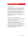
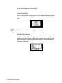
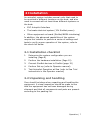
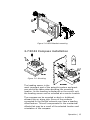
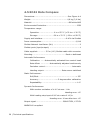
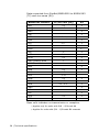
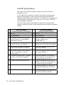
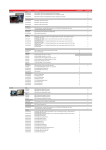
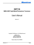
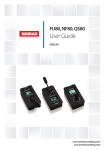
Installation manual
Simrad AP24/28 – EVC,
Volvo IPS Pilot System with
SG05 SimNet-Volvo Gateway
English
www.simrad-yachting.com
A brand by Navico - Leader in Marine Electronics
Installation manual
Simrad AP24/28 – EVC,
Volvo IPS Pilot System with
SG05 SimNet-Volvo Gateway
English
Document no: 20223210
Revision:
A
Date:
May 2008
The original language for this document is English. In the
event of any discrepancy between translated versions
and the English version of this document, the English
document will be the official version.
To the best of our knowledge, the content in this
publication was correct at the time of printing.
As we are continuously improving our products we retain
the right to make changes to the product and the
documentation at any time. Updated manuals are
available from our website www.simrad-yachting.com,
and are free to download.
© Copyright 2008 by Navico Holding AS.
About this manual
Rev. A
08.05.08
First issue
This manual is intended as a reference guide for installing
and maintaining a Simrad autopilot system with the
Simrad SG05 SimNet-Volvo Gateway for Electronic Vessel
Control.
Please take time to read this manual to get a thorough
understanding of the system components and their
relationship to a complete autopilot system.
Important text that requires special attention from the
reader is emphasized as follows:
Used to draw the reader’s attention to a comment or
some important information.
Used when it is necessary to warn personnel that a
risk of damage to the equipment or hazard exists if
care is not exercised.
2 | SG05 Installation manual
Content
1 System description ..................................... 5
1.1 General ..................................................5
1.2 How to use this manual.............................5
1.3 Software record .......................................6
2 Installation ................................................. 7
2.1 Installation checklist .................................7
2.2 Unpacking and handling ............................ 7
2.3 Determine system configuration .................8
2.4 Autopilot system layout.............................9
2.5 SG05 Gateway installation....................... 10
2.6 AP24 and AP28 Control unit installation ..... 11
2.7 RC42 Compass installation ...................... 13
2.8 Interfacing ............................................ 14
2.9 SimNet ................................................. 15
3 Spare parts ............................................... 19
4 Technical specifications ............................ 21
4.1 Autopilot System ................................... 21
4.2 AP24 Control Unit................................... 23
4.3 AP28 Control Unit................................... 24
4.4 SG05 Gateway....................................... 25
4.5 RC42 Rate Compass ............................... 26
4.6 AT10 SimNet/NMEA0183 converter ........... 27
4.7 SimNet ................................................. 29
SG05 Installation manual | 3
4.8 IP protection ......................................... 30
4 | SG05 Installation manual
1 System description
1.1 General
The Simrad SG05 is a gateway for interfacing the AP24
and AP28 autopilot systems to Volvo Penta Electronic
Vessel Control (EVC). It contains the steering computer
and provides interface to other system components.
It communicates on the proprietary SimNet data and
control network to establish a reliable digital
communication and power distribution between the units
in the autopilot system as well as other Simrad products.
SimNet provides high speed data transfer and control of
Simrad products integrated in a total steering and
navigation system.
1.2 How to use this manual
This manual is intended as a reference guide for installing
and maintaining the Simrad SG05 Gateway and other
components in an autopilot system.
Please take time to read this manual to get a thorough
understanding of the system components and their
relationship to a complete autopilot system.
Other documentation material that is provided with your
system includes an operator manual which includes the
setup instructions for the system, a control unit
installation guide and a warranty card. The warranty card
must be filled out by the authorized dealer that
performed the installation.
System description | 5
1.3 Software record
Control units
When the system is switched on, a status display shows
the serial number and software version for the control
unit.
The shown readout is only an example!
SimNet sources
Serial number and software version for other SimNet
sources can be found under the control unit User setup
menu. Refer to Manual source selection in the autopilot
operator manual.
6 | System description
2 Installation
An autopilot system includes several units that need to
be mounted in different locations on the boat, and also
need to connect with at least three different systems on
the boat:
•
EVC Autopilot Interface
•
The boats electrical system (12V SimNet power)
•
Other equipment on board (SimNet/NMEA interfacing)
In addition, the advanced capabilities of the system
require the installer to perform a series of settings and
tests to verify proper operation of the system, refer to
the check list below.
2.1 Installation checklist
1.
Determine the system configuration you are
installing (Page 8)
2.
Perform the hardware installation (Page 10)
3.
Connect SimNet devices to SimNet (page 15)
4.
Perform Set-up (refer to Operator manual)
5.
Test Autopilot Operation at Sea (refer to Sea Trial
instructions in the Operator manual)
2.2 Unpacking and handling
Care should be taken when unpacking and handling the
equipment. A visual inspection should be made to see
that the equipment has not been damaged during
shipment and that all components and parts are present
according to the packing list.
Operation | 7
An autopilot system will include:
•
Control unit (AP24 or AP28) with accessories
•
SG05 Gateway with accessories
•
Compass (RC42) with 5,5 m (18') SimNet cable
attached
•
Optional equipment that may have been ordered for
the installation.
2.3 Determine system configuration
It is important to become familiar with the configuration
of the system prior to beginning the installation. An
autopilot basic single station system with optional station
is shown in Figure 2-1
Plan your cabling and configure the SimNet network in
accordance with chapter 2.9 on page 15.
As most of the units are communicating on a common
network (SimNet) with identical connectors, the
installation is simple. Try to mount the units within the
standard cable length supplied with each unit. SimNet
cables are available from your distributor (see page 20)
for connection to other SimNet devices and cable
extension.
8 | Operation
2.4 Autopilot system layout
AP 24
AP24
Control Unit
AP28
Control Unit
MODE
10
10
1
MENU
TURN
1
AUTO
STB Y
NAV
TURN
WIND
NODRIFT
AUTO
STBY
PWR
MENU
PWR
SG05 Gateway
12V SimNet supply
(SimNet cable with termination)
RC42 Rate Compass
To EVC connect point *
Figure 2-1
AP 24
AP24
Control Unit
AP28
Control Unit
MODE
10
10
1
MENU
AUTO
TURN
1
STBY
NAV
TURN
WIND
NODRIFT
AUTO
STBY
PWR
MENU
PWR
RC42 Rate Compass
SG05 Gateway
12V SimNet supply
(SimNet cable with termination)
To EVC connect point *
Figure 2-2
*
The EVC connect point is a connector on the Volvo
Penta Autopilot Interface kit. It can be ordered from
Volvo Penta under P/N 3819744 (See Figure 2-4).
Operation | 9
2.5 SG05 Gateway installation
•
The SG05 is bulkhead mounted by the enclosed
screws. The SimNet connectors must be pointing
downwards. Figure 2-3.
•
Connect other units according to Figure 2-1. Use only
readymade SimNet cables and accessories. For
SimNet network termination refer to section 2.9 on
page 15.
•
Connect 12V SimNet supply. Refer to Figure 2-10 for
correct polarity
•
Connect the 1 m pigtail plug into mating connector of
the Volvo Penta Autopilot Interface. Figure 2-4
SG05 has a built in LED that will alternate with 1 Hz when
the unit is up running.
Figure 2-3
SG05 mounting
Autopilot Interface kit
(Volvo Penta part number 3819744)
Simrad SG05
Gateway
Autopilot
Gateway
EVC connect point
Y-split
cable
Figure 2-4
10 | Operation
SG05 connection to Volvo Penta Autopilot Interface
2.6 AP24 and AP28 Control unit
installation
Avoid mounting the control unit(s) where it is easily
exposed to sunlight, as this will shorten the lifetime of
the display.
Do not install the control unit where moisture is
present at the rear. It may cause damage by
entering the breathing hole or by coming into
contact with the electrical connectors.
Panel mounting
The mounting surface must be flat and even to within 0.5
mm.
•
Drill the 4 mounting holes and make a panel cut-out
according to supplied template.
•
Connect the SimNet cable(s) to the control unit
connector(s)
•
To daisy chain units remove the blocking plug with a
pair of pliers.
•
Use the supplied 19 mm screws to fasten the control
unit to the panel.
•
Apply the front panel corners.
Do not over-tighten the mounting screws!
Figure 2-5 AP24 Panel mounting
Operation | 11
Optional bracket mounting
Figure 2-6 AP24 Bracket mounting
Figure 2-7 AP28 Panel mounting
12 | Operation
Figure 2-8 AP28 Bracket mounting
2.7 RC42 Compass installation
Figure 2-9 Mounting
The heading sensor is the
most important part of the autopilot system and great
care should be taken when deciding the mounting
location. As the heading is displayed on the control unit,
the heading sensor can be mounted at a remote location.
The compass can be mounted on deck or bulkhead,
athwart ship or along ship. Some of the products
connected to the SimNet network may have a heading
offset feature. This will compensate for the mechanical
offsets that may be a result of the selected location and
orientation of the compass.
Operation | 13
If the connected products have no offset feature, the
compass must be deck or bulkhead mounted athwart ship
with the cable gland pointing back.
Select a location that provides a solid mounting place free
from vibration, and as close to the vessel's centre of roll
and pitch as possible, i.e. close to the water line. It
should be as far as possible from disturbing magnetic
interference e.g. engines (min. 2 meters), engine ignition
cables, other large metal objects and particularly the
autopilot drive unit. On steel hull boats it should be
mounted 0,75-1 m above the wheel house on a non
magnetic stand.
The compass face plate is the TOP. Never mount it upside
down! Level the sensor as close to horizontal as possible.
Use the supplied mounting kit and drill holes through the
centre of the slots.
Connect the compass to an available SimNet connector in
the SimNet “backbone”.
2.8 Interfacing
With the autopilot system there are several possibilities
to connect to other equipment for data collection and
exchange:
1
Use SimNet
2
Use SimNet via AT10 Universal SimNet/NMEA
Converter
3
Connect to a NMEA2000 network via adapter
(drop) cable, part no. 24005729.
The different connecting diagrams on the following pages
illustrate the interface possibilities of the autopilots.
14 | Operation
2.9 SimNet
The SimNet cable system with very small plugs in both
ends makes it easy to run the cables, only 10 mm (3/8”)
holes are required through panels and bulkheads. The
SimNet accessory program contains the necessary items
to make a successful installation. Refer to SimNet
cables and accessories, page 20.
SimNet network cables
A SimNet unit has one or two yellow SimNet connectors.
There are no dedicated “in” or “out” connectors. Route
the SimNet cables with Figure 2-11 or Figure 2-12 as a
guideline. Select cables and accessories from the SimNet
accessory program. Connect products with two SimNet
connectors in a daisy chain and use drop cables and Tjoiners when required. For cable extension in-line cable
joiners are available. Total length of SimNet cable
installed in a system should not exceed 150 meter (500’).
If you plan to extend your SimNet system in the future it
may be advantageous to prepare for it by adding a few Tjoiners in central locations. The T-joiners provide easy
access to the network and can be replaced with a new
product, or the new product can be connected via a drop
cable.
The connectors are weather proof according to IP66,
when properly installed. All unused SimNet connectors
must be fitted with the plastic cap to protect them against
dirt and moisture.
SimNet power and termination
The following rules should be observed when installing
SimNet.
1
It must have a separate 12VDC power from the
battery bus or the circuit breaker board to reduce
interference
2
It will power a SimNet compatible instrument
system. Hence SimNet to other equipment can be
Operation | 15
supplied via the autopilot, see Figure 2-11 and
Figure 2-12.
3
SimNet must be properly terminated, i.e. unless it
is a small system (see Figure 2-1 and Figure 2-2)
there must be terminations at each end of the
Simrad backbone.
The SimNet network has to be terminated according to
the number and type of products connected.
For additional information about SimNet ask for the
separate SimNet Manual.
Figure 2-10 SimNet Power connection
IS20
Instrument
AP24
Control Unit
NX45 NavStation
IS20
Instrument
Wind
transducer *
AP 24
MODE
10
10
1
MENU
AUTO
TURN
1
STB Y
PWR
AT45
RC42
SG05
12V SimNet supply
(SimNet cable without termination)
To EVC connect point
Termination
plug
Multijoiner
Active depth
transducer
Analog
speed/temp
sensor
Figure 2-11 SimNet network, medium system
16 | Operation
GS10
AP28
Control Unit
NX45 NavStation
AP24
Control Unit
IS20
Instrument
IS20
Instrument
Wind
transducer *
AP 24
NAV
TURN
WIND
NODRIFT
AUTO
STBY
MODE
10
10
1
MENU
MENU
AUTO
TURN
1
STB Y
PWR
PWR
AT45
RC42
WR20
RS82
RS82
Black box
SIMRAD RS82
WR20
12V SimNet supply
(SimNet cable without termination)
SG05
WB20
Multijoiner
Analog
speed/temp
sensor
Active depth
transducer
To EVC connect point
Termination
plug
Figure 2-12 SimNet network, expanded system
1.
Maximum total length of SimNet cables is 150 m
(500 ft.)
2.
Drop cables must not exceed 6 m (19 ft) of length
and the total length of drop cables must not exceed
60 m (200 ft).
3.
Equipment should not be daisy-chained in a drop
cable.
4.
The wind transducer (*) has a built in terminator.
Operation | 17
Blank page
18 | Operation
3 Spare parts
AP24 Control Unit
22096614
AP24 Control Unit
22096630
Mounting kit consisting of:
22095483
Cabinet corners (6)
44165181
Screw 3,5x19 (4)
24006355
SimNet blocking plug
22096820
Optional mounting bracket kit
24006355
SimNet blocking plug
22096515
AP24 Weather Cover
AP28 Control Unit
22096622
AP28 Control Unit
22096630
Mounting kit consisting of:
22095483
Cabinet corners (6)
44165181
Screw 3,5x19 (4)
24006355
SimNet blocking plug
22096820
Optional mounting bracket kit
24006355
SimNet blocking plug
22096572
AP28 Weather Cover
SG05 SimNet-Volvo Gateway
24006793
SG05 SimNet-Volvo Gateway w/acc.
24006686
44149292
SG05 SimNet-Volvo Gateway
Screw 3,5x10 (2)
RC42 Rate Compass
22090195
RC42 Rate Compass w/accessories
22081442
Installation Accessories Consisting of:
24006363
20104972
Mounting plate (2)
44140762
Screw 3.5x25 (2)
44140770
Screw 30x9 (4)
22081376
Plug (2)
SimNet Cable, 5.5 m (18’) with one plug
Spare parts | 19
SimNet cables and accessories
20 | Spare parts
24005829
SimNet cable 0.3 m (1’)
24005837
SimNet cable 2 m (6.6’)
24005845
SimNet cable 5 m (16.6’)
24005852
SimNet cable 10 m (33’)
24006363
SimNet cable, 5.5 m (18’) with one plug
24005902
SimNet power w/termination 2 m (6.6’)
24005910
SimNet power w/o termination 2 m (6.6’)
24005729
SimNet to Micro-C male. Adapter cable 0.5
m for SimNet products in a NMEA2000
network.
24005860
SimNet T-joiner (3p)
24006298
SimNet multijoiner (7p)
24005894
SimNet termination plug
44172260
SimNet In-line joiner w/o termination
44172278
SimNet In-line joiner w/termination
24005936
AT10 Universal NMEA0183 converter
AS000469
AT40 NMEA0183 interface to NX40
AA010169
AT45 NMEA0183 interface to NX45
24005878
SimNet cable gland
24005886
SimNet protection plug
24006355
SimNet blocking plug
24005928
SimNet cable protection cap
4 Technical specifications
4.1 Autopilot System
Boat size and type: Up to 50 feet, Displacement, Outboard, Planing
Steering system types:................................... Volvo Penta EVC
Inter-unit connection: ..................................... SimNet network
Maximum number of products connected in a network: .......... 50
System ON/OFF:.......................................... From control units
Supply voltage: ............................................................ 8-16V
Power consumption:.............Dependent on system configuration
EMC protection:.................CE IEC60945 Fourth edition 2002-08
Automatic Steering control:
Rudder Drive: ...................................... Volvo Penta EVC
Parameter selection: ............... Automatic (Autotune) with
manual override
Sea state control:........ Adaptive sea state filter or manual
Language selection: .................Dutch, English, French, German,
Italian, Norwegian, Spanish, Swedish.
NMEA2000 interface:................................. Via SimNet port and
SimNet/NMEA2000 adapter cable
Heading sensor: ....................................... RC42 Rate Compass
Course Selection:....................... Push keys, Rotary knob (AP28)
Alarms: ...................................................... Audible and visual
Alarm modes: ................................. Off course, system failures
Steering modes: ..... Standby, Power steering, Auto, NoDrift, Nav
Special Turn modes: ....... U-Turn, C-Turn, Spiral,Zigzag, Square,
Lazy S, Depth Contour Tracking DTC.
Technical specifications | 21
Instrument data page interface:
Instrument screen
SimNet/NMEA2000 PGN*
Heading
PGN127250, PGN130577
Rudder angle
PGN127245
Speed
PGN128259, PGN129026, PGN130577
Depth
PGN128267
Wind angle, speed
and direction
PGN130306
Position
PGN126992, PGN127250, PGN127258,
PGN129025, PGN129026, PGN129029,
PGN129033, PGN130577
NAV
PGN129283, PGN129284, PGN129285,
PGN129029, PGN129291
Log
PGN128275
Sea temperature
PGN130310, PGN130311
* Parameter Group Number
22 | Technical specifications
4.2 AP24 Control Unit
Dimensions:.....................................................See Figure 4-1
Weight: ..........................................................0,3 kg (0,7 lbs)
Material:........... Front: Black ABS+PC, Back: Dark gray ABS+GF
Supply and interface: .......................................12V via SimNet
Power consumption ....................................................... 1,2 W
SimNet Network load factor (NL): ..........................................2
SimNet ports (input/output): ................................................2
Display:
Type:..................................... Backlit LCD matrix display
Resolution: ............................................ 130 x 79 pixels
Illumination (Red or white):........... Adjustable in 10 steps
Safe distance to compass: ................................. 0.3 m (1.0 ft.)
Environmental Protection:..........IP56 from front, IP43 from back
Temperature:
Operating:........................ 0 to +55 °C (+32 to +130 °F)
Storage:........................ –30 to +70 °C (–22 to +158 °F)
Figure 4-1 AP24 Control Unit – dimensions
(Mounting bracket is optional equipment)
Technical specifications | 23
4.3 AP28 Control Unit
Dimensions:.....................................................See Figure 4-2
Weight: ..........................................................0,5 kg (1.1 lbs)
Material:........... Front: Black ABS+PC, Back: Dark gray ABS+GF
Supply and interface: .......................................12V via SimNet
Power consumption ....................................................... 1,7 W
SimNet Network load factor (NL): ..........................................3
SimNet ports (input/output): ................................................2
Display:
Type:..................................... Backlit LCD matrix display
Resolution: .......................................... 130 x 104 pixels
Illumination (Red or white):........... Adjustable in 10 steps
Safe distance to compass: ................................. 0.3 m (1.0 ft.)
Environmental Protection:.........IP56 from front, IP43 from back.
Temperature:
Operating:........................ 0 to +55 °C (+32 to +130 °F)
Storage:........................ –30 to +70 °C (–22 to +158 °F)
Figure 4-2 AP28 Control Unit – dimensions
(Mounting bracket is optional equipment)
24 | Technical specifications
4.4 SG05 Gateway
Dimensions:.....................................................See Figure 4-3
Weight: ..........................................................0,1 kg (0,2 lbs)
Material:................................................................ Polyamide
Environmental Protection:................................................ IP44
Supply and interface: .......................................12V via SimNet
Power consumption:...................................................... 0.9 W
SimNet Network load factor (NL): ..........................................2
SimNet ports (input/output): ................................................2
Safe distance to compass: ................................. 0.5 m (1.6 ft.)
Temperature range:
Operation: ........................ 0 to +55 °C (+32 to +130 °F)
Storage:........................ –30 to +70 °C (–22 to +158 °F)
Mounting: ......................................................Bulkhead mount
Figure 4-3
SG05 - Dimensions
Technical specifications | 25
4.5 RC42 Rate Compass
Dimensions:.....................................................See Figure 4-4
Weight: ..........................................................0,9 kg (2,0 lbs)
Material:........................................................... Off-white ABS
Environmental Protection:................................................ IP56
Temperature range:
Operation: ....................... 0 to +55 °C (+32 to + 130 °F)
Storage:........................ –30 to +70 °C (–22 to +158 °F)
Supply and interface: ....................................8-16V via SimNet
Power consumption:...................................................... 0,9 W
SimNet Network load factor (NL): ..........................................2
SimNet ports (input/output): ................................................1
Cable supplied:............ 5.5 m (18’) SimNet cable with connector
Mounting: .................................................... Deck or bulkhead
Automatic Performance:
Calibration: ...... Automatically activated from control head
Rate offset: .............. Automatically adjusted continuously
Deviation control:.......................................... Automatic
Heading output: ............................ Rate sensor stabilized
Static Performance:
Roll/Pitch: ........................................................... ± 35°
Accuracy: ............................ ± 3 degrees after calibration
Repeatability: ..................................................... ± 1.0°
Dynamic Performance:
With random excitation of ±10° at max. 1 Hz:
Heading error <2°
With heading step input of 90° at a rate of 10°/s:
Heading error 10 sec after turn <2°
Output signal .......................................... PGN127250, 127251
NMEA2000 compliant
26 | Technical specifications
Figure 4-4
RC42 Rate Compass – Dimensions
4.6 AT10 SimNet/NMEA0183 converter
Technical specifications | 27
Data converted from SimNet/NMEA2000 to NMEA0183
(TX) and vice versa (RX).
NMEA0183 sentence
TX (max rate [Hz])
RX
APB
0.5
x
BWC
0.5
x
BWR
x
DBT
x
DPT
0.5
1
1)
GGA
x
x
GLL
0.52)
HDG
4
x
x
x2)
HDM
HDT
4
HSC
0.1
MTW
x
0.2
x
MWV Relative Wind
1
x
MWV True Wind
1
x
RMA
x
RMB
0.5
x
RMC
0.5
x
RSA
3.33
VHW
0.5
VTG
0.5
VLW
0.2
x
x
1)
0.5
x
VWR
x
WPL
x
XTE
x
ZDA
0.5
ZTG
x
x
Open cells indicates no transmission or reception.
1)
Applies only for units with P/N – S/N code AA
2)
Applies for units with P/N – S/N code BA onwards
28 | Technical specifications
4.7 SimNet
Maximum number of products connected in a network: .......... 50
Maximum cable length: ....................................... 150 m (500’)
Bit rate of the bus:..........................................250 Kbit/second
Maximum DC current through a single SimNet plug................5A
SimNet power supply: .................................................. 12VDC
Maximum drop cable length: ..................................... 6 m (20’)
Maximum total length of all drop cables (accumulated): 60 m (200’)
Environmental protection: Cable and plug/connector system IP66
Maximum temperature: .....................................70 °C (158 °F)
Technical specifications | 29
4.8 IP protection
Each part of a Simrad autopilot system has a two digits IP
protection code.
The IP rating is a method to classify the degree of protection
against solid objects, water ingress and impact afforded by
electrical equipment and enclosures. The system is recognized in
most European countries and is set out in a number of British
and European standards.
The first code number describes the protection against solid
objects, and the second number describes the protection against
liquids.
FIRST NUMBER
Protection against solid objects
SECOND NUMBER
Protection against liquids
IP
TESTS
IP
TESTS
0
No protection
0
No protection
1
Protection against solid objects
up to 50 mm, e.g. accidental
touches by hands.
1
Protected against vertically falling
drops of water (e.g.
condensation).
2
Protection against solid objects
up to 12 mm, e.g. fingers.
2
Protected against direct sprays of
water up to 15° from the vertical.
3
Protection against solid objects
over 2.5 mm (tools + wires)
3
Protected against sprays to 60°
from the vertical.
4
Protection against solid objects
over 1 mm (tools + wires +
small wires)
4
Protected against water sprayed
from any direction.
5
Protection against dust - limited
ingress (no harmful deposit)
5
Protected against low pressure
jets of water from all directions limited ingress permitted.
6
Totally protected against dust
6
Protected against strong jets of
water, e.g. for use on ship decks
- limited ingress permitted.
7
Protected against the effects of
immersion between 15 cm and
1 m.
8
Protected against long periods of
immersion under pressure.
30 | Technical specifications
AP24/28 - EVC, Volvo IPS Pilot System with SG05 SimNet-Volvo Gateway EN, Doc.no.20223210, Rev.A