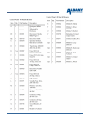
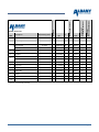
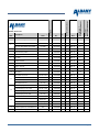
1
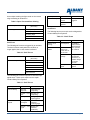
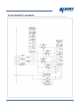
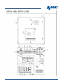
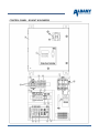
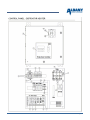
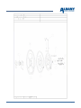
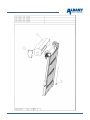
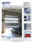
UltraSecureTM
Operations Manual
© Copyright 2007. All Rights Reserved.
Albany Door Systems, Inc. www.albint.com 975 Old Norcross Road Lawrenceville, Georgia 30045
Phone 800-252-2691 Customer Support 877-925-2468 Fax 770-338-5024
INTRODUCTION
The contents of this manual are designed to help you operate and maintain the Rapid Roll™
high-speed doors. DO NOT operate or perform maintenance on the high-speed door
unless you have read through the instructions in this manual.
The safety alert symbol is used to identify safety information about hazards that can
result in personal injury. A signal word (DANGER, WARNING, or CAUTION) is used
with the safety alert symbol to indicate the likelihood and the potential severity of
injury. In addition, a hazard symbol may be used to represent the type of hazard.
DANGER indicates a hazard that, if not avoided, will result in death or
serious injury.
WARNING indicates a hazard that, if not avoided, could result in death or
serious injury.
CAUTION indicates a hazard that, if not avoided, might result in minor or
moderate injury.
CAUTION, when used without the alert symbol, indicates a situation that
could result in damage to the door.
NOTICE is used to inform you of a method, reference, or procedure that
could assist with specific operations or procedures.
Other symbols that may be used in this manual are:
Lock Out / Tag Out
Crushing
Fire
Shock
Read Manual
Your high-speed door is designed to provide years of reliable, low maintenance operation. All operation functions
TM
are controlled through the programmable UltraSmart control panel. The bottom edge of the door provides the
safety capability of reversing the door if it strikes an object and is designed to break away from the side rails if the
door is struck by a vehicle.
Switches in the side tabs of the bottom edge will stop door motion (up or down) if an impact occurs. If an impact
occurs and the door is pushed out of the side rails. If an impact occurs and the door is pushed out of the side rails
TM
the BacFlap Auto-Reset System quickly and easily repairs the door. Pressing the Open keypad on the control
panel will open the door and the door panel will automatically reset itself into the side rails.
TM
Each door is equipped with the BacLight Safety System to prevent injury. Two separate sets of light strips
function as safety controls to prevent the door from closing, or stop the door if it is closing, and any portion of the
light beam is broken by a person or object.
Last Revised: 8/26/2008
Page 2
TOC here.
Last Revised: 8/26/2008
Page 3
RR3000 / 3000L/RR3000R
CONTROL PANEL
Display” on page 4. It is also used when setting
adjustments.
Jog Up: This keypad opens the door at a slower
speed than normal door operation. The door will open
as long as the keypad is pushed.
Jog Down: This keypad closes the door at a slower
speed than normal door operation. The door will
close as long as the keypad is pushed.
Manual Close Delay: This keypad sets the time
delay of the door closing in manual mode. The time
delay is changed (increased or decreased) in onesecond intervals by pressing and releasing the
keypad to display the time delay setting.
Press the
Up Arrow or the
Down Arrow
keypad to change the delay time. If the time is set to
.00., the door will remain open until this activator is
triggered. The display will remain on for four seconds
after this button is released. The set value is
maintained in memory.
Control Panel Keypad
A.
Rotary Disconnect
H.
Reset / Menu
B.
Open
I.
Up Arrow
C.
Stop
J.
Jog Down
D.
Close
K.
Auto Close Delay
E.
Display
L.
Enter
F.
Jog Up
M.
Down Arrow
G.
Manual Close Delay
Disconnect: This switch disconnects the supply
power to the control panel.
Open: This keypad opens the door and stops the
delay timer from closing the door. The timer is started
by pressing the Reset / Menu keypad.
Stop: This keypad stops the opening or closing of the
door.
Close: This keypad closes the door and stops the
delay timer.
Auto Close Delay: This keypad sets the time delay
of the door closing once it has reached the selected
open position in automatic mode. The time delay is
changed (increased or decreased) in one second
intervals by pressing and releasing the keypad to
display the time delay setting.
Press the
Up Arrow or the
Down Arrow key
to change the delay time. The display will remain on
for four seconds after this button is released. The set
value is maintained in memory.
Reset / Menu: This keypad resets error codes. This
button is used while in the program mode to leave the
present level and return to the previous program
level. While in the main menu, this button will exit the
program mode.
Enter: This keypad is used to select menu options
while in the program mode.
Up Arrow
Down Arrow
menu.
: This keypad scrolls up in the menu.
: This keypad scrolls down in the
Display: The display shows operation, functions and
error codes of the door operation. See “Control Panel
Last Revised: 8/26/2008
Page 4
Table 3: Opening
CONTROL PANEL DISPLAY
Top Line
The display on the front of the control panel shows
two lines of information for the operator or service
technician.
Opening – Full
Opening – Part
The top line displays system status and the second
line displays details of the function or specifics of
errors.
NORMAL OPERATION
During startup the display will show the software
version programmed into the control panel and
whether or not the door is ready for normal operation.
Once the software has booted the door is ready for
operation the top line will display “Door Ready”
unless there is a detected error.
During normal operation the top line will display “Door
Ready”, “Opening -- Full”, “Opening -- Part”,
“Closing”, and if a close door delay has been
programmed “Auto1 Close Delay”, “Man1 Close
Delay”, “Man2 Close Delay”, or “DTC Timer”.
The second line on the display will show the activator
name for the function, or the safety device that
triggered a re-open. The activator is the device or
input that triggered an action. The activator can be a
manual input, signal from the light curtain or
reversing edge, or a breakaway switch input.
There can be normal operation with the top line
displaying “Door Ready” and the display second line
showing an warning.
The following tables are normal operation displays:
Bottom Line
(Activator)
Auto 1
Auto 2
Man 1
Man 2
Open PB
Open On Panel
Photo 1 (Front)
Photo 2 (Rear)
Reversing Edge
Breakaway
The "Open: Delay Timer Active" display is shown
when the door is open and a timer function is
operating to delay the door from closing. A
“preventer” code may be displayed if a condition
exists to prevent the door from closing such as a
disruption of the light curtain or a door bottom edge
breakaway. The timer is re-armed if a “preventer”
condition exists.
Table 4: Open Delay Timer Active
Top Line
Auto1 Close Delay
Bottom Line
(Activator)
(Preventer) if any
Auto2 Close Delay
Man1 Close Delay
Man2 Close Delay
DTC Timer
The “DTO Timer” display is shown during a countdown of the timer.
Table 5: Open Commanded: Delay Timer Active
Top Line
Table 1: Startup
Top Line
DTO Timer
Bottom Line
Albany Door Systems
Table 6: Closing
version.n.m
Door Not Ready
Top Line
Table 2: Normal Operation
Closing
Bottom Line
(Activator)
Auto 1
Bottom Line
Auto 2
0000000 The zeros indicate the
number of door operations. The
counter will advance with each full or
partial door opening.
version n.m (shown until first cycle)
Man 1
Top Line
Door Ready
Bottom Line
Last Revised: 8/26/2008
Man 2
Close Pb
Close on Panel
Page 5
If any of the following warnings are displayed except
for “RevEdge Was Tripped”, please contact Albany
Door Systems for diagnosis and repair.
If the bottom line displays “RevEdge Was Tripped” it
indicates that the door is open due to a reversing
edge trip during the previous close cycle.
Seating the Door in the Tracks
In the event that the door bottom bar separates from
a side track, do not attempt to force the bottom bar
end(s) back into the track. The BacFlapTM AutoReset System will reset the door for normal
operation.
Table 7: Normal: Warning
Top Line
Door Ready
Bottom Line
Encoder Low Battery
Module D Loop Open
Module D Loop Short
DO NOT reset the door until the break away
flap(s) are out of the side rails on the side away
from the wall.
Module D Loop Error
Module D Loop1 Open
Module D Loop1 Short
Module D Loop1 Error
Module E Loop2 Open
Pull the bottom rail of the door away from the
wall so the break away flap or flaps are on
the front of the side rails away from the wall.
Note: After the door bottom bar separates from a
side track, when the Open keypad is pressed the
door will open higher than normal operation. It
will open to the break away limit setting.
Module E Loop2 Short
Module E Loop2 Error
RevEdge Was Tripped
OPERATOR SERVICE
Changing the Door Closing Time Delay
In normal operation the Auto time delay selects the
delay time before closing the door once it has
reached the selected open position.
To increase the time that the door waits before
closing:
Press the Auto 1 Close Delay keypad. The
time delay will be displayed in seconds at a
flashing cursor. If no keypad is pressed the
controller will automatically return to normal
operation after approximately 4 seconds.
Press the
Up Arrow or
Down Arrow
keypad to change the time delay in one
second intervals.
After 4 seconds the display will return to normal
operation and the time will be stored in memory. If
the timer is set to “00” with the Man 1 Close Delay
the door will remain open until this activator is
triggered.
Last Revised: 8/26/2008
Press the Open keypad to automatically
FULLY open the door; or, press and hold the
Jog keypad to manually open the door high
enough for the flaps to clear the guides at the
top of the side rails. When using the Jog
keypad DO NOT raise the door higher than
necessary.
Press the Close keypad to close the door.
The bottom bar ends will automatically track
behind the guides and back into the side
rails.
The door control will reset itself to the
automatic mode.
ADJUSTMENTS
Door Limit Adjustments
Door limit adjustments are used to set four heights
that the door opens and closes to. There are four
heights that the operator can set; Closed Limit, Full
Open Limit, Partial Open Limit, and BrkAway Reset
Limit.
The Closed Limit should always be checked for
correct height or set before the other limits are set.
When any limit is set all of the limits should be
checked or set.
Closed Limit: Used to set the fully closed position of
the door. The door controller uses this position as the
“zero” position to establish the height that the door
Page 6
moves to for two open positions and the breakaway
position.
The Open, Partial, and Break Away limits are all
relative to the Closed Limit. If the Closed Limit is
reset to a different position, all the other settings will
change relative to the new Closed Limit setting.
Full Open Limit: Used to set the height that the door
opens fully to.
Use the Jog Up or Jog Down keypads to
move the door up or down so the door lightly
rests on the floor sealing the bottom but does
not compact the bottom edge or allow the
door fabric to lose tension;
Press the Enter keypad to set the limit in
memory. The display will show: Closed Limit.
Press the Up Arrow keypad once to display:
Full Open Limit.
To set the Full Open Limit:
Partial Open Limit: Used to set the height that the
door opens to if it is programmed for a lower opening
in addition to the fully open position.
Break Away Reset Limit: Used to set the height that
the door will open to so the bottom rail can be seated
in the side rails after it has been broken out of them.
This height is set higher than the Full Open Limit.
SETTING DOOR LIMIT ADJUSTMENTS
The fully opened position should keep the door
bottom rail slightly above the wall opening and in
the side rails below the break away set height.
Enter the Limit Setup menu by pressing and holding
the
Up Arrow and
Down Arrow keypads
simultaneously for approximately 5 seconds. The
control display will show:
Limit Setup
Press the Enter keypad when Full Open Limit
is displayed;
Use the Jog Up keypad to move the door up
so the door opens to the desired height. If
necessary, use the Jog Up or Jog Down
keypads for final adjustment;
Press the Enter keypad to set the limit in
memory. The display will show: Full Open
Limit;
Press the
display:
Up Arrow keypad once to
Press the Enter keypad. The control display will
show:
Closed Limit
To set the Partial Open Limit:
Always set the Closed Limit before setting other
limit positions.
The partial open position is typically used with
optional opening switches such as pull cords and
the door opening position is set to approximately
8 feet to allow human passage. It may or may not
be used in normal operation.
If the door closes to the correct position and the
Closed Limit does not need to be changed the
Up Arrow keypad is used to display Full Open
Limit, Partial Open Limit, and BrkAway Reset Limit.
Pressing the Enter keypad when any of the limits are
displayed will allow that limit to be set.
The Reset / Menu keypad can be pressed at any time
to back out of the menu to the next higher level.
When the Limit Setup is displayed pressing the Reset
/ Menu keypad will exit the program and return the
door to normal operation.
To set the Closed Limit:
Press the Enter keypad when Closed Limit is
displayed;
Last Revised: 8/26/2008
If the partial open position is not used, press the
Enter keypad to go to the next procedure to set
the Break Away Limit.
Press the Enter keypad when Partial Open
Limit is displayed;
Use the Jog Down keypad to move the door
down to the desired height. If necessary, use
the Jog Up or Jog Down keypads for final
adjustment;
Press the Enter keypad to set the limit in
memory. The display will show: Partial Open
Limit;
Page 7
Press the
Up Arrow keypad once to
display: BrkAway Limit
full open position. The door will go into a
TIMER EXPIRED fault.
Close Run Timer – This timer is the backup
in case the limit does not stop the door at the
close position. The door will go into a TIMER
EXPIRED fault.
Reverse Delay Timer – This timer will add a
delay to reverse the door if reversed by an
activator or safety device.
Close Delay, Auto 1 – This Auto Close
delay is located on the front of the controller.
Close Delay, Auto 2 – This is the Auto 2
Auto Close used with Mod F (5 Input).
Close Delay, Man 1 – This is the Man 1
Close Delay located on the front of the
controller.
Close Delay, Man 2 – This is the Man 2
Close Delay used with Mod F (5 Input).
Delay to Close, Out P1
Delay to Open, Auto 1
Delay to Open, Auto 2
Door Open Alarm Timer
Air Lock Timer – This timer is used with
Mod J (Air Lock).
Defrost Cycle On – This sets how long the
Tek heat lamps stay turned on (in seconds).
Defrost Cycle Off – This sets how long the
Tek heat lamps stay turned off (in seconds).
To set the Break Away Limit:
The break away opened position should raise the
door bottom rail slightly above the flaps located
at the top of the side rails. The bottom rail should
be able to center itself in the side rails without
reaching the door fabric drum.
Press the Enter keypad when BrkAway Limit
is displayed;
Use the Jog Up keypad to move the door up
to the desired height. If necessary, use the
Jog Up or Jog Down keypads for final
adjustment;
Press the Enter keypad to set the limit in
memory. The display will show: BrkAway
Limit;
Press the Reset / Menu keypad once to
display: Limit Setup;
Press the Reset / Menu keypad once to exit
the menu and return to normal operation.
NAVIGATING THE ULTRASMARTTM
MENU
Once inside the menu of the UltraSmartTM controller,
many options may be used with your door.
Following is a guide for the UltraSmartTM controller:
Limit Setup
Close Limit – Sets the close limit
Full Open Limit – Sets the open limit
Partial Open Limit – Used if a separate
activator will be used to open the door to a
height lower than the Full Open Limit setting.
Breakaway Open Limit – The Breakaway
Open Limit should be set so that the
breakaway tabs are just above the
BacFlapsTM.
Set Timers
Open Run Timer – This timer is the backup
in case the limit does not stop the door at the
Last Revised: 8/26/2008
View Fault History
Entering this menu will show the fault history
of the door, up to the last 64 faults.
Each fault will show the fault / out of how
many total faults. The cycle count when the
fault happened and the fault description.
System Options
Panel Open & Close Disable – Changing
the option from NO to YES will disable the
Open/Close/Stop push buttons on the front of
the control box.
PB & Panel Close Set to Jog only –
Changing the option from NO to YES will
make the Close button on the front of the
control box jog the door only.
Page 8
PB & Panel Open Set to Jog only –
Changing the option from NO to YES will
make the Open button on the front of the
control box jog the door only.
Module G 4 Output – This is an optional
module used when output signals are
needed (example: door is not closed; door is
closed, etc…)
RevEdge Auto Close – Changing the option
from NO to YES will allow the door to Auto
Close when the reversing edge is tripped. If
the reversing edge is tripped 4 times in a
row, the door will stop in the open position
and read “REV EDGE WAS TRIPPED.” The
AutoClose timer controls the AutoClose delay
for this function.
Module H Defrost – This module is used
with the standard freezer package and
controls the heat lamps, blower and has one
output terminal.
Module J Airlock – This is an optional
module used with the Airlock option for the
door.
Photo Eye Auto Close – Changing this
option from NO to YES will allow the door to
AutoClose when the light curtain or photoeye is tripped and the door is not in an
AutoClose or Man1 Close Delay. The
AutoClose timer controls the AutoClose delay
for this function.
Panel Open Man1 Auto Close – Changing
this option from NO to YES will allow the
door to close automatically using the MAN1
delay to close timer. If this option is YES, the
STOP button will not work.
Module Configuration
Module A Activator – This module controls
the inputs for all activators except floor loops.
Module B Safety – This module controls the
light curtains and/or photo-eye inputs along
with the reversing edge and breakaway
switches.
Module C Drive – This module controls the
Variable Frequency Drive (VFD), which
controls the motor. The Emergency Up and
Emergency Down buttons bypass the
UltraSmartTM Controller to operate the door.
THESE BUTTONS WILL NOT STOP AT
THE OPEN AND CLOSED LIMIT
SETTINGS.
ERROR CODES
Error codes are displayed for diagnostic purposes.
Errors fall into basic groups that can be easily
repaired or reset by the operator or must be repaired
by a factory technician.
Safety features designed into the door can typically
be reset by the operator. These include the
breakaway function and situations that prevent the
door from closing. They also include some of the
“soft” or “hard” errors.
Some of the “soft” or “hard” errors require a service
technician for repair.
Breakaway
If a breakaway switch in the bottom rail has been
activated the following errors and instructions will be
displayed. The “Clear Door Request” will display
when there is an input trigger.
To reset the error the bottom rail must be reset in the
side rails. See “Seating the Door in the Tracks” on
page 5 under the OPERATOR SERVICE heading.
Table 8: Breakaway
Module D Loop – This module is an optional
module used for loop detectors.
Clear Door Request
Breakaway
Module E Dual Loop – This module is an
optional module used if separate loop
detectors are required for each side of the
opening.
Bring Panel to Front
Press OPEN or JOG
Module F 5 Input – This is an optional
module in case extra activator inputs are
required.
One of the safety features of the door prevents the
door from closing during normal operation if an
unsafe condition occurs. Causes or “preventers” may
Last Revised: 8/26/2008
Top Line
Bottom Line
Open: Prevented From Closing
Page 9
be an object breaking the light curtain or the reverse
edge contacting an obstruction.
Top Line
Table 9: Open: Prevented from Closing
Top Line
Bottom Line
(Preventer)
Door Ready
Photo 1 (Front)
Photo 2 (Rear)
Reversing Edge
Bottom Line
Door Not Ready
Locked at
Closed
Cause
Lock input
triggered
Locked at
Opened
Hard Errors
The following hard errors require service diagnostics.
Contact Albany Door Systems.
Auto 1
Table 12: “Hard” Errors
Auto 2
Soft Errors
The following soft errors are triggered by an activator.
The door becomes ready when the condition no
longer applies, but no door motion is allowed.
Table 10: “Soft” Errors
Top Line
Bottom Line
(Preventer)
Clear Door Request
Top Line
Bottom Line
Opening “Full”
Closing
Timer Expired
Correct and
RESET
Motor Drive
Fault Cycle
Power OFF for
10 seconds
During
commanded
movement, no
position change
for several
seconds
Door Open
Alarm
Door Open timer
expired
Auto 2
Man 2
The RESET
button must be
pressed before
door operation
can continue
No Encoder
Change
Auto 1
Man 1
Cause
Open Pb
Open On Panel
The following soft errors are specific to detected input
signal errors. These errors require service repair.
Contact Albany Door Systems.
Table 11: “Soft” Errors
Top Line
Door Not Ready
Clear Door
Request
Bottom Line
Cause
Mod x No
Response
I/O Module not
responding
Encoder – Com
Loss
Encoder not
responding
Em Stop
Emergency Stop
input triggered
Rev Edge –
Lost Signal
Broken wire
detected,
reversing edge
BrkAway – Lost
Signal
Broken wire
detected,
breakaway
Last Revised: 8/26/2008
Page 10
PERIODIC MAINTENANCE
Albany Door Systems high speed doors are
engineered for low maintenance operation. The door
should be visually inspected daily for wear and tear,
and operated to verify functions.
Quarterly maintenance should be performed to clean
components and to check all safety functions and
check for mechanical and electrical integrity.
Daily Inspection
1. Inspect the door fabric for wear or damage.
2. Operate the door through several openings and
closings. Verify that the door seats against the
floor and that the door fabric remains tight and
does not wrinkle. Verify that the door opens fully,
slightly beyond the wall opening, and does not
open too far.
If the door does not seat against the floor
properly opens to the wrong position refer to
“Setting Door Limit Adjustments” on page 6.
If the door fabric has diagonal wrinkles the
door fabric roll at the top of the door is not
level and perpendicular to the side rails.
Leveling adjustments should be made as
soon as possible to prevent wear or damage.
Refer to the installation instructions or
contact R-Bac.
7. While the door is closing, tap the bottom of the
door edge and verify that the door stops and
reverses to a fully open position.
Quarterly Inspection
1. Perform daily inspection.
2. Check all mounting hardware and verify that all
nuts and bolts are tight. Hardware includes: wall
anchors, cover hardware, motor mounting
hardware, and bearing bolt nuts.
3. Check the break away function by performing the
following steps:
Stop the door so the bottom rail is between
waist and chest high.
Push the bottom bar out of one of the side
columns.
Press the Open keypad and verify that the
door opens to the break away opening height
and that the bottom bar centers in the side
rails.
Press the Close keypad and verify that the
bottom rail is centered and the door closes
fully.
4. Inspect all side and top weather seals for wear or
damage.
3. With the door closing, place an object through the
light curtain, or photoeyes, on each side of the
door. Verify that the door stops immediately.
4. If a multiple panel door is installed, check the
pins at each end of the ribs to verify that they are
in place and centered.
5. Inspect the coiled electrical wire for wear or
damage.
6. Check the light curtain slots for dirt or dust
accumulation and clean as necessary.
Do not stand under the door when performing the
following inspection. If the bottom bar reversing
switch are not functioning correctly injury can
occur.
Last Revised: 8/26/2008
Page 11
any installation, operation, or maintenance of
the product which does not conform with the
requirements set forth by the seller in the
applicable product manuals or is the result of
any cause other than a defect in the material
or workmanship of the product.
WARRANTY
STATEMENT OF WARRANTY
UltraSeriesTM
Albany Door Systems shall not be
responsible for any other losses or damages
due to the operation of any door or parts
covered by this warranty.
No other oral or written representations made
by Albany Door Systems or its agents are a
part of this warranty unless specifically set
forth in writing by an authorized Albany Door
Systems official.
ONE-YEAR WARRANTY ON MECHANICAL
AND ELECTRICAL COMPONENTS
Albany Door Systems warrants to the
original owner of the door that the
mechanical and electrical components will be
free from defects in material and
workmanship for a period of one (1) year
from date of shipment. The warranty does
not cover fuses, bolts, heat lamps, sleeves,
and seals. The warranty is void twelve (12)
months following the shipment date of the
door.
Only defects brought to the attention of
Albany Door Systems during the warranty
period will be covered by this warranty.
Albany Door Systems will replace
component parts covered by this warranty,
which are found to be defective upon
inspection by an Albany Door Systems
representative. Installation or use of parts
other than those authorized by Albany Door
Systems will void this warranty.
This warranty covers material failure under
normal wear conditions; it does not cover
damage caused by collision or other abuse of
the product. Adjustments made to the control
panel or to the mechanical operation of the
door without the authorization of Albany
Door Systems will void this warranty.
PARTS AND ASSEMBLIES sold separately
by Albany Door Systems that fail due to
defects in material or workmanship within
ninety (90) days from the date of shipment
will be replaced under warranty provided
installation has been carried out in
accordance with all Albany Door Systems
procedures. This warranty is limited to
providing a replacement part only. This
warranty does not cover freight, special
charges, or any costs associated with the
installation of the replacement part.
This warranty shall be void in its entirety if
the failure of any product shall be caused by
Last Revised: 8/26/2008
THE ABOVE SET FORTH WARRANTY IS
SELLER’S SOLE WARRANTY. SELLER MAKES
NO OTHER WARRANTY OF ANY KIND
WHATSOEVER, EXPRESSED OR IMPLIED; AND
ALL IMPLIED WARRANTIES OF
MERCHANTABILITY AND FITNESS FOR A
PARTICULAR PURPOSE WHICH EXCEED THE
AFORESTATED OBLIGATION ARE HEREBY
DISCLAIMED BY SELLER AND EXCLUDED
FROM THIS AGREEMENT.
Page 12
Last Revised: 8/26/2008
Page 13
Last Revised: 8/26/2008
Page 14
SCHEMATICS
Last Revised: 8/26/2008
Page 15
Last Revised: 8/26/2008
Page 16
Last Revised: 8/26/2008
Page 17
Last Revised: 8/26/2008
Page 18
Last Revised: 8/26/2008
Page 19
Last Revised: 8/26/2008
Page 20
Last Revised: 8/26/2008
Page 21
Last Revised: 8/26/2008
Page 22
Last Revised: 8/26/2008
Page 23
Last Revised: 8/26/2008
Page 24
Last Revised: 8/26/2008
Page 25
Last Revised: 8/26/2008
Page 26
Last Revised: 8/26/2008
Page 27
Last Revised: 8/26/2008
Page 28
Last Revised: 8/26/2008
Page 29
Last Revised: 8/26/2008
Page 30
Parts Diagrams and Lists
Last Revised: 8/26/2008
Page 31
Last Revised: 8/26/2008
Page 32
Anzahl pro T
or Quantity per door
I
1
C
Stck./pc.
1
C
Stck./pc.
1
2
4521RG151
C
Stck./pc.
1
Guide cover top LH
4521RG152
C
Stck./pc.
1
Guide cover bottom RH
4521R1101
C
Stck./pc.
1
3
Guide cover bottom LH
4521R1102
C
Stck./pc.
1
4
5
Art-Nr. ItemNo
1
Side frame RH compl.
8220RG215
G
Side frame LH compl.
8220RG216
G
Guide cover top RH
Description
Bemerkung
Note
Side frame right
Side frame left (mirror image)
Guide cover RH
H<2375
4521RG159
G
C
Stck./pc.
1
Guide cover LH
H<2375
4521RG160
G
C
Stck./pc.
1
Gusset cover top RH
4521RG149
G
C
Stck./pc.
1
Gusset cover top LH
4521RG150
G
C
Stck./pc.
1
Gusset cover bottom RH
4521R1099
C
Stck./pc.
1
Gusset cover bottom LH
4521R1100
C
Stck./pc.
1
Gusset cover RH
4521RG163
G
C
Stck./pc.
1
G
C
Stck./pc.
1
C
Stck./pc.
2
C
Stck./pc.
2
C
Stck./pc.
1
C
Stck./pc.
1
Gusset cover LH
4521RG164
6
Spring cover top
4521R0957
7
Spring cover middle
H>3000
4521RG109
Spring cover bottom (side of bearing)
H>3000
4521R0974
Spring cover bottom (side of bearing)
H<=3000
4521RG0111
Spring cover bottom RH (side of unit)
H>3000
4521R0972
C
Stck./pc.
1
Spring cover bottom LH (side of unit)
H>3000
4521R0973
C
Stck./pc.
1
Spring cover bottom RH (side of unit)
H<=3000
4521RG113
G
C
Stck./pc.
1
Spring cover bottom LH (side of unit)
H<=3000
4521RG115
G
C
Stck./pc.
1
8
Tension spring short L=976mm
9
Verschell
Wear part/slitdetaijle
Delivery time class
Pos.
Item
gultig ab
Elnehit
Unit
RR3000, Version 22
Tension spring middle L=1397mm
Tension spring long L=2193mm
10
Spring suspension top complete
11
Belt (blue)
12
Rubber cable curtain tension
Last Revised: 8/26/2008
G
G
H<3000
4802R0009
A
Stck./pc.
max 12
X
3000<=H<4000
4802R0007
A
Stck./pc.
max 12
X
H>=4000
4802R0008
A
Stck./pc.
max 12
X
8220R0050
A
Stck./pc.
4
L=3600
5105R0045
A
mm
4 pc
L=(H-200)x0,6
5105R0009
A
mm
8 pc
Page 33
13
Redirection rope with cable
14
Rope for curtain tension
15
Emergency lever
16
Bowdenhelix d=2,5
17
Brake lever
18
Bowdencable d=1,5
19
22
Stck./pc.
2
A
mm
2 pc
B
Stck./pc.
1
5006RG218
A
mm
1
5005R0023
A
Stck./pc.
1
5006R0007
A
mm
1
8120RG046
G
5105R0037
8220RG218
L=800
L=H+500
G
A
Stck./pc.
1
Bottomplate LH
4521R1065
A
Stck./pc.
1
B
Stck./pc.
2
Cable Chain complete
(*)
8520RG002
Connecting cable 4m
drive side
H<=2500
4907R0024
A
Stck./pc.
1
Connecting cable 6m
drive side
2500<H<=4500
non drive side
(H+B)<=4500
4907R0029
A
Stck./pc.
1
Connecting cable 8m
drive side
H>4500
non drive side
4500<(H+B)<=8500
4907R0030
A
Stck./pc.
1
Connecting cable 10m
non drive side
6500<(H+B)<=8500
4907R0032
A
Stck./pc.
1
Connecting cable 12m
non drive side
8500<(H+B)<=10500
4907R0023
A
Stck./pc.
1
Connecting cable 14m
non drive side
10500<(H+B)<=12500
4907R0031
A
Stck./pc.
1
Belt receptacle
8120R0047
A
Stck./pc.
2
Proximity switch M8 10E Plugconnector
4905R0082
A
Stck./pc.
1
4907r0044
A
Stck./pc.
1
4905R0082
A
Stck./pc.
1
Driveside
4907r0044
A
Stck./pc.
1
L=2000
8120R0049
B
Stck./pc.
4
Driveside
Proximity switch M8 10E Plugconnector
Connecting cable 2m with 2 M8 plugs
G
24
Cable Duct complete
25
Spring Suspension
4521R1090
A
Stck./pc.
6
Sliding rail 3000 mm long
4121R0335
A
Stck./pc.
18
Tapping screw 4,2x9,5
5406R0241
A
Stck./pc.
12
27
Rope pulley
5003R0001
A
Stck./pc.
8
28
Choise label emergency lever
6403R0009
A
Stck./pc.
1
29
Door label
6403R0004
A
Stck./pc.
1
26
Verschell
Wear part/slitdetaijle
A
1
4521R1064
Connecting cable 2m with 2 M8 plugs
23
L=H+850
Elnehit
Unit
Art-Nr. ItemNo
Bottomplate RH
20
21
Bemerkung
Note
Anzahl pro T
or Quantity per door
Description
Delivery time class
Pos.
Item
gultig ab
RR3000, Version 22
(*) Data of W, H and drive side is necessary
Last Revised: 8/26/2008
Page 34
Last Revised: 8/26/2008
Page 35
II
1
8230RG032
G
B
m
isolation with Polystyrol
m
Lamella 1 with extension piece 1-short
8230RG029
G
B
max 10
m
isolation with Polystyrol
m
isolation with mineral wool
m
H<=3125: n=(H-1500)/125
H>=3125: n=13
8230RG030
G
B
max 13
without isolation
m
isolation with Polystyrol
m
isolation with mineral wool
m
Lamella 3 with extension piece 3-long
4
m
H<=4000: n=10
H>4000: n=7
without isolation
Lamella 2 with extension piece 2-middle
3
1
without isolation
isolation with mineral wool
2
Elnehit Unit
Panel Door Blade Type 1
Top lamella, with intel sealing
1
Art-Nr.
Item-No
H>3250: n=(H-3125)/125
8230RG031
G
B
max 15
without isolation
m
isolation with Polystyrol
m
isolation with mineral wool
m
5
Window lamella 1 with extension piece
1-short
H<=4000: n=10
H>4000: n=7
8230RG033
G
B
m
max 8
6
Window lamella 2 with extension piece
2-middle
H<=3125: n=(H-1500)/125
H>=3125: n=13
8230RG034
G
B
m
max 8
7
Window lamella 3 with extension piece
3-long
H>3250: n=(H-3125)/125
8230RG035
G
B
m
max 10
8230RG036
G
B
Bottom lamella with rubber profile
without extension piece 4
8
9
Verschell
Wear part/slitdetaijle
Bemerkung Note
Anzahl pro T
or Quantity per door
Description
Delivery time class
Pos.
Item
gultig ab
RR3000, Version 22
1
without isolation
m
isolation with Polystyrol
m
isolation with mineral wool
m
Extension piece 1, short
H<=4000: n=10
H>4000: n=7
4521R1063
A
Stck./pc.
max 22
4521R0878
A
Stck./pc.
max 26
4521R0878
A
Stck./pc.
max 30
10
Extension piece 2, middle
H<3125: n=(H-1500)/125
H>3125: n=13
11
Extension piece 3, long
H>3250: n=(H-3125)/125
Last Revised: 8/26/2008
Page 36
Art-Nr.
Item-No
1
Elnehit Unit
12
Extension piece 4 re, for bottom lamella
8150R0064
A
Stck./pc.
1
13
Extension piece 4 li, for bottom lamella
8150R0065
A
Stck./pc.
1
14
Clamping lug standard
4521R0966
A
Stck./pc.
max 78
15
Clamping lug extension piece 4
H>3250
4521R1028
A
Stck./pc.
max 2
16
Connecting lug extension piece 4
H<=3250
4521R1069
A
Stck./pc.
max 2
17
Lamella sealing
4402RG005
B
m
200
18
Sealing top lamella
4421RG011
B
m
6
Bottom rubber profile
4402RG006
B
m
6
Rubber profile extended sealing lip cutto-size
4421RG016
C
m
4121R0299
B
Stck./pc.
max 2
4904R0211
A
Stck./pc.
1
Photocell receiver
4904R0477
A
Stck./pc
1
Bracket pre running photocell RH
4521R0943
A
Stck./pc
1
Bracket pre running photocell LH
4521R1023
A
Stck./pc
1
Activator Proxilimity switch RH
4521R0981
A
Stck./pc
1
Activator Proxilimity switch LH
4521R0982
A
Stck./pc
1
Flat belt repair-kit
8130R0011
A
Stck./pc.
19
20
21
22
23
Flat belt L 6000 mm
Photocell transmitter
LH
G
Verschell
Wear part/slitdetaijle
Bemerkung Note
Anzahl pro T
or Quantity per door
Description
Delivery time class
Pos.
Item
gultig ab
RR3000, Version 22
(*) Inclusive lamella seal (position 17), without clamping plate (position 14-16)
Last Revised: 8/26/2008
Page 37
Last Revised: 8/26/2008
Page 38
1
H<=3250
8240RG100
G
H>3250
8240RG100
G
Elnehit
Unit
D
Stck./pc.
1
D
Stck./pc.
1
Barrel complete
Barrel complete
1
Spiral disk 1
4521R0940
A
Stck./pc.
2
2
Spiral disk 2
4521R0939
A
Stck./pc.
2
Spiral disk 3 LH
H>3250
4521R1048
A
Stck./pc
1
Spiral disk 3 RH
H>3250
4521R1047
A
Stck./pc
1
4
Dampener disks
L=1850
4401R0002
A
m.
10
5
Bearing d 35
8140R0060
A
Stck./pc.
2
6
Bracket belt
4521R0953
A
Stck./pc.
2
7
Winding plate
4521R0941
A
Stck./pc.
2
8
U-Bracket
4521R1179
A
Stck./pc.
max 12
9
Bracket cam
4521R1167
A
Stck./pc.
max 12
10
Barrel without components
4521RG103
C
Stck./pc
1
3
Verschell
Wear part/slitdetaijle
Art-Nr. ItemNo
Bemerkung Note
Anzahl pro T
or Quantity per door
III
Description
Delivery time class
Pos.
Item
gultig ab
RR3000, Version 22
G
(*) Data of W, H and drive side is necessary
Last Revised: 8/26/2008
Page 39
Last Revised: 8/26/2008
Page 40
IV
1
Gear motor 220-230/400-415 V 50Hz
H>4000
6601R0083
B
Stck./pc.
1
Gear motor 220-230/400-415 V 60Hz
H<=4000
6601R0010
B
Stck./pc.
1
Description
Bemerkung
Note
Art-Nr. ItemNo
1
Drive Unit complete
2
Brake 15Nm 196V DC HL
6622R0018
A
Stck./pc.
1
3
Double Proximity Switch
4905R0019
A
Stck./pc.
1
4
Torque arm
4521R0776
A
Stck./pc.
1
5
Motor plate
4521R1096
A
Stck./pc.
1
6
Vibration absorber
5004R0041
A
Stck./pc.
2
7
Microswitch
6621R0002
A
Stck./pc.
1
8
Spring 2, 2x11x48
4802R0004
A
Stck./pc.
1
9
No.-cable 4x1,5
4907R0020
A
mm
1 pc
10
Cable 2x0,75
4907R0018
A
mm
1 pc
11
12
Verschell
Wear part/slitdetaijle
Anzahl pro T
or Quantity per door
Delivery time class
Pos.
Item
gultig ab
Elnehit
Unit
RR3000, Version 22
Cable 4x0,25 11,5m GY
5m<SL<=10m
4907R0026
A
Stck./pc.
1
Cable 4x0,25 21,5m GY
10m<SL<=20m
4907R0027
A
Stck./pc.
1
Cable 4x0,25 31,5m GY
20m<SL<=30m
4907R0028
A
Stck./pc.
1
Cable 4x0,25 6,5m GY
SL<=5m
4907R0025
A
Stck./pc.
1
Junctionbox 9plug 11,5m cable
5m<SL<=10m
4906R0028
A
Stck./pc.
1
Junctionbox 9plug 21,5m cable
10m<SL<=20m
4906R0029
A
Stck./pc.
1
Junctionbox 9plug 31,5m cable
20m<SL<=30m
4906R0030
A
Stck./pc.
1
Junctionbox 9plug 6,5m cable
SL<=5m
4906R0027
A
Stck./pc.
1
Control cable
ACS 80
8830RG042
B
13
1
Base price
Stck./pc.
Upcharge
m
Control Cable
MCC
8830RG048
B
Stck./pc.
1
14
Encoder 50 pulses for motor MW1100
MCC
4904R0448
A
Stck./pc.
1
15
Encoder, electronic part
MCC
4904R0450
A
Stck./pc.
1
Last Revised: 8/26/2008
Page 41
Last Revised: 8/26/2008
Page 42
V
Top roll cover
G
Verschell
Wear part/slitdetaijle
8260RG033
Elnehit
Unit
1
Base price
Stck./pc.
Upcharge
m/W
Motor Cover RH
8160R0036
Stck./pc.
1
4907R0027
Stck./pc.
1
8160R0071
Stck./pc.
1
Motor Cover LH
8160R0072
Stck./pc.
1
2. emergency lever (option)
8170RG022
G
Stck./pc.
1
Transport pallet
8270RG031
G
Stck./pc.
1
Plastic
>01/2007
Motor Cover LH
Motor Cover RH
3
1
Options
1
2
Art-Nr. ItemNo
Anzahl pro T
or Quantity per door
Bemerkung
Note
Description
Delivery time class
Pos.
Item
gultig ab
RR3000, Version 22
Alu
02/2007>
SL = control line
H, L => [mm]
Legend
1
G
Generic Item
A
Within 24 hours
Delivery Time
B
2-3 workdays
C
5-8 workdays
D
10-14 workdays
x
Standard wear with time/use
Wear Parts
Last Revised: 8/26/2008
Page 43
. www.albint.com 975 Old Norcross Road Lawrenceville, Georgia 30045
Phone 800-252-2691 Customer Support 877-925-2468 Fax 770-338-5024