1
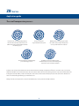
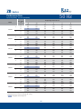
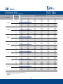
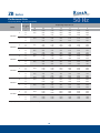
ZB Refrigeration Scroll Compressor Catalogue
ZB Series
Index
General Information
1-1
Features
2-2
Application guide
3-11
Installation and piping arrangement
12-14
Performance Data
15-29
R22
R404A
R134a
R22
R404A
R134a
15-16
17-18
19-20
21-23
24-26
27-29
50Hz
50Hz
50Hz
60Hz
60Hz
60Hz
Technical Data
30-31
Dimensions & Brazing Connection
32-39
ZB15-ZB26
ZB30-ZB45
ZB50-ZB58
ZB66-ZB88
ZB92
ZB11MC
32-32
33-33
34-35
36-37
38-38
39-39
Electrical Wiring Diagram
40-43
ZB15-ZB88
ZB92-ZB11M
40-41
42-43
Application Envelope
44-44
Model Nomenclature & BOM Summary
45-45
ZB Series
General Information
Copeland Corporation was established in 1921 in Detroit City, Michigan State, U.S.A. For more than 80 years, it has been our endeavour to bring
cutting-edge products to create a healthy environment and safeguard food.
A Brief Timeline of Achievements:
* first household refrigerator in the world, in 1921;
* first semi-hermetic compressor in the world, in 1941;
* first semi-hermetic compressor with butterfly valve in the world, in 1979;
* first scroll compressor with dual compliance, in 1987;
* first digital scroll compressor in the world, in 1996;
* first commercial large horse power scroll compressor in the world, in 2001;
* first electronic-display scroll compressor-condensing unit in the world, in 2002;
* first digital scroll heating in the world, in 2004
Today, Emerson Climate Technologies continues to lead the global industry of refrigeration and air-conditioning compressors- with annual sales
of over 2 billion dollars, technical service network spanning 120 countries and the largest compressor R&D centre in the world. Our global
customers include highly reputed refrigeration and air-conditioning equipment manufacturers, supermarket chains, fast-food chains, hospitals,
restaurants, laboratories, factories and schools. We constantly endeavour to provide you with high-quality compressors and after-sales service.
The introduction of scroll compressor in 1987 has revolutionized the refrigeration industry. The scroll compressor has several unique advantages:
high energy-efficiency ratio, low noise level, high reliability and running cost. This revolutionary technology is being successfully used by
manufacturers, dealers and end-users. To date, the number of scroll compressors manufactured by Emerson Climate Technologies has crossed
the 40-million mark.
Scroll compressors have been successfully used in the air-conditioning industry, and the future of refrigeration belongs to the scroll compressor.
ZB92KC~ZB11M
ZB50KQ~ZB88KQ
ZB30KQ~ZB45KQ
ZB15KQ~ZB26KQ
2
HP
5
HP
10
HP
15
HP
Emerson's range of ZB Series of scroll compressors
1
ZB Series
Features
Dual Compliance
High-efficiency "Teflon" bearings:
This design ensures good sealing between the scroll spirals. It
High Efficiency "Teflon" is used for
allows the scroll spirals to contact and separate along the radial
the upper main and drive bearing.
and axial directions. Debris or liquid can go through the scroll disks
"Space age" materials used in the
without damaging the compressor. This results in:
compressor include:
* longer lifetime and better reliability
(1) Porous bronze
* better liquid handling capability
* better handling of debris
(2) PTFE-lead overlay
2
1
Crankshaft
There is exceptionally low friction.
This also allows for extended
Fixed scroll
Axial compliance
operation without lubrication.
Orbiting
scroll
Copeland refrigeration scroll compressors offer outstanding
solutions for medium and high temperature applications. ZB
Series of refrigeration scroll compressors are ideal for compact
system designs that require a high degree of reliability and
Radial compliance
energy-efficiency. Available ZB Series is in the range of 2-15HP.
Applicable refrigerants include R22, R404A, R507 and R134a.
Designed for high energy-efficiency:
The scroll spirals in a scroll compressor wear in, rather than wear
Refrigerating capacity data
out. Over time, the wear-in improves performance. This ensures a
Refrigerating capacity data listed in this manual are applicable for
very high volumetric efficiency.
power frequencies of 50Hz (speed of motor equals 2900rpm) and
60Hz (speed of motor equals 3500rpm). The scope of compressor
operation should not exceed listed conditions.
Designed for lower noise and vibration:
The scroll design creates a smooth sound spectrum and better
sound quality. The layout of the compression chambers is
symmetric, making for very minimal imbalances. Manufacturing
All specifications in this catalogue are subject to change without
accuracy of scroll compressors is quite high. Scroll compressors do
notice.
not normally require any vibration-absorbing device.
"Unloaded Start" technique
After shut down, the two scroll forms are separated from each
other. This enables full internal pressure equalization at shut down.
For this reason, additional start capacitors are not normally
necessary at start-up of single phase models.
2
ZB Series
Application guide
The scroll compression process :
Compression is accomplished by reducing
the size of the outside pockets as the scroll
relative motion moves them inwards towards
the discharge port
Orbiting motion moves the gas toward
the center of the scroll pair and pressure
rises as pocket volumes are reduced
Suction is sealed off
as gas is drawn into the spiral.
2
3
1
The gas reaches the central discharge
port at discharge pressure
5
6
4
Six distinct compression paths operate
simultaneously in a scroll set. The discharge and
suction processes are nearly continuous
A simple scroll concept was first invented in 1905. As shown in the above drawing, a Copeland Scroll® has two concentric scrolls, one inserted
within the other. One scroll remains stationary as the other orbits around it. This movement draws gas into the compression chamber and moves
it through successively smaller "pockets" formed by the scroll's rotation, until it reaches maximum pressure at the center of the chamber from
where it is released through a discharge port in the fixed scroll.
During each orbit, several pockets are compressed simultaneously- so the operation is virtually continuous.
3
ZB Series
Application guide
Configuration of the scroll compressor
Type of compressor
Built-in pressure
relief valve
Discharge temperature
protection
Unidirectional discharge
valve
Motor protection
ZB15-ZB45
IPR
TOD
Yes
Neutral protection
ZB50-ZB88
IPR
ASTP
Yes
Neutral protection
ZB92-ZB11M
NA
Built-in sensor
for discharge temperature
NA
External protection
module of motor +
Built-in sensor
Internal Pressure Release valve (IPR)
Motor protection module
A built-in relief pressure valve is mounted between the high-
Both ZB92 and ZB11M motor protection systems include an
pressure and low-pressure side of the compressor. If the pressure
external protection module for the motor. The module is connected
difference between the high- and low-pressure exceeds 26-32bar,
with four thermistors in series built into the motor windings and a
the internal pressure release valve opens. At the same time, the
fifth thermistor mounted at the internal discharge port of the scroll
hot discharge gas comes in contact with the temperature sensor
disks. If either motor or discharge temperature exceeds the limit
of the motor protector. As a result, the internal motor protector
value, the module will trip and can only be reset after 30 minutes.
trips. Once the compressor has cooled, the motor protector can
(Note: if the power supply of the module is cut off, the module will
be reset.
reset at once.) The time-delay is set at 30 minutes in order for the
scroll compressor to cool down fully. If the compressor is restarted
Models ZB92 and ZB11M do not have the in-built pressure relief
without a time-delay, a destructive temperature-surge will be
valve. In order to ensure safe operation, the system configuration
caused in the compressor. For this reason, the power supply of the
should include a high-pressure switch whose setting pressure
module must not be clubbed together with the control circuit (see
does not exceed 30bar (gauge pressure).
also the schematic wiring diagram).
Internal temperature protection
Therm-O-Disc (TOD) or ASTP is a temperature-sensitive snap disc
device installed at the scroll outlet. If the discharge temperature is
excessively high, the valve will open to allow the hightemperature suction gas to return and contact with the motor
protection, so as to protect the compressor.
4
ZB Series
Application guide
Field troubleshooting of the motor protection module
Diagnose resistance readings according to the following data:
Cut-off the power supply of the control circuit, and bypass the
- 150-2250: normal running range;
motor protection module. Remove the conductor of the control
- 2750: the compressor superheats: rest the compressor for a
circuit from M1 and M2 terminals of the module, and connect a
sufficiently long period to allow it to completely cool down;
jumper wire to bypass the control circuit of the module. (Note:
- 0: the sensor has been short-circuited, change the compressor;
thus far the motor protection module inside the compressor has
- : the sensor circuit is cut-off, change the compressor.
been bypassed, but this method can only be used to test the
If the resistance readings are outside the range of normal values,
module.)
pull out the connector plug on the sensor and measure the
resistance at the sensor terminals. One can determine the reason
Switch on the control circuit and the power supply of the module
why the readings are not normal and establish whether the fault lies
again, and commission the compressor: if the compressor does
with the connector or thermistor.
not operate when the module is by-passed, the fault is not in the
control system and the module. If the compressor operates
After compressor start or any module trip, the resistance of the
when by-passing the module, but fails to operate by connecting
sensor series must be below the resetting point of the module
the module again, the relay in the control circuit of the module is
before it closes again. Its resetting value equals 2250-3000. If the
undoubtedly cut-off. Now, the thermistors' series must be tested
resistance of the sensor series is below 2250 and the compressor
in order to determine the reason why the relay in the control
cannot be put into operation through by-passing the control circuit,
circuit of the module is cut-off: either the internal temperature is
it indicates solid-state module damage and should be exchanged.
too high or elements in the control circuit are faulty.
During the test period, the voltage should be cut-off to prevent
Check the thermistors' series:
short-circuit and accidents at the contacts. Whenever the circuit
Cut-off the control circuit and the power supply of the module,
breaker disconnects or trips, the module function should be
and remove the lead wire of the sensor from S1 and S2 terminals
checked, to ensure that the module contacts haven't been bound.
of the module, and measure the resistance of the thermistor
series via the sensor by means of an ohmmeter. (Caution: use an
ohmmeter of 9V maximum resistance to check the series; the
sensor is sensitive and vulnerable; do not try to check the
electrical conductivity of the sensor by means of any nonresistance tools; do not apply any external voltage to the sensor the compressor could be damaged and may even have to be
replaced.)
5
ZB Series
Application guide
Minimum operating time
The number of times a compressor can start and stop within a period of one hour depends on the system configuration to a great extent. By
nature, the scroll compressor starts unloaded; therefore the minimum operation time is not specified. The quantity of lubricating oil that
returns to the compressor at start is, however, a critical measurement. The simplest is by means of the sight glass (optional item), but the
longest piping permitted for the system should be connected at the time of this measurement.
The minimum operation time means the time necessary for the normal oil level in the sight glass to be restored from compressor start-up to
shut-down. If the compressor start-stop cycles are shorter than the minimum operation time, for example, to maintain exact temperature
control, the compressor will gradually lose the lubricating oil and may even be damaged. For more information on compressor start-stop cycle
and frequency, see the engineering application manual numbered 17-1262.
Accessories
Discharge temperature protection
If the system design does not ensure compressor operation within the range specified or if the system layout is not reasonable, very high
discharge temperature could be caused, thereby leading to carburization of the lubricating oil, irregular compressor operation or even
compressor failure. A Discharge Temperature Controll (DTC) valve should be installed in the system.
The DTC valves supplied by Emerson are as below. The control circuit will be cut off when the discharge temperature exceeds 126oC.
Compressor Models
ZB15-ZB45
ZB50-ZB88
DTC type
Lead wire terminals
Alarm interface
998-0540-00
NA
NA
998-0548-00
NA
Yes
998-7022-02
Yes
Yes
998-0540-03
Without lead wire
NA
998-7022-05
With lead wire
NA
Suitable pipe size
1/2''
7/8''
When the compressor is not equipped with a block valve, the DTC is installed at a distance of 178mm from the outlet. When the
compressor is equipped with a block valve, the DTC is installed at a distance of 127mm from the outlet. When installing the block valve,
the DTC should adhere to the surface of the discharge pipe, and should be fixed by means of the clamp supplied with the assembly.
Copeland DTC can be connected with 120V or 240V control circuit.
6
ZB Series
Application guide
Crankcase heater
Gas-liquid separator
Single-phase scroll compressor does not require installation of
Copeland scroll compressor has a greater capacity to resist liquid because
a crankcase heater.
of some inherent characteristics. It is possible that the gas-liquid
separator does not need to be used in most of the systems. However, it is
When the refrigerant charge exceeds the values listed in the
suggested that the gas-liquid separator be used when:
following table, or, when the refrigerant is charged at-site, a
* a large quantity of the liquid refrigerant in the system returns
continuously into the compressor within a period of regular stop
crankcase heater is necessary for the three-phase compressor.
Compressor Models
Refrigerant Charge(kg)
ZB15-ZB45
4.5
ZB50-ZB88
7.2
ZB92-ZB11M
7.7
* there is defrosting
* there is a variable load regardless of the charged quantity of refrigerant
in the system
* it is impossible to control the liquid-return phenomenon or wet start
because of the dilution of lubricating oil
If the gas-liquid separator is used in the system, it is suggested that the
40
dimension of the return oil orifice should be within 1-1.9mm. Also, the
filtering area of the protecting screen should be large enough, and its
mesh size not below 30x30 (diameter of 0.6mm). It is not advisable to use
Installation of the crankcase heater
screen finer than 30x30 mesh in the system anywhere in order to protect
the orifice from being blocked by debris.
Drying filter and humidity indicator
Pressure controller
The filter drier installed in the liquid piping should be large enough and
To ensure the safe operation of the refrigeration system, Emerson
adequate for uninterrupted operation. The dehumidifier should be
suggests that all systems be equipped with high- and low-pressure
selected according to the flow rate of the refrigerant. Do not use
switches.
dehumidifiers that can turn into liquid state after absorbing a large
quantity of wet steam, such as potassium chloride. It is suggested that
See the following table for the recommended setting values (unit:
porous block dehumidifiers are used to absorb the wet steam or acid and
bar, gauge pressure).
prevent metal fragments from invading. The filter drier should be
installed after a second vacuum operation has been carried out. The sight
glass for the humidity indicator should be installed in a clearly visible
Control type
R22
R404A/507
R134a
High pressure (maximum)
26
30
18
position on the liquid piping, in order to facilitate the checking of
Low pressure (minimum)
1.7
1.15
0.3
refrigerant flow rate.
7
ZB Series
Application guide
Filter for the suction piping
To avoid compressor faults, all impurities (fouling products, welding scale, borax and metal fragments etc.) must be removed from the system
before start of operation. The impurities can go into the compressor suction area even through the micro filter because of the extremely fine
size of impurities. When the assembly is carried out at-site and the necessary cleanliness cannot be ensured, it is suggested that a highcapacity filter is used for the suction (there is only a very small pressure drop). A pressure gauge should be placed before the filter to detect the
pressure drop arising from the filter.
Oil separator
When installing the oil separator, it must be charged with the lubricating oil until the valve begins to open. The oil quantity in the oil separator
should be maintained at all times. If not, the oil in the compressor will be drawn off by the oil separator; consequently the oil quantity will
decrease gradually.
Refrigerant and oil
The refrigerants R22, R404A, R507 and R134a etc. can be used in ZB Series scroll compressors. If any of the environmentally-friendly
refrigerants, namely, R134a, R404A, R507 etc. are used, an ester lubricating oil must be used (POE oil). The residual water content in a system
charged with POE oil must be below 50ppm. This is because of the highly hygroscopic nature of ester oil. Such a measurement can be carried
out only after the system has run for 48 hours. A good filter-drier of large capacity may be installed according to the system and refrigerants.
At the time of commissioning, an appropriate capacity of vacuum-pump must be selected. Parts used with the system must be selected
keeping in mind the characteristics of the refrigerant (consult with the part manufacturer about details). These include:
Expansion valves
Filter-Dryer
Valves, fittings and control devices.
These would change depending upon the change of the mass flow rates of refrigerants.
8
ZB Series
Application guide
Oils
Mineral oil is not adaptable for systems working with the new refrigerants, because it is not compatible with this kind of refrigerant. It has already
been verified that POE lubricating oil can replace mineral oil. To ensure a long working life, the performance characteristics of polyester oil must be
specifically noted. Only certified ester oils may be used with the new refrigerants R404A, R134a, R407C and R507. They should be mixed according
to specified guidelines. To prevent the mineral oil and the polyester oil from polluting each other, the devices for traditional refrigerants and new
refrigerants, such as vacuum-pump, pipe fittings, charge and reclamation equipment and other parts should be clearly distinguished and serviced.
Poly Ester Oil has a very strong hygroscopic property. The chemical stability of the lubricating oil will be affected if it draws in moisture. During
storage and transportation, the compressor is charged with dry nitrogen to prevent the penetration of moisture. During installation, the exposure
of the compressor outlet should be minimized in every possible way.
Ester oils certified by Copeland:
EAL Arctic 22CC, Mobil Co.;
Mineral oils certified by Copeland:
Suniso 3GS, Sun Oil Co.;
Emkarate RL 32CF, ICI Co.
Capella WF32, Chevron/Texaco Co.
Please see also Copeland operating instruction manual AE17-1248 for details of Copeland-approved lubricating oils. System manufacturers should
provide data for refrigerants on the nameplate.
Typical layout of suction piping
As short as possible
(See note 6)
Suction pipe
Drying-filter for
suction pipe
<0.5m
<0.5m
<0.5m
Uninterrupted piping (without any elbow)
9
Notes:
1. The purpose of the above-mentioned piping
layout is to decrease the stress in the piping.
2. Design of discharge and return oil piping
should also comply with this principle.
3. If the length of pipe exceeds 0.5m, measures
should be taken to fix it.
4. If there is a heavier load on the piping (such as a
filter-drier), due care should be given to fixing.
5. It is advised that the length of the pipe not drop
below 0.2m.
6. Piping sections should be small as far as
possible (50mm or shorter). At the same time,
adequate welding length should be ensured.
7. Copeland does not recommend using an elbow
to connect piping sections, and recommends
using copper tubes without joints or turns.
ZB Series
Application guide
Installation and piping arrangement
Pipeline
Installation of the compressor should be done according to the
During installation, great care should be taken to keep the
service conditions. The selected installation and piping design
piping lines of the refrigerating equipment extremely clean. In
should dampen the transmission of noise and vibration as far as
principle, the refrigerating equipment should always have clean
possible. Please see also the following table for tightening torques:
and dry pipelines, and there should not be any scale, rust and
phosphate layer on it. Dry nitrogen must be charged in the
pipeline during welding. To prevent the welding joints in the
Reference table for tightening torque
Torque (N.m)
pipeline from producing foul, the welding temperature must be
Rotalock screw valve 3/4''-16UN
40-50
carefully controlled. The welding operation should not be
Rotalock screw valve 1 1/4''-12UN
100-110
carried out on pipeline that contains refrigerant (even if the
Rotalock screw valve 1 3/4''-12UN
170-180
refrigerant is not under pressure), because the heating of
Rotalock screw valve 2 1/4''-12UN
190-200
refrigerant, oil and air will form a toxic gas. The pipeline design
Flange with M16 stud
102-113
must ensure that, even at part load, the lubricating oil returns
Oil level sight glass
25-25.5
to the compressor despite low gas flow velocity in the suction
5/16'', M9 installation stud
Maximum 27
and discharge pipes.
Soft foot
12-14
Connecting screw in terminal box
2.5-2.6
Mounting
The single-compressor-condenser unit makes use of soft rubber
grommets for mounting. When the compressors are used for
tandem operation, they are mounted by means of steel spacers or
two steel rails. This rigid mounting keeps the interconnecting tubing
stresses to a minimum. The tandem assembly should be mounted on
rubber isolating grommets to the unit base pan. Both compressors
must be at the same level to prevent oil from migrating to the lowest
compressor through the oil equalization line.
10
ZB Series
Application guide
Welding of the pipeline for the scroll compressor
3
2
1
First-Time installation:
* The suction pipe for scroll compressor is a copper-plated steel pipe and its welding technology is similar to that for other copper pipes.
* Recommended solder: Any copper-silver alloy material is suitable, but the alloy should preferably contain at least 5% silver.
* Before installation, make sure that both the internal surface of the suction pipe nozzle and the external surface of the suction pipe are clean.
* Heat up the area 1 by means of a two-tip welding gun. After the pipe temperature approaches welding temperature, the flame of the
welding gun is moved over to the area 2.
* Heat up area 2 to welding temperature. To make the pipe temperature uniform, the welding gun should be moved up and down, and if
necessary, the welding gun can be rotated around the pipe. The solder is added to the connector and at the same time the welding gun is
rotated around the connector to make the solder flow along its periphery.
* After the solder flows around the connector, the welding gun should be moved to area 3 in order to heat up, so that the solder can be drawn
in the connector.
* Excessive heat will create poor welding connections.
Field service
* Disconnect: Reclaim the refrigerant from the high-pressure and low-pressure side of the system simultaneously.
* Connect again
* Recommended welding material: A solder that contains 5% silver at least, or a copper-silver alloy with a soldering flux.
* Insert a pipe in the connector and connect with the system.
* Operate according to the First-Time installation guide.
Control of oil level when running parallel
The Copeland refrigeration scroll compressor is suitable for running in parallel. An adequate oil level in the compressor must be ensured in the
process. When the oil level is below the setting one, the oil level controller allows the compressor to continue running for a period of time.
Thereafter, if the oil level is still not adequate, the compressor stops running.
Caution: The following models are not certified by Copeland for parallel connection: ZB50, ZB58, ZB66, ZB76 and ZB88.
11
ZB Series
Installation and piping arrangement
Electrical connection
Instantaneous Power Shut-Off
Power supply voltage and connecting terminals
Instantaneous shut-off (power-off time is below 0.5 sec.) can lead to
Please note the direction of the connecting terminals in the
change in the direction of rotation of the single-phase compressor.
connecting box (single-phase power: R, S, C; three-phase power: T1;
After shut-off, the compressor operation will last several minutes
T2; T3). To ensure normal start and operation of the compressor, the
in the reverse direction until the internal motor protector of the
power supply voltage should not drop more than 10% below the rated
compressor is triggered. The compressor will not be affected in
voltage for the compressor.
this process. After the motor protector resets, the compressor
will re-start and operate in the correct direction of rotation.
Starting characteristics of the single-phase compressor
The single-phase scroll compressor is equipped with a permanent
Copeland recommends using a relay that can respond to this
fractional capacitor motor (PSC). Auxiliary starting equipment is
instantaneous shut-off. The relay helps to re-start the compressor
unnecessary for most applications. But auxiliary starting equipment is
automatically after a time-delay of two minutes. Three-phase
necessary for some applications (for example, if the starting voltage
compressors do not need a relay.
is lower). In the latter case, a starting capacitor and a secondary relay
may be used at start-up.
High-voltage test
The motor of the refrigerating scroll compressor is in a casing. After
Rotation direction of three-phase compressor
charging refrigerant into the system, the motor could be immersed
The compression process of the scroll compressor occurs only in one
into the liquid refrigerant. When the liquid level in the casing is
direction. The single-phase compressor starts and operates based on a
higher, the result of the high-voltage test could indicate a higher
correct direction of rotation (except under such conditions where the
current value, because the conductivity of the liquid refrigerant is
power supply is abruptly cut off). The direction of the rotation for the
higher than that of the gas or the lubricating oil. This phenomenon
three-phase compressor depends on the phase sequence of the power
will only happen when the compressor motor is entirely immersed
supply. Hence, the compressor has a 50% chance of "reverse-rotation".
in the liquid refrigerant, but there is no safety issue.
When the installation operation is carried out at-site, the correct
Evacuation (drying)
direction of the rotation can be judged by discharge pressure increase
The system must be evacuated after current leakage test. A
and suction pressure decrease. However, if the compressor is running
vacuum pump must be used to evacuate. The compressor
in reverse direction, the compressor will give out an abnormal noise
should never be used for self-evacuation. To evacuate, it is
and the current draw will clearly be lower than the rated value as well.
suggested that the vacuum pump be connected to the high and
low-side evacuation valves with copper tube or high-vacuum
A brief reverse-rotation is harmless to the compressor. But a reverse-
hoses (with internal diameter of at least 8mm). The sum of the
rotation for long periods can damage the compressor. Equipment
sectional areas of all connecting pipes should not be below the
manufacturers can place a phase sequence protection module in the
sectional area of the inlet pipe for the vacuum pump.
control circuit to ensure that the machine will not operate in case of
incorrect phase sequence. Since there is a 50-50 chance of connecting
power in such a way as to cause rotation in the reverse direction, it is
important to include notices and instructions in appropriate locations
on the equipment to ensure proper rotation direction is achieved
when the system is installed and operated.
12
ZB Series
Installation and piping arrangement
The connecting pipe (high-pressure rubber pipe or cupper tube
Charging of refrigerant
ø10x1mm) for the vacuum pump should be as short as possible
The refrigerating equipment can only be charged with a designated and
with no bends or kinks. The evacuating capacity will evidently
selected refrigerant. The running effectiveness depends on the correct
reduce owing to the kinks and joints. Also, it should be noted that
charge quantity of refrigerant. If the charged quantity of refrigerant is
the indicated value of the vacuum gauge is unlikely to comply with
insufficient, refrigerant in the evaporator will be insufficient as well, resulting
the vacuity at the end of the system, because the vacuum gauge is
in a drop of suction pressure and discharge efficiency, thereby causing
usually placed on the vacuum pump. Hence, the evacuating time
the motor to overheat. If the quantity of refrigerant charge is in excess,
should be extended to ensure uniform vacuity throughout the
there is excess liquid refrigerant in the condenser as well, causing a rise in
system. A vacuum pump whose evacuating rate is 40-50 l/min is
condensing pressure and compressor failure arising from liquid return.
enough to meet the demands of medium/small-sized equipment.
Larger equipment should be connected with a tube whose inner
The liquid refrigerant should be charged from the high-pressure and
diameter is above 10mm or with a copper-tube (ø12x1mm,
low-pressure side simultaneously. Most of the charging quantity should
ø15x1mm) equipped with a correspondingly large-sized
be from the high-pressure side. The refrigerant cylinder should be weighed
evacuating valve. Evacuation should be carried out with a two-
before and after charging to determine the physical charged quantity.
stage vacuum pump. The vacuity must be measured by a vacuum
gauge instead of a conventional gauge. The system should be
A basic method used to charge liquid refrigerant is to make the
evacuated at least twice until the vacuity is 2mbar (1.5torr). Then,
refrigerant pass through a filter-drier placed in the charging pipe. The
the vacuum should be broken with dry nitrogen, followed by
refrigerant is charged via a cut-off valve or a charge valve with a joint to
evacuation of the whole system including the compressor. The
the liquid reservoir.
vacuity reaches 0.7mbar (about 0.5torr) by means of the third
evacuation. The refrigerant may finally be charged in the system to
A more common way to determine the charge quantity is observe the
bring gauge pressure to 0.15bar.
liquid refrigerant flow in the sight glass of the liquid piping. When the
refrigerant flow is visible, it can be assumed that the refrigerant is
Caution: In order to prevent motor damage, do not start the
charged properly, because the normal operation of the expansion valve
compressor or conduct any electric test under vacuum. Do not
depends on the uninterrupted flow of liquid refrigerant. The emergence
allow the compressor to run under vacuum condition.
of foam indicates insufficient refrigerant.
It is important to be careful and exact when evacuating and
However, the use of sight glass as an effective tool to determine the
drying. Air remaining in the system in the process of installation
charged quantity of refrigerant is not entirely advisable. It may be
will lead to rise in discharge temperature and the lubricating oil
noted that, at times, foaming may still be observed from the sight
carburizes, thereby affecting the quality of lubricating oil and
glass, in spite of sufficient refrigerant charge. One of the reasons is that
causing compressor failure. The moisture and air will generate
there is a vent above the sight glass in the liquid piping which results in
acids and corrode the metal resulting in deterioration of
foam when the liquid pressure decreases. Also, any quick change in
lubricating oil quality. These phenomena will be quick to form
condensing temperature, such as from the condenser fan not starting,
under high-pressure and high-temperature conditions.
can cause this sudden evaporation. The criteria to judge whether or
not the charged quantity of the refrigerant is adequate are the super
heat temperature of the return gas and the sub cooling temperature of
liquid refrigerant.
13
ZB Series
Installation and piping arrangement
Casing temperature
Check for supply voltage
When the compressor is running, the discharge chamber including
A routine inspection of the motor winding conductivity and ground
the discharge piping is under extremely high temperature. It is to
leakage is carried out so as to determine whether or not the motor
be noted that wires and other materials that are susceptible to such
winding itself short-circuits and the insulation-to-earth short-
high temperature should not come in contact with these parts.
circuits. If the neutral protector trips, the compressor must be
Make sure to avoid physical contact with the discharge piping and
allowed to cool down completely in order to close the motor
chamber to ensure personal safety.
protector.
De-assembly of system
Check evaporator fan and condenser fan operation. Connect the
Caution: Before opening the system, the refrigerant has to be
gauge with the suction side and the discharge side, and switch on
released from the high-pressure side and the low-pressure side
the power supply. If the suction pressure is below the normal value,
simultaneously. Make sure that the gauge registers pressures at the
it is possible that the refrigerant charge quantity is insufficient or
high- side and low-side as being equal to 0 (gauge pressure). Then,
there is blockage in the system interior.
the de-assembly operation may be carried out, or the compressor
can be removed by disconnecting the piping of the system.
As far as the three-phase compressor is concerned, if the suction
pressure does not drop and the discharge pressure does not increase
Replacing compressor
to the normal value, two of the power line terminals are exchanged
In the case of a motor burn, the majority of contaminated oil will be
to ensure that the rotation direction of the compressor is correct. If
removed with the compressor. The rest of the oil is cleaned through
the pressure in the compressor still fails to reach the normal value, it
use of suction and liquid line filter dryers. A 100% activated alumina
is possible that the compressor has been damaged.
suction filter drier is recommended but must be removed after 72
hours. See Application Engineering Bulletin 24-1105 for clean up
To test compressor discharge, the current consumption of the
procedures and AE Bulletin 11-1297 for liquid line filter-drier
compressor must be compared with the published specifications
recommendations. It is highly recommended that the suction
under same operating pressure and system voltage. If the deviation
accumulator be replaced if the system contains one. This is
between the measured average current and the published value
because the accumulator oil return orifice or screen may be
exceeds ±15%, it indicates compressor damage. If the balance of the
plugged with debris or may become plugged shortly after a
three-phase currents exceeds 15% of the average current, it could
compressor failure. This will result in starvation of oil to the
indicate voltage imbalance. A further inspection should be carried
replacement compressor and a second failure.
out. More detailed troubleshooting procedures for compressor and
system problems can be found in chapter H of the Copeland
Electrical Handbook.
Function detection of Copeland scroll compressor
The way the suction valve is closed can't be used to check the
attainable minimum suction pressure and to test the compressor
Before returning the compressor, it must be clearly established that
performance. This test will damage the scroll compressor. The
the compressor has been damaged. Before returning the
following diagnosis methods can be used to judge whether or not
compressor, high-voltage tests should be carried out on motor
the function of a scroll compressor is normal.
winding resistance and motor starting capacitor.
14
ZB Series
50 Hz
Performance Data
Q=Capacity (Watts) P=Power input (Watts)
o
Evaporating Temperature C
Con. Temp.
o
C
Model
Q
ZB15KQ
P
Q
ZB19KQ
P
Q
ZB21KQ
P
Q
ZB26KQ
P
Q
ZB30KQ
P
Q
ZB38KQ
P
Q
ZB45KQ
P
-12
-10
-5
0
5
10
30
3700
4000
4800
5800
6900
8200
40
3300
3550
4350
5200
6250
7400
50
2790
3050
3750
4550
5500
6550
30
1080
1080
1090
1140
1220
1380
40
1450
1440
1420
1420
1450
1510
50
1870
1870
1840
1810
1800
1800
30
4000
4350
5300
6400
7700
9100
40
3650
3950
4850
5850
7000
8300
50
3200
3500
4350
5250
6300
7500
30
1270
1260
1250
1230
1210
1190
40
1610
1600
1590
1570
1550
1530
50
2020
2020
2000
1980
1960
1940
30
5150
5600
6800
8150
9650
11400
40
4650
5050
6200
7450
8850
10500
50
4050
4400
5500
6600
7900
9450
30
1610
1600
1620
1660
1700
1730
40
1990
1990
2010
2040
2080
2100
50
2480
2480
2500
2530
2560
2570
30
5650
6100
7450
9000
10750
12750
40
5100
5550
6800
8200
9850
11700
50
4500
4900
6050
7350
8850
10550
30
1770
1770
1750
1720
1700
1670
40
2240
2230
2210
2190
2160
2130
50
2810
2800
2780
2760
2730
2690
30
6150
6800
8600
10700
13050
15700
40
5400
6050
7700
9650
11900
14400
50
4600
5150
6800
8550
10600
12900
30
2230
2230
2250
2270
2310
2370
40
2690
2700
2710
2720
2740
2770
50
3280
3280
3290
3290
3300
3310
30
8150
8900
11000
13400
16000
18800
40
7300
8000
9950
12200
14650
17300
50
6250
6900
8800
10800
13100
15600
30
2490
2510
2540
2590
2680
2820
40
3100
3120
3150
3200
3290
3430
50
3880
3890
3900
3940
4010
4130
30
10350
11200
13550
16300
19300
22800
40
9400
10200
12400
14900
17800
21000
50
8200
8950
11100
13350
16000
18900
30
3160
3160
3170
3190
3220
3270
40
3880
3870
3870
3880
3890
3920
50
4810
4800
4780
4780
4780
4790
+ Capacity based on 20oC suction temp,no sub-cooling.
+
The highest suction temp is 0oC
15
ZB Series
50 Hz
Performance Data
Q=Capacity (Watts) P=Power input (Watts)
o
Evaporating Temperature C
Con. Temp.
o
C
Model
Q
ZB50KQ
P
Q
ZB58KQ
P
Q
ZB66KQ
P
Q
ZB76KQ
P
Q
ZB88KQ
P
Q
ZB92KC
P
Q
ZB11MC
P
-12
-10
-5
0
5
10
30
11990
12910
15700
18900
22600
26900
40
10600
11660
14350
17400
20800
24700
50
8900
9750
12550
15500
18800
22400
30
3430
3440
3470
3500
3540
3600
40
4350
4350
4340
4360
4390
4430
50
5400
5550
5500
5450
5450
5450
30
13350
14500
17700
21400
25700
30500
40
11800
12950
16100
19600
23500
28000
50
10150
11050
14150
17400
21100
25300
30
3890
3900
3920
3970
4050
4190
40
4880
4880
4880
4910
4960
5050
50
6000
6150
6100
6100
6100
6200
30
15300
16600
20100
24200
28800
34000
40
13950
15100
18400
22200
26500
31500
50
12450
13400
16500
20000
23900
28400
30
4270
4300
4360
4430
4540
4690
40
5350
5350
5400
5450
5550
5700
50
6550
6700
6750
6750
6800
6900
30
18000
19600
23800
28100
33000
38500
40
16400
17800
21700
25800
30500
35500
50
14700
15800
19500
23400
27700
32500
30
4980
5000
5100
5600
5700
5850
40
6300
6300
6350
6800
6850
6950
50
7750
7950
8000
8250
8300
8400
30
21000
22600
27400
33000
39000
45500
40
18800
20400
24900
30000
36000
42000
50
16600
17800
22000
26800
32000
38000
30
5650
5700
5750
5900
6100
6400
40
7100
7150
7200
7300
7400
7600
50
8700
8950
9050
9100
9150
9250
30
21400
23100
27700
33000
39500
46500
40
19500
21000
25300
30000
36000
42500
50
17300
18700
22800
27200
32500
38000
30
4450
6550
6800
7150
7600
8250
40
7850
7950
8150
8450
8750
9200
50
9450
9550
9800
10000
10300
10600
30
26100
28100
34000
40500
48000
56500
40
23700
25600
31000
37000
44000
52000
50
21000
22800
27800
33500
39500
47000
30
7750
7850
8100
8450
8950
9650
40
9450
9550
9800
10000
10400
10800
50
11400
11500
11800
12000
12300
12600
+ Capacity based on 20oC suction temp,no sub-cooling.
+
The highest suction temp is 0oC
16
ZB Series
50 Hz
Performance Data
Q=Capacity (Watts) P=Power input (Watts)
o
Evaporating Temperature C
Con. Temp.
o
C
Model
Q
-25
-20
-15
-10
-5
0
5
30
2300
2880
3550
4350
5250
6250
7450
40
1870
2400
3000
3700
4450
5350
6350
1840
2370
2950
3600
4350
5150
50
ZB15KQE
P
30
1270
1270
1250
1220
1200
1170
1160
40
1690
1670
1630
1590
1550
1510
1490
2260
2180
2100
2030
1970
1920
50
Q
30
2890
3550
4350
5250
6300
7500
8900
40
2490
3050
3750
4550
5450
6500
7700
2540
3100
3750
4550
5450
6450
50
ZB19KQE
P
30
1490
1490
1480
1480
1470
1470
1470
40
1880
1880
1880
1870
1860
1850
1840
2380
2370
2360
2340
2320
2300
50
Q
30
3450
4300
5250
6350
7650
9100
10750
40
3000
3700
4550
5500
6600
7900
9350
3100
3750
4550
5500
6550
7800
50
ZB21KQE
P
30
1770
1770
1770
1760
1760
1750
1750
40
2240
2240
2240
2230
2220
2210
2190
2830
2830
2820
2810
2790
2770
50
Q
30
4050
5000
6100
7350
8850
10550
12500
40
3500
4300
5250
6350
7650
9100
10800
3550
4350
5300
6400
7650
9100
50
ZB26KQE
P
30
2080
2080
2080
2070
2060
2050
2050
40
2640
2630
2630
2620
2610
2590
2580
3320
3310
3300
3280
3260
3240
50
Q
30
4750
5900
7200
8700
10450
12450
14650
40
4050
5050
6200
7500
9050
10750
12750
4150
5100
6200
7500
9000
10750
50
ZB30KQE
P
30
2390
2380
2370
2360
2340
2330
2320
40
3020
3010
3000
2980
2950
2930
2910
3810
3790
3770
3740
3710
3680
50
Q
30
5900
7300
8900
10800
12950
15400
18200
40
5100
6250
7700
9300
11200
13350
15800
5200
6350
7750
9350
11200
13300
50
ZB38KQE
P
30
2990
3000
3000
2990
2970
2950
2920
40
3750
3760
3760
3760
3760
3740
3710
4670
4680
4680
4680
4670
4650
50
Q
30
6950
8600
10550
12750
15300
18200
21500
40
6000
7400
9050
10950
13150
15700
18600
6150
7500
9100
10950
13100
15600
50
ZB45KQE
P
30
3440
3430
3420
3400
3380
3340
3310
40
4300
4310
4310
4300
4280
4240
4210
5350
5350
5350
5350
5300
5300
50
+ Capacity based on 20oC suction temp,no sub-cooling.
17
ZB Series
50 Hz
Performance Data
Q=Capacity (Watts) P=Power input (Watts)
o
Evaporating Temperature C
Con. Temp.
o
C
Model
Q
-25
-20
-15
-10
-5
0
5
30
7850
10000
12400
15000
18000
21500
25400
40
6100
8250
10500
12900
15600
18600
22000
5900
8100
10350
12750
15400
18300
50
ZB50KQE
P
30
4070
4080
4090
4110
4140
4170
4210
40
5118
5130
5135
5150
5145
5140
5135
6550
6500
6450
6400
6400
6350
50
Q
30
8900
11250
13950
17000
20600
24600
29200
40
7050
9250
11700
14400
17500
21000
24900
6900
9100
11500
14150
17100
20400
50
ZB58KQE
P
30
4560
4570
4590
4610
4640
4670
4690
40
5850
5800
5750
5750
5750
5750
5750
7450
7350
7250
7200
7150
7150
50
Q
30
10350
12800
15600
18900
22600
27000
32000
40
8900
11100
13550
16400
19600
23400
27600
9150
11300
13700
16400
19600
23100
50
ZB66KQE
P
30
4970
5000
5100
5150
5250
5350
5500
40
6200
6250
6300
6350
6400
6450
6550
7850
7870
7900
7900
7900
7950
50
Q
30
12400
15400
18800
22800
27400
32500
38500
40
10900
13300
16100
19400
23300
27800
33000
11200
13200
15700
18700
22200
26400
50
ZB76KQE
P
30
5800
5900
6000
6050
6150
6250
6400
40
7250
7300
7400
7450
7500
7600
7700
9150
9200
9250
9250
9300
9400
50
Q
30
14800
18200
22100
26600
32000
38000
44500
40
12900
15800
19100
23000
27500
32500
38500
13250
16100
19300
23000
27400
32500
50
ZB92KCE
P
30
7150
7350
7500
7700
7950
8250
8650
40
8700
8950
9150
9350
9550
9800
10100
10700
11000
11300
11500
11700
12000
30
18000
22100
26800
32500
39000
46000
54500
40
15500
19100
23300
28100
33500
40000
47500
15900
19500
23500
28200
33500
40000
50
Q
50
ZB11MCE
P
30
8650
8800
9000
9150
9400
9700
10100
40
10500
10800
11000
11200
11400
11600
11900
13000
13300
13600
13800
14000
14200
50
+ Capacity based on 20oC suction temp,no sub-cooling.
18
ZB Series
50 Hz
Performance Data
Q=Capacity (Watts) P=Power input (Watts)
o
Evaporating Temperature C
Con. Temp.
o
C
Model
Q
-15
-10
-5
0
5
10
35
1810
2360
2950
3600
4350
5300
45
1540
1980
2570
3150
3850
4700
1640
2110
2650
3350
4050
740
55
ZB15KQE
P
35
750
730
720
710
710
45
1060
1040
1020
1000
980
970
1410
1390
1370
1340
1310
55
Q
35
1900
2560
3250
4100
5000
6050
45
1670
2190
2900
3650
4500
5400
1880
2450
3150
3950
4800
55
ZB19KQE
P
35
1020
1020
1010
1000
990
980
45
1280
1290
1290
1280
1270
1260
1630
1630
1610
1600
1580
35
2580
3400
4200
5150
6300
7550
45
2270
2900
3800
4650
5650
6800
2510
3200
4000
5000
6000
55
Q
55
ZB21KQE
P
35
1180
1190
1190
1200
1210
1230
45
1450
1470
1480
1490
1500
1510
1810
1830
1840
1850
1870
55
Q
35
2690
3600
4550
5600
6800
8150
45
2280
3000
4000
5000
6100
7350
2550
3350
4250
5400
6550
55
ZB26KQE
P
35
1360
1340
1330
1320
1320
1310
45
1770
1730
1710
1690
1690
1680
2210
2160
2130
2120
2110
55
Q
35
3500
4600
5750
7050
8550
10250
45
3050
3950
5100
6300
7700
9250
3350
4300
5400
6750
8150
55
ZB30KQE
P
35
1630
1630
1630
1630
1630
1640
45
2050
2050
2040
2030
2020
2020
2570
2550
2540
2520
2520
55
Q
35
4300
5650
7050
8650
10550
12700
45
3800
4900
6350
7800
9500
11450
4250
5400
6750
8400
10150
55
ZB38KQE
P
35
1900
1930
1950
1960
1980
2010
45
2350
2380
2400
2420
2450
2480
2960
2980
2990
3010
3050
55
Q
35
5200
6800
8450
10400
12650
15200
45
4500
5750
7500
9250
11300
13650
4900
6250
7850
9850
11950
55
ZB45KQE
P
35
2280
2280
2290
2300
2320
2350
45
2900
2880
2880
2890
2900
2920
3660
3640
3630
3630
3630
55
+ Capacity based on 20oC suction temp,no sub-cooling.
+
Max suction superheat is 11K.
19
ZB Series
50 Hz
Performance Data
Q=Capacity (Watts) P=Power input (Watts)
o
Evaporating Temperature C
Con. Temp.
o
C
Model
Q
-15
-10
-5
0
5
10
35
6200
7800
9650
11800
14250
17100
45
5550
6950
8650
10600
12850
15400
6100
7600
9300
11300
13600
55
ZB50KQE
P
35
2690
2710
2750
2800
2840
2840
45
3320
3350
3400
3440
3470
3460
4090
4150
4210
4240
4230
55
Q
35
6950
8750
10850
13250
16000
19200
45
6200
7800
9700
11900
14400
17300
6850
8500
10450
12700
15300
55
ZB58KQE
P
35
3010
3030
3070
3130
3180
3190
45
3720
3750
3800
3850
3890
3880
4590
4660
4720
4760
4750
55
Q
35
8000
10000
12400
15200
18400
22000
45
7100
8900
11050
13600
16500
19800
7800
9700
11950
14550
17500
55
ZB66KQE
P
35
3360
3380
3430
3490
3540
3560
45
4150
4190
4250
4300
4340
4340
5100
5200
5300
5300
5300
55
Q
35
9150
11450
14200
17400
21100
25200
45
8150
10200
12650
15600
18900
22700
8950
11100
13650
16600
20000
55
ZB76KQE
P
35
3940
3960
4020
4100
4150
4160
45
4870
4900
4970
5050
5100
5050
6000
6100
6150
6200
6200
55
Q
35
10750
13800
17000
20700
25000
30000
45
9400
11850
15200
18500
22400
26800
10250
12850
15900
19700
23600
55
ZB92KCE
P
35
4520
4650
4780
4940
5150
5400
45
5600
5750
5900
6100
6250
6450
7050
7250
7450
7600
7800
55
Q
35
13150
16900
20700
25200
30500
36500
45
11500
14450
18500
22500
27300
32500
12400
15600
19300
23900
28800
55
ZB11MCE
P
35
5400
5550
5700
5850
6050
6350
45
6750
6950
7100
7250
7450
7650
8500
8750
8950
9150
9300
55
+ Capacity based on 20oC suction temp,no sub-cooling.
+
Max suction superheat is 11K.
20
ZB Series
60 Hz
Performance Data
Q=Capacity (Watts) P=Power input (Watts) 3-Phase
o
Evaporating Temperature C
Con. Temp.
o
C
Model
Q
ZB15KQ
P
Q
ZB19KQ
P
Q
ZB21KQ
P
Q
ZB26KQ
P
Q
ZB30KQ
P
Q
ZB38KQ
P
Q
ZB45KQ
P
-10
-5
0
5
10
30
4450
5500
6700
8050
9600
40
4000
5000
6050
7300
8750
50
3150
3900
4800
5850
7050
30
1320
1300
1290
1270
1240
40
1720
1680
1660
1630
1610
50
2240
2180
2130
2090
2060
30
5300
6450
7800
9300
11050
40
4800
5850
7100
8550
10150
50
4200
5200
6350
7650
9150
30
1550
1530
1510
1490
1470
40
1960
1940
1910
1890
1870
50
2480
2450
2420
2390
2360
30
6750
8250
9950
11900
14050
40
6100
7500
9100
10850
12850
50
5400
6700
8150
9800
11600
30
1880
1870
1850
1830
1820
40
2390
2370
2350
2340
2330
50
3030
3000
2970
2950
2930
30
7750
9500
11500
13750
16300
40
7000
8600
10500
12600
15000
50
6100
7650
9350
11350
13550
30
2170
2160
2150
2130
2120
40
2760
2740
2720
2700
2670
50
3480
3460
3440
3400
3360
30
9000
11000
13250
15800
18700
40
8650
10550
12700
15200
17900
50
7300
8950
10850
13050
15500
30
2540
2580
2620
2680
2770
40
3110
3140
3180
3230
3300
50
3800
3840
3880
3930
4000
30
11050
13700
16700
20200
24200
40
9900
12400
15200
18400
22000
50
8450
10800
13450
16400
19800
30
3120
3120
3130
3140
3150
40
3940
3910
3890
3880
3870
50
5000
4930
4880
4840
4820
30
13500
16400
19700
23500
28000
40
12300
14950
18000
21500
25500
50
11000
13500
16300
19500
23100
30
3640
3690
3730
3740
3710
40
4480
4540
4600
4650
4680
50
5550
5600
5650
5700
5750
+ Capacity based on 20oC suction temp,no sub-cooling.
+
Max suction superheat is 11K.
21
ZB Series
60 Hz
Performance Data
Q=Capacity (Watts) P=Power input (Watts) 3-Phase
o
Evaporating Temperature C
Con. Temp.
o
C
Model
Q
ZB50KQ
P
Q
ZB58KQ
P
Q
ZB66KQ
P
Q
ZB76KQ
P
Q
ZB88KQ
P
Q
ZB92KC*
P
Q
ZB11MC*
P
-10
-5
0
5
10
30
15600
18900
22800
27300
32500
40
14050
17300
20900
25100
29900
50
12150
15300
18800
22700
27100
30
4170
4240
4320
4420
4540
40
5200
5250
5300
5400
5450
50
6550
6550
6600
6600
6650
30
17700
21500
25900
31000
36500
40
16000
19600
23700
28400
33500
50
14000
17400
21200
25600
30500
30
4910
4970
5050
5150
5350
40
6050
6050
6100
6150
6250
50
7450
7450
7450
7450
7550
30
20000
24200
29100
34500
41000
40
18300
22200
26800
32000
38000
50
16400
20000
24200
28900
34500
30
5400
5550
5650
5800
6000
40
6650
6750
6850
6950
7100
50
8100
8200
8300
8400
8500
30
23900
28900
34500
41000
48000
40
21900
26500
32000
37500
44500
50
19600
23900
28700
34000
40000
30
6400
6500
6650
6850
7100
40
7850
7950
8050
8200
8400
50
9700
9800
9850
9950
10100
30
27800
34500
41500
48500
55000
40
24200
30000
36500
43500
50000
50
21400
26400
32500
39000
45500
30
7250
7400
7600
7850
8200
40
8850
9000
9150
9300
9550
50
10800
11000
11100
11200
11400
30
27900
34000
41000
49500
59000
40
25700
31500
38000
45500
54000
50
22700
28100
34000
41000
48500
30
8500
8550
8650
8750
8950
40
10200
10300
10300
10300
10400
50
12300
12400
12400
12400
12400
30
35000
42500
51000
60500
71500
40
32000
38500
46500
55500
66000
50
28800
35000
42000
50500
60000
30
9800
9900
9950
10100
10400
40
12100
12200
12200
12300
12400
50
14700
14900
15000
15000
15100
+ *TWD Models
+ Capacity based on 20oC suction temp,no sub-cooling.
+
Max suction superheat is 11K.
22
ZB Series
60 Hz
Performance Data
Q=Capacity (Watts) P=Power input (Watts) 1-Phase
o
Evaporating Temperature C
Con. Temp.
o
C
Model
Q
ZB15KQ
P
Q
ZB19KQ
P
Q
ZB21KQ
P
Q
ZB26KQ
P
Q
ZB30KQ
P
Q
ZB38KQ
P
-10
-5
0
5
10
30
4250
5300
6450
7750
9200
40
3850
4800
5850
7100
8450
50
3400
4250
5250
6350
7650
30
1270
1260
1260
1250
1250
40
1600
1600
1590
1590
1580
50
2050
2030
2010
1990
1980
30
5150
6300
7650
9250
11200
40
4750
5800
7000
8400
10000
50
4100
5150
6300
7550
9000
30
1560
1540
1520
1510
1530
40
1980
1920
1880
1860
1860
50
2580
2480
2390
2330
2290
30
6800
8250
9900
11800
14000
40
6150
7500
9050
10850
12850
50
5500
6700
8150
9750
11650
30
1960
1940
1920
1920
1940
40
2460
2430
2400
2380
2370
50
3090
3070
3030
2990
2950
30
7800
9500
11500
13750
16400
40
7050
8700
10550
12600
15000
50
6100
7700
9400
11350
13500
30
2280
2260
2250
2240
2230
40
2830
2810
2790
2770
2750
50
3540
3510
3480
3440
3410
30
9150
11150
13400
15900
18600
40
8250
10100
12250
14600
17200
50
7300
9000
10950
13150
15500
30
2750
2800
2850
2920
3010
40
3300
3350
3390
3450
3510
50
3970
4030
4080
4120
4170
30
10650
13250
16200
19400
23000
40
9600
12100
14900
18100
21700
50
8550
10750
13400
16400
19800
30
3340
3410
3490
3590
3710
40
4010
4070
4140
4210
4300
50
4840
4910
4970
5050
5100
+ Capacity based on 20oC suction temp,no sub-cooling.
+
Max suction superheat is 11K.
23
ZB Series
60 Hz
Performance Data
Q=Capacity (Watts) P=Power input (Watts) 3-Phase
o
Evaporating Temperature C
Con. Temp.
o
C
Model
Q
-23
-20
-15
-10
-5
0
5
30
3050
3500
4300
5200
6300
7550
8950
40
2555
2950
3650
4500
5400
6500
7700
2345
3000
3700
4450
5350
6400
50
ZB15KQ
P
30
1540
1530
1530
1510
1500
1470
1440
40
1950
1950
1940
1920
1910
1880
1850
2480
2470
2450
2420
2390
2360
50
Q
30
3900
4400
5350
6500
7750
9250
10900
40
3350
3800
4650
5650
6750
8000
9450
3150
3900
4700
5650
6750
7950
50
ZB19KQ
P
30
1760
1760
1780
1780
1790
1790
1780
40
2210
2210
2220
2230
2230
2230
2220
2770
2780
2790
2790
2790
2780
50
Q
30
4650
5300
6450
7800
9350
11100
13050
40
4050
4600
5600
6750
8100
9650
11350
3800
4650
5650
6800
8100
9550
50
ZB21KQ
P
30
2110
2120
2130
2140
2150
2140
2130
40
2650
2650
2670
2680
2680
2680
2670
3330
3340
3340
3350
3340
3330
50
Q
30
5450
6150
7500
9100
10900
12950
15200
40
4700
5350
6500
7900
9450
11200
13250
4450
5450
6600
7900
9400
11150
50
ZB26KQ
P
30
2460
2470
2490
2500
2510
2500
2490
40
3090
3100
3120
3130
3130
3130
3120
3890
3900
3910
3910
3910
3900
50
Q
30
6200
7050
8600
10400
12500
14800
17500
40
5400
6100
7450
9050
10850
12850
15200
5100
6250
7550
9050
10800
12750
50
ZB30KQ
P
30
2770
2780
2800
2810
2820
2820
2800
40
3480
3490
3510
3520
3530
3520
3510
4370
4390
4400
4400
4400
4380
50
Q
30
7750
8800
10750
13000
15600
18500
21800
40
6750
7650
9350
11300
13500
16100
18900
6350
7800
9450
11350
13500
15900
50
ZB38KQ
P
30
3460
3480
3500
3520
3530
3520
3500
40
4350
4360
4380
4400
4410
4400
4390
5450
5500
5500
5500
5500
5500
50
Q
30
9200
10450
12750
15400
18500
22000
25900
40
8000
9050
11100
13400
16000
19100
22500
7550
9250
11200
13450
16000
18900
50
ZB45KQ
P
30
4040
4060
4090
4110
4120
4110
4090
40
5100
5100
5100
5150
5150
5150
5100
6400
6400
6400
6400
6400
6400
50
+ Capacity based on 20oC suction temp,no sub-cooling.
24
ZB Series
60 Hz
Performance Data
Q=Capacity (Watts) P=Power input (Watts) 3-Phase
o
Evaporating Temperature C
Con. Temp.
o
C
Model
Q
-23
-20
-15
-10
-5
0
5
30
10550
12050
14850
18000
21600
25700
30500
40
8750
10150
12700
15500
18700
22300
26400
7950
10200
12700
15400
18500
22100
50
ZB50KQ
P
Q
ZB58KQ
P
Q
ZB66KQ
P
30
4940
4970
5000
5100
5150
5200
5250
40
6200
6200
6200
6250
6300
6300
6350
50
7850
7750
7750
7700
7700
7750
30
13750
20800
25100
29900
35500
40
11450
17600
21400
25500
30000
50
8850
14100
17200
20600
24500
30
5500
5650
5750
5850
5900
40
6900
6950
7000
7050
7150
50
8700
8600
8600
8650
8650
30
13600
15400
18800
22800
27400
32500
38500
40
11800
13450
16400
19900
23800
28300
33500
50
11200
13800
16700
20000
23700
27900
30
6050
6150
6250
6400
6550
6700
6850
40
7450
7500
7650
7750
7900
8000
8100
9250
9350
9450
9550
9650
9750
50
Q
30
15800
17800
21600
26000
31000
37000
43500
40
13750
15500
18900
22700
27200
32500
38000
13050
15900
19200
22900
27200
32000
50
ZB76KQ*
P
30
6800
6950
7250
7550
7950
8450
9050
40
8150
8300
8600
8900
9200
9600
10000
9950
10300
10600
10900
11200
11500
30
19300
21700
26300
31500
38000
45500
54500
40
17000
19200
23300
27900
33500
39500
47000
16300
19900
23800
28200
33500
39000
50
Q
50
ZB92KC*
P
30
8700
8900
9200
9600
10000
10500
11100
40
10500
10700
11000
11400
11700
12200
12600
12900
13300
13600
14000
14300
14700
50
Q
30
23300
26400
32000
38500
46000
54500
64500
40
20200
23000
28000
33500
40000
47500
56000
19200
23600
28300
33500
40000
47000
50
ZB11MC*
P
30
10600
10700
11000
11200
11600
12000
12500
40
12800
13000
13200
13500
13800
14200
14700
15800
16100
16400
16700
17000
17500
50
+ *TWD Models
+ Capacity based on 20oC suction temp,no sub-cooling.
25
ZB Series
60 Hz
Performance Data
Q=Capacity (Watts) P=Power input (Watts) 1-Phase
o
Evaporating Temperature C
Con. Temp.
o
C
Model
Q
-23
-20
-15
-10
-5
0
5
30
3150
3550
4350
5250
6250
7450
8800
40
2710
3100
3750
4550
5450
6450
7650
2555
3150
3800
4550
5450
6400
50
ZB15KQ
P
30
1460
1470
1480
1490
1490
1490
1480
40
1840
1840
1850
1860
1860
1860
1850
2310
2320
2320
2320
2320
2320
50
Q
30
3900
4450
5400
6550
7850
9300
10950
40
3400
3850
4700
5650
6800
8100
9550
3200
3900
4750
5700
6800
8000
50
ZB19KQ
P
30
1830
1840
1850
1860
1860
1860
1850
40
2300
2300
2310
2320
2330
2320
2320
2890
2890
2900
2900
2900
2890
50
Q
30
4650
5300
6450
7800
9350
11150
13100
40
4050
4600
5600
6800
8150
9650
11400
3800
4700
5650
6800
8100
9600
50
ZB21KQ
P
30
2190
2200
2220
2230
2230
2230
2220
40
2750
2760
2780
2790
2790
2790
2780
3460
3470
3480
3480
3480
3470
50
Q
30
5450
6200
7550
9150
10950
13000
15300
40
4750
5350
6550
7950
9500
11300
13300
4450
5450
6650
7950
9500
11200
50
ZB26KQ
P
30
2560
2570
2590
2600
2610
2600
2590
40
3210
3220
3240
3250
3260
3260
3240
4040
4050
4060
4070
4060
4050
50
Q
30
6100
6950
8600
10450
12550
15000
17700
40
5200
5950
7400
9050
10900
13000
15400
4850
6100
7500
9100
10850
12900
50
ZB30KQ
P
30
3060
3080
3100
3130
3170
3220
3280
40
3720
3740
3760
3790
3820
3850
3890
4550
4580
4600
4630
4650
4690
50
Q
30
7600
8700
10750
13100
15700
18600
21700
40
6400
7350
9200
11250
13600
16200
19100
6000
7500
9250
11250
13550
16100
50
ZB38KQ
P
30
3660
3680
3720
3770
3840
3950
4100
40
4450
4480
4520
4560
4610
4690
4790
5450
5500
5550
5600
5650
5750
50
+ Capacity based on 20oC suction temp,no sub-cooling.
26
ZB Series
60 Hz
Performance Data
Q=Capacity (Watts) P=Power input (Watts) 3-Phase
o
Evaporating Temperature C
Con. Temp.
o
C
Model
Q
-15
-10
-5
0
5
10
30
2480
3000
3750
4600
5550
6650
45
2075
2675
3200
4000
4850
5850
2330
3000
3800
4300
5200
55
ZB15KQE
P
30
893
906
920
936
955
978
45
1210
1230
1250
1260
1280
1300
1500
1520
1540
1560
1580
30
2860
3450
4300
5300
6450
7700
45
2390
3100
3700
4600
5600
6750
2690
3450
4400
5000
6000
55
Q
55
ZB19KQE
P
30
1040
1050
1070
1090
1110
1140
45
1410
1430
1450
1470
1490
1510
1740
1770
1800
1820
1840
55
Q
30
3600
4350
5450
6700
8100
9700
45
3000
3900
4650
5800
7050
8500
3400
4350
5500
6300
7600
55
ZB21KQE
P
30
1270
1290
1310
1330
1360
1390
45
1720
1750
1770
1800
1820
1840
2130
2160
2190
2220
2240
55
Q
30
4150
5050
6250
7700
9350
11200
45
3500
4500
5400
6700
8150
9800
3900
5050
6400
7250
8750
55
ZB26KQE
P
30
1440
1460
1490
1510
1540
1580
45
1950
1990
2020
2040
2070
2100
2420
2460
2500
2530
2550
55
Q
30
4900
5900
7350
9050
11000
13150
45
4100
5300
6350
7850
9600
11500
4600
5950
7500
8550
10300
55
ZB30KQE
P
30
1710
1730
1760
1790
1830
1870
45
2310
2350
2390
2420
2450
2480
2870
2920
2960
2990
3020
55
Q
30
6000
7250
9050
11150
13550
16200
45
5050
6500
7800
9650
11800
14150
5650
7300
9200
10500
12650
55
ZB38KQE
P
30
2120
2150
2190
2230
2270
2330
45
2870
2920
2960
3000
3040
3080
3560
3620
3670
3710
3750
55
Q
30
7300
8800
10900
13400
16200
19400
45
6000
7750
9250
11400
13900
16700
6650
8500
10700
12150
14700
55
ZB45KQE
P
30
2440
2480
2510
2540
2590
2660
45
3360
3400
3430
3460
3490
3530
4210
4250
4280
4300
4330
55
+ Capacity based on 20oC suction temp,no sub-cooling.
+
Max suction superheat is 11K.
27
ZB Series
60 Hz
Performance Data
Q=Capacity (Watts) P=Power input (Watts) 3-Phase
o
Evaporating Temperature C
Con. Temp.
o
C
Model
Q
-15
-10
-5
0
5
10
30
8400
10050
12400
15100
18100
21600
45
7050
8950
10550
12900
15600
18600
7800
9850
12200
13750
16500
55
ZB50KQE
P
30
2860
2880
2960
3060
3180
3290
45
3920
3980
4060
4150
4230
4290
4900
5000
5100
5200
5250
55
Q
30
9400
11250
13900
17000
20400
24300
45
7900
10000
11850
14500
17500
21000
8750
11000
13650
15400
18500
55
ZB58KQE
P
30
3200
3220
3300
3420
3540
3640
45
4380
4430
4510
4610
4700
4760
5450
5550
5650
5750
5800
55
Q
30
10650
12700
15700
19100
23000
27400
45
8950
11300
13400
16400
19900
23700
9850
12450
15500
17500
21000
55
ZB66KQE
P
30
3590
3620
3710
3840
3980
4110
45
4890
4970
5050
5200
5300
5350
6100
6250
6350
6500
6550
55
Q
30
12300
14650
18000
22000
26500
31500
45
10350
13100
15400
18900
22900
27300
11400
14400
17900
20200
24100
55
ZB76KQE
P
30
4230
4270
4370
4520
4680
4830
45
5800
5850
6000
6100
6250
6300
7200
7350
7500
7600
7650
55
Q
30
15300
18100
22300
27100
33000
39000
45
13100
16300
19100
23400
28300
34000
14400
18000
22200
25000
30000
55
ZB92KCE*
P
30
5350
5600
5850
6200
6600
7100
45
7050
7300
7500
7750
8050
8400
8750
9000
9250
9500
9800
55
Q
30
18500
21700
26700
32500
39000
46500
45
15700
19600
23000
28200
34000
40500
16300
20200
24800
30000
36000
8350
55
ZB11MCE*
P
30
6550
6700
6900
7150
7650
45
8600
8900
9050
9250
9500
9900
10600
10900
11100
11300
11600
55
+ *TWD Models
+ Capacity based on 20oC suction temp,no sub-cooling.
+
Max suction superheat is 11K.
28
ZB Series
60 Hz
Performance Data
Q=Capacity (Watts) P=Power input (Watts) 1-Phase
o
Evaporating Temperature C
Con. Temp.
o
C
Model
Q
-15
-10
-5
0
5
10
30
2435
2950
3700
4500
5400
6450
45
2040
2630
3150
3850
4700
5650
2305
2900
3650
4150
5000
55
ZB15KQE
P
30
966
976
991
1010
1040
1070
45
1260
1270
1290
1310
1330
1350
1530
1550
1570
1590
1620
55
Q
30
2810
3400
4250
5200
6250
7400
45
2355
3050
3600
4450
5450
6550
2660
3350
4200
4800
5800
55
ZB19KQE
P
30
1210
1230
1240
1270
1300
1340
45
1580
1600
1620
1640
1670
1700
1930
1950
1980
2000
2030
55
Q
30
3550
4300
5350
6550
7850
9350
45
2950
3850
4550
5650
6850
8250
3350
4250
5300
6050
7300
55
ZB21KQE
P
30
1500
1510
1540
1570
1610
1650
45
1950
1980
2000
2030
2060
2100
2380
2410
2440
2470
2500
55
Q
30
4100
5000
6200
7550
9100
10800
45
3450
4400
5250
6500
7900
9500
3850
4900
6100
6950
8450
55
ZB26KQE
P
30
1810
1830
1860
1900
1950
2000
45
2360
2390
2420
2460
2500
2540
2880
2920
2960
3000
3040
55
Q
30
4800
5850
7300
8900
10700
12700
45
4050
5200
6200
7650
9300
11200
4550
5750
7200
8150
9900
55
ZB30KQE
P
30
2010
2030
2060
2100
2150
2220
45
2620
2650
2680
2720
2760
2810
3190
3230
3270
3320
3360
55
Q
30
5900
7200
8950
10900
13150
15600
45
4950
6400
7600
9400
11450
13750
5600
7050
8850
10050
12200
55
ZB38KQE
P
30
2340
2370
2410
2450
2510
2590
45
3050
3090
3130
3180
3230
3280
3720
3770
3820
3870
3920
55
+ Capacity based on 20oC suction temp,no sub-cooling.
+
Max suction superheat is 11K.
29
ZB Series
Technical Data
ZB15KQ
ZB19KQ
ZB21KQ
ZB26KQ
ZB30KQ
ZB38KQ
ZB45KQ
ZB15KQE
ZB19KQE
ZB21KQE
ZB26KQE
ZB30KQE
ZB38KQE
ZB45KQE
TFD
TFD
TFD
TFD
TFD
TFD
TFD
PFJ
PFJ
PFJ
PFJ
2
2.5
3
3.5
4
5
6
5.92
6.8
8.6
9.9
11.68
14.5
17.2
TFD
24.5~26
30~32
36~40
41~46
44.3~49.3
58.6~65.5
67~74
PFJ
53~58
56~61
75~82
89~97
TFD
4.30
4.30
5.70
7.10
7.40
8.90
11.50
PFJ
11.4
12.9
16.4
18.9
TFD
6.0
6.0
8.0
10.0
10.4
12.5
16.1
PFJ
16
18
23
24
40μF/370V
45μF/370V
50μF/370V
60μF/370V
70
70
70
70
70
70
70
Discharge Tube outer Diameter
1/2
1/2
1/2
1/2
1/2
1/2
1/2
Suction Tube outer Diameter
3/4
3/4
3/4
3/4
7/8
7/8
7/8
Length
242
242
243
243
242
242
242
Width
242
242
244
244
242
242
242
Height
383
389
412
425
457
457
457
Model
Motor Type
Nominal power(HP)
Discharge Capacity(m3/hr)
Startup Current(LRA)(AMP)
Rated Load Current(RLA)(AMP)
Max Continuous Current(MCC)(AMP)
Run Capacities (1 Phase)
Crankcase Heater(W)
Connection Tube size(inch)
Dimension(mm)
Mounting pants installation size (hole size) 190X190 (8.5) 190X190 (8.5) 190X190 (8.5) 190X190 (8.5) 190X190 (8.5) 190X190 (8.5) 190X190 (8.5)
Oil Recharge(L)
1.18
1.45
1.45
1.45
1.89
1.89
1.89
Net
23
25
27
28
37
38
40
Gross
26
29
30
31
40
41
44
Weight(kg)
30
ZB Series
Technical Data
ZB92KC
ZB11MC
ZB92KCE
ZB11MCE
TFD
TWD
TWD
10
12
13
15
25.7
28.8
33.2
35.6
42.1
86~95
100~111
110~118
110~118
151~167
179~198
14.3
16.4
17.3
19.2
22.1
21.5
24.3
Max Continuous Current(MCC)(AMP)
20.0
23.0
24.2
26.9
31.0
30.1
34.0
Crankcase Heater(W)
90
90
90
90
90
70
70
ZB50KQ
ZB58KQ
ZB66KQ
ZB76KQ
ZB50KQE
ZB58KQE
ZB66KQE
ZB76KQE
Motor Type
TFD
TFD
TFD
TFD
Nominal power(HP)
7.5
8
9
Discharge Capacity(m3/hr)
19.8
22.1
Startup Current(LRA)(AMP)
90~100
Rated Load Current(RLA)(AMP)
Model
ZB88KQ
Connection Tube size(inch)
Discharge Tube outer Diameter
7/8
7/8
7/8
7/8
7/8
1 1/4
1 3/4
Suction Tube outer Diameter
1 1/8
1 1/8
1 3/8
1 3/8
1 3/8
1 3/4
2 1/4
Length
263.6
263.6
263.6
263.6
263.6
320.8
320.8
Width
284.2
284.2
284.2
284.2
284.2
357.1
349.2
Height
479.5
477
546.1
546.1
546.1
532.4
591.8
Dimension(mm)
Mounting pants installation size (hole size) 190X190 (8.5) 190X190 (8.5) 190X190 (8.5) 190X190 (8.5) 190X190 (8.5) 220X220 (8.5) 220X220 (8.5)
Oil Recharge(L)
2.51
2.51
3.25
3.25
3.25
4.14
4.14
58.97
59.87
60.33
65.32
65.32
103
112
110
119
Weight(kg)
Net
Gross
31
ZB Series
Dimensions
ZB15-ZB26 Brazing Connection
240.0-246.0
121.5
K
109.7
190.5
4X
18.95-19.45
56o
Terminal
Circumference
95.3
A-A Drawing
Terminal Box location
2:1
121.5
96.9
122.28
83.1
27.3
115.5
226.3
190.5
95.3
PFJ:13.46
TFD:17.45
Discharge tube,
Copper plated steel tube,
inbuilt check valve,
Diameter ø12.78~12.90
28.3
58.2
49o
31o
Suction tube,
Copper plated steel tube,
Diameter ø19.12~19.3
B
D
165.8
G_
F
J-View Drawing
2:1
Oil discharge vent
E
A
F
G_
13.1
19.1
A
B
C
D
E
237.7
For details refer to drawing J
Sight Glass
AĠ3
BĠ3
DĠ3
EĠ3
FĠ3
G_Ġ3
368.7
343.1
243.8
202.2
68.9
43.4
ZB21KQ/ZB21KQE
391.3
365.7
263.7
222.1
74.6
49.1
ZB26KQ/ZB26KQE
405
379.4
276.4
234.8
74.6
49.1
Compressor model
ZB15KQ/ZB15KQE
ZB19KQ/ZB19KQE
32
ZB Series
Dimensions
ZB30-ZB45 Brazing Connection
245.6
122.8
120.18
ø17.45
Terminal Circumference
190.5
29o
31o
44o
245.6
122.8
95.3
103.5
25.6
250.4
128.3
34o
190.5
27.3
95.3
A-A Drawing
Terminal Box location
3:2
Discharge tube,
Copper plated steel tube,
inbuilt check valve,
Diameter ø12.78~12.90
62.3
242.3
A
G_
B
185.5
Sight Glass
C
D
J-View Drawing
2:1
Oil discharge vent
E
G_
19.1
12.7
D
E
F
C
A
B
Suction tube,
Copper plated steel tube,
Diameter ø22.3~22.43
For details refer to drawing J
Compressor model
AĠ3
B
cĠ3
dĠ3
E
G_
437.7
409.6
233.2
296.7
79.5
47.5
ZB30KQ/ZB30KQE
ZB38KQ/ZB38KQE
ZB45KQ/ZB45KQE
33
ZB Series
Dimensions
ZB50-ZB58 Brazing Connection
95.0
242.5 MAX
ø17.45
Terminal
Circumference
47.5
121.3
190.5
160.1
121.2
164.0
121.3
157.8
95.3
190.5
132.8
242.5 MAX
47.9
95.3
300
400
76.6
142.3
A-A Drawing
Terminal Box location
1:1
Discharge tube, copper tube
inbuilt check valve
inner diameter ø22.30~22.42
444.3
232.2
201.5
93.6
For details please refer to
mounting drawing
300
Sight glass layout
(Terminal box removed)
Mounting drawing
1:1
74.3
12.7
19.1
67.6
444.3
201.5
74.3
93.6
For details refer to
valve drawing
476.3
476.3
Suction tube, copper tube
inner diameter ø28.49~28.67
Valve drawing
3:4
34
ZB Series
Dimensions
ZB50-ZB58 Rotalock Connection
95.0
242.5 MAX
ø17.45
Terminal
Circumference
47.5
121.3
190.5
160.0
121.3
300
121.2
159.3
157.8
95.3
190.5
124.6
242.5 MAX
47.9
95.3
400
142.3
71.9
Discharge tube 1 1/4 - 12,
Inbuilt check valve
Outside threaded
27.1-40.6NM
A-A Drawing
Terminal Box location
1:1
444.3
232.2
201.5
93.6
476.3
Suction Tube 3 1/4 - 12Outside threaded
40.6-54.2NM
300
Sight glass layout
(Terminal box removed)
For details please refer to
mounting drawing
Mounting drawing
1:1
74.3
67.6
476.3
444.3
201.5
74.3
12.7
19.1
93.6
For details refer to
valve drawing
Valve drawing
3:4
35
ZB Series
Dimensions
ZB66-ZB88 Brazing Connection
95.0
ø17.45
Terminal
Circumference
47.5
242.5 MAX
121.3
190.5
95.3
164.0
157.8
121.3
132.8
95.3
121.2
190.5
242.5 MAX
47.9
160.1
400
300
76.6
142.3
A-A Drawing
Terminal Box layout
1:1
Discharge tube,
copper tube
inbuilt check valve
inner diameter
ø22.30~22.42
501.2
533.2
Suction tube,
copper tube
inner diameter
ø34.84~35.02
For details please refer to
mounting drawing
Sight glass layout
(Terminal box removed)
82.1
533.2
501.2
242.8
Valve drawing
3:4
12.7
Mounting drawing
1:1
92.3
For details refer to
valve drawing
122.1
19.1
300
242.8
122.1
92.3
232.2
36
ZB Series
Dimensions
ZB66-ZB88 Rotalock Connection
95.0
242.5 MAX
47.5
121.3
ø17.45
Terminal
Circumference
159.3
157.8
95.3
190.5
242.5 MAX
124.6
121.3
400
300
71.9
121.2
160.1
47.9
190.5
95.3
142.3
Discharge tube 1 1/4 - 12,
Inbuilt check valve
Outside threaded
27.1-40.6NM
A-A Drawing
Terminal Box layout
1:1
501.2
232.2
242.8
122.1
533.2
Suction Tube 3 1/4 - 12Outside threaded
40.6-54.2NM
300
Sight glass layout
(Terminal box removed)
For details please refer to
mounting drawing
Mounting drawing
1:1
92.3
82.1
533.2
501.2
242.8
92.3
12.7
19.1
122.1
For details refer to
valve drawing
Valve drawing
3:4
37
ZB Series
Dimensions
ZB92 Rotalock Connection
219.71
177.87
283.0
3
0
215.60
17.13
0
57.00
141.44
30'
0
20
0
1
0
5 30' +- 0 +1.5
56 -
219.71
0
50
109.85
0
84
Suction Tube 1 3/4 - 12Threaded Connection
22.45
0'
116.59
156.60
63.52
221.59
194.60
Oil sight glass
97.79
314.82
Oil inlet 1/8-27 NPTF
38
542.16
175.70
Schraeder valve
545.46
40.50
Discharge Tube 1 1/4 - 12,
Threaded Connection
ZB Series
Dimensions
ZB11MC Rotalock Connection
219.71
182.57
00
283.
22.45
0
50
17.58
215.60
0
141.44
30'
20
57.00
0
0
0
'+1
5 30 -0 +1.5
56 -
219.71
Suction Tube 2 1/4 - 12,
Threaded Connection
30
109.85
'
0
84
116.59
156.60
194.60
63.52
221.59
Oil sight glass
97.79
314.82
Oil inlet 1/8-27 NPTF
39
591.89
175.70
Schraeder valve
588.59
45.75
Discharge Tube 1 3/4 - 12,
Threaded Connection
ZB Series
Electrical Wiring Diagram
ZB15-ZB88
Q1
L1
N
PE
F6
F1
K1
L1 N
To Control Circuit
C2
C
R
Single Phase Circuit (ZB15-ZB26)
Electrical Schematics
L1/N/PE: Single Phase Lines (line/neutral/ground)
Q1: Manual Switch
F1/F6: Fuse
K1: Compressor Contactor
C2: Run Capacitor
M: Compressor Motor
R/C/S: Compressor Terminal
S
M
1
Q1
L1
L2
L3
N
PE
F1
3 Phase (ZB15-ZB88)
Electrical Schematics
L1/L2/L3/N/PE: 3 Phase Lines (line/neutral/ground)
Q1: Manual Switch
F1/F6..8: Fuse
K1: Compressor Contactor
M: Compressor Motor
L1/L2/L3: Compressor Terminal
F6...8
L1
N
To Control Circuit
K1
L1
L2
L3
M
3
40
ZB Series
Electrical Wiring Diagram
ZB15-ZB88 Control Circuit
220/230 V Alternating Current
Traditional Solid-state Timer (optional)
Fuse
B
Attention:
If you use timer,do
not connect A&B
C
Thermostat
Exhaust-pipe
Thermostat
(Optional)
Compressor Connector
D
CDU Fan connector
(optional)
Other protection
device
(optional)
D
D2
Crankcase heater
41
ZB Series
Electrical Wiring Diagram
ZB92-ZB11M
L1
Internal
Thermal
Sensor
T2
T1
1
S2
S1
M2
L2
Motor Winding
Connections
L3
M1
L1
2
When checking solid state module,do not
short across S1 and S2 sensor terminals.
Thermal Sensors
Module has 30-minute time delay before reset
in the event of protector trip.
42
1
Protector module voltage
2
To control circuit
L3
L2
ZB Series
Electrical Wiring Diagram
ZB92-ZB11M Control Circuit
L3
F1
K1
S1
T1
S2
S2
M1
A1
T2
M2
F3
Electrical Schematics
A1: Motor Protection Module
F4
B1: Temp Controller
R2
F1: Fuse
F3: High Pressure Protector Switch
B1
F4: Low Pressure Protector Switch
K1: Compressor Contactor
R2: Crankcase heater
K1
N
S1: Manual Switch
1
2
3
43
ZB Series
Application Envelope
ZB15KQE~ZB76KQE, ZB92KCE~ZB11MCE
R404A/507
60
60
50
50
o
Con. Temp. C
Con. Temp.oC
ZB15KQ~ZB88KQ, ZB92KC~ZB11MC
R22
40
30
40
30
20
20
10
10
-15
-10
-5
0
5
10
-25
15
Evaporation Temp oC
-20
-15
-10
-5
0
Evaporation Temp oC
ZB15KQE~ZB76KQE, ZB92KCE~ZB11MCE
R134a
70
Con. Temp.oC
60
50
o
+ Dischange Temp.Limit 126 C
40
30
-15
-10
-5
0
5
10
15
Evaporation Temp oC
44
+
Maximum Superheat: 11K
+
20oC Suction temperature
5
10
ZB Series
Model Nomenclature
Generation
Lubricant
Blank: Mineral Oil
E: Ester Oil
Compressor
Family
Electrical
ZB 76 K Q E - T F D - XXX
Refrigeration
Base Capacity
(Medium Temperature
Condition: Btu/h)
Base Capacity
K x 1000
M x 10000
Bill of Material
BOM Summary
Suction & Discharge Tube
Brazing Connection
Suction & Discharge Tube
Rotalock Connection
Oil Sight
Glass
524
X
ā
ā
524
X
ā
ā
523
X
ā
551
X
X
Compressor Model BOM Number
ZB15~ZB45
Schrader
Valve
ZB50~ZB88
ZB92~ZB11M
45
X