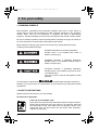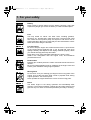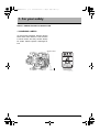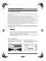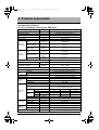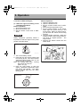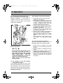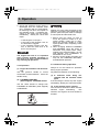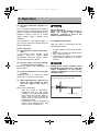
1
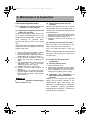
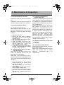
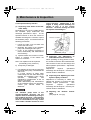
GM OPERATION.book 1 ページ 2004年10月4日 月曜日 午前11時11分 MARINE DIESEL ENGINE MODEL :ޓ1GM10(C) EPA Certified Engine It meets the low emission standards set by the EPA OPERATION MANUAL California Proposition 65 Warning Diesel engine exhaust and some of its constituents are recognized by the State of California to cause cancer, birth defects, and other reproductive harm. 002522-00E GM OPERATION.book 2 ページ 2004年10月4日 月曜日 午前11時11分 Contents CONTENTS INTRODUCTION ................................................. 3 1. FOR YOUR SAFETY ...................................... 4 1.1 WARNING SYMBOLS ............................. 4 1.2 SAFETY PRECAUTIONS ........................ 4 1.3 WARNING LABELS ................................. 7 2. PRODUCT EXPLANATION ............................ 8 2.1 USE, DRIVING SYSTEM, ETC. .............. 8 2.2 Engine Specifications .............................. 9 2.2.1 Direct Seawater Cooling Type, GM series ...................................... 9 2.2.2 Direct Seawater Cooling Type, GMC series ................................. 10 2.2.3 Direct Seawater Cooling Type, GMV series ................................. 11 2.3 Names of Parts ...................................... 12 2.4 Major Servicing Parts ............................. 13 2.5 Control Equipment ................................. 14 2.5.1 Control Panel .............................. 14 2.5.2 Single Lever Remote Control Handle (Morse Type) - Optional. ............. 16 2.5.3 Stopping Equipment.................... 16 2.5.4 Decompression Equipment ........ 16 3. OPERATION ................................................. 17 3.1 Fuel Oil, and Lube Oil ............................ 17 3.1.1 Fuel Oil........................................ 17 3.1.2 Lube Oil....................................... 18 3.2 Before Initial Operation .......................... 19 3.2.1 Supply Fuel Oil............................ 19 3.2.2 Supply Engine Lube Oil............... 19 3.2.3 Supply Clutch Lube Oil................ 19 3.2.4 Cranking...................................... 20 3.2.5 Check and Resupply Lube Oil..... 20 3.3 Operating your engine ........................... 21 3.3.1 Inspection Before Starting........... 21 3.3.2 How to Start the Engine .............. 22 3.3.3 Operation .................................... 24 3.3.4 Cautions During Operation.......... 24 3.3.5 Stopping the Engine.................... 25 3.4 Long Term Storage ................................ 26 2 4. MAINTENANCE & INSPECTION ..................27 4.1 General Inspection Rules .......................27 4.2 List of Periodic Inspection Items .............28 4.3 Periodic Inspection Items .......................30 4.3.1 Inspection on Initial 50 Hrs. of Operation (or after 1 Month) .................. 30 4.3.2 Inspection Every 50 Hours (or Monthly) .................................. 30 4.3.3 Inspection Every 150 hours. ........ 32 4.3.4 Inspection Every 300 Hrs............. 32 4.3.5 Inspection Every 600 Hrs............. 33 4.4 EPA Requirements .................................34 4.4.1 EPA and ARB Certification Plate . 34 4.4.2 Conditions to Insure Compliance with Emission Standards ..................... 35 4.4.3 Inspection and Maintenance ........ 36 4.4.4 Emission System Warranty Statement..................................... 36 5. TROUBLE AND TROUBLESHOOTING ........37 6. PIPING DIAGRAMS ......................................40 7. WIRING DIAGRAMS .....................................41 7.1 For the A-type instrument panel .............41 7.2 For the B-type instrument panel .............42 GM OPERATION.book 3 ページ 2004年10月4日 月曜日 午前11時11分 Introduction Tank you for purchasing a YANMAR Marine Diesel Engine. This Operation Manual describes the operation, maintenance and inspection of the 1GM10(C) Yanmar Marine Diesel Engines. Read this Operation Manual carefully before operating the engine to ensure that it is used correctly and that it stays in the best possible condition. Keep this Operation Manual in a convenient place for easy access. If this Operation Manual is lost or damaged, order a new one from your dealer or distributor. Make sure this manual is transfered to subsequent owners. It should be considered as a permanent part of the engine and remain so. Constant efforts are made to improve the quality and performance of Yanmar products, so some details included in this Operation Manual may differ slightly from your engine. If you have any questions about this, please contact your Yanmar dealer or distributor. The marine gear described in this manual is Yanmar Model KM Series. Operation Manual (Marine Engine) Models Code. No. 1GM10(C) 42221-556060 With regard to the sail drive, this manual describes lube oil selection and specification only. Please read the Sail Drive Operation Manual, which is supplied with the Sail Drive Unit, for further information. 3 GM OPERATION.book 4 ページ 2004年10月4日 月曜日 午前11時11分 1. For your safety 1. FOR YOUR SAFETY 1.1 WARNING SYMBOLS Most operation, maintenance and inspection problems arise due to users' failure to comply with the rules and precautions for safe operation described in this operation manual. Often, users do not understand or recognize the signs of approaching problems. Improper handling can cause burns and other injuries and can result in death. Be sure to read this operation manual carefully before operating the engine and observe all of the instructions and precautions described in this manual. Below follow the warning signs used in this manual. Pay special attention to parts containing these words and signs. 002523-00E DANGER indicates an imminently hazardous situation which, if not avoided, WILL result in death or serious injury. 002524-00E WARNING indicates a potentially hazardous situation which, if not avoided, COULD result in death or serious injury. 002525-00E CAUTION indicates a potentially hazardous situation which, if not avoided, may result in minor or moderate injury. This sign is also be used to alert against unsafe practices. The descriptions captioned by are particularly important cautions for 002526-00E handling. If you ignore them, the performance of your machine may deteriorate leading to problems. 1.2 SAFETY PRECAUTIONS (Observe these instructions for your own safety!) Precautions for Operation 002527-00E 4 Filler Cap of Fresh Water Tank Never open the cap of the fresh water tank while the engine is still hot. Steam and hot water will spurt out and burn you seriously. Wait until the temperature of the fresh water tank has dropped, wrap a cloth around the filler cap and loosen the cap slowly. After inspection, refasten the cap firmly. GM OPERATION.book 5 ページ 2004年10月4日 月曜日 午前11時11分 1. For your safety Battery Never smoke or permit sparks near the battery, because it may emit explosive hydrogen gas. Place the battery in a well-ventilated place. 002528-00E 002529-00E 002530-00E Fuel Use only diesel oil. Never use other fuels, including gasoline, kerosene, etc., because they could cause a fire. The wrong fuel could also cause the fuel injection pump and injector to fail due to lack of proper lubrication. Be sure to check that you have selected the correct diesel fuel before filling the fuel tank. Fire Prevention Be sure to stop the engine and confirm that there are no open flames in the vicinity before supplying fuel. If you do spill fuel, wipe such spillage carefully and dispose of the wiping materials properly. Wash your hands thorougly with soap and water. Never place oil or other flammable material in the engine room. Install a fire extinguisher near the engine room, and familiarize yourself with its use. Exhaust Gas Exhaust gas contains poisonous carbon monoxide and should not be inhaled. Be sure to install ventilation ports or ventilators in the engine room and ensure good ventilation during engine operation. 002531-00E Moving Parts Do not touch or let your clothing get caught in the moving parts of the engine, such as the front drive shaft, V-belt or propeller shaft, during engine operation. You will be injured. Never operate the engine without the covers on the moving parts. 002532-00E Burns The whole engine is hot during operation and immediately after stopping. The exhaust manifold, exhaust pipe and high pressure fuel pipe are very hot. Never touch these parts with your body or clothing. 002533-00E 5 GM OPERATION.book 6 ページ 2004年10月4日 月曜日 午前11時11分 1. For your safety Alcohol Never operate the engine while you are under the influence of alcohol. Never operate the engine when you are ill or feeling unwell. SAFETY PRECAUTIONS FOR INSPECTION 002534-00E Battery Fluid Battery fluid is dilute sulfuric acid. It can blind you if it gets in your eyes, or burn your skin. Keep the fluid away from your body. If you touch it, wash it off immediately with a large quantity or fresh water and call your doctor for treatment. 002535-00E Fire by Electric Short-Circuits Always turn off the battery switch before inspecting the electrical system. Failure to do so could cause short-circuiting and fires. 002536-00E Stop the engine before servicing Stop the engine before you service it. Turn the battery switch off. If you must inspect while the engine is in operation, never touch moving parts. Keep your body and clothing well clear of all moving parts. 002532-00E 002533-00E 002537-00E 002537-00E 6 Scalds If extracting oil from the engine while it is still hot, don't let the oil splash on you. Wait until the temperature has dropped before extracting cooling water from the engine. Don't let it splash on you. Forbidden Modifications Never release the limiting devices such as the engine speed limit, fuel injection limit, etc. Modification will impair the safety and performance of the product and shorten product life. Also note that any troubles arising from modification are not covered by our warranty. Precautions for Treating Waste Never dispose of waste oil or other fluid in a field, sewer, river, or the sea. Treat waste matters safely observing regulations or laws. Ask a waste recovery company to collect it. GM OPERATION.book 7 ページ 2004年10月4日 月曜日 午前11時11分 1. For your safety SAFETY PRECAUTIONS FOR INSPECTION 1.3 WARNING LABELS To insure safe operation, warning device labels have been attached. Their location is shown below and they should always be visible. Please replace if damaged or lost. Warning Label WARNING 128296-07350 1GM10 Part Code No. 128296-07350 002539-00E 7 GM OPERATION.book 8 ページ 2004年10月4日 月曜日 午前11時11分 2. Product explanation 2. PRODUCT EXPLANATION 2.1 USE, DRIVING SYSTEM, ETC. The engine is equipped with marine gear, connect the marine gear output shaft to the propeller shaft. In order to obtain full performance from your engine, it is imperative that you check the size and structure of the hull and use a propeller of the appropriate size. The engine must be installed correctly with safe cooling water and exhaust piping and electrical wiring. The PTO work should be easy to use for onboard equipment. To handle the drive equipment, driven systems (including the propeller) and other onboard equipment,be sure to observe the instructions and cautions given in the operation manuals supplied by the shipyard and equipment manufacturers. The laws of some countries may require hull and engine inspections, depending on the use, size and cruising area of the boat. The installation, fitting and surveying of this engine all require specialized knowledge and engineering skills. Consult Yanmar's local subsidiary in your region or your distributor or dealer. 002540-00E Never modify this product or release the limit devices (which limit engine speed, fuel injection quantity, etc.). Modification will impair the safety and performance of the product and functions and shorten the product life. Please note that any troubles arising from modification of the product will not be covered by our warranty. DETAIL OF NAME PLATE The name plate shown below is attached to the engine. Check the engine's model, output, rpm and serial number on the name plate. MODEL CONT. RATING MAX. OUT PUT ENGINE NO. kW kW YANMAR DIESEL ENGINE rpm rpm The name plate shown below is described in the marine gear. Check the marine gear's model, gear ratio, oil used, oil quantity and serial number. MODEL GEARRATIO OIL OIL QTY. NO. KM SAE 20 / 30 HD LTR. KANZAKI OSAKA JAPAN YANMAR CO., LTD. MADE IN JAPAN 8 002541-00E GM OPERATION.book 9 ページ 2004年10月4日 月曜日 午前11時11分 2. Product explanation 2.2 Engine Specifications 2.2.1 Direct Seawater Cooling Type, GM series Engine Model Type Combustion system Number of cylinders Bore × stroke Displacement Output/crankshaft speed Continuous rating output Brake mean effective pressure Piston speed Output/crankshaft speed One hour rating output Brake mean effective pressure Piston speed mm (in.) l (cu.in.) kW/rpm (HP/rpm) 1GM10 Vertical 4-cycle water cooled diesel engine Swirl pre-combustion chamber 1 75 × 72 (2.95 × 2.83) 0.318 (19.40) 5.9/3400 (8.02/3400) kg/cm2 (lb./in.2) m/sec. (ft./sec.) kW/rpm (HP/rpm) 6.66 (94.71) 8.16 (26.77) 6.7/3600 (9.1/3600) kg/cm2 (lb./in.2) m/sec. (ft./sec.) 7.07 (100.54) ° 15 ± 1 kg/cm2 (lb./in.2) 170 ± 5 (2347 - 2489) rpm rpm l (cu.in.) kg (lb.) mm (in.) mm (in.) mm (in.) at Flywheel side at Crankshaft V-pulley side Counter-clockwise viewed from stern Clockwise viewed from stern Direct seawater cooling (rubber impeller water pump) Complete enclosed forced lubrication Electric and manual DC 12V, 1.0kW 12V, 35A KM2P Mechanical cone clutch with single stage for both ahead and astern 2.21 2.62 3.22 3.06 3.06 3.06 1540 1298 1055 1113 1113 1113 0.3 (18.31) 10.3 (22.71) 554 (21.81) 410 (16.14) 485 (19.09) l (cu.in.) 1.3 (79.33) l (cu.in.) 0.6 (36.61) kg (lb.) 76 (167) 8.64 (28.35) 23.0 Compression ratio Fuel injection timing (b.T.D.C.) Fuel injection pressure Main power take off Front power take off Crankshaft Direction of rotation Propeller shaft (Ahead) Cooling system Lubrication system Type Starting Starting motor system AC generator Model Type Marine gear system Dimensions Forward Reverse Forward Propeller speed Reverse Lubricating oil capacity Weight Overall length Overall width Overall height Reduction ratio Lubricating oil Total capacity (rake angle 8°) Effective Engine weight with marine gear (Note) 1. Rating condition: ISO 3046-1 and ISO 8665. 2. 1hp=0.7355 kW. 9 GM OPERATION.book 10 ページ 2004年10月4日 月曜日 午前11時11分 2. Product explanation 2.2.2 Direct Seawater Cooling Type, GMC series Engine Model Type Combustion system Number of cylinders Bore × stroke Displacement Output/crankshaft speed Continuous rating output Brake mean effective pressure Piston speed Output/crankshaft speed One hour rating output Brake mean effective pressure Piston speed mm (in.) l (cu.in.) kW/rpm (HP/rpm) 1GM10C Vertical 4-cycle water cooled diesel engine Swirl pre-combustion chamber 1 75 × 72 (2.95 × 2.83) 0.318 (19.40) 5.9/3400 (8.02/3400) kg/cm2 (lb./in.2) m/sec. (ft./sec.) kW/rpm (HP/rpm) 6.66 (94.71) 8.16 (26.77) 6.7/3600 (9.1/2600) kg/cm2 (lb./in.2) m/sec. (ft./sec.) 7.07 (100.54) ° 15 ± 1 kg/cm2 (lb./in.2) 170 ± 5 (2347 - 2489) rpm rpm mm (in.) mm (in.) mm (in.) at Flywheel side at Crankshaft V-pulley side Counter-clockwise viewed from stern Clockwise viewed from stern Direct seawater cooling (rubber impeller water pump) Complete enclosed forced lubrication Electric and manual DC 12V, 1.0kW 12V, 35A SD20 Sail drive unit- Dog type clutch, spiral bevel gear type 2.64 2.64 1290 1290 412 (16.22) 410 (16.14) 485 (19.09) l (cu.in.) 1.3 (79.33) l (cu.in.) 0.6 (36.61) kg (lb.) 104 (229) 8.64 (28.35) 23.0 Compression ratio Fuel injection timing (b.T.D.C.) Fuel injection pressure Main power take off Front power take off Crankshaft Direction of rotation Propeller shaft (Ahead) Cooling system Lubrication system Type Starting Starting motor system AC generator Model Type Forward Marine gear Reduction system ratio Reverse Forward Propeller speed Reverse Overall length Dimensions Overall width Overall height Lubricating oil Total capacity (rake angle 8°) Effective Engine weight with sail driver (Note) 1. Rating condition: ISO 3046-1 and ISO 8665. 2. 1hp=0.7355 kW. (Note) Sail drive unit will be coupled with the engine in the market. 10 GM OPERATION.book 11 ページ 2004年10月4日 月曜日 午前11時11分 2. Product explanation 2.2.3 Direct Seawater Cooling Type, GMV series Engine Model Type Combustion system Number of cylinders Bore × stroke Displacement Output/crankshaft speed Continuous Brake mean rating output effective pressure (DIN 6270A) Piston speed Output/crankshaft speed One hour rating output (DIN 6270B) Brake mean effective pressure Piston speed mm (in.) l (cu.in.) kW/rpm (HP/rpm) 1GM10V Vertical 4-cycle water cooled diesel engine Swirl pre-combustion chamber 1 75 × 72 (2.95 × 2.83) 0.318 (19.40) 5.9/3400 (8.02/3400) kg/cm2 (lb./in.2) m/sec. (ft./sec.) kW/rpm (HP/rpm) 6.66 (94.71) 8.16 (26.77) 6.7/3600 (9.1/3600) kg/cm2 (lb./in.2) m/sec. (ft./sec.) 7.07 (100.54) ° 15 ± 1 kg/cm2 170 ± 5 (2347 - 2489) 8.64 (28.35) 23.0 Compression ratio Fuel injection timing (b.T.D.C.) Fuel injection pressure (lb./in.2) Main power take off Front power take off Crankshaft Direction of rotation Propeller shaft (Ahead) Cooling system Lubrication system Type Starting Starting motor system AC generator Model at Flywheel side at Crankshaft V-pulley side Clockwise viewed from stern Clockwise viewed from stern Direct seawater cooling (rubber impeller water pump) Complete enclosed forced lubrication Electric and manual DC 12V, 1.0kW 12V, 35A KM3V V-drive, mechanical cone clutch with single stage for both ahead and astern (Angle 15 degree) 2.36 3.16 Type Marine gear system Dimensions Reduction ratio Forward Reverse Propeller Forward speed DIN 6270A rating Reverse rpm 1076 Lubricating oil capacity Weight Overall length Overall width Overall height l (cu.in.) kg (lb.) mm (in.) mm (in.) mm (in.) 0.8 (48.92) 19.5 (43.0) 680 (26.77) 450 (17.71) 554 (21.81) l (cu.in.) 1.3 (79.33) l (cu.in.) 0.6 (36.61) kg (lb.) 90 (198) Lubricating oil Total capacity (rake angle 8°) Effective Engine weight with marine gear rpm 1441 (Note) 1. Rating condition: ISO 3046-1 and ISO 8665. 2. 1hp=0.7355 kW. 11 GM OPERATION.book 12 ページ 2004年10月4日 月曜日 午前11時11分 2. Product explanation 2.3 Names of Parts Non Operation Side Decompression lever Fuel injection valve Intake silencer Tachometer sensor Dipstick Alternator Marine gearbox Starter motor Output shaft coupling Shift lever 1GM10 with KM2P Operation Side Name plate Thermostat cover Fuel injection pump Fuel oil filter Mixing elbow Idle adjuster Oil filler cap Fuel injection limiter Engine stop lever Mounting flange Crankshaft V-pulley Dipstick Cooling seawater pump Fuel feed pump Regulator handle 12 Lubricating oil filter 002542-00E GM OPERATION.book 13 ページ 2004年10月4日 月曜日 午前11時11分 2. Product explanation 2.4 Major Servicing Parts Name of part Function Decompression lever Opens the exhaust valve and releases the pressure for manual starting. Fuel filter Removes dust and water from fuel. Drain the filter periodically. The internal element (filter) should be changed periodically. Fuel feed pump, Priming lever Feed fuel to the fuel injection pump. Moving the priming lever up and down feeds the fuel. When there is no fuel, the priming lever is used to bleed air from the fuel system. Filler port (engine) Filler port for engine lube oil. Filler port (marine gear) Filler port for marine gear lube oil. Lube oil filter Filters fine metal fragments and carbon from the lube oil. Filtered lube oil is distributed to the engine’s moving parts. Cooling Water System Direct seawater cooling. Seawater cooling The seawater pump feeds seawater. The flow is controlled automatically by a thermostat which measures the temperature during operation. Anticorrosion zinc The metal area of the seawater cooling system is prone to electrical corrosion. The anticorrosion zinc is installed in the cylinder block and/or cylinder head to prevent this. The anticorrosion zinc is itself reduced over time by electrical corrosion, so it must be replaced at fixed intervals before it is completely consumed in order to ensure that the metal area of the seawater cooling system remains fully protected. Intake air silencer This is the air intake silencer. The silencer guards against dirt in the air and reduces the noise of air intake. Name plate Name plates are provided on the engine and the marine gear and have the model, serial number and other data. Starter Starter motor for the engine. Powered by the battery. Alternator Rotates by belt drive, generates electricity and charges the battery. 13 GM OPERATION.book 14 ページ 2004年10月4日 月曜日 午前11時11分 2. Product explanation 2.5 Control Equipment The equipment in the control room, making remote control possible, consists of: the instrument panel, which is connected by wire harness; the remote control handle, which is hooked up by remote control cable to each of the engine control levers, and the stopping equipment. 2.5.1 Control Panel Electric Operation There are two control panel options. The controls and alarm lamps included are shown below. (A) ԘWater Proof (sail drive) ԙHigh temp. cooling water ԚLow lube oil pressure 14 (B) ԛCharge ԜKey switch ԝBuzzer ԞStart switch ԟTachometre ԠIllumination switch 002543-00E GM OPERATION.book 15 ページ 2004年10月4日 月曜日 午前11時11分 2. Product explanation (1) Controls and Equipment Note: The mark B indicates equipment for type B control panel only. Controls and Equipment OFF ON Mechanism Key Switch Rotary switch with 2 positions. In the OFF position, the switch key can be inserted or removed. In OFF, all electric current is cut off. In ON (1 position to the right), the engine is turned on. In ON, electric current to the controls and equipment is turned on. The engine cannot be stopped with the key switch. 002546-00E Alarm Lamps Lamps come on when there is a problem. See Section 2 for the types of lamps and the way they work. Alarm Buzzer Buzzer goes off when there is a problem. B Illumination Switch B Tachometre B Hour Metre (optional) The switch turns on the control panel lamps. The engine’s rotation speed is indicated by the needle. The number of hours of operation is indicated, and can be used as a guide for periodic maintenance checks. The hour meter is at the bottom of the tachometre. (2) Alarm Equipment (lamps and buzzer) Mechanism When the sensor detects a problem during operation, the lamps come on and the buzzer goes off. Control Panel (TypeA) There are 4 separate alarm monitors on the upper left side of the control panel. Control Panel (TypeB) Alarm monitors are located on the upper right side of the control panel. Under normal conditions, the monitors are off. When there is a problem, the monitors light up. (3) Alarm Devices Check that the pilot lamps on the instrument panel are as shown below when the starter key is turned on: Low L.O. pressure alarm lamp Lit Pilot Lit lamps Charge lamp Cooling water temp. alarm lamp Off NOTE: All these signals will continue until the engine starts up or the key is turned off. 15 GM OPERATION.book 16 ページ 2004年10月4日 月曜日 午前11時11分 2. Product explanation 2.5.2 Single Lever Remote Control Handle (Morse Type) - Optional. This remote control system uses a single handle to operate marinegear-clutch(neutral, forward, reverse) and to control the engine speed. injection pump stop lever thus cutting off fuel injection. Engine stopping by engine stop cable NEUTRAL: Power to the propeller shaft is cut off and the engine idles. FWD (FORWARD) REV (REVERSE) Engine stop cable 002548-00E 2.5.4 Decompression Equipment Ԙ FWD(forward) ԙ REV(reverse) Ԛ NEUTRAL(boat is stopped) ԛ Clutch is disengaged Ԝ Pull out handle The decompression lever is used for manual starting. When the decompression lever is pulled, the exhaust valve opens causing decompression inside the cylinders and making hand-turning possible. Returning the lever to the original position closes the exhaust valve, allowing compression and operation condition. 002547-00E The handle controls the course of the boat (ahead or astern) and, at the same time, acts as an accelerator increasing the engine speed as it is pushed further in the FWD or REV direction. If the handle is pulled out, engine speed can be controlled without engaging the clutch (clutch remains in the NEUTRAL, no load position). 2.5.3 Stopping Equipment Manual Operation The engine is stopped by pulling out the engine stop knob, which catches the fuel 16 Decompression Decomp. lever Drive 002549-00E GM OPERATION.book 17 ページ 2004年10月4日 月曜日 午前11時11分 3. Operation 3. OPERATION 3.1 Fuel Oil, and Lube Oil 3.1.1 Fuel Oil 002550-00E When other than the specified fuel oil is used, the engine will not perform to full capacity and parts may be damaged. (3) Fuel Tank (optional) Be sure to attach a drain cock to the fuel tank to enable dirt and water to settle at the bottom of the tank to be drained off. The fuel outlet should be positioned 2030mm above the bottom of the tank so that only clean fuel is used. (1) Selection of Fuel Oil Use diesel fuels for best engine performance. Cetane fuel number should be 45 or greater. (2) Handling of Fuel Oil 1)Water and dust in the fuel cause engine failure. When fuel is stored, be sure that the inside of the storage con- 2)Keep the fuel container stationery for several hours to allow any dirt or water to settle to the bottom. Use a pump to extract the clear, filtered fuel from the top of the container for use. ԙ Ԛ tainer is clean, and that the fuel is stored away from dirt or rain water. Ԙ ԛ Ԙ Sediment ԙԚ Drain cock ԛ To engine 002552-00E (4) Fuel System Install the fuel pipe from the fuel tank to the fuel pump in accordance with the diagram. The oil/water separator (optional) is placed at the centre section of the line. 1 8 Fuel system 2 3 9 10 5 7 Use the clear filtered fuel from the upper middle section of the container only, leaving any 002551-00E contaminated fuel at the bottom. 4 6 Ԙ Fuel filter ԙ Fuel feed pump (priming lever) Ԛ Oil/Water separator ԛ Approx. 25 mm Ԝ Within 500 mm ԝ Drain cock Ԟ Fuel cock ԟ Fuel returm Ԡ To fuel injection pump ԡ Fuel tank 002553-00E 17 GM OPERATION.book 18 ページ 2004年10月4日 月曜日 午前11時11分 3. Operation 3.1.2 Lube Oil Air temperature Single grade Multi grade (3) The Sail Drive attached to • SAE Viscosity.....................30 (4) Handling the Lube Oil 1)When handling and storing lube oil, be careful not to allow dust and water to enter the lube oil. Clean around the filter port before refilling. 2)Do not mix lube oils of different types or brands. Mixing may cause the chemical characteristics of the lube oil to change and lubricating performance to drop, reducing the engine’s life. Before supplying lube oil to the engine and marine gear for the first time, extract all the lube oil already in the tank. Use new lube oil. 3)Lube oil supplied to the engine will undergo natural degeneration with time even when the engine is not used. Lube oil should be replaced at the specified intervals, regardless of whether the engine is being used or not. 18 104q 30q 86q 20q 68q 10q 50q 0q 32q -5q -10q 23q 14q -15q -20q -25q -30q -35q -40q 5q -4q -13q -22q -31q -40q -56q -67q SAE 10W20 40q SAE 20W40 122q SAE 15W40 SAE 15W30 SAE 10W 50q SAE SW20 (2) Selection of Oil for Marine Gear • SAE Viscosity.....................30 SAE 30 (1) Selection of Engine Lube Oil Use the following lube oil: • API Classification ...............CD • SAE Viscosity.....................15W40 SAE 40 002550-00E Using other than the specified lube oil will lead to seizure of parts, abnormal wear, andshorten engine life. If you operate your equipment at temperatures below the limits shown, consult four dealer for special lubricants and starting aids. 002554-00E GM OPERATION.book 19 ページ 2004年10月4日 月曜日 午前11時11分 3. Operation 3.2 Before Initial Operation Perform the following before using the engine for the first time: 3.2.1 Supply Fuel Oil Using gasoline, etc. may cause a fire. To avoid mistakes, be sure to double-check the kind of fuel before inserting. Wipe off any spilled fuel carefully. 002529-00E 1. Before filling with fuel, wash out the fuel tank and fuel system with clean kerosene or light oil. 2. Fill the tank with clean fuel oil free of dirt and water. 3.2.2 Supply Engine Lube Oil 1. Remove the filler port cap (yellow), and fill with engine oil. 2. Fill with oil to the upper limit on the dipstick. Insert the dipstick fully to check the level. (Check the level without screwing the dipstick in.) 3. Tighten the filler port cap securely by hand. ԙ Ԙ Ԛ ԛ ԘFiller portޓޓޓޓޓԚUpper limit ԙDipstick ޓ ޓޓޓޓԛLower Limit 002555-00E 3.2.3 Supply Clutch Lube Oil 1. Remove the filler port cap at the top of the marine gear, and fill with marine gear- clutch- lube oil. 2. Fill with oil to the upper limit on the dipstick. insert the dipstick fully to check the level. 3. Tighten the filler port cap securely by hand. Marine gear oil capacity KM2P 0.3l Engine Oil Capacity (Oil Pan) 1GM10(V)(C) Ԙ Full:1.5l/Effective:0.8l 002550-00E ԙ Ԛ Overfilling will cause oil to be sprayed out from breather and lead to engine problems. ԘOil filler port cap ԙUpper limit/Lower limit ԚDipstick 002556-00E 19 GM OPERATION.book 20 ページ 2004年10月4日 月曜日 午前11時11分 3. Operation 3.2.4 Cranking When the engine has not been used for a long period of time, lube oil will not be distributed to all of the operating parts. Using the engine in this condition will lead to seizure. After a long period of disuse, distribute lube oil to each part by cranking. Perform in accordance with the following procedures before beginning operation. 1. Open Kingston cock. 2. Open fuel tank cock. 3. Put remote control lever in NEUTRAL. Manual start position ԙ Ԙ Ԙ Forward Ԛ ԙ Neutral 002558-00E Ԛ Reverse 002557-00E Manual Operation 4. Pull out decompression lever. 5. Put starting handle on the starting shaft, and turn about 10 times. Check for abnormal noise while cranking. Decompression Decomp. lever Drive 002549-00E 20 Electric Operation 4. Turn on battery switch and insert key into key switch. Turn the key to the ON position. 5. Pul the stop knob continuously while cranking. 6. When the start button is pushed, the engine will begin cranking. Continue cranking for about 5 seconds, and check for abnormal noise during that time. (If you remove your hand from the stop knob while cranking, the engine will start. Pull continuously.) 3.2.5 Check and Resupply Lube Oil When engine oil or clutch oil is supplied for the first time or when they must be replaced, conduct a trial operation of the engine for about 5 minutes and check the quantity of lube oil. The trial engine operation will send the lube oil to the parts, so the lube oil level will drop. Check and resupply as necessary. 1. Supplying engine lube oil (See 3.2.2) 2. Supplying marine gear lube oil (See 3.2.3) GM OPERATION.book 21 ページ 2004年10月4日 月曜日 午前11時11分 3. Operation 3.3 Operating your engine 002540-00E To prevent exhaust gas poisoning, ensure good ventilation during operation. Install ventilation windows, ports or ventilators in the engine room. Never touch or allow your clothes to touch the moving parts of the engine during operation. If the front drive shaft, V-belt, propeller shaft, etc. catches your body or clothes, serious injury may result. Check that no tools, cloth, etc. are left on or around the engine. 002696-00E The engine is very hot during operation and immediately after stopping, especially the exhaust pipe. Avoid burns! Never touch or allow your clothes to touch any part of the engine. 3.3.1 Inspection Before Starting Before starting the engine, make it a daily rule to conduct the following inspections: (1) Visual Checks Check for the following: 1. Lube oil leakage from the engine 2. Fuel oil leakage from the fuel system 3. Water leakage from the cooling water system 4. Damage to parts 5. Loosening or loss of bolts If any problem is found, do not operate the engine before completing repairs. (3) Checking and Resupplying Engine Lube Oil 1. Check the engine oil level with the oil dipstick. 2. If the oil level is low, supply with the recommended lube oil using the filler port. Supply oil up to the top mark on the oil dipstick. (See 3.2.2) (4) Checking and Resupplying Clutch Lube Oil 1. Check the clutch oil level with the oil dipstick. 2. If the oil level is low, supply with the recommended lube oil using the filler port. Supply oil up to the top mark on the oil dipstick. (See 3.2.3) (5) Checking the Remote Control Handle Be sure to check that the remote control handle lever moves smoothly before use. If it is hard to operate, lubricate the joints of the remote control cable and also the lever bearings. If the lever comes out or there is play in the lever, adjust the remote control cable. (See 4.3.4(3)) (6) Checking the Alarm Devices Electric Operation When operating the key switch, check that the alarm devices work normally. (See 2.5.1(3)) (7) Preparing Fuel, and Lube Oil in Reserve Prepare sufficient fuel for the day’s operation. Always store lube oil in reserve (for at least one refill) onboard, to be ready for emergencies. (2) Checking and Resupplying Fuel Oil Check the fuel level inside the fuel tank and supply with the recommended fuel, if necessary. (See 3.2.1) 21 GM OPERATION.book 22 ページ 2004年10月4日 月曜日 午前11時11分 3. Operation 3.3.2 How to Start the Engine (1) Start the engine according to the following procedures: Electric Operation 1. Open the Kingston cock. 2. Open the fuel tank cock. 3. Set the remote control lever in NEUTRAL. 002550-00E Safety equipment (optional) makes it impossible to start the engine in any other position than NEUTRAL. Manual Operation 1. Open the Kingston cock. 2. Open the fuel tank cock. 3. Set the remote control lever in NEUTRAL. 4. Pull out the decompression lever. 5. Put the starter handle on the starter shaft, align the groove and pin, and turn by hand. When you begin turning, you will hear the sound of fuel being injected. 6. Turn the handle vigorously. When the rotation is rapid, return the decompression lever to original position. The engine starts. 7. Remove the starter handle from the starter shaft. Decompression Decomp. lever Drive 002559-00E 4. Turn on the battery switch. 5. Insert the key into the key switch and turn the key to ON. If the alarm buzzer sounds and alarm lamps come on, the alarm devices are normal. Note: The cooling water temp. warning lamp does not come on. (See 2.5.1.(3)) 6. Push the start button to start the engine. Release the start button when the engine has started. The alarm buzzer should stop and the alarm lamps go out. Ԙ OFF position ԙ ON position Ԙ ԙ OFF ON 002560-00E 22 002549-00E GM OPERATION.book 23 ページ 2004年10月4日 月曜日 午前11時11分 3. Operation (2) Restarting After Starting Failure Before pushing the start button again, be stopped completely. If the engine is restarted while the engine still has not stopped, the pinion gear of the starter motor will be damaged. Manual start position Fuel System Air Venting Procedures 1. Check the fuel level in the fuel tank. Replenish if insufficient. 2. Loosen the air vent bolt at the top of the oil/water separator by turning it 2 or 3 times. When fuel which does not contain air bubbles comes out of the bolt hole, tighten the air vent bolt. 3. Loosen the air vent bolts of the fuel filter and the fuel injection pump by turning them 2 or 3 times. 4. Feed fuel with the fuel feed pump by moving the lever on the left side of the feed pump up and down. 5. Allow the fuel containing air bubbles to flow out from the air vent bolt holes. When the fuel coming out no longer contains bubbles, tighten the air vent bolts. This completes the air venting of the fuel system. Try starting the engine again. (4) After the Engine has Started After the engine has started, check the following items at a low engine speed: 002558-00E Electric Operation 002550-00E Do not hold the start button on for more than 15 seconds at a time. If the engine does not start the first time, wait for about 15 seconds before trying again. After the engine has started, do not turn the key off. (It should remain ON.) Alarm devices will not work when the key is OFF. 1. Check that the gauges and alarm devices on the instrument panel are normal. 2. Check for water or oil leakage from the engine. 3. Check that exhaust colour, engine vibrations and sound are normal. 4. When there are no problems, keep the engine at low speed with the boat still stopped to send lube oil to all parts of the engine. (3) Air Venting of the Fuel System After Starting Failure If the engine only idles and won’t start after several attempts, there may be air in the fuel system. If air is in the fuel system, fuel cannot reach the fuel injection pump. Vent the air in the system according to the following procedures. 23 GM OPERATION.book 24 ページ 2004年10月4日 月曜日 午前11時11分 3. Operation 5. Check that sufficient cooling water is discharged from the seawater outlet pipe. Operation with too small seawater discharge will burn the impeller of the seawater pump. If seawater discharge is too small, stop the engine immediately. Identify the cause and repair. • Is the Kingston cock open? • Is the inlet of the Kingston cock on the full bottom clogged? • Is the seawater suction hose broken, or does the hose suck in air due to a loose joint? 002550-00E The engine will seize if it is operated when cooling seawater discharge is too small or if load is applied without any warming up operation. Shifting the clutch while operating at high speed or not pushing the handle fully into position (half clutch) will result in damage to clutch parts and abnormal wear. 1. Before using the clutch, be sure to move the governor handle to a low speed position (1000 rpm or less). Move the governor handle to a high speed position after completing clutch operation. 2. When changing between FORWARD and REVERSE, bring the clutch to NEUTRAL and pause before slowly shifting to the desired position. Do not shift abruptly from FORWARD to REVERSE or vice versa. 3. Move the clutch handle accurately and fully into the FORWARD, NEUTRAL, and REVERSE positions. 3.3.4 Cautions During Operation 3.3.3 Operation (1) Engine Acceleration and Deceleration Use the governor handle to control acceleration and deceleration. Move the handle slowly. (2) FORWARD-NEUTRAL (boat stopped) - REVERSE Clutch Use the clutch handle to change from FORWARD to NEUTRAL (boat stopped) to REVERSE. 002559-00E 24 002550-00E Always be on the lookout for problems during engine operation. Pay particular attention to the following: (1) Is sufficient water being discharged from the seawater outlet pipe? If the discharge is small, stop the engine immediately, identify the cause and repair. (2) Is the exhaust colour normal? The continuous emission of black exhaust indicates engine overloading. This shortens the engine’s life and should be avoided. GM OPERATION.book 25 ページ 2004年10月4日 月曜日 午前11時11分 3. Operation (3) Are there abnormal vibrations or noise? Do not operate at speeds which produce violent vibrations. Depending on the hull structure, engine and hull resonance may suddenly become great at a certain engine speed range, causing heavy vibrations. Avoid operation in this speed range. If you hear any abnormal sounds, stop the engine and inspect. Electric Operation (4) Alarm buzzer sounds during operation. If the alarm buzzer sounds during operation, lower the engine speed immediately, check the warning lamps, and stop the engine for repairs. (5) Is there water, oil, or gas leakage, or are there any loose bolts? Check the engine room periodically for any problems. (6) Is there sufficient fuel oil in the fuel oil tantk? Replenish fuel oil in advance to avoid running out of fuel during operation. 002550-00E Electric Operation Never turn off the battery switch or spark the battery cable during operation. Damage to parts in the electric system will result. 3.3.5 Stopping the Engine Stop the engine in accordance with the following procedures: 1. Put the remote control handle in NEUTRAL. 2. Be sure to race the engine before stopping it. (See 3.3.4(7)) 3. Cool down the engine at low speed (approximately 1000 rpm) for about 5 minutes. 002550-00E Stopping the engine suddenly while operating at high speed will cause the engine temperature to rise quickly, causing deterioration of the oil and sticking of parts. Engine stopping by engine stop cable (7) When operating the engine at low speed for long periods of time, race the engine once every 2 hours. Note: Racing the Engine With the clutch in NEUTRAL, accelerate from the low speed position to the high speed position and repeat this process about 5 times. This is done to clean out carbon from the cylinders and the fuel injection valve. Neglecting to race the engine will result in poor exhaust colour and reduce engine performance. Engine stop cable 002548-00E 25 GM OPERATION.book 26 ページ 2004年10月4日 月曜日 午前11時11分 3. Operation 4. Continue to pull out the engine stop knob (stop lever) until the engine is completely stopped. If you release the knob before the engine has completely stopped, it may restart. 5. Close the fuel tank cock. 6. Close the sea cock. 002550-00E Neglecting to close the Kingston cock will allow water to leak into the boat and may cause it to sink. Be sure to close the cock. Note: The engine may be stopped by pulling out the decompression lever, but avoid doing so except in times of emergency. In this case, the engine is stopped by cutting off the air pressure. However, fuel injection does not stop, and fuel is leftover in the combustion chamber. This will lead to abnormal combustion when the engine is restarted and is not desirable. 3.4 Long Term Storage In cold temperatures or before long term storage, be sure to drain the water from the seawater cooling system. 002696-00E Drain water from the cooling system after the engine has cooled down. Be careful to avoid burns. 002550-00E If water is left inside, it may freeze and damage parts of the cooling system cylinder block, seawater pump, etc.) Outlet Cam Inlet Seawater pump body Impeller Packing Side cover 002561-00E 1. Loosen the drain cock at the side of the thermostat cover, and drain off the water inside. 2. Loosen the 3 bolts fixing the side cover of the seawater pump, remove the cover and drain the water from inside. Retighten the bolts when finished. 3. Close the drain cock. 26 GM OPERATION.book 27 ページ 2004年10月4日 月曜日 午前11時11分 4. Maintenance & Inspection 4. MAINTENANCE & INSPECTION 4.1 General Inspection Rules Conduct Periodic Inspection for Your Safety. The functions of engine components will degenerate and engine performance will drop according to the use of the engine. If countermeasures are not taken, you may encounter unexpected troubles while cruising at sea. Consumption of fuel or lube oil may become excessive and exhaust gas and engine noise may increase. These all shorten the life of the engine. Daily and periodic inspection and servicing increase your safety at sea. Inspect Before Starting. Make it a daily rule to inspect before starting. (See 3.3.1) Periodic Inspections at Fixed Intervals. Periodic inspections must be made after every 50, 150, 300 and 600 hours of use. Conduct periodic inspections according to the procedures described in this Operation Manual. Use Genuine Parts. Be sure to use genuine parts for consumable and replacement parts. Use of other parts will reduce engine performance and shorten the life of the engine. Consult Your YANMAR Dealer or Distributor. Specialized technicians are ready to assist you with periodic inspections and maintenance. Consult your YANMAR dealer or distributor in accordance with the service agreement. Servicing Tools Prepare servicing tools onboard to be ready for inspecting and servicing the engine and other equipment. Tightening Torque of Bolts & Nuts Over-tightening of bolts and nuts causes them to come off or their threads to be damaged. Insufficient tightening causes oil leakage from the installation face or troubles due to the loosening of bolts. Bolts and nuts must be tightened to the appropriate tightening torque. Important parts must be tightened with a torque wrench to the correct tightening torque and in the right order. Consult with your dealer or distributor if the servicing requires the removal of such parts. The standard tightening torque standard bolts & nuts is listed below. for 002550-00E Apply the following tightening torque to bolts having “7“ on the head. (JIS strength classification: 7T) Tighten bolts with no “7“ mark to 60% tightening torque. If the parts to be tightened are made from light alloy aluminum, tighten the bolts to 80% tightening torque. Bolt dia. × pitch mm Tightening torque Nm M6×1.0 M8×1.25 11±01 26±03 M10×1.5 M12×1.75 M14×1.5 50±05 90±10 140±15 M16×1.5 230±20 27 GM OPERATION.book 28 ページ 2004年10月4日 月曜日 午前11時11分 4. Maintenance & Inspection 4.2 List of Periodic Inspection Items Daily and periodic inspections are important to keep the engine in its best condition. The following is a summary of inspection and servicing items by inspection interval. Periodic inspection intervals should vary depending on the uses, loads, fuels and lube oils used and handling conditions, and are hard to establish definitively. The following should be treated as a general standard only. Section 4.3 gives a detailed explanation of which parts must be inspected and the procedure for doing so for each interval. 28 002550-00E Schedule your own periodic inspection plan according to the operational conditions of your engine and inspect every item. Neglect of periodic inspection may head to engine troubles and shorten the life of the engine. Inspection and servicing at 600 hours and thereafter require special knowledge and techniques. Consult your Yanmar dealer or distributor. GM OPERATION.book 29 ページ 2004年10月4日 月曜日 午前11時11分 4. Maintenance & Inspection : Check System Before starting Item 0:Replace After50 hrs or one month Every 150 hrs :Consult local dealer Every 300hrs Every 600 hrs (1 year) Check the fuel level, and refill Drain the fuel tank Fuel system* (first) Drain the fuel filter Replace the fuel filter 0 Check the injection timing Check the injection spray condition Check the lube oil level Lubricating system Replace the lube oil Crankcase Marine gear Crankcase 0(first) 0 Marine gear 0(first) 0 Check the oil pressure warning lamp function Replace the lube oil filter Seawater outlet Cooling system 0(first) 0 During operation Check the impeller of the cooling water pump (seawater pump) Check and replace the anticorrosion zinc 0 Adjust the tension of the seawater pump driving blet (first) Clean the element of the air intake silencer Clean the exhaust/water mixing elbow Air intake and exhaust system Clean the breather pipe Check the exhaust gas condition During operation Check the charge lamp function Electrical system Check the electrolyte level in the battery Adjust the tension of the alternator driving belt (first) Check the wiring connectors Check for leakage of water and oil Cylinder head, etc. Retighten all major nuts and bolts Adjust intake/exhaust valve clearance Remote control system, etc. (After starting) (first) Check the remote control operation (first) Adjust the propeller shaft alignment (first) *For EPA Requirements, see also 4.4 29 GM OPERATION.book 30 ページ 2004年10月4日 月曜日 午前11時11分 4. Maintenance & Inspection 4.3 Periodic Inspection Items 4.3.1 Inspection on Initial 50 Hrs. of Operation (or after 1 Month) (1) Replacing the Engine Lube Oil and Lube Filter (1st time) During initial operation of the engine, the oil is quickly contaminated due to the initial wear of internal parts. The lube oil must therefore be replaced early. Replace the lube oil filter at the same time. It is easiest and most effective to drain the engine lube oil after operation while the engine is still warm. 1. Remove the lube oil dipstick. Attach the oil drain pump and drain off oil. 2. Remove the lube oil filter with the filter detach/attach tool. (Turn to the left.) 3. Clean the filter installation face and attach the new filter, tightening by hand. 4. Turn an additional 3/4 of a turn with the attachment tool. (Turn to the right. Tightening torque: 20∼24 Nm) 5. Fill with new lube oil. (See 3.2.2) 6. Perform a trial run and check for oil leakage. 7. Approximately 10 minutes after stopping the engine, remove the oil dipstick and check the oil level. Add oil if the level is too low. 002696-00E Beware of oil splashes if extracting the lube oil while it is hot. 30 (2) Replacing the Clutch Lube Oil (1st time) During initial operation, the oil is quickly contaminated due to the initial wear of internal parts. The lube oil must therefore be replaced early. 1. Remove the cap from the filler port and attach the oil drain pump. Drain off oil. 2. Fill with new lube oil. (See 3.2.3) 3. Perform a trial run and check for oil leakage. (3) Draining the (optional) Fuel Tank Open the drain cock and drain off any water or dirt collected on the bottom. Put a pan under the drain to catch the fuel. Once the water and dirt has been drained off and the fuel coming out is clear, close the drain cock. 4.3.2 Inspection Every 50 Hours (or Monthly) (1) Draining the Fuel Filter 1. Close the fuel oil cock. 2. Remove the fuel filter cover and drain off any water and dirt collected inside. 3. After reassembly, be sure to vent air from the fuel system. (See 3.3.2(3)) (2) Inspection and adjustment of Intake/Exhaust Valve Clearance (1st time) Setting of a new engine and individual engine use will cause changes in the intake/exhaust valve and rocker arm clearance, and adjustment is necessary. This adjustment requires specialized knowledge and techniques. Consult your Yanmar dealer or distributor. GM OPERATION.book 31 ページ 2004年10月4日 月曜日 午前11時11分 4. Maintenance & Inspection (3) Adjusting the Remote Control Cable The various control levers on the engine side are connected to the remote control lever by the remote control cable. The cable will become stretched and the attachments loose after long hours of use causing deviation. It is dangerous to control operation under these conditions, and the remote control cable must be checked and adjusted periodically. A) Adjusting the Governor Remote Control Cable Check to see that the control lever on the engine side moves to the high speed bolt position and low speed bolt position when the remote control lever is moved to H(high speed) and L(low speed) respectively. When there is deviation, loosen the bracket for the remote control cable on the engine side and adjust. Adjust the high speed bolt position first and then adjust the low speed idling. B) Adjusting the Clutch Remote Control Cable Check to see that the control lever moves to the correct position when the remote control handle is put in NEUTRAL, FORWARD, REVERSE. Use the NEUTRAL position as the standard for adjustment. When there is deviation, loosen the bracket for the remote control cable on the clutch side and adjust. (4) Electric Operation Ensure good ventilation when charging the battery. The use of open flames is strictly prohibited. Hydrogen gas may also catch fire. Battery fluid is diluted sulfuric acid. It can blind you or burn your eyes or skin. Wear goggles and gloves when handling battery fluid. Should the fluid be deposited on your skin, wash with a large quantity of fresh water and seek treatment from a doctor. 1) If operation continues with insufficient battery fluid, the battery will be destroyed. Check the fluid level periodically. If the level is lower than specified, resupply battery fluid (available in the market) up to the upper limit of the battery. (Battery fluid tends to evaporate in high temperatures, especially in summer. In such cases, inspect the bettery earlier than specified.) 2) If the engine speed will not rise and the engine cannot be started, measure the specific gravity with a pycnometre (available in the market). The specific gravity of the fluid when fully charged is over 1.27(at 20°C). Fluid with a specific gravity of below 1.24 needs charging. If the specific gravity cannot be raised by charging, the battery must be replaced. 002550-00E The capacities of the standard alternator and the recommended battery assume only the power necessary for regular operation. If the power is also used for inboard lighting or other purposes, the generating and charging capacities may be insufficient. In such cases, consult your Yanmar dealer or distributor. 002540-00E Before inspecting the electrical system, be sure either to turn off the battery switch or to disconnect the (-) terminal of the earth cable. Otherwise, a shortcircuit could cause a fire. 31 GM OPERATION.book 32 ページ 2004年10月4日 月曜日 午前11時11分 4. Maintenance & Inspection 4.3.3 Inspection Every 150 hours. Replace the engine oil and the clutch lube oil. After the second oil change, the engine oil should be replaced after every 150 hours. 4.3.4 Inspection Every 300 Hrs. (1) Replacing the Fuel Filter When there is dirt in the fuel, the filter becomes clogged, and the fuel will not flow easily. Check and replace the inside element. 1. Close the fuel cock. 2. Remove the filter case by loosening the retainer ring (turn to the left) with the filter wrench. 3. Pull the element out from the bottom, and replace with a new one. 4. Clean the inside of the case thoroughly, put on the O-ring, and close with the retainer ring. (Turn to the right. Tightening torque: 12Nm) 5. Air will enter into the fuel system when the filter is disassembled, and should be vented. (See 3.3.2(3)) (2) Adjusting the Tension of the Alternator Driving Belt. When there is not enough tension in the V-belt, the alternator will not turn and power will not be generated. When there is too much tension in the Vbelt, the belt will become damaged more quickly, and the alternator bearing may be damaged. 1. Check the tension of the V-belt by pressing down on the middle of the belt with your finger. With proper flexion, the V-belt should sink 8∼10mm. 2. Loosen the set bolt and move the alternator to adjust V-belt tension. 3. Be careful not to get any oil on the Vbelt. Oil on the belt causes slipping and stretching. Replace the belt if it is marred. 32 (3) Inspecting and Replacing Anticorrosion Zinc The timing for replacing anticorrosion zinc varies depending on the characteristics of the seawater and operational conditions. Inspect the zinc periodically and remove any corroded areas. Replace the anticorrosion zinc when it has been reduced to less than 1/2 of its original size. If replacement of zinc is neglected and operation is continued with a small volume of anticorrosion zinc, corrosion of the seawater cooling system will occur and water leakage or parts breakage will result. The anticorrosion zinc is on the inside of the anticorrosion zinc plug which is labeled with a sticker reading: Anticorrosion Zinc. (4) Replacing the Engine Oil and Lube Oil Filter (See 4.3.1(1)) (5) Cleaning the Intake Silencer Disassemble the intake silencer and clean the inside thoroughly. Remove the cover by taking off the clamp. Clean the element with a neutral detergent. Reassemble after it is completely dry. GM OPERATION.book 33 ページ 2004年10月4日 月曜日 午前11時11分 4. Maintenance & Inspection 4.3.5 Inspection Every 600 Hrs. (1) Inspecting Inner Parts of the Seawater Pump Depending on the use, the inside parts of the seawater pump deteriorate and discharge performance drops. At the specified interval or when the volume of seawater discharged is reduced, inspect the seawater pump i accordance with the following procedures: 1. Loosen the side cover set bolts and remove the side cover. 2. Illuminate the inside of the seawater pump with a flashlight and inspect. 3. If any of the following problems is found, disassembly and maintenance are necessary: a) Impeller blades are cracked or nicked. Edges or surfaces of the blades are marred or scratched. Note: The impeller must be replaced periodically (every 1000 hrs.). b) Pump body is damaged. 4. If no damage is found when inspecting the inside of the pump, reassemble the side cover. If a large amount of water leaks continuously from the water drain pipe beneath the seawater pump during operation, disassembly and maintenance (replacement of the oil seal) are necessary. When disassembly and maintenance of the seawater pump are necessary, consult your Yanmar dealer or distributor. 002550-00E The seawater pump turns in the counterclockwise direction, but the impeller must be installed by turning in the clockwise direction. If the Impeller has been removed for any reason and must be reassembled, be very careful not to make a mistake and turn it in the wrong direction. Additionally, if the engine is being turned manually, be careful to turn it in the correct direction. Incorrect turning will twist the impeller and damage it. Outlet Direction of rotation Inlet Impeller (Seawater pump) 002651-00E (2) Inspection and Adjustment of Intake/Exhaust Valve Clearance. When operating for long periods of time, the clearance between the intake/exhaust valve and the rocker arm will change and affect operation performance. Adjustment is necessary. Adjustment requires specialized knowledge and techniques. Consult your Yanmar dealer or distributor. (3) Inspecting and Adjusting the Fuel Injection Spray Condition. Adjustment is necessary to obtain the optimal fuel injection to ensure the best possible engine performance. This inspection requires specialized knowledge and techniques. Consult your Yanmar dealer or distributor. (4) Adjusting the Remote cable (See page 38, 4.3.2(3)) Control 33 GM OPERATION.book 34 ページ 2004年10月4日 月曜日 午前11時11分 4. Maintenance & Inspection (5) Inspecting and Adjusting the Fuel Injection Timing Fuel injection timing must be adjusted to ensure optimal engine performance. This maintenance requires specialized knowledge. Consult your Yanmar dealer or distributor. 4.4 EPA Requirements 4.4.1 EPA and ARB Certification Plate 1GM10 series This engine has the following EPA & ARB Certification Plate attached: • EPA Certification Plate 1GM10 series (EPA & ARB label) • Attachment Position for Certification Plate 002652-00E EPA & ARB label • 1GM10(C)(V) series: attached on the exhaust side of the cylinder block. 002653-00E 34 GM OPERATION.book 35 ページ 2004年10月4日 月曜日 午前11時11分 4. Maintenance & Inspection 4.4.2 Conditions to Insure Compliance with Emission Standards This product is an EPA & ARB approved engine. The following are the conditions that must be met in order to insure that the emission during operation meets the EPA standards. Be sure to follow these. • The surrounding conditions should be as follows: a) Ambient temperature: -20 ∼ 40 °C b) Relative humidity: 80% or lower c) Permissable value for intake negative pressure: 0.5kPa (50mmAq) or lower d) Permissable value for exhaust back pressure: 6.9kPa (700mmAq) or lower • The fuel and lube oil used should be as follows: a) Fuel: The diesel gas oil ISO 8217 DMA, BS 2869 A1 or A2 (Cetane No. 45 minimally.) b) Lube oil: Type API, class CD Name of parts • Do not remove the seals limiting the amount of fuel injected and the speed. • Be sure to carry out inspections. Follow the basic guidelines outlined in 4.3 (Periodic Inspection Items) of this manual and keep a record of the results. Pay particular attention to these important points: replacing the lube oil, lube oil filter, the fuel filter and cleaning the intake silencer element. Note: Inspections are divided into two sections in accordance with whom is in charge of carrying out the inspection: (the User) and (the Maker). • Warranty period for emission parts If the schedule of periodic maintenance outlined in 4.4.3 (Inspection and Maintenance) is followed, the warranty period is determined by the age of the engine or the number of hours of operation as indicated below: Warranty period (hours of operation/age, whichever occurs first) < 19kW Fuel injection pump assembly Fuel injection valve assembly 1500 / 2 35 GM OPERATION.book 36 ページ 2004年10月4日 月曜日 午前11時11分 4. Maintenance & Inspection 4.4.3 Inspection and Maintenance Inspection and maintenance for EPA related parts are shown in the chart below. (Inspection and maintenance not noted below are the same, see 4.2 and 4.3) Item Fuel oil Content Interval term Check fuel valve nozzle (clean) 1000 Check & adjustment of fuel injection pressure & atomizing condition 1000 Check fuel pump (adjust) 2000 Note: The inspection and maintenance shown above are to be performed at your Yanmar dealer or distributor 4.4.4 Emission System Warranty Statement EPA/USA EMISSIONS CONTROL WARRANTY STATEMENT Yanmar Diesel Engine Co., Ltd. (Hereinafter referred to as Yanmar) warrants initial owner and each subsequent owner that the engine is designed, built and equipped so as to conform with applicable regulations for its warranty period. Specific emissions-related parts and components are warranted for the period of 5 years or 3,000 hours, whichever comes first, after the date of delivery to the initial owner. If any emissions-related part is defective during the warranty period, the part will be repaired or replaced by Yanmar. To maintain engine performance and compliance with the regulations, the owner is responsible for the performance of the required maintenance listed in the owner’s manual during the warranty period. This emissions warranty does not cover. 1. Failure caused by any of the following: • Abuse, neglect, improper maintenance or use of non-genuine parts. • Use of fuel oil and lubricating oil not recommended for the engine. • Improper application and installation. 2. Add-on or modification affecting engine emissions. 3. Incidental or consequential damage. The complete engine warranty statement, except for emissions-related parts and components, is provided separately in the “YANMAR WARRANTY HANDBOOK“. 36 GM OPERATION.book 37 ページ 2004年10月4日 月曜日 午前11時11分 5. Trouble and Troubleshooting 5. TROUBLE AND TROUBLESHOOTING Trouble Probable Cause Measure Reference Alarm Buzzer and Alarm Lamps On During Operation 002550-00E Shift to low speed operation immediately, and check which lamp has come on. Stop the engine for inspection. If no abnormality is identified and there is no problem with operation, return to port at your lowest speed and request repairs. Eng.Lube Oil Press. Engine Lube Oil insufficient; Check Lube Oil Level. 3.2.2 Warning Lamp goes on Fuel filter clogged. Replenish or replace. 4.3.1(1) *Water proof warning lamp Breakage of seal mount on the sail drive. Check and change the rubber goes on mount. Faulty Warning Devices 002550-00E Do not operate the engine if alarm devices are not repaired. Serious accidents may result if difficulties are not spotted due to faulty alarm lamps. When switch is turned ON: Alarm buzzer does not sound. Circuit broken or buzzer defective. Ask for repairs. Warning lamps do not go on Eng. Lube Oil Press. Ask for repairs. Seawater. No current available. Circuit broken or lamp burnt out. One of the warning lamps Sensor switches faulty. Ask for repairs. does not go out Charge lamp does not go out V-belt is loose or broken. Replace V-belt; adjust tension. 4.3.4(3) during operation Battery defective. Check fluid level, specific gravity; 4.3.2(4) Alternator power generator failure. replace. Ask for repairs. *Note: Other warning lamps do not go on when the switch is turned on. They only go on when there is an abnormality. 37 GM OPERATION.book 38 ページ 2004年10月4日 月曜日 午前11時11分 5. Trouble and Troubleshooting Trouble Probable Cause Measure Reference Starting Failures Starter turns, but engine does No fuel. Replenish fuel; vent air. 3.3.2(3) not start Fuel filter is clogged. Replace element. 4.3.4(1) Improper fuel. Replace with recommended fuel. Faulty fuel injection. Ask for repairs. Compression leakage from Ask for repairs. Intake/exhaust valve. 3.3.2(1) Starter does not turn or turns Faulty clutch position. Shift to NEUTRAL and start. slowly Insufficient battery charge. Check fluid lever, recharge; replace. 4.3.2(4) (Engine can be turned Cable terminal contact failure. Remove rust from terminal; retighten. manually) Faulty safety switch device. Ask for repairs. Faulty starter switch. Ask for repairs. Power lacking due to other use. Ask for repairs. Internal parts seized; broken. Ask for repairs. Abnormal Exhaust Colour Load increased. Inspect propeller. 4.3.4(6) Black smoke Contaminated intake silencer. Clean element. 3.1.1 Improper fuel. Replace with recommended fuel. Faulty spraying of fuel injection valve. Ask for repairs. Incorrect intake/exhaust valve head Ask for repairs. Consult your dealer. Engine cannot be turned manually clearance. White smoke Improper fuel. Ask for repairs. Faulty spraying of fuel injection valve. Ask for repairs. Fuel injection timing off. Ask for repairs. Lube oil burns; excessive consumption. Ask for repairs. 3.1.1 Consulting Your Yanmar Dealer or Distributor Refer difficult problems and repairs to your Yanmar dealer or distributor. At the time of trouble, check and report the following: 1. Engine model and number: 2. Boat name, material of hull, size (tons): 3. Use, type of fishing done, no. of hours run: 4. Total no. of operation hours (refer to hour metre), age of boat: 5. Condition before trouble (engine rpm, type of operation, load condition, etc.): 6. Details of trouble: (exhaust colour; sound of engine; does engine start; can engine be turned manually; type of fuel used; brand and viscosity of lube oil; etc.) 7. Past problems and repairs: 38 GM OPERATION.book 39 ページ 2004年10月4日 月曜日 午前11時11分 5. Trouble and Troubleshooting WARRANTY SERVICE Owner Satisfaction Your satisfaction and goodwill are important to us and to your dealer. Normally any problems concerning the product will be handled by our dealer’s service department. If you have a warranty problem that has not been handled to your satisfaction, we suggest you take the following action: • Discuss your problem with a member of the dealership management. Complaints can often quickly be resolved at this level. If the problem has already been reviewed with the Service Manager, contact the owner of the dealership or the General Manager. We will need the following information in order to assist you: • Your name, address and telephone number • Product model and serial number • Purchase date • Dealer’s name and address • Nature of the problem After reviewing all the facts involved, you will be advised of what action can be undertaken. Please remember that your problem will most likely be resolved at the dealership, using the dealer’s facilities, equipment and personnel. It is therefore very important that your initial contact be with the dealer. • If your problem still has not been resolved to your satisfaction, contact your local Yanmar Subsidiary Company. (See the back of this manual for addresses) 39 40 1 Lubricating oil pressure adjusting valve 2 Oil pressure switch 3 Fuel injection valve 4 Fuel oil return pipe 5 To main bearing 6 To main bearing 7 To oil pan 8 To valve rocker arm 9 Cooling water drain 10 Exhaust gas 11 Cooling water 12 Mixing elbow 6-1 1GM10 6. Piping diagrams Steel pipe Rubber hose Vinyl pipe STP RH VH Cock Bayonet joint Screw Joint 002695-00E Spherical pipe joint Drilled hole Cooling water pipe Lubricating oil pipe Fuel oil pipe NOTATION 13 Fuel inlet 14 Fuel feed pump 15 Fuel filter 16 Exhaust gas 17 Cooling water 18 Mixing elbow 19 Fuel inlet 20 Fuel feed pump 21 Fuel filter 22 Lubricating oil filter (inlet side) 23 Lubricating oil pump 24 Lubricating oil filter (outlet side) GM OPERATION.book 40 ページ 2004年10月4日 月曜日 午前11時11分 6. Piping diagrams 6. PIPING DIAGRAMS 1 Battery 2 Battery switch 3 Starter motor 4 Alternator 5 Not used 6 C.W. temp. switch 7 L.O. pressure switch 8 Spare connector 9 Spare connector 10 Extension cable 3 m (Standard). The total length extension cable must be less than 6 m. 11 Buzzer 12 L.O. pressure lamp 13 C.W. temp. lamp 14 Charge lamp 15 Push button switch 16 Key switch 17 Not used (Except 1GM10) 18 Fuse 7-1 For the A-type instrument panel Yellow/White White/Red Blue/Red White/Black Red/Black L/R W/B R/B Blue/Black W/R Orange L/B White/Blue Black O W/L White B Y/W Red R W Color coding Note: A + B + C <2.5m ψ20mm2 (Cross sectional area) A + B + C <5m ψ40mm2 (Cross sectional area) 002698-00E GM OPERATION.book 41 ページ 2004年10月4日 月曜日 午前11時11分 7. Wiring diagrams 7. WIRING DIAGRAMS 7.1 For the A-type instrument panel 41 42 1 Battery 2 Battery switch 3 Starter motor 4 Alternator 5 Not used 6 C.W. temp. switch 7 L.O. pressure switch 8 Tachometer sender 9 Sail-drive connector (Rubber seal switch) 10 Tachometer 11 Buzzer 12 Rubber seal lamp (Sail-drive) 13 L.O. pressure lamp 14 C.W. temp. lamp 15 Charge lamp 16 Push button switch 17 Key switch 18 Light switch 19 Not used (Except 1GM10) 20 Fuse 21 Extension cable 3 m (Standard). The total length extension cable must be less than 6m. 7-2 For the B-type instrument panel Blue/Red White/Black Red/Black W/B R/B White/Blue White/Red Blue/Black W/L L/R Orange L/B Yellow/White Black O Y/W White B W/R Red R W Color coding Note: A + B + C <2.5m ψ20mm2 (Cross sectional area) A + B + C <5m ψ40mm2 (Cross sectional area) 002711-00E GM OPERATION.book 42 ページ 2004年10月4日 月曜日 午前11時11分 7. Wiring diagrams 7.2 For the B-type instrument panel President, Yanmar Marine Int’l President, Yanmar Marine Int’l