1
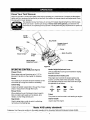
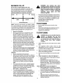
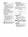
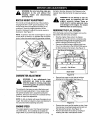
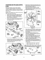
Operator's Manual
4.5 Horse Power
YARD VACUUM
Model No. 247.77010
CAUTION: Before using
this product, read this
manual and follow all
Safety Rules and
Operating Instructions.
•
•
•
•
•
Safety
Assembly
Operation
Maintenance
Parts
•
Espahol
Sears, Roebuck and Co., Hoffman Estates, IL 60179, U.S.A.
Visit our Sears website: www.sears.com/craftsmsn
Printed in U.S.A.
FORM NO. 770-10233D
(7/00)
Content
Page
Content
Page
Warranty
2
Service and Adjustments
12
Safety
3
Storage
14
Assembly
5
Troubleshooting
15
Operation
7
Parts List
16
Maintenance
10
Limited Warranty on Craftsman
Yard Vacuum
For one (1) year from the date of purchase, if this Craftsman Equipment is maintained, lubricated, and tuned up
according to the instructions to the operator's manual, Sears will repair or replace free of charge any parts found
to be defective in material or workmanship. Warranty service is available free of charge by returning Craftsman
equipment to your nearest Sears Service Center. In-home warranty service is available but a trip charge will
apply. This _/arranty applies only while this product is in the United States.
This Warranty does not cover:
Expendable items which become worn during normal use, such as spark plugs, air cleaners, belts, and oil
filters.
•
Tire replacement or repair caused by punctures from outside objects, such as nails, thorns, stumps, or glass.
•
Repairs necessary because of operator abuse, including but not limited to, damage caused by objects, such
as stones or metal debris, oversized stock, impacting objects that bend the frame or crankshaft, or overspeeding the engine.
Repairs necessary because of operator negligence, including but not limited to, electrical and mechanical
damage caused by improper storage, failure to use the proper grade and amount of engine oil, or failure to
maintain the equipment according to the instructions contained in the operator's manual.
•
Engine (fuel system) cleaning or repairs caused by fuel determine to be contaminated or oxidized (stale). In
general, fuel should be used within 30 days of its purchase date.
•
Equipment used for commercial or rental purposes.
TO LOCATE THE NEAREST SEARS SERVICE CENTER OR TO SCHEDULE SERVICE, SIMPLY CONTACT
SEARS AT 1-800-4-MY-HOME.
This warranty gives you specific legal rights and you may also have other rights, which vary from state to state.
PRODUCT
SPECIFICATION
Horsepower:
4.5 Horse Power
Engine
Oil Type
Engine
Oil Capacity
SAE 30
20 Ounces
;erial Number ...........................................................
Fuel Capacity:
1 1/2 Quarts
)ate of Purchase ......................................................
Spark Plug
Champion RJ-19LM
.030"
Spark Plug Gap
Model Number ....... .2.4Zt ,7..7...0..1.
_ .............................
Record both serial number and date of purchase and
keep in a safe place for future reference.
WARNING:
This symbol points out important safety instructions which, if not followed, could
endanger the personal safety and/or property of yourself and others. Read and follow all
instructions in this manual before attempting to operate this machine. Failure to comply with these
instructions may result in personal injury. When you see this symbol - heed its warning.
WARNING:
Engine Exhaust,
some of its constituents,
components contain or emit chemicals
and birth defects or other reproductive
and certain vehicle
known to State of California to cause cancer
harm.
DANG ER : This machine was built to be operated according to the rules for safe operation in this
manual. As with any type of power equipment, carelessness or error on the part of the operator can
result in serious injury. This machine is capable of amputating hands and feet and throwing objects.
Failure to observe the following safety instructions could result in serious injury or death.
TRAINING
Always wear safety glasses or safety goggles
during operation or while performing an
adjustment or repair, to protect eyes. Thrown
objects which ricochet can cause serious injury to
the eyes.
3.
Wear sturdy, rough-soled work shoes and closefitting slacks and shirts. Loose fitting clothes or
jewelry can be caught in movable parts. Never
operate this machine in bare feet or sandals.
Wear leather work gloves when feeding material
in the chipper chute,
4,
Before starting, check all bolts and screws for
proper tightness to be sure the machine is in safe
working condition. Also, visually inspect machine
for any damage at frequent intervals,
5.
Maintain or replace safety and instructions labels,
as necessary.
6. To avoid personal injury or property damage use
extreme care in handling gasoline. Gasoline is
extremely flammable and the vapors are
explosive. Serious personal injury can occur
when gasoline is spilled on yourself or your
clothes which can ignite. Wash your skin and
change clothes immediately.
a. Use only an approved'gasoline container.
b. Extinguish all cigarettes, cigars, pipes, and
other sources of ignition.
c. Never fuel machine indoors.
d. Never remove gas cap or add while the
engine is hot or running.
e. Allow engine to cool at least two minutes
before refueling.
f. Never over fill fuel tank. Fill tank to no more
than 1/2 inch below bottom of filler neck to
provide space for fuel expansion.
g. Replace gasoline cap and tighten securely.
h, If gasoline is spilled, wipe it off the engine
and equipment. Move machine to another
area. Wait 5 minutes before starting the
engine.
2.
1.
Read, understand, and follow all instructions on
the machine and in the manual(s) before
attempting to assemble and operate. Keep this
manual in a safe place for future and regular
reference and foP'ordering replacement parts.
2. Be familiar with all controls and their proper
operation. Know how to stop the machine and
disengage them quickly.
3. Never allow children under 16 years old to
operate this machine. Children 16 years old and
over should read and understand the operation
instructions and safety rules in this manual and
should be trained and supervised by a parent.
4. Never allow adults to operate this machine
without proper instruction.
5. Keep bystanders, helpers, pets, and children at
least 75 feet from the machine while it is in
6.
7.
8.
operation. Stop machine if anyone enters the
area.
Never run an engine indoors or in a poorly
ventilated area. Engine exhaust contains carbon
monoxide, an odorless and deadly gas.
Do not put hands and feet near rotating parts or in
the feeding chambers and discharge opening,
Contact with the rotating impeller can amputate
fingers, hands, and feet.
Never attempt to unclog either the feed intake or
discharge opening, remove or empty vacuum
bag, or inspect and repair the machine while the
engine is running. Shut the engine off and wait
until all moving parts have come to a complete
stop. Disconnect the spark plug wire and ground
it against the engine.
PREPARATION
1.
Thoroughly inspect the area where the
equipment is to be used. Remove all rocks,
bottles, cans, or other foreign objects which could
be picked up or thrown and cause personal injury
or damage to the machine.
3
i. Neverstorethemachine
orfuelcontainer
insidewherethereisanopenflame,spark,
orpilotlight(e.g.furnace,waterheater,
spaceheater,clothesdryer,etc.)
j. Toreducea firehazard,keepmachine
free
ofgrass,leaves,orotherdebrisbuild-up.
Cleanupoilfuelspillageandremove
anyfuel
soakeddebris.
k. Allowmachine
tocoolatleast5 minutes
beforestoring.
9.
10.
11.
12.
OPERATION
1.
2.
3.
4.
5.
6.
7.
8.
Do not put hands and feet near rotating parts or in
the feeding chambers and discharge opening.
Contact with the rotating impeller can amputate
fingers, hands, and feet.
Before starting the machine, make sure the chipper
chute, feed intake, and cutting chamber are empty
and free of all debris.
Thoroughly inspect all material to be shredded and
remove any metal, rocks, bottles, cans, or other
foreign objects which could cause personal injury
or damage to the machine.
If the impeller strikes a foreign object or if your
machine should start making an unusual noise or
vibration, immediately shut the engine off. Allow the
impeller to come to a complete stop. Disconnect
the spark plug wire, ground it against the engine
and perform the following steps:
a. Inspect for damage.
b. Repair or replace any damaged parts.
c. Check for any loose parts and tighten to
assure continued safe operation.
Do not allow an accumulation of processed
material to build up in the discharge area. This can
prevent proper discharge and result in kickback of
material through the feed opening.
Do not attempt to shred or chip material larger than
specified on the machine or in this manual.
Personal injury or machine damage could result.
Never attempt to unclog either the feed intake or
discharge opening while the engine is running.
Shut the engine off, wait until all moving parLs have
stopped, disconnect the spark plug wire and
ground it against the engine before clearing debris.
Never operate without vacuum bag and discharge
chute properly attached to the machine. Never
empty or change vacuum bag while the engine is
running. Zippered end of vacuum bag must be kept
closed at all times during operation.
13.
14.
15.
16.
Never operate without either the inlet nozzle or
optional hose attachment properly attached to the
machine. Never attempt to attach or change either
attachment while the engine is running.
Keep all guards, deflectors and safety devices in
place and operating properly.
Keep your face and body back and to the side of
the chipper chute while feeding material into the
machine to avoid accidental kickback injuries.
Never operate this machine without good visibility
or light. Always be sure of your footing and keep a
firm hold on the handles.
Do not operate this machine on a gravel surface.
Do not operate this machine while under the
influence of alcohol or drugs.
Muffler and engine become hot and can cause a
burn. Do not touch.
Never pick up or carry machine while the engine is
running.
MAINTENANCE
ANDSTORAGE
1.
Never tamper with safety devices. Check their
proper operation regularly.
2. Check bolts and screws for proper tightness at
frequent intervals to keep the machine in safe
working condition. Also, visually inspect machine
for any damage and repair, if needed.
3. Before cleaning, repairing, or inspecting, stop the
engine and make certain the impeller and all
moving parts have stopped. Disconnect the spark
plug wire and ground it against the engine to
prevent unintended starting.
4. Do not change the engine governor settings or
overspeed the engine. The governor controls the
maximum safe operating speed of the engine.
5. Maintain or replace safety and instruction labels, as
necessary.
6. Follow this manual for safe loading, unloading,
transporting, and storage of this machine.
7. Never store the machine or fuel container inside
where there is an open flame, spark or pilot light
such as a water heater, furnace, clothes dryer, etc.
8. Always refer to the operator's manual for proper
instructions on off-season storage.
9. If the fuel tank has to be drained, do this outdoors.
10. Observe proper disposal laws and regulations for
gas, oil, etc. to protect the environment.
IMPORTANT:This unit is shipped without gasoline or
oil in the engine. After assembly, see OPERATION
section of this manual for proper fuel and engine oil
fill-up.
NOTE: Reference to right and left hand side of the
Yard Vacuum is observed from the operating
position. See Figure 1.
This Yard Vacuum has been completely assembled
at the factory, except for the handle, bag, and blower
chute. These parts are shipped loose in the carton.
A pair of safety glasses and a 20-oz. bottle of engine
oil are also included in the carton. See Figure 1.
REMOVING
UNITFROMCARTON
•
•
Cut the corners of the carton.
Remove all loose parts.
Remove packing material. Lift unit from the rear
and discard foam blocks. Roll unit out of carton.
Check carton thoroughly for loose parts.
Blower
Chute
Upper
j/Handle
Rope
Guide
LOOSEPARTSIN CARTON
(seFigure1)
•
•
•
•
•
•
Handle Assembly
Bag
Blower Chute
Safety Glasses (Not Shown)
A 20-oz. Bottle of Engine Oil (may be located in
bag)
Operator's Manual
DISCONNECTING
SPARKPLUG
20-oz. Bottle
Before proceeding with assembly of your new Yard
Vacuum, disconnect the spark plug wire from the
spark plug and ground onto the retaining post on the
engine. This will prevent accidental starting of the
engine. See Figure 2.
of Engine Oil
Retaining Post
O
O
_g
Nuts
Plug Wire
Carriage
Screw
Figure 1
ATTACHING
THEHANDLE
•
Unfold the upper handle until it aligns with lower
handle. Make sure the rope guide is on the right
side of upper handle. See Figure 1.
Securethetwohandlesbytightening
theupper
wingnuts(carriage
boltsmustbeseatedproperly
intothehandle).
Remove
thehairpinclipsfromthehandle
brackets
andthecarriageboltsandwingnuts
fromthelowerhandle.SeeFigure3.
Placeeachbottomholeinlowerhandleoverthe
pinsonhandlebrackets
andsecurewithhairpin
clips.
Insertcarriage
boltsthruupperholein lower
handlefromtheoutsideandsecurewithwing
nuts.
Wing Nuts
oF
Lower
Handle
_
\
\
\
Figure 3
Loosen the wing nut that secures the rope guide
to the right side of upper handle.
Pull the starter rope out of the engine slowly and
slip the starter rope into the rope guide. Tighten
the wing nut.
ATTACHING
THEBAG
Grasp bag handle with one hand and pull locking
rod on mounting bracket with other hand toward
engine. See Figure 4.
Slip bag over the rim of the discharge opening
and release locking rod to secure bag in place.
Snap bag clip to the top of the lower handle.
Place the lower straps on the bag over the top of
lower handle, hooking them on the studs.
NOTE: The bag/chute switch button attached to the
mounting bracket must be fully depressed by the tip
of front tab on bag handle when securing the bag or
engine will not start.
ATTACHINGTHE BLOWERCHUTE
NOTE: The bag must be removed before installing
the blower chute.
Grasp blower chute with one hand and pull locking rod on mounting bracket with other hand
toward engine. See Figure 5.
Slip blower chute over rim of discharge opening and release locking rod to secure chute in
place.
•
Raise the nozzle height to the highest setting
when using the blower chute. Refer to nozzle
height adjustment in the ADJUSTMENT section.
NOTE: The bag/chute switch button attached to the
mounting bracket must be fully depressed by the tip
of front tab on the blower chute or engine will not
start.
Front
Blower
Lower
Handle_
Bag
Handle
Stud
Front
Tab
Locking /
Rod\
Locking
Rod
Front
Tab
To Engine
Figure 5
Switch
Stud_
Figure 4
Know Your Yard Vacuum
Read this operator's manual and safety rules before operating your Yard Vacuum. Compare the illustrations
below with your equipment to familiarize yourself with the location of various controls and adjustments. Save
this manual for future reference.
The operat on of any Yard Vacuum can resu t in fore gn objects being thrown into the eyes,
which can result in severe eye damage. Always wear safety glasses, provided with the
Yard Vacuum, for operating this equipment or while performing any adjustments or repairs on
it.
Starter
Handle
Bag_
Thro_le Control/
Choke Lever
_-
Wire
Blower Chute
Chute
Nozzle
Nozzle Height
Adjustment Level
Figure 6
OPERATING
CONTROLS
(see
Figure6)
Nozzle Height Adjustment Lever
Chipper Chute
Used to adjust the nozzle ground clearance ranging
from 5/8" to 3 3/4".
Allows twigs and small branches up to 1 1/2" in
diameter to be fed into the impeller for chipping.
Nozzle
Yard waste such as leaves and pine needles can be
vacuumed up through the nozzle for shredding.
Throttle Control / Choke Lever
This single lever controls the engine speed, stop
function, and the choke of the carburetor. Through
four separate positions on the lever from left to right,
the operation is as follows:
Catcher Bag
Collects shredded material fed in through the chipper
chute or vacuumed in through the nozzle.
Blower Chute
When attached to unit, the blower chute is used to
blow or scatter yard waste such as leaves, pine
needle, or small twigs across yard.
Bag Handle
Used to grasp bag in order to assist in attaching,
removing, and emptying bag.
Engine
Off
Slow/
Idle
Start]
Run
Choke
Primer
The primer is used to assist in cold starting an engine.
Starter Handle
Used to start the engine.
Meets ANSI safety standards
Craftsman Yard Vacuums conform to the safety standard of the American National Standards Institute (ANSI).
7
GASANDOILFILL-UP
WARNING: Use extreme care when
handling gasoline. Gasoline is extremely
flammable and the vapors are explosive.
Never fuel machine indoors or while the
engine is hot or running. Extinguish
cigarettes, cigars, pipes, and other
sources of ignition.
Oil (one 20-oz. bottle shipped with unit)
Only use high quality detergent oil rated with API
service classification SF, SG, or SH. Select the oirs
SAE viscosity grade according to the expected
operating temperature. Follow the chart below.
Colder
_--
5W30
I
32°F
_
Check the fuel level periodically to avoid running
out of gasoline while operating the Yard Vacuum.
If the unit runs out of gas as it is chipping, it may
be necessary to unclog the unit before itcan be
restarted. Refer to SERVICE AND
ADJUSTMENT section.
Warme
SAE 30
Oil Viscosity Chert
NOTE: Although multi-viscosity oils (5W30, IOW30,
etc.) improve starting in cold weather, they will result
in increased oil consumption when used above 32°F.
Check your engine oil level more frequently to avoid
possible engine damage from running low on oil.
Remove oil fill dipstick.
With the Yard Vacuum on level ground, use a
funnel to'fill engine with oil to FULL mark on
dipstick. Capacity is approximately 20 oz. Be
careful not to overfill. Overfilling will cause the
engine to smoke profusely and will result in poor
engine performance. The oil bottle packaged
with your Yard Vacuum contains 20 oz. of oil.
•
Check the oil level making certain not to rub the
dipstick along the inside walls of the oil fill tube.
This would result in a false dipstick reading. Refill
to FULL mark on dipstick, if necessary. Replace
dipstick and tighten.
•
Check oil level three times prior to starting engine
to be certain you've gotten an accurate dipstick
reading. Running the engine with too little oil can
result in permanent engine damage.
Gasoline
TOSTOPENGINE
•
Move throttle control lever to STOP or OFF
position.
Disconnect spark plug wire and ground it to the
post to prevent accidental starting while the
equipment is unattended.
•
•
•
•
Remove fuel cap from the fuel tank.
Make sure the container from which you will pour
the gasoline is clean and free from rust or foreign
particles. Never use gasoline that may be stale
from long periods of storage in its container.
Gasoline that has been sitting for any period
longer than four weeks should be considered
stale.
Fill fuel tank with clean, fresh, unleaded regular,
unleaded premium or reformulated automotive
gasoline only. DO NOT use Ethyl or high octane
gasoline. Do not use gasoline containing
METHANOL. Replace fuel cap.
To avoid engine problems, the fuel system
should be emptied before storage for 30 days or
longer. Drain the gas tank, start the engine and
let it run until the fuel lines and carburetor are
empty. Use fresh fuel next season. See
STORAGE section for additional information.
TOSTARTENGINE
operator isBe standing
near
WARNING:
sure no one
otherthe
thanYard
the
Vacuum while starting or operating. Do
not operate this unit unless the bag or
blower
chute
have
been properly
installed.
1.
Attach spark plug wire and rubber boot to spark
plug.
2.
The bag/chute switch button must be fully
depressed by the tip of front tab on bag handle
or blower chute for engine to start.
3.
Make sure bag/chute switch wire is connected to
engine and properly grounded.
4.
Gas tank should be filled 3/4 to full before starting.
5.
When temperature_is above 32 degrees F:
•
Move throttle control / choke level to START/
RUN position.
Depress the primer bulb firmly with your
thumb three times. Wait about two seconds
between each push. Do not use the primer to
restart a warm engine after a short shutdown.
See Figure 7.
When temperature is below 32 degrees F:
Move throttle control / choke lever on engine
to CHOKE position. (A warm engine may not
require choking.) See Figure 7.
If not using choke to start engine, move throttle control/choke lever to START/RUN position.
•
Depress the primer bulb firmly with your
thumb three times. Wait about two seconds
between each push.
8
•
ThrottleControl/
•
•
__
_er
•
Compress bag opening and fold inner flap over
opening.
Fold outer flap over inner flap and insert buttons
on the bag through metal outlets.
Twist the buttons to lock bag.
TO REMOVEBLOWER
CHUTE
Figure 7
6.
Standing behind the unit, grasp starter handle
and pull rope out until you feel a drag.
7.
Pull the rope with a rapid, continuous, full arm
stroke. Keep a firm grip on the starter handle.
Let the rope rewind slowly.
8,
Repeat, if necessary, until engine starts. When
engine starts, move throttle/choke lever gradually to START/RUN position.
9.
If engine falters, move control lever to CHOKE
position, then back to START/RUN position.
10. ALWAYS keep the throttle control in the START/
RUN position wlien operating the Yard Vacuum.
TOEMPTYBAG
Unhook bag straps from the lower handle and
unsnap bag clip from top of the lower handle.
See Figure 8.
Grasp bag handle with one hand and pull lock rod
on mounting bracket with other hand toward
engine to release.
Remove bag from over the rim of the discharge
opening. Refer to Figure 4.
Twist the two buttons on the back of the bag to
unlock and empty contents. See Figure 8.
Hold bag handle and bag clip while emptying the
contents.
Grasp blower chute with one hand and pull lock
rod on mounting bracket with other hand toward
engine to release. Refer to Figure 5,
Remove blower chute from over the rim of the
discharge opening.
OPERATION
Place both hands on top of upper handle to push unit
over yard waste. Yard waste such as leaves and pine
needles are vacuumed up through the nozzle and
shredded by the flail blades on the impeller assembly
and discharged into catcher bag or through blower
chute. Do not attempt to shred or chip any material
other than vegetation found in a normal yard (i.e.
branches, leaves, twigs, etc.). Avoid fibrous plants
such as tomato vines until they are thoroughly dried
out. Material such as stalks or heavy branches up to
1 1/2" in diameter may be fed into the chipper chute.
See Figure 9.
Chute
3u_ons
Inner Flap
Handle
Bag
Clil
'Nozzle
Figure 9
WARNING: Do not attempt to shred,
chip, or vacuum any material larger than
specified on the machine or in this
manual. Personal injury or damage to
the machine could result.
Outer Fla
IMPORTANT:The flail screen located inside the
housing in the discharge area, If the flail screen
becomes clogged, stop engine and remove and clean
as instructedin the SERVICE AND ADJUSTMENT
section.
Figure 8
MAINTENANCE
SCHEDULE
be
_
_
_
Lubrication
o
Clean equipment
Check engine oil
w
z
Change engine oil
Service air cleaner
z
ILl
Service spark plug
Service muffler
_
Clean engine
GENERAL
RECOMMENDATIONS
•
•
CLEANEQUIPMENT
Clean the Yard Vacuum thoroughly after each
Always observe safety rules when performing any
maintenance.
The warranty on this Yard Vacuum does not
cover items that have been subjected to operator
abuse or negligence. To receive full value from
the warranty, operator must maintain the
equipment as instructed in this manual.
Some adjustments will need to be made
periodically to maintain your equipment properly.
Follow the maintenance schedule.
use.
•
•
NOTE: Cleaning with a forceful spray of water is not
recommended as it could contaminate the fuel
system.
Periodically check all fasteners and make sure
they are tight.
A
CHECKENGINE01L
WARNING: Always stop the engine and
disconnect and ground the spark plug
wire before performing any maintenance
or adjustments,
•
•
LUBRICATION
•
•
Wash the bag periodically with water. Allow to
dry thoroughly in the shade.
If the flail screen becomes clogged, remove and
clean as instructed in the SERVICE AND
ADJUSTMENT section.
Remove oil fill dipstick.
Check oil level on dipstick. Level should be at
FULL mark.
Replace dipstick and tighten.
CHANGE
ENGINEOIL
Wheels- Place a few drops of SAE 30 oil on each
shoulder screw once a season.
Refer to •.
Nozzle height adjustment levers- Lubricate
nozzle height adjustment levers with light oil.
Refer to Figure 6.
Locking Rod- Lubricate the lock rod and
compression springs which attach to the
mounting bracket. Refer to Figure 4.
Only use high quality detergent oil rated with API
service classification SF, SG, or SH. Select the
oil's SAE viscosity grade according to the
expected operating temperature. Refer to
operation section for viscosity chad.
Stop engine and wait several minutes before
checking oil level. With engine on level ground,
the oil must be to FULL mark on dipstick.
Change engine oil after the first five hours of
operation, and every twenty-five hours
thereafter.
10
TO DRAINOIL
SERVICESPARKPLUG
Drain oil while engine is warm. Follow the instructions
given below.
•
•
Drain the gas tank, start the engine and let it run
until the fuel line and carburetor are empty.
Remove oil fill dipstick.
Tip unit on its side to drain through the oil fill tube.
When engine is drained of all oil, refill with
approximately 20 oz. of fresh oil. Refer to Gas
And Oil Fill-up in OPERATION section.
Replace dipstick.
•
•
Clean the spark plug and reset the gap to .030" at
least once a season or every 50 hours of
operation. See Figure 10. Spark plug
replacement is recommended at the start of each
season. Refer to engine parts list for correct
spark plug type.
NOTE: Do not sandblast spark plug. Spark plug
should be cleaned by scraping or wire brushing and
washing with a commercial solvent.
.030" Feeler Gauge
SERVICEAIRCLEANER
The air cleaner prevents damaging dirt, dust, etc.,
from entering the carburetor and being forced into the
engine and is important to engine life and
performance. The air cleaner consists of a foam filter.
Never run the engine without an air cleaner
completely assembled.
Figure 10
To ServiceAir Cleaner:
•
•
•
•
•
•
Remove foam filter from plastic housing on top of
engine.
Wash in water and detergent solution, and
squeeze (do not twist) until all dirt is removed.
Rinse thoroughly in clear water.
Wrap in a clean cloth and squeeze (do not twist)
until completely dry, or allow to air dry.
Saturate with engine oil and squeeze to distribute
oil and remove excess oil.
Replace foam filter in plastic housing
SERVICEMUFFLER
•
•
A
NOTE: ff the foam filter is tom or damaged in any
way, replace it.
_lb
Inspect muffler periodically, and replace if
necessary.
If your engine is equipped with a spark arrester
screen assembly, remove after every 50 hours of
use for cleaning and inspection. Replace if
damaged.
muffler
and WARNING:
nearby areas
may exceed
ARNING:
Temperature
of
150 ° F(65°C). Avoid these areas.
WARNING: Do not operate the Yard
Vacuum without a muffler or tamper with
the exhaust system. Damaged mufflers
or spark arresters could create a fire
hazard.
CLEANENGINE
Clean engine by removing dirt and debris with a
cloth or brush.
Frequently remove grass clippings, dirt, and
debris from cooling fins, air intake screen, levers,
and linkage. This will help ensure adequate
cooling and engine speed.
11
WARNING: Do not at any time make any
adjustment to the unit without first
stopping
engine
and disconnecting
spark plug wire.
too fast or too slow, take your Yard Vacuum to the
nearest Sears Service Center for repair and adjustment.
WARNING: Do not attempt to alter the
engine speed by tampering with the
engine's governor linkage. Doing so
could result in serious personal injury
and damage to the engine. The engine
RPM has been set at the factory.
NOZZLEHEIGHTADJUSTMENT
The nozzle can be adjusted to any of five positions,
ranging from 5/8" to 3 3/4" ground clearance. The
nozzle height has to be adjusted according to the
conditions. Move the height adjustment levers
forward or backward to adjust the nozzle upward or
downward. See Figure 11.
REMOVING
THEFLAILSCREEN
If the discharge area becomes clogged, remove the
flail screen and clean area as follows.
NOTE: In general, raise the nozzle height to vacuum
a thick layer of leaves or to operate with the blower
chute. Lower the nozzle height for smoother surfaces.
•
•
•
Stop the engine. Make certain the chipper
shredder vacuum has come to a complete stop.
Disconnect and ground the spark plug wire
before unclogging the discharge chute.
Remove the vacuum bag or blower chute from
the unit as instructed in the OPERATION section
to obtain access to flail screen. See Figure 12.
Adjustment
Lever
REAR VIEW
Figure 11
Figure 12
CARBURETOR
ADJUSTMENT
Remove hex screw on right side of unit that
attaches to the flail screen. See Figure 13.
WARNING: If any adjustments (e.g.
carburetor) are made to the engine
while the engine is running, keep clear
of all moving parts. Be careful of heated
surfaces and muffler.
The carburetor has been pre-set at the factory and
should not require adjustment. If your engine does
not operate properly due to suspected carburetor
problems, take your Yard Vacuum to a Sears Service
Center for repair and adjustment.
_Remove
Hex Screw
NOTE: A dirty air cleaner will cause the engine to run
rough, Becertainaircleaneriscleanandattachedto
the carburetor before adjusting carburetor,
Figure 13
Remove hex screw and flat washer on top of rear
housing near mounting bracket and the lock nut
that secures flail screen. See Figure 12.
Remove and clean the screen by scraping or
washing with water. Reinstall the screen.
ENGINESPEED
The engine speed on your Yard Vacuum has been
set at the factory. Do not attempt to increase the
engine RPM. If you think that the engine is running
12
Remove lock nut that secures flail screen to the
lower housing. The flail screen does not have to
be removed. Refer to Figure 12.
Remove the hex bolt, lock washer, and flat
washer that secure the impeller assembly to the
crankshaft. See Figure 16.
SHARPENING
ORREPLACING
CHIPPER
BLADE
Because the engine on this unit has a tapered
crankshaft, a special impeller removal tool (part
number 753-0638) is required to remove the impeller
assembly• For further assistance, contact your Sears
Service Center.
Upper
NOTE: When tipping the unit, empty the fuel tank and
keep engine spark plug side up.
Impeller
Disconnect and ground the spark plug wire.
Remove the front hubcaps, shoulder screws,
wave washers, and bell washers that attach to
the front wheels. See Figure 14.
Remove the shoulder screws that go through the
pivot arms and height bracket adjusters to the
front support brace.
Hex Bolt
Lock Washer
Flat Washer
Flail
Blade
BOI-I'OM VIEW
Figure 16
Bracket
Adjuster
Apply lubricant to the threads of impeller removal
tool and then thread the tool into the crankshaft.
Stop when the impeller assembly can move on
the crankshaft.
Remove the impeller assembly from the
crankshaft. Unthread the impeller removal tool
from the impeller assembly.
Remove the chipper blade using a 3/16" allen
wrench on the outside of the blade and 1/2"
wrench on the underside of impeller assembly.
Replace or sharpen chipper blade.
When sharpening blade, protect hands by using
gloves and follow the original angle of grind.
Reassemble by performing the previous steps in
reverse order.
/
Shoulder
Screw
Figure 14
Remove the three screws on the upper housing
that secure the nozzle cover and the nine screws
that secure the lower housing to the upper
housing. See Figure 15.
• Tighten blade screws to 210 - 250 in-lbs.
• Tighten impeller bolt to 375 - 425 in-lbs.
NOTE: Make certain chipper blade is reassembled
with the sharp edge facing upward. See Figure 17.
f f,,,.u...=_
•
Lower
Housing
Screws
_Chipper
/
deFlai
I
_
-
_lmpeller
_J_ _._
Screws
Figure 15
Figure 17
13
__
Assembly
Prepare your Craftsman Yard Vacuum for storage at
the end of the season or if the unit will not be used for
30 days or longer. A yearly check-up by your local
Sears Service Center is a good way to ensure that the
unit runs properly next season.
NOTE: Fuel stabilizer is an acceptable alternative in
minimizing the formation of fuel gum deposits during
storage.
YardVacuum
•
•
•
•
Run engine at least 10 minutes after adding
stabilizer to allow the stabilizer to reach the
carburetor.
•
Do not drain the gas tank and carburetor if using
fuel stabilizer. Drain all the oil from the
•
•
Clean the equipment thoroughly.
Wipe equipment with an oiled rag to prevent rust.
Use a light oil or silicone to wipe.
Service the engine following instructions below.
Store unit in a clean, dry area. Do not store next to
corrosive materials such as fertilizer.
crankcase (this should be done after the engine
has been operated and is still warm) and refill the
crankcase with fresh oil.
Engine
If you have drained the fuel tank, protect the inside of
the engine as follows:
IMPORTANT:It is important to prevent gum deposits
from forming in essential fuel system parts such as
the carburetor, fuel filter, fuel hose, or tank during
storage. Also, alcohol blended fuels (called gasohol or
using ethan_'or methanol) can attract moisture which
leads to separation and formation of acids during
storage. Acidic gas can damage the fuel system of an
engine while in storage.
•
Drain the fuel tank.
•
Start the engine and let it run until the fuel lines
and carburetor are empty.
Drain carburetor.
•
Remove spark plug, pour approximately 1/2
ounce (approximately one tablespoon) of engine
oil into cylinder and crank slowly to distribute oil.
Replace spark plug.
Other
•
To avoid engine problems, the fuel system should be
emptied before storage of 30 days or longer. Follow
these instruction:
•
Add stabilizer to gasoline in fuel tank or storage
container.
Always follow the mix ratio found on stabilizer
container.
Do not store gasoline from one season to
another.
Replace the gasoline can if it starts to rust. Rust
and/or dirt in the gasoline will cause problems.
Store unit in a clean, dry area. Do not store next
to corrosive materials, such as fertilizer.
NOTE: If storing in an unventilated or metal storage
shed, be certain to rustproof the equipment by coating with a light oil or silicone.
Never use engine or carburetor cleaner products
in the fuel tank or permanent damage may occur.
14
Problem
Possible Cause(s)
Corrective Action
Engine fails to start
1.
Fuel tank empty or stale fuel.
1.
Fill tank with clean, fresh gasoline. Fuel will not
last over thirty days unless a fuel stabilizer is
added.
2.
3,
Spark plug wire disconnected.
Cannot pull recoilcord.
2.
3.
4.
5.
6.
Choke not in ON position.
Faulty spark plug.
Safety switch not depressed,
4.
5.
6.
7.
Safety switch wire is not
connected to engine or not
properly grounded.
7.
Connect wire to spark plug.
Obstruction lodged in impeller. Disconnect
spark plug wire and remove lodged object.
Move CHOKE to ON position.
Clean, adjust gap or replace.
Safety switch must be depressed by the front
tab on the bag handle when securing the bag.
Connect safety switch wire to engine connector
and ground to mounting bracket,
1,
2.
3.
Spark plug wire loose.
Unit running on CHOKE.
Blocked fuel line or stale fuel.
1,
2.
3.
4.
Water or dirt in fuel system.
4,
5.
6,
Carburetor out of adjustment,
Lowengine RPM.
5.
6.
Too much vibration
1.
Loose parts or damaged
impeller.
1.
Stop engine immediately and disconnect spark
plug wire. Have unit serviced by a Sears
Service Center.
Engine overheats
1.
2.
Carburetor not adjusted
Engine oil level low
1.
2.
Contact your Sears Service Center.
Fill crankcase with proper selection of oil.
Unit does not
discharge
1.
Discharge chute clogged.
1.
2.
2.
3.
4.
Foreign object lodged in
impeller.
Lowengine RPM.
Vacuum bag is full.
Stop engine immediately and disconnect spark
plug wire. Clean flail screen and inside of
discharge opening. See Maintenance section of
this manual.
Stop engine immediately and disconnect spark
plug wire. Remove lodged object.
Always run engine at full throttle.
Empty bag.
1.
2.
Low engine RPM.
Chipper blade dull.
1.
2.
Loss of power;
operation erratic
Ib
Rate of discharge
slows considerably or
composition of
discharged material
changes
3.
4.
Connect and tighten spark plug wire.
Move choke lever to OFF position.
Clean fuel line; fill tank with clean fresh
gasoline. Fuel will not last over thirty days
unless a fuel stabilizer is used.
Disconnect fuel line at carburetor to drain fuel
tank, Refill with fresh fuel
Contact your Sears Service Center.
Always run engine at full throttle.
Always run engine at full throttle.
Replace chipper blade or see your Sears
Service Center.
NOTE: For repairs beyond the minor adjustments listed above, please contact your local Sears Service Center.
15
Sears Craftsman
4.5 H.P. Yard Vacuum
Model 247.77010
4
\
12
\
11
_
5
6
\
\
13
I
19_
jl
8
15
€=
2O
16\
\\
\
\
22
16
Sears Craftsman
Ref.
No.
Pad No.
4.5 H.P. Yard Vacuum
Model 247.77010
Ref.
No.
Part Description
Part No,
Part Description
1,
725-1700
Switch Cover
21.
710-1054
Hex Screw 5/16-24 x 1.0
2.
725-3166
Safety Switch
22.
781-0490
3.
710-0224
23.
736-0119
4.
5.
629-0920
710-0604A
Hex Washer Screw #10-16 x .50
Wire Harness
Chipper Blade
Lock Washer 5/16
24.
712-0411
Hex Lock Nut 5/16-24
Hex Washer Screw 5/16-18 x .625
25.
681-0152
6.
714-0104
Cotter Pin
736-0264
Flat Washer.330 ID x.630 OD
719-0329
781-0735
Impeller Assembly
Flail Blade
7.
26.
27.
8.
9.
732-0962
781-0778
28.
711-1401
29.
715-0166
10.
747-1153
Compression Spring
Mounting Bracket
Lock Rod
11.
710-3008
Hex Cap Screw 5/16-18 x .75
30.
31.
736-0247
736-0217
12.
681-0122
Chipper Chute Assembly
32.
710-0818
13.
726-0454
33.
681-0154
14.
15.
736-0607
710-0502A
U-Clip Lock Nut 5/16-18
External Lock Washer 5/16
34.
35.
710-3038
781-0721
16.
710-0969
Hex Washer Screw 3/8-16 x 1.25
Screw #12-16 x 1.0
36.
712-3004A
Lower Housing
Lock Nut 5/16-18
17.
710-3195
Hex Cap Screw 5/16-18 x 4.5
18.
19.
710-3025
710-0604A
Hex Cap Screw 5/16-18 x .625
Hex Washer Screw 5/16-18 x .625
37.
38.
731-1905
712-0158
Nozzle Cover
Lock Nut 5/16-18
39.
731-1613
Safety Switch Cover
20.
781-0720
Upper Housing
Pin Clip
Clevis Pin
Spiral Pin
Fiat Washer.375 ID x 1.25 OD
Lock Washer 3/8
Hex Cap Screw 3/8-24 x 2.0
Screen Assembly
Hex Cap Screw 5/16-18 x .875
NOTE: For painted parts, please refer to the list of color codes below. Please add the applicable color code, wherever needed,
to the part number to order a replacement part. For instance, if a part, numbered 70O-xxxx, is painted polo green, the part number to order would be 700-xxxx-0689.
Polo Green:
0689
Oyster Grey:
0662
Powder Black:
0637
17
Sears Craftsman
4.5 H.P. Yard Vacuum
Model 247.77010
7
9
\
\
\
11
I,
i
13
12
\
15
12
14
16
Y
12
23
\
17
12_
/
7 25
26
\
29
22
14
18
17
20
27
34
28
33
\
18
21
Sears Craftsman
Ref.
No.
4.5 H.P. Yard Vacuum
Pad No.
Model 247.77010
Part Description
Ref.
No,
Part No.
Part Description
1.
720-0295
Foam Grip
18.
736-0105
Bell Washer.401 ID x.870 OD
2.
3.
749-0438C
720-0279
Upper Handle
Knob
19.
20.
734-1992
738-1015
Wheel 9 x 2
4.
710-1205
Eye Bolt
21.
731-0981A
Hubcap
5.
6.
720-0276
710-1174
Handle Knob 5/16-18
22.
781-0725
Front Wheel Support Brace
23.
749-0907A
781-0765
781-0766
Hgt Bracket Adjuster LH
7.
Carriage Bolt
Lower Handle
8,
664-0094
Bag Assembly
Studs
25.
26.
748-0417
747-1100
Shoulder Screw 3/8-16
Hgt Bracket Adj RH (Not Shown)
Pivot Arm
9.
711-1293
10.
11.
712-0397
710-0703
Wing Nut 1/4-20
27.
738-1017
Carriage Screw 1/4-20 x .75
28.
732-0864
12.
726-0453
13.
781-0777
Lock U-Clip Nut 3/8-16
Rear Wheel Support Brace
29.
30.
710-0653
782-0578
14.
712-3004A
Flange Lock Nut 5/16-18
31.
710-0642
15.
16.
714-0104
661-0155
Cotter Pin
32.
734-1978
Spring Lever Support Bracket
Hex Washer Screw 1/4-20 x .75
Wheel 8 x 2
33.
17.
_'Handle Bracket Ass"y LH
Handle Height Adjuster
Shoulder Screw 3/8-16
Height Adjuster Plate Spring
Hex Washer Screw 1/4-20 x .375
736-0232
Wave Washer .531 ID x .781 OD
681-0156
Hndle Brkt Ass"y RH (Not Shown)
34.
738-0213
Shoulder Screw
710-3025
Hex Cap Screw 5/16-18 x .625
35.
631-0090
Blower Chute Assembly
NOTE: For painted parts, please refer to the list of color codes below. Please add the applicable color code, wherever needed,
to the part number to order a replacement part. For instance, if a part, numbered 700-xxxx, is painted polo green, the part number to order would be 700-xxxx-0689.
Polo Green:
0689
Oyster Grey:
0662
Powder Black:
0637
19
Sears Craftsman 4.5 H.P. Engine Model No. 143.014500
For Yard Vacuum Model 247.77010
_-.,--_370K
31°
07
73
238
2O
Sears Craftsman 4.5 H.P. Engine Model No. 143.014500
For Yard Vacuum Model 247.77010
Ref.
No.
1.
2.
6.
7.
12A.
14.
15.
16.
17.
18.
19.
20.
30.
40.
41.
42.
43.
45.
46.
48.
50.
52.
69.
70.
72.
72A.
73.
75.
80.
81.
82.
83.
86.
89.
90.
92.
93.
100.
101.
103.
104.
110.
110A.
119.
120.
125.
126.
130.
135.
150.
151.
151A.
169.
172.
Pa_ No,
37266
26727
33734
37247
36558
28277
30589
34839A
31335
651018
36281
32600
37527
40027
40028
40025
40026
40006
40007
20381
36777
32610A
27241
37460
29914
35261
36249B
30572
28534
28833
27897
30574A
30590A
30591
30588A
650488
611004
611112
650815
650816
34443C
610118
651007
37480
37574
37331
36787
36825
37288
37289
6021A
35395
31672
31673
40017
36783
36784
Ref.
No.
Part Description
174.
178.
179.
182.
184.
185.
186.
200,
203.
204.
206.
207.
209.
215.
223.
224.
238.
239.
240.
245.
245A.
250.
260.
261.
262.
275.
277.
279.
279A.
280.
285.
287.
290.
292.
300.
301.
305.
306.
307.
309.
310.
313.
324.
370.
370A.
370B.
370C.
370K.
370R.
370S.
380.
390.
400.
416.
417.
900.
Cylinder
Dowel Pin
Breather Element
Breather Ass'y
Breather Cover & Tube
Washer
Governor Rod
Governor Lever
Governor Lever Clamp
Torx Screw 8-32 x 19/64"
Extension Spring
Oil Seal
Crankshaft
Piston, Pin & Ring Set (Std)
Piston, Pin & Ring Set (.010" OS)
Piston & Pin Ass'y (Std)
Piston & Pin Ass'y (.010" OS)
Ring Set (Std)
Ring Set (.010" OS)
_"Piston Pin Retaining Ring
Connecting Rod Ass'y
Connecting Rod Bolt
Valve Lifter
Camshaft
Oil Pump Ass'y
Mounting Flange Gasket
Mounting Flange
Oil Drain Plug
Oil Drain Plug
Drain Plug Gasket
Oil Seal
Governor Shaft
Washer
Governor Gear Ass'y
Governor Spool
Screw 1/4-20 x 1-1/4
Flywheel Key
Flywheel
Bell Washer
Flywheel Nut
Solid State Ignition
Spark Plug Cover
Torx Screw 10-24 x 15/16"
Cam Bushing
Ground Wire
Ground Wire
Cylinder Head Gasket
Cylinder Head
Exhaust Valve
Intake Valve
Screw 5/16-18 x 1-1/2"
Resistor Spark Plug
Valve Spring
Valve Spring Cap
Intake Valve Seal
Valve Cover Gasket
Valve Cover
21
Pe_ No.
30200
29752
30593
6201
26756
36785
34337
32264A
31342
651029
610973
34336
30200
32410
650451
36786
650806
34338
37115
37116
37117
37118
37151
30200
650831
36790A
650988
650737
650902
37171A
35000A
650926
34357
26460
35586
36246
35577
36996
35499
650562
35578
34080
33177
37269
36261
36507
37505
36695
37317
37504
640278
590737
36792B
36085
650821
750856A
Part Description
Screw 10-24 x 9/16"
Nut & Lock Washer 1/4-28
Retainer Clip
Screw 1/4-28 x 7/8"
Carburetor To Intake Pipe Gasket
Intake Pipe
Governor Link
Control Bracket
Compression Spring
Torx Screw 5-40 x 7/16"
Terminal
Throttle Link
Screw 10-24 x 9/16"
Control Knob
Screw 1/4-20 x 1"
Intake Pipe Gasket
Screw 10-32 x 1/2"
Air Cleaner Gasket
Air Cleaner Body
Air Cleaner Filter
Pre-Air Cleaner Filter
Air Cleaner Cover
Blower Housing
Screw 10-24 x 9/16"
Screw 1/4-20 x 1/2"
Muffler
Screw 1/4-20 x 2-5/16"
Screw 1/4-20 x 1/2"
Screw 10-32 x 7/16"
Heat Shield
Starter Cup
Screw 8-32 x 21-64"
Fuel Line
Fuel Line Clamp
Fuel Tank
Fuel Cap
Oil Fill Tube
O-Ring
O-Ring
Screw 10-32 x 1/2"
Dipstick
Spacer
Terminal
4.6 HP Label
Lubrication Label
Control Label
Primer Label
Starter Label
Warning Label
Primer Label
Carburetor
Rewind Starter
Gasket Set
Spark Arrestor
Screw 10-32 x 1/2"
Short Block
Sears Craftsman 4.5 H.P. Engine Model No. 143.014500
For Yard Vacuum Model 247.77010
!
011
/
20A
29
2O
t
I
.30
22
Sears Craftsman 4.5 H.P. Engine Model No. 143.014500
For Yard Vacuum Model 247.77010
Ref.
No,
Pad No.
1.
2.
631615
631767
3.
Ref.
No.
Part Description
Part Description
Part No.
Float Bowl
Float Shaft
Throttle Shaft & Lever Assembly
25.
631867
640278
Throttle Return Spring
Carburetor
27.
28.
631024
632019
4.
631184
Dust Seal Washer
29.
631028
Float Bowl O-Ring
5.
6.
631183
640070
Dust Seal
Throttle Shutter
30.
31.
631021
631022
7.
650506
Shutter Screw
35.
640259
Inlet Needle, Seat, & Clip
Spring Clip
Primer Bulb
10.
630973
Choke Shaft & Lever Assembly
36.
632735
Main Nozzle Tube
11.
632045
14.
16.
640150
631807
Choke Return Spring
Choke Shutter
37.
40.
632547
640050
Fuel Fitting
44.
27110A
Main Nozzle Tube O-Ring
High Speed Bowl Nut
Bowl Nut Washer
17.
651025
Idle Speed Screw
47.
630748
Idle Mixture Well Plug
18.
630766
640027
640053
48.
60.
631027
632760
Atmospheric Vent Plug
20.
20A.
Tension Spring
Idle Restrictor Screw
ddle Jet Cap
23
Float
Repair Kit
Sears Craftsman 4.5 H.P. Engine Model No. 143.014500
For Yard Vacuum Model 247,77010
Ref.
No.
13
.8
9
2_
Part No,
Part Description
1.
590599A
2.
590600
3.
4.
590696
590601
5.
590697
Brake Spring
6.
7.
590698
Starter Dog
Dog Spring
8.
590699
590700
9.
590694
Pulley & Rewind Spring Ass'y
Recoil Starter
11.
590695
Starter Housing Ass'y
12.
590535
13.
590701
Starter Rope
Starter Handle
Spring Pin
Washer
Retainer
Washer
_j5
O
12
Ref,
No.
Part No.
Part Description
1.
590737
Rewind Starter
3.
590740
Retainer
6.
7.
590616
590617
Starter Dog
8,
590618A
Pulley & Rewind Spring Ass'y
11.
12.
590687A
13,
590535
590701
Starter Housing Ass'y
Starter Rope
Starter Handle
14.
590760
Spring Clip
Dog Spring
24
In U.S.A. or Canada
for in-home major brand repair service:
Call 24 hours a day, 7 days a week
1-800-4-MY-HOME sM(1-800-469-4663)
Para pedir servicio de reparacibn
a domicilio - 1-800-676-5811
Au Canada pour tout le service ou les pi_ces - 1-800-469-4663
For the repair or replacement parts you need:
Call 6 a.m. - 11 p.m. CST, 7 days a week
PartsDirect
1-800-366-PART
(1-800-366-7278)
Para ordenar piezas con entrega a domicilio
- 1-800-659-7084
For the location of a Sears Service Center in your area:
Call 24 hours a day, 7 days a week
1-800-488-1222
To purchase or inquire about a Sears Maintenance Agreement:
Call 7 a.m. - 5 p.m. CST, Monday - Saturday
1-800-827-6655
SEARS
HomeCentral