1
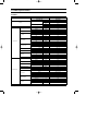
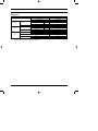
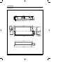
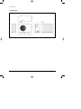
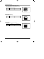
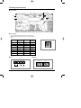
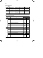
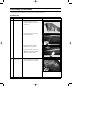
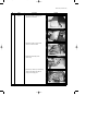
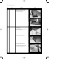
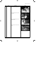
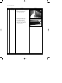
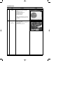
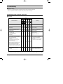
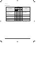
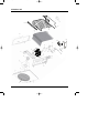
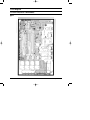
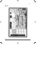
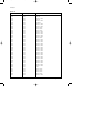
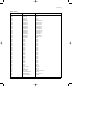
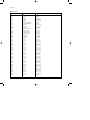
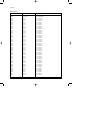
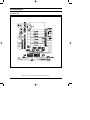
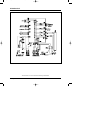
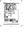
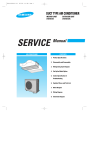
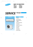
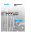
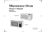
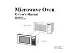
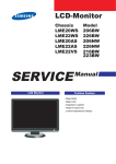
DB98_15108A(1)_CO
10/15/03 3:04 PM
Page 3
DUCT TYPE AIR CONDITIONER
INDOOR UNIT
OUTDOOR UNIT
DH070EZM
UH070EZMC
SERVICE
Manual
AIR CONDITIONER
CONTENTS
1. Product Specifications
2. Installation
3. Disassembly and Reassembly
4. Refrigerating Cycle Diagram
5. Troubleshooting
6. Exploded Views and Parts List
7. PCB Diagram
8. Wiring Diagram
9. Schematic Diagram
DB98_15108A(1)_1
10/15/03 3:06 PM
Page 1
1. Product Specifications
1-1 Table
INDOOR UNIT
MODEL
OUTDOOR UNIT
Cooling
Capacity
Heating
Running Current
Fan Speed
Air Circulation
Indoor Unit
Noise Level
(Sound Pressure)
Heat Exchanger
Fan
Dimension
Weight
Power Input
Running Current
Fan Speed
Fan
23,900
Watts
7,000
Btu/hr
26,300
Watts
7,700
Cooling
Watts
200
Heating
Watts
200
Cooling
A
1.0
Heating
A
1.0
H.H
r.p.m
1,050
Hi
r.p.m
950
Mid
r.p.m
900
Low
r.p.m
850
U-High
m3/min
19.5
High
m3/min
17.5
Mid
m3/min
16.5
Low
m3/min
15.5
High
dB(A)
46
Mid
dB(A)
45
Low
dB(A)
D-fin coil
Row x Stages x Fin Pitch
2 x 10 x 1.7(1,100mm)
Type
Sirocco
Motor Output
W
97
H
mm
260
W
mm
1,340
D
mm
600
Net / Gross
kg
41 / 47
Cooling
Watts
2,250
Heating
Watts
2,250
Cooling
A
11.2
Heating
A
11.2
High
r.p.m
820
Low
r.p.m
400
dB(A)
Type
Motor Output
W
Heat Exchanger
SHV33YC6-G
kW
2.22
Protection
Internal
Type
wave fin coil
Row x Stages x Fin Pitch
Face Area
2 x 24 x 1.5(900mm)
m2
Control
Refrigerant
0.55
EEV
Type
Charge
Samsung Electronics
60
Rotary
Model
Capacity
57
Propeller Fan
Type
Compressor
44
Type
Sound Pressure Level
Outdoor Unit
UH070EZMC
Btu/hr
1ø, 220-240V~, 50Hz
Power Supply
Power Input
DH070EZM
R-22
kg
2.1
1
DB98_15108A(1)_1
10/15/03 3:06 PM
Page 2
Table(cont.)
INDOOR UNIT
MODEL
Outdoor Unit
Dimension
Weight
Indoor Unit
Condition
Outdoor Unit
Pipe O.D. Size
Piping
DH070EZM
OUTDOOR UNIT
UH070EZMC
H
mm
638
W
mm
880
D
mm
310
Net / Gross
kg
67 / 72
Cool(DB/WB)
˚C
27 / 19
Heat(DB/WB)
˚C
20 / 15
Cool(DB/WB)
˚C
35 / 24
Heat(DB/WB)
˚C
7/6
Liquid
mm(inch)
9.52(3/8")
Gas
mm(inch)
15.88(5/8")
Height
m
Max. 15
Pipe Length
m
Max. 30
Connection Method
Between
Flare
Notice : This model is tested under the external static pressure of 4mmAq.
Notice : Air Flow rate : Fan Step Control : Low → Mid → High → Ultra High
2
Samsung Electronics
DB98_15108A(1)_1
10/15/03 3:06 PM
Page 3
1-2 Dimensions
1-2-1 Indoor Unit
(Unit : mm)
Samsung Electronics
3
DB98_15108A(1)_1
10/15/03 3:06 PM
Page 4
Product Specifications
1-2-2 Outdoor Unit
310
(Unit : mm)
(Rear View)
638
(Front View)
660
880
4
Samsung Electronics
DB98_15108A(1)_1
10/15/03 3:06 PM
Page 5
2. Installation
2-1 Assigning Address to Indoor Unit
1. Before installing the indoor unit, assign an address to the indoor unit according to the air conditioning system plan.
2. The address of the indoor unit is assigned by adjusting MAIN(SW02) and RMC(SW01) rotary switches.
K1 K2 K3 K4
SW03
K5 K6 K7 K8
SW04
K9 K10 K11 K12
SW05
SW02 MAIN
SW01 RMC
3. The MAIN address is for communication between the indoor unit and the outdoor unit.
Therefore, you must set it to operate the air conditioner properly.
4. It is required to set the RMC address if you install the wired remote controller and/or the centralized controller.
5. If you install optional accessories such as the wired remote controller, centralized controller, etc. see an appropriate
installation manual.
6. If an optional accessory is not installed, you do not have to set the RMC address. However, adjust K1 and K2 switches of
the SW03 DIP switch to "ON" position in this case.
7. Set the MAIN address by adjusting the rotary switch(SW02) from 0 to F. Each indoor unit connected to the same outdoor
unit must have different address.
7. i. e. If an indoor unit does not have an optional accessory and its
MAIN address is "4".
K1 K2 K3 K4
SW03
K5 K6 K7 K8
SW04
K9 K10 K11 K12
SW05
SW02 MAIN
Samsung Electronics
SW01 RMC
5
DB98_15108A(1)_1
10/15/03 3:06 PM
Page 6
2-2 Additional Functions
■ Compensation for lost temperature in heating operation
■ • Reduces the difference between an actual room temperature and a sensed
■ • temperature by the air conditioner when heating.
Switch No.
Switch ON
Switch OFF
K5
2°C compensation
5°C compensation
K5 K6 K7 K8
SW04
■ Adjusting filter cleaning cycle
■ • You can adjust the cycle for filter sign indicator.
Switch No.
Switch ON
Switch OFF
K6
1000 hours
2000 hours
K5 K6 K7 K8
SW04
■ Hot water heater
■ • You must adjust the K7 when you install the hot water heater.
6
Switch No.
Switch ON
Switch OFF
K7
No use of hot water heater
Use of hot water heater
K5 K6 K7 K8
SW04
Samsung Electronics
DB98_15108A(1)_1
10/15/03 3:06 PM
Page 7
2-3 Setting Up Option Switches
■ Option Switch
Rotary Switch
Display
Key
■ Rotary Switch
■ You should display that how many indoor units are connected to the
outdoor unit. Refer to the table below, then turn the arrow to appropriate
position.
Switch No.
Number of
indoor unit(s)
Switch No.
Number of
indoor unit(s)
0 or 1
One
9
Nine
2
Two
A
Ten
3
Three
B
Eleven
4
Four
C
Twelve
5
Five
D
Thirteen
6
Six
E
Fourteen
7
Seven
F
Fifteen
8
Eight
-
-
■ KEY
■ Display
DIS 1
K1
K2
CHECK MODE
Samsung Electronics
K3
RESET
DIS 2
K4
DISPLAY
MODE
SEG 1
SEG 2
SEG 3
SEG 4
7
DB98_15108A(1)_1
10/15/03 3:06 PM
Page 8
Installation
■ Summary of KEY functions
Function
K1
Number
(Displayed
on SEG 3, 4)
of press times
K2
(Displayed on SEG 3, 4)
K3
(Displayed on SEG 3, 4)
K4
(Displayed on SEG 3, 4)
1
Adding refrigerant at
heating mode
Adding refrigerant at
cooling mode
Reset
Displays data
2
Test operation at
heating mode
Test operation at
cooling mode
-
-
3
End
Pump Down for recovery
of refrigerant
-
-
4
-
End
-
-
✳ Use the K1 only for heat pump models.
■ Reading data indicated on the display
KEY
K1
Example
Number of
press
Item
Display
1
Adding refrigerant for heat pump models
2
Test operation for heat pump models
3
End
1
Adding refrigerant for cooling only models
2
Test operation for cooling only models
3
Pump Down for recovery of refrigerant
4
End
Meaning
K2
K3
K4
8
Reset
110 °C
1
Discharge temperature of compressor
2
Temperature of outdoor heat exchanger
38 °C
3
Outdoor temperature
34 °C
4
Step of electronic expansion valve
(0 step : all closed, 480 step : all open)
5
Temperature of evaporator
6
Indoor temperature
7
Stopping view mode & display communication data
120STEP
(12 x 10)
-2 °C
12 °C
22 °C
Samsung Electronics
DB98_15108A(1)_1
10/15/03 3:06 PM
Page 9
3. Disassembly and Reassembly
Stop operation of the air conditioner and remove the power cord before repairing the unit.
3-1 Indoor Unit
No
Parts
1
Filter-pre
Procedure
Remark
1) Disassemble 2 screws of indication part
and then assemble the direction of
2 plate-handle places by use of screw
as shown in 2).
2) Turn the plate handle by hand when
removing the Filter-pre.
3) When pulling the Filter-pre handle,
the Filter-pre can be assembled.
✳ Be sure to remove the cushion on the
marked part after initial installation.
(It cause the damage of noise).
2
Blower & DUCT
Samsung Electronics
1) After disassembling 9 places indicating
screws, separate Ass'y cover bottom.
9
DB98_15108A(1)_1
10/15/03 3:06 PM
Page 10
Disassembly and Reassembly
No
Parts
Procedure
Remark
2) Disassemble 6 indicating screws.
3) Separate the sensor holder from the
Ass'y fan case.
4) Separate from Ass'y control in the
capacitor connection wire between the
motor-fan in and housing connector.
5) Separate the Ass'y blower and duct from
the set.
10
Samsung Electronics
DB98_15108A(1)_1
10/15/03 3:06 PM
Page 11
Disassembly and Reassembly
No
Parts
3
Control In
Procedure
Remark
1) After disassembling 1 indicating screw,
separate the cover-control.
2) Separate the motor-fan in and sensor
connector connected to PCB.
3) Disassemble 2 indicating screws.
(arrow mark)
4) Hold the Ass'y control In by hand to lift up
a little and then release the status of
hanging on the hanging slot.
Samsung Electronics
11
DB98_15108A(1)_1
10/15/03 3:06 PM
Page 12
Disassembly and Reassembly
No
Parts
4
Drain pan
5
EVAP
Procedure
Remark
1) Disassemble 4 indicating screws to
separate Ass'y drain pan. (2 screws
each at left and right side)
✳ Work is possible when disassembling the
ass'y drain pan.
1) Disassemble 8 indicating screws. (4 each
at left and right side)
2) Disassemble 6 indicating screws.
3) Disassemble 5 indicating screws.
✳ It is possible at the status of No.3 Ass'y
control In disassembly at the time.
12
Samsung Electronics
DB98_15108A(1)_1
10/15/03 3:06 PM
Page 13
Disassembly and Reassembly
No
Parts
Procedure
Remark
4) After disassembling 4 indicating screws.
5) Pull the cabinet-side RH, BH by hand to
disassemble.
6) Separate 4 indicating screws. (2 each at
left and right side)
7) Separate it from the set if the ass'y-evap
pull up.
Samsung Electronics
13
DB98_15108A(1)_1
10/15/03 3:06 PM
Page 14
Disassembly and Reassembly
No
Parts
6
Holder outlet
Procedure
Remark
✳ When connecting canvas to the discharge
side.
1) Disassemble 4 indicating screws.
(2 each at left and right side)
2) Disassemble 12 indicating screws.
(6 each at upper and lower side)
✳ After connecting canvas to the
disassembled Ass'y holder outlet 2),
attach the Ass'y holder outlet to the
set in the reverse order.
14
Samsung Electronics
DB98_15108A(1)_1
10/15/03 3:06 PM
Page 15
3-2 Outdoor Unit
No
Parts
1
Cabinet
Procedure
Remark
1) Turn off the unit and remove the power
cable.
2) Detach the top cover.
3) Detach the control box cover.
4) Unplug the ass'y cable.
5) Detach the cabi-side.
6) Detach the cabi-front.
✳ When you assemble the parts, check if the
each parts and component electric box are
fixed firmly.
2
Fan Motor
&
Propeller Fan
Samsung Electronics
1) Detach the nut flange.
(Turn to the right to remove as it is a left
turned screw)
2) Disassemble the propeller fan.
15
DB98_15108A(1)_1
10/15/03 3:06 PM
Page 16
4. Refrigerating Cycle Diagram
INDOOR UNIT
OUTDOOR UNIT
*Allowable pipe length : Max. 50m
*Allowable drop distance : Max. 30m
EEV
3-Way Valve
Liquid Side
Filter
Filter
Heat
Exchanger
(Condensor)
Heat
Exchanger
(Evaporator)
Gas Side
3-Way Valve
Cooling
Heating
Gas leak check point
16
Muffler
Accumulator
Compressor
High pressure switch
Samsung Electronics
DB98_15108A(1)_1
10/15/03 3:06 PM
Page 17
5. Troubleshooting
■ Detection of errors
● If an error occurs during the operation, an LED flickers and the operation is stopped except the LED.
● If you re-operate the air conditioner, it operates normally at first, then detect an error again.
5-1 LED Display on the receiver & display unit
■ LED Display
Indicators
Concealed Type
Abnormal conditions
Operating
Blue
Red
Standard Type
Power reset
Error of temperature sensor in indoor unit
(OPEN/SHORT)
Displayed on appropriate indoor unit
which is operating
Error of heat exchanger sensor in indoor
unit(OPEN/SHORT)
Displayed on appropriate indoor unit
which is operating
Error of outdoor temperature sensor
Error of COND sensor
Error of DISCHARGE sensor
(OPEN/SHORT)
Displayed on appropriate indoor unit
which is operating
Displayed on outdoor unit
1. No communication for 2 minutes between
indoor unit and outdoor unit
(communication error for more than
2 minutes)
1. Error of indoor unit: Displayed on
the indoor unit regardless of
operation
2. Indoor unit receiving the communication
error from outdoor unit
2. Error of outdoor unit: Displayed on
the indoor unit which is operating
3. Outdoor unit tracking 3 minute error
4. When sending the communication error from
outdoor unit the mismatching of the
communication numbers and installed
numbers after completion of tracking. (communication error for more than 2 minutes)
1. Communication error between indoors
(Communication error for more than
2 minutes)
Error of indoor unit: Displayed on the
indoor unit regardless of operation
2. Slave of indoor unit tracking error
- If you turn off the air conditioner when the LED is flickering, the LED is also turned off.
- If you re-operate the air conditioner, it operates normally at first, then detect an error again.
Samsung Electronics
: On
: Flickering
: Off
17
DB98_15108A(1)_1
10/15/03 3:06 PM
Page 18
Troubleshooting
■ LED Display(cont.)
Indicators
Concealed Type
Abnormal conditions
Operating
Blue
Red
Standard Type
1. 2nd detection of high temperature COND
2. 2nd detection of high temperature
DISCHARGE
Displayed on appropriate indoor
unit which is operating
Displayed on outdoor unit
3. Error of reverse phase
Error of float switch
Error of setting option switches for optional
accessories
EEPROM error
EEPROM option error
- If you turn off the air conditioner when the LED is flickering, the LED is also turned off.
- If you re-operate the air conditioner, it operates normally at first, then detect an error again.
18
: On
: Flickering
: Off
Samsung Electronics
DB98_15108A(1)_1
10/15/03 3:06 PM
Page 19
5-2 Outdoor Unit
If an error occurs during the operation, it is displayed on the outdoor unit PCB.
Display
Explanation
High temperature of Discharge (Protection control)
Remark
Error about protection
control of outdoor unit
High temperature of outdoor heat exchanger (Protection control)
COMP DOWN to protect being frozen
Error of momentary power failure (disappears when the unit is Off/On)
Error of OUT TEMP sensor (OPEN/SHORT)
Error of temperature sensor in outdoor heat exchanger (OPEN/SHORT)
Error of Discharge TEMP sensor (OPEN/SHORT)
System Down caused by communication error after completion of tracking
Errors about outdoor unit
sensor (OPEN/SHORT)
Detection during the
operation of indoor unit
(Sensing and sending errors
into the communication data)
Communication and
indoor unit errors
Mismatching of the indoor unit numbers set with those
communicated after completion of tracking
Error of float switch in indoor unit
Error of setting option switches for optional accessories
x
OPEN/SHORT error of room sensor in indoor unit
x
OPEN/SHORT error of eva in sensor in indoor unit
x
EEPROM option error
x
Error of fan starting
Self-diagnosis of indoor and
outdoor unit (x:indoor unit
address)
Displays of operating status
Open error of electronic expansion valve in outdoor unit
(Detected once or more times)
Close error of electronic expansion valve in outdoor unit
(Detected once or more times)
Flicker
Below -5°C when cooling (Outdoor temperature)
Flicker
Over 30°C when heating (Outdoor temperature)
K1, K2, K3, K4,
K5 Flicker
The order of priority : E1 → E2 → E4 → E5 → P0 → P1 → P5 → P6 → t1 → t2 → t3 → tu → to → G4 → G5 → E3 → qx → rx → vx →
K1, K2, K3, K4, K5
The order of priority : - In case that the same error displays from multi-indoor units, the one having the faster address has the priority.
Samsung Electronics
19
DB98_15108A(1)_1
10/15/03 3:06 PM
Page 20
6. Exploded Views and Parts List
6-1 Indoor Unit
1
2
19
5
19-2
13
19-3
18
19-6
19-1
5-3
19-4
5-5
19-5
5-4
12
5-1
17
5-2
10
9
4
11
8
14
15
7
16
3
6
You can search for the updated part code
number through the ITSELF.
URL : http://itself.sec.samsung.co.kr
20
Samsung Electronics
DB98_15108A(1)_1
10/15/03 4:37 PM
Page 21
Exploded Views and Parts List
■
Parts List
Code No.
1
DB63-00076A
COVER-TOP
SGCC-M T0.8
1
2
DB63-00074A
COVER-CASE DUCT
SGCC-M T0.8
1
3
DB94-00022A
ASS'Y-DRAIN PAN
ASS'Y, BLK
1
4
DB61-00099A
CASE-BOTTOM
SGCC-M, T0.8
1
5
DB94-00023C
ASS'Y-BLOWER, DUCT
ADH2400B
1
5-1
DB64-00071A
PANEL-DUCT MOTOR
SGCC-M, T1.2
1
5-2
DB61-00155A
BRACKET-MOUNT MOTOR
SGCC-M, T2.0
1
5-3
DB90-00121A
ASS'Y-CASE, FAN
ADH2400E
2
5-4
DB67-00046A
BLOWER
ASS'Y, SGCC-M, ø175
2
5-5
DB31-00025A
MOTOR-FAN, IN
OSME-1004 SAC
1
6
DB90-00117A
ASS'Y-CABI, LF
ASS'Y
1
7
DB90-00119C
ASS'Y-CABI, INLET, LF
ASS'Y
1
8
DB70-00026B
PLATE-HANGER, LF
SGCC-M, T2.0
1
9
DB96-03042A
ASS'Y-EVAP
ASS'Y
1
10
DB90-00120C
ASS'Y-CABI, INLET, RH
ASS'Y
1
11
DB90-00118A
ASS'Y-CABI, SIDE, RH
ASS'Y
1
12
DB70-00027B
PLATE-HANGER, RH
SGCC-M, T2.0
1
13
DB64-00121A
CABINET-SIDE, RH, B
SGCC-M, T0.8
1
14
DB90-00393A
ASS'Y-HOLDER OUTLET
ASS'Y
1
15
DB90-00114A
ASS'Y-COVER, BOTTOM
ASS'Y
1
16
DB71-00019A
PLATE-HANDLE
SGCC-M, T1.2
2
17
DB74-00006A
FILTER-PRE
PE, 36x40
1
18
DB63-00080A
COVER-CONTROL
SGCC-M, T0.8
1
19
DB93-01616E
ASS'Y-CONTROL, IN
ASS'Y
1
19-1
DB90-00116A
ASS'Y-CASE, CONTROL
ASS'Y
1
19-2
DB93-00849N
ASS'Y-PCB, PARTS
DPM24K DUCT IN
1
19-3
DB65-00029C
TERMINAL BOARD, 6P
6P
1
19-4
2301-001368
CAPACITOR
450V/5.0µF
1
19-5
DB26-10065B
TRANS-POWER
DC17 AC230V 50Hz
1
19-6
DB61-40291B
HOLDER-WIRE
PP, T2.0, BLK
2
Samsung Electronics
Description
Specification
Q'TY
No.
21
DB98_15108A(1)_1
10/15/03 3:07 PM
Page 22
6-2 Outdoor Unit
17
15
16
18
13
14
12-1
12-2
11
9
12-3
8
7
10
6
4
5
3
2
1
22
Samsung Electronics
DB98_15108A(1)_1
10/15/03 4:37 PM
Page 23
Exploded Views and Parts List
■
Parts List
Code No.
1
DB63-00260A
GUARD FAN
APH1816,-,-,-,-,-,-,CHINA
1
2
DB90-01145A
ASS'Y-CABI FRONT
ASS'Y
1
3
DB60-30028A
NUT-WASHER
HEX 2C M8 ZPC
1
4
DB67-50074A
FAN-PROPELLER
AS-1569,-,-
1
5
DB90-00970E
ASS'Y BASE OUT-PART
(PAINT+SEAL);KFRD-67W
1
6
DB31-00027E
MOTOR-FAN OUT
2 STEP,WEILING
1
7
DB95-00205A
ASS'Y MOTOR-B/K
APH1816,CHINA
1
8
DB93-02484A
ASS'Y CONTROL OUT
HP, UH070EZM
1
9
DB94-50039C
ASS'Y PARTITION
ASM-3500A,-
1
10
DB95-00201A
ASS'Y COMP
APH2416,SHV33C6-G,HITACHI
1
11
DB60-30028A
NUT-WASHER
HEX 2C M8 ZPC
3
12-1
DB96-02901A
ASS'Y ACCUMULATOR
ASS'Y
1
12-2
DB96-02902A
ASS'Y 4-WAY VALVE
ASS'Y
1
12-3
DB96-02903A
ASS'Y EXPANSION VALVE
ASS'Y
1
13
DB98-02909A
ASS'Y-COND PART
APH2488,CHINA
1
14
DB90-10616G
ASS'Y CABI-UP
APE2468,CHINA(ALL)
1
15
DB63-00692A
GUARD COND
1-PJT,SECC-P,T=1.6,
1
16
DB64-00798B
CABINET-SIDE RH
W1-PJT,SECC-
1
17
DB63-10490B
COVER-CONTROL
ABS(V0),-,SC-90073R,-
1
18
DB61-00821B
GUIDE-SCREEN
AP-L1540,P.E.H 100%,T2.5,10
1
Samsung Electronics
Description
Specification
Q'TY
No.
23
DB98_15108A(1)_1
10/15/03 3:07 PM
Page 24
7. PCB Diagram
7-1 Indoor Unit(Code No : DB93-00849N)
■ TOP
24
Samsung Electronics
DB98_15108A(1)_1
10/15/03 3:07 PM
Page 25
PCB Diagram
■ BOTTOM
Samsung Electronics
25
DB98_15108A(1)_1
10/15/03 3:07 PM
Page 26
PCB Diagram
■
Parts List
Location No.
Description
Specification
BD71
DIODE BRIDGE
DF06S
C101
C-ELEC
2200uF 35V
C102
C-CHIP
CS2012Y 5V 104Z5
C103
C-ELEC
2200uF 25V
C104
C-CHIP
CS2012Y 5V 104Z5
C105
C-ELEC
SD 470uF,25V
C201
C-CHIP
CS2012Y 5V 104Z5
C202
C-CHIP
CS2012Y 5V 104Z5
C203
C-CHIP
CS2012Y 5V 104Z5
C204
C-CHIP
CS2012 5V 103Z5
C205
C-CHIP
CS2012 5V 103Z5
C301
C-CHIP
CS2012 5V 103Z5
C302
C-CHIP
CS2012Y 5V 104Z5
C303
C-CHIP
CS2012Y 5V 104Z5
C304
C-CHIP
CS2012Y 5V 104Z5
C305
C-CHIP
CS2012Y 5V 104Z5
C306
C-CHIP
CS2012Y 5V 104Z5
C311
C-CHIP
CS2012 5V 103Z5
C312
C-CHIP
CS2012Y 5V 104Z5
C313
C-CHIP
CS2012Y 5V 104Z5
C314
C-CHIP
CS2012Y 5V 104Z5
C315
C-CHIP
CS2012Y 5V 104Z5
C316
C-CHIP
CS2012Y 5V 104Z5
C401
C-CHIP
CS2012Y 5V 104Z5
C402
C-CHIP
CS2012Y 5V 104Z5
C403
C-CHIP
CS2012Y 5V 104Z5
C413
C-CHIP
CS2012Y 5V 104Z5
C501
C-CHIP
CS2012Y 5V 104Z5
C502
C-CHIP
CS2012Y 5V 104Z5
C503
C-CHIP
CS2012Y 5V 104Z5
C504
C-CHIP
CS2012Y 5V 104Z5
C505
C-CHIP
CS2012Y 5V 104Z5
C506
C-CHIP
CS2012Y 5V 104Z5
C508
C-CHIP
CS2012Y 5V 104Z5
C509
C-CHIP
CS2012Y 5V 104Z5
C510
C-CHIP
CS2012Y 5V 104Z5
C511
C-CHIP
CS2012Y 5V 104Z5
C901
C-CHIP
CS2012X 7R 102K5
C902
C-CHIP
CS2012Y 5V 104Z5
C910
C-FILM
2A 472J
C911
C-CHIP
CS2012 5V 103Z5
C912
C-CHIP
CS2012 5V 103Z5
C913
C-CHIP
CS2012 5V 103Z5
C914
C-CHIP
CS2012 5V 103Z5
C915
C-CHIP
CS2012 5V 103Z5
C917
C-CHIP
CS2012Y 5V 104Z5
26
Samsung Electronics
DB98_15108A(1)_1
10/15/03 3:07 PM
Page 27
PCB Diagram
■
Parts List(cont.)
Location No.
Description
Specification
CD31
DIODE-TVS
SAC5.0
CD32
DIODE-TVS
SAC5.0
CD33
DIODE-TVS
SAC5.0
CD34
DIODE-TVS
SAC5.0
CN11
CONNECTOR
SMW250-03 RED
CN31
CONNECTOR
YW396-02V RED
CN32
CONNECTOR
YW396-02V WHT
CN33
CONNECTOR
YW396-02V BLU
CN41
CONNECTOR
SMW250-04 WHT
CN51
CONNECTOR
SMW250-02 BLK
CN71
CONNECTOR
YW396-03AV BLU
CN72
CONNECTOR
YW396-03AV WHT
CN73
CONNECTOR
YW396-09AV WHT
CN74
CONNECTOR
YW396-03AV YEL
CN75
CONNECTOR
YW396-03 BLK
CN77
CONNECTOR
YW396-03 RED
CN91
CONNECTOR
SMW200-11 WHT
D105
DIODE-RECT
IN4007
D900
DIODE
4148M
D901
DIODE
4148M
D902
DIODE
4148M
D903
DIODE
4148M
D904
DIODE
4148M
D905
DIODE
4148M
D906
DIODE
4148M
D907
DIODE
4148M
D908
DIODE
4148M
D909
DIODE
4148M
D910
DIODE
4148M
D911
DIODE
4148M
D912
DIODE
4148M
D913
DIODE
4148M
D914
DIODE
4148M
D915
DIODE
4148M
D916
DIODE
4148M
D917
DIODE
4148M
D918
DIODE
4148M
D919
DIODE
4148M
F701
FUSE
250V, 5A
F701
HOLDER FUSE
FB58-20
F702
FUSE
250V, 1A
FT71
FILTER NOISE
HP1-P10
IC01
HEAT SINK
A6063,L25.5 W15,WHT
IC01
IC VOLT REGULATOR
KA7812A
IC01
SCREW-TAPPING
PH,M3,L8,FE FZY
IC02
IC VOLT REGULATOR
KA7805A
Samsung Electronics
27
DB98_15108A(1)_1
10/15/03 3:07 PM
Page 28
PCB Diagram
■
Parts List(cont.)
Location No.
Description
Specification
IC03
IC-RESET
IC04
IC - MCU
MB89635
IC05
IC DRIVE
ULN2003AFW
IC06
IC DRIVE
ULN2003AFW
IC07
IC DRIVE
ULN2003AFW
IC18
IC-BUS TRANSCEIVER
MAX485
IC19
IC-BUS TRANSCEIVER
MAX485
IC51
EEPROM
93LC56B-1/SN
LED01
LED LAMP
SY5511 YEL
LED02
LED LAMP
SR5511 RED
Q201
TR SMALL SIGNAL
2SC2412K
Q202
TR SMALL SIGNAL
2SC2412K
Q601
TR SMALL SIGNAL
2SC2412K
Q602
TR SMALL SIGNAL
2SC2412K
Q603
TR SMALL SIGNAL
MMST2907A
Q901
TR DIGITAL
DTA114EKA
Q902
TR DIGITAL
DTA114EKA
Q903
TR DIGITAL
DTA114EKA
R04
R-CHIP
R2012 1kΩ±5
R201
R-CHIP
R2012 1kΩ±5
R202
R-CHIP
R2012 3.3kΩ±5
R203
R-CHIP
R2012 10kΩ±5
R204
R-CHIP
R2012 1kΩ±5
R205
R-CHIP
R2012 1kΩ±5
R206
R-CHIP
R2012 1kΩ±5
R302
R-CHIP
R2012 10kΩ±5
R303
R-CHIP
R2012 10kΩ±5
R312
R-CHIP
R2012 10kΩ±5
R313
R-CHIP
R2012 10kΩ±5
R401
R-CHIP
R2012 6.8kΩ±1
R402
R-CHIP
R2012 6.8kΩ±1
R403
R-CHIP
R2012 6.8kΩ±1
R404
R-CHIP
R2012 330Ω±5
R405
R-CHIP
R2012 330Ω±5
R406
R-CHIP
R2012 330Ω±5
R413
R-CHIP
R2012 24kΩ±1
R416
R-CHIP
R2012 330Ω±5
R501
R-CHIP
R2012 10kΩ±5
R502
R-CHIP
R2012 330Ω±5
R503
R-CHIP
R2012 10kΩ±5
R504
R-CHIP
R2012 47kΩ±5
R505
R-CHIP
R2012 47kΩ±5
R601
R-CHIP
R2012 1kΩ±5
R602
R-CHIP
R2012 10kΩ±5
R603
R-CHIP
R2012 1kΩ±5
R604
R-CHIP
R2012 470Ω±5
28
KA7533Z
Samsung Electronics
DB98_15108A(1)_1
10/15/03 3:07 PM
Page 29
PCB Diagram
■
Parts List(cont.)
Location No.
Description
Specification
R605
R-CHIP
R607
R-CHIP
R2012 1kΩ±5
R608
R-CHIP
R2012 10kΩ±5
R609
R-CHIP
R2012 10kΩ±5
R610
R-CHIP
R2012 3.3kΩ±5
R813
R-CHIP
R2012 1kΩ±5
R814
R-CHIP
R2012 1kΩ±5
R815
R-CHIP
R2012 1kΩ±5
R816
R-CHIP
R2012 1kΩ±5
R901
R-CHIP
R2012 330Ω±5
R902
R-CHIP
R2012 1kΩ±5
R903
R-CHIP
R2012 10kΩ±5
R911
R-CHIP
R2012 10kΩ±5
R912
R-CHIP
R2012 10kΩ±5
R913
R-CHIP
R2012 10kΩ±5
R914
R-CHIP
R2012 10kΩ±5
R915
R-CHIP
R2012 10kΩ±5
RY70
RELAY
JQ1a-12V
RY71
RELAY
JQ1a-12V
RY74
RELAY
JQ1a-12V
RY75
RELAY
CS11-12SH
RY76
RELAY
CS11-12SH
RY77
RELAY
CS11-12SH
RY78
RELAY
CS11-12SH
SW01
DIGITAL-SWITCH
PT65 103
SW02
DIGITAL-SWITCH
PT65 503
SW03
DIP-SWITCH
BSD-104
SW04
DIP-SWITCH
BSD-104
SW05
DIP-SWITCH
BSD-104
VA71
VARISTOR
INR14D561K-BS
X301
RESONATOR
10MHz
Samsung Electronics
R2012 470Ω±5
29
DB98_15108A(1)_1
10/15/03 3:07 PM
Page 30
7-2 Outdoor Unit(Code No : DB93-01855B)
■ TOP
30
Samsung Electronics
DB98_15108A(1)_1
10/15/03 3:07 PM
Page 31
PCB Diagram
■ BOTTOM
Samsung Electronics
31
DB98_15108A(1)_1
10/15/03 3:07 PM
Page 32
PCB Diagram
■
Parts List
Location No.
Description
Specification
C101
C-AL
C102
C-CER,CHIP
100nF 50V,2012
C103
C-AL
1000uF 35V
C104
C-CER,CHIP
100nF 50V,2012
C105
C-AL
470uF 25V
C201
C-CER,CHIP
100nF 50V,2012
C202
C-CER,CHIP
10nF 50V,2012
C301
C-CER,CHIP
10nF 50V,2012
C302
C-CER,CHIP
100nF 50V,2012
C303
C-CER,CHIP
100nF 50V,2012
C304
C-CER,CHIP
100nF 50V,2012
C305
C-CER,CHIP
100nF 50V,2012
C306
C-CER,CHIP
100nF 50V,2012
C307
C-CER,CHIP
100nF 50V,2012
C308
C-CER,CHIP
100nF 50V,2012
C401
C-CER,CHIP
100nF 50V,2012
C402
C-CER,CHIP
100nF 50V,2012
C403
C-CER,CHIP
100nF 50V,2012
C503
C-CER,CHIP
100nF 50V,2012
C504
C-CER,CHIP
100nF 50V,2012
C505
C-CER,CHIP
100nF 50V,2012
C801
C-CER,CHIP
100nF 50V,2012
C802
C-CER,CHIP
100nF 50V,2012
C803
C-CER,CHIP
100nF 50V,2012
C804
C-CER,CHIP
100nF 50V,2012
C901
C-CER,CHIP
10nF 50V,2012
C902
C-CER,CHIP
10nF 50V,2012
C903
C-CER,CHIP
10nF 50V,2012
C904
C-CER,CHIP
10nF 50V,2012
C905
C-CER,CHIP
100nF 50V,2012
C906
C-CER,CHIP
100nF 50V,2012
C907
C-CER,CHIP
100nF 50V,2012
CD31
DIODE-TVS
SAC5.0 7.6V/500W
CD32
DIODE-TVS
SAC5.0 7.6V/500W
CN11
CONNECTOR-HEADER
SMW250-03 RED
CN12
CONNECTOR-HEADER
YW396-02V BLU
CN31
CONNECTOR-HEADER
YW396-02V RED
CN41
CONNECTOR-HEADER
SMW250-04 WHT
CN42
CONNECTOR-HEADER
SMW250-02 WHT
CN60
CONNECTOR-HEADER
B6B-XH-A BLU
CN70
CONNECTOR-HEADER
YDW236-01 WHT
CN71
CONNECTOR-HEADER
YW396-03AV BLK
CN73
CONNECTOR-HEADER
YW396-05AV WHT
CN74
CONNECTOR-HEADER
YW396-03AV YEL
CN75
CONNECTOR-HEADER
YW396-07AV WHT
CN77
CONNECTOR-HEADER
YW396-03AV WHT
32
1000uF 35V
Samsung Electronics
DB98_15108A(1)_1
10/15/03 3:07 PM
Page 33
PCB Diagram
■
Parts List(cont.)
Location No.
Description
Specification
D101
DIODE-RECTIFIER
1N4007 1000V/1A
D102
DIODE-RECTIFIER
1N4007 1000V/1A
D103
DIODE-RECTIFIER
1N4007 1000V/1A
D104
DIODE-RECTIFIER
1N4007 1000V/1A
D105
DIODE-RECTIFIER
1N4007 1000V/1A
D201
DIODE-SWITCHING
RLS4148 100V/200mA
D901
DIODE-SWITCHING
RLS4148 100V/200mA
D902
DIODE-SWITCHING
RLS4148 100V/200mA
D903
DIODE-SWITCHING
RLS4148 100V/200mA
D904
DIODE-SWITCHING
RLS4148 100V/200mA
D905
DIODE-SWITCHING
RLS4148 100V/200mA
D906
DIODE-SWITCHING
RLS4148 100V/200mA
D907
DIODE-SWITCHING
RLS4148 100V/200mA
D908
DIODE-SWITCHING
RLS4148 100V/200mA
D909
DIODE-SWITCHING
RLS4148 100V/200mA
D910
DIODE-SWITCHING
RLS4148 100V/200mA
D911
DIODE-SWITCHING
RLS4148 100V/200mA
D912
DIODE-SWITCHING
RLS4148 100V/200mA
D913
DIODE-SWITCHING
RLS4148 100V/200mA
D914
DIODE-SWITCHING
RLS4148 100V/200mA
D915
DIODE-SWITCHING
RLS4148 100V/200mA
D916
DIODE-SWITCHING
RLS4148 100V/200mA
DIS1
LED DISPLAY-7SEG
ELD-306GWA
DIS2
LED DISPLAY-7SEG
ELD-306GWA
DS71
POSISTOR
DSA-332MA
F101
FUSE
SR-5-016-H 250V,1.6A
F701
FUSE-BLOCK
FB-58
F701_1
FUSE-CARTRIDGE
51NM-050-H 250V,5A
FT71
FILTER-EMI AC LINE
HP1-P10 250V,1A
GT-2
CONNECTOR-TERMINAL
GT-2 WHT
IC01
IC-POSI.FIXED REG.
KA7812A TO-220
IC02
IC-POSI.FIXED REG.
KA7805 TO-220
IC03
IC-VOLTAGE COMP.
KA7533 TO-92
IC04
IC MICOM
MB89538AP-101 STM-0305OC
IC05
IC-DARLINGTON DRIVER
KID65003AP 16P/300MIL
IC06
IC-DARLINGTON DRIVER
KID65003AP 16P/300MIL
IC07
IC-DARLINGTON DRIVER
KID65003AP 16P/300MIL
IC09
IC-BUS TRANSCEIVER
SN75176 8P/300MIL
K1
SWITCH-PUSH
SW-PUSH 125V/1A
K2
SWITCH-PUSH
SW-PUSH 125V/1A
K3
SWITCH-PUSH
SW-PUSH 125V/1A
K4
SWITCH-PUSH
SW-PUSH 125V/1A
Q101
TR-DIGITAL
KSR1102 200MW
Q201
TR-SMALL SIGNAL
2SC2412K 200MW
Q901
TR-DIGITAL
DTA114EKA 200MW
Q902
TR-DIGITAL
DTA114EKA 200MW
Samsung Electronics
33
DB98_15108A(1)_1
10/15/03 3:07 PM
Page 34
PCB Diagram
■
Parts List(cont.)
Location No.
Description
Specification
Q903
TR-DIGITAL
DTA114EKA 200MW
Q904
TR-DIGITAL
DTA114EKA 200MW
R201
R-CHIP
10K-J 1/10W,2012
R202
R-CHIP
3.3K-J 1/10W,2012
R203
R-CHIP
1K-J 1/10W,2012
R204
R-CHIP
1K-J 1/10W,2012
R205
R-CHIP
1K-J 1/10W,2012
R301
R-CHIP
120-J 1/10W,2012
R302
R-CHIP
10K-J 1/10W,2012
R303
R-CHIP
10K-J 1/10W,2012
R312
R-CHIP
10K-J 1/10W,2012
R313
R-CHIP
10K-J 1/10W,2012
R314
R-CHIP
10K-J 1/10W,2012
R315
R-CHIP
10K-J 1/10W,2012
R316
R-CHIP
10K-J 1/10W,2012
R317
R-CHIP
10K-J 1/10W,2012
R318
R-CHIP
10K-J 1/10W,2012
R319
R-CHIP
10K-J 1/10W,2012
R401
R-CHIP
24K-F 1/10W,2012
R402
R-CHIP
18K-F 1/10W,2012
R403
R-CHIP
18K-F 1/10W,2012
R404
R-CHIP
330-J 1/10W,2012
R405
R-CHIP
330-J 1/10W,2012
R406
R-CHIP
330-J 1/10W,2012
R501
R-CHIP
10K-J 1/10W,2012
R502
R-CHIP
10K-J 1/10W,2012
R503
R-CHIP
10K-J 1/10W,2012
R504
R-CHIP
330-J 1/10W,2012
R505
R-CHIP
330-J 1/10W,2012
R506
R-CHIP
330-J 1/10W,2012
R513
R-CHIP
10K-J 1/10W,2012
R514
R-CHIP
10K-J 1/10W,2012
R515
R-CHIP
10K-J 1/10W,2012
R516
R-CHIP
10K-J 1/10W,2012
R517
R-CHIP
10K-J 1/10W,2012
R901
R-CHIP
10K-J 1/10W,2012
R902
R-CHIP
10K-J 1/10W,2012
R903
R-CHIP
10K-J 1/10W,2012
R904
R-CHIP
10K-J 1/10W,2012
R905
R-CHIP
1K-J 1/10W,2012
R906
R-CHIP
1K-J 1/10W,2012
R907
R-CHIP
1K-J 1/10W,2012
R908
R-CHIP
1K-J 1/10W,2012
R909
R-CHIP
1K-J 1/10W,2012
R910
R-CHIP
1K-J 1/10W,2012
R911
R-CHIP
1K-J 1/10W,2012
34
Samsung Electronics
DB98_15108A(1)_1
10/15/03 3:07 PM
Page 35
PCB Diagram
■
Parts List(cont.)
Location No.
Description
Specification
RJ01
R-CARBON
12K-J 1/4W
RJ02
R-CARBON
3.3K-J 1/4W
RJ03
R-CARBON
3.3K-J 1/4W
RY71
RELAY-MINIATURE
FTR-F3AA012E 12Vdc/5A
RY74
RELAY-MINIATURE
CS11-12SH 12VDC
RY75
RELAY-MINIATURE
CS11-12SH 12VDC
RY76
RELAY-MINIATURE
FTR-F3AA012E 12Vdc/5A
RY77
RELAY-MINIATURE
FTR-F3AA012E 12Vdc/5A
SW1
SWITCH-DIGITAL
PT65-103 DC24V
VA71
VARISTOR
INR14D561K-RS 560V,2500A
VA72
VARISTOR
TVR14471 470V,4500A
VA73
VARISTOR
TVR14471 470V,4500A
X501
RESONATOR-CERAMIC
10MHZ
Samsung Electronics
35
DB98_15108A(1)_1
10/15/03 3:07 PM
Page 36
8. Wiring Diagram
8-1 Indoor Unit
This Document can not be used without Samsung's authorization.
36
Samsung Electronics
DB98_15108A(1)_1
10/15/03 3:07 PM
Page 37
8-2 Outdoor Unit
This Document can not be used without Samsung's authorization.
Samsung Electronics
37
DB98_15108A(1)_1
10/15/03 3:07 PM
Page 38
9. Schematic Diagram
9-1 Indoor Unit
This Document can not be used without Samsung's authorization.
38
Samsung Electronics
DB98_15108A(1)_1
10/15/03 3:07 PM
Page 39
9-2 Outdoor Unit
This Document can not be used without Samsung's authorization.
Samsung Electronics
39
DB98_15108A(1)_1
10/15/03 3:07 PM
Page 40
MEMO
40
Samsung Electronics
DB98_15108A(1)_CO
10/15/03 3:04 PM
Page 2
ELECTRONICS
This Service Manual is a property of Samsung Electronics Co., Ltd.
Any unauthorized use of Manual can be punished under applicable
International and/or domestic law.
© Samsung Electronics Co., Ltd. Oct. 2003.
Printed in Korea.
Code No. DB98-15108A(1)