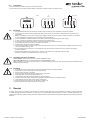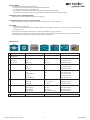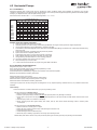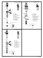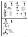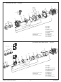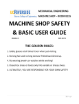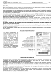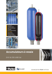
1
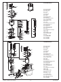
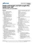
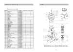
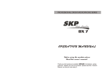
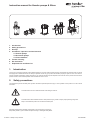
Instruction manual for Hendor pumps & filters
1.
2.
3.
4.
Introduction
Safety precautions
Receipt
Installation / Operation and maintenance
4.1 Vertical pumps
4.2 Horizontal pumps
4.3 Filter chambers
5. Trouble shooting
6. EC declaration
7. Exploded view and Parts list
1. Introduction
Thank you for choosing a Hendor product. Before starting to use this product Hendor strongly recommends to read this owner’s manual
thoroughly and to follow instructions as closely as possible. In this way your product will function properly for years to come. This owner’s
manual contains all obligatory safety precautions. The manual should be put at disposal of the end-user of this product and should be
present at site in order to allow operator and maintenance crew to use it.
2. Safety precautions
The presented symbols are safety alert symbols. Be alert to potential personal injury in case symbols on the product or in this manual
are shown.
This label warns for risk of electrical shock when failing to observe.
DANGER
!
This label warns about hazards that can cause personal injury, death or major property damage if ignored.
Keep in mind that the product can contain chemical liquids.
WARNING
Carefully read and follow all safety instructions in the manual and on the pump.
Keep safety labels in good condition. Replace missing or damaged safety labels.
© Hendor - Quality Pumps & Filters - 1 -
Info 28640/R0
2.1
Installation
Pumps and filters should be connected in the prescribed way.
The user always has to consider personal safety and health for himself as well as his direct vicinity.
3-phase
I
W2
U2
U1
L1
2.2
V1
L2
V2
W1
L3
single phase
r
W2
U1
L1
U2
V1
L2
V2
W1
N
L
L3
Electrical
1. Only qualified electricians are allowed to connect pumps according to local regulations of the power supplier.
2. Grounding of the motor should be applied first; failure to ground can cause severe or fatal shock. Do not ground to gas supply lines.
3. Before connecting the motor check corresponding voltage of motor and power supply. Incorrect connection can cause fire or serious damage to the motor and voids warranty. See wiring diagram.
4. Avoid unexpected or accidental starting of the motor by disconnecting and locking out power supply.
5. In case of repair and maintenance disconnect and lock out power supply.
6. Do not point a jet of water at the motor to avoid personal injury (risk of electrical shock).
7. Check wiring dimensions according to the power of the motor.
8. Check fuses on the power supply connection.
9. Thermal overload switch should be used on the connection to the pump. The current overload is adjusted to the value of the motor name plate including +10%.
10.Do avoid damage to the cord line by not hoisting the pump by the cord line and be sure the cord line is not jammed;
avoid sharp edges.
11.General rule for Hendor pump shaft rotation: Always run clockwise (CW), looking at cooling fan side.
Direction of rotation is also indicated on the motor by arrow.
!
!
2.3 Checking direction of rotation
Vertical pumps: Always check direction of rotation outside the liquid.
Horizontal pumps: Always check the direction of rotation flooded with liquid.
Briefly switching on the power will show direction of rotation, looking at cooling fan side. Ignoring these recommendations will
damage the pump severely.
2.4 Plumbing
1. Connections to the pump and filter should be provided with reliable, persistent materials.
2. Where hoses are used, take care of correct hose clamps.
3. Use the right O-rings for connections.
4. Pipes and hoses should be internally cleared of any obstructions.
5. Check tightness of connections before starting up.
6. Thermoplastic components will not tolerate any plumbing stress.
7. Plumbing should be properly aligned and supported to prevent distortion and damage of parts.
8. Leave enough space for easy access and/or maintenance.
9. Keep position of pump away from any heaters or heater coils.
10.Pumps and filters should be mounted on a sturdy base.
3. Receipt
At receipt of the product the identity of the product (by checking name plate data), the completeness of delivery as well as absence
of visible damage should be ascertained. The end-user or his representative must ascertain the match of material specification and
specific liquid used. Any problems arising from these checks should be made in writing and preferably signed by the forwarding agent as
evidence.
© Hendor - Quality Pumps & Filters - 2 -
Info 28640/R0
4.1 Vertical pumps
4.1.1 Installation
minimum bottom distance vertical pumps
120
100
D200
80
Distance in mm
Take notice of enough bottom clearance at the
suction side of vertical pumps.
See recommendations for bottom clearance.
Hendor vertical pumps are designed for
in-tank installation.
Out-of-tank models are optional and require
special installation instructions.
D170
60
D110 / D120
40
D90
20
0
0
15000
min.
Immersion
length
(mm)
max.
20000
25000
30000
35000
40000
45000
50000
55000
60000
Capacity in l/h
5
6
10000
B
A
1
2
3
4
5000
Suction
extension
1
2
3
4
5
maximum liquid level
normal working level minimal starting level
pump A stops pumping
pump B will continue to work
(provided it is not switched off intermittently)
6 pump B stops pumping
4.1.2 Operation and maintenance
These type of pumps are capable of running dry. At start up the pump should be checked for direction of rotation outside the liquid.
Contaminated strainers if mounted can reduce performance and should be cleaned regularly.
Regular pump inspection
During operation all pumps should be checked regularly. Check flow, pressure, manometer indication, pipe work, hoses, hose clamps
and absorbed power by monitoring amperage of the motor. Pumps should be fitted with thermal overload switch. Check pumps for any
unusual noise or vibration (this may indicate the moment of maintenance).
Maintenance precautions
To avoid dangerous or fatal electric shock hazard and to avoid injury from starting the motor unexpectedly, disconnect and lock
out power supply to the motor. Always use genuine parts to assure good performance. When taking pump apart check for
sequence of disassembly and reassembly. After having completed maintenance or repair, follow safety and installation
instructions.
4.1.3 Dismantling and reassembly
For efficient maintenance of Hendor vertical pumps, some special tools are available (see page 4).
!
General precautions prior to dismantling
-
always disconnect electric cables.
disconnect discharge pipe.
watch remaining liquid in pump housing.
do work on a clean bench.
When ordering Hendor parts always quote pump type and serial number.
Dismantling
-
-
-
-
-
-
-
remove drip cover (if applicable).
remove fan cover.
remove cooling fan by applying two screwdrivers.
remove sealing ring and locking ring.
turn pump upside down.
remove volute cover (by turning clockwise).
secure shaft end against rotation and loosen impeller (turning anti-clockwise) by using impeller key.
Series D90
-
-
-
-
take off wiring casing of motor by removing 3 bolts; mind not to damage stator wiring!
unscrew 4 screws that are accessible for removing pump house
take off pump house
loosen shaft protection pipe (turning anti-clockwise)
Other series
- remove bolts/nuts that connect motor to pump housing.
- take off pump housing completely.
- loosen impeller-shaft protection pipe (if applicable).
© Hendor - Quality Pumps & Filters - 3 -
Info 28640/R0
Electric Motor
All motors are fitted with standard ball bearings.
- by removing rear-end and front-end cover, bearings are accessible.
- rear bearing can be taken off by standard puller.
- front bearing is only accessible after taking out spring ring and removing front shield.
front bearing of vertical pump motors can only be taken off by applying special Hendor bearing puller.
Replacing worn or damaged parts
Dismounting and refitting should be carried out very carefully.
Assembling motor is done in reverse order
Ensure free rotation and check end play of the shaft of vertical pumps at 0,03 mm maximum.
Assembly
- refit all parts in reverse order.
- prior to mounting volute cover measure distance between top of impeller and bottom of volute cover; this dimension should be in range of 1-2 mm.
Prior to operation of the pump check direction of rotation as indicated by arrow on the motor.
Motor shaft rotation is clockwise, viewed from top of the motor. Testing the rotation of the shaft has to be done outside the liquid; running the pump backwards may loosen the impeller and damage the pump.
Special tools
Grip Impeller key Radius key Pen key Wrench Bearing puller Toolbit
Pump type
Article number
1 Suction extension pipe
For disassembly of
Wrench All types
9999-000-000-037
(if applicable)
Use
2 Strainer (if applicable)
Flat strainer
Grip
D17*
9011-000-001-499
High strainer
Radius key
All types
9062-600-999-002
D9*/D110/D12* 9011-000-001-551
9011-000-001-499
3 Pump house cover
Grip
Grip
D17*
Pen key
D2**
4 Impellor Grip
D9*/D110/D12* 9011-000-001-551
Grip
D17*
9011-000-001-499
and Impellor key
9011-891-001-080
Pen key
9063-623-100-250
and Impellor key
9011-891-001-080 Toolbit M4
0,12 - 0,18 - 0,25 kW
9999-000-000-020
Toolbit M5
0,37 .. 2,2 kW
9999-000-000-021
Toolbit M6
3 .. 9 kW
9999-000-000-047
5 Motor
D2*
9063-623-100-250 6 Motor bearings
Complete bearing puller set
All types
9999-000-000-031
Bearing puller
D9* only
9999-000-000-023
Bearing puller
D110 only
9999-000-000-024
Bearing puller
D12*/D170/D2* only
9999-000-000-025 PU Paint
0.25L tin (Hendor brown)
All motors
9999-000-000-041
© Hendor - Quality Pumps & Filters - 4 -
Info 28640/R0
4.2 Horizontal Pumps
4.2.1 Installation
Horizontal magnetic drive & seal pumps are very sensitive to suction conditions. Many pump problems are caused by poor suction
conditions. The bigger the pump and the higher the temperature, the more important the general hydraulic guidelines should be applied.
Always try to respect the basic rules for liquid velocity v (m/s).
We recommend for Suction side v = 1 - 2 m/s; Discharge side v = 1,5 - 3 m/s
Inner pipe diameter (mm)
Flow
l/h
15
20
1000
2000
4000
6000
8000
10000
15000
20000
30000
40000
1,57
3,15
6,29
0,88
1,77
3,54
5,31
25
32
40
50
65
Velocity (m/s) at given flow (l/h)
0,57
1,13 0,69
2,26 1,38 0,88
3,4 2,07 1,33
4,53 2,76 1,77 1,13
5,66 3,46 2,21 1,42 0,84
5,18 3,32 2,12 1,26
6,91 4,42 2,83 1,68
10,4 6,63 4,25 2,51
8,85 5,66 3,35
80
0,83
1,11
1,66
2,21
100
1,1
1,4
Golden rules for proper pipe work
1.
2.
3.
4.
5.
6.
7.
8.
9.
10.
11.
12.
Keep suction pipe work as short as possible.
Increase pipe size on suction side by at least one pipe diameter for longer suction pipe and/or higher temperature.
Use eccentric adaptors at varying diameters to prevent air pockets.
Avoid elbows, bends and fittings at suction side. When unavoidable keep fittings at a distance of 10 times pipe diameter away from pump inlet.
Pipe work should slope up towards pump to prevent air pockets.
Pipe work should be completely leak free.
Support pipe work near to pump to prevent stress on plumbing.
Allow sufficient liquid level to prevent air intake on suction side.
Use generously oversized strainer in case of foreign particles.
Use siphon breaker when priming over top of tank.
Never throttle pump on suction side.
In case of doubt consult Hendor for proper sizing and NPSH calculation.
4.2.2 Operation and maintenance
Magnetic drive pumps. How it works?
Driver (motor) and impeller (driven) are physically separated by a shell.
Pump part (wet end) is completely sealed.
Power transmission is established by magnetic force between motor shaft and impeller.
Bearings are lubricated and cooled by liquid itself.
Mechanical seal pumps. How it works?
Impeller is directly attached to the motor shaft by shaft coupling.
Mechanical seal on pump shaft prevents liquid from coming out.
Mechanical seal is lubricated and cooled by liquid itself.
These type of pumps are not self priming and not designed to run dry. Optional priming chambers and dry run protection devices are
available.
Initial start-up
1.Check for direction of rotation before start-up by shortly switching on/off.
Priming instructions at flooded suction:
2.Open all valves on suction and discharge side.
3.At start up the pump always should be flooded with liquid to prevent any damage on bearings.
4.These type of pumps are not self priming. Therefore liquid level in the bath should be ample above entrance level of the
pump.
5.Start the pump when no air remains in the pump.
6.When pumping liquid with higher density than water, start up with almost closed discharge valve to reduce power
consumption.
Priming instructions at non flooded suction:
2.Ensure entrance of suction pipe is in liquid.
3.Slowly fill pump casing and suction pipe. Use discharge connection to fill.
4.Check if pump is free of air.
5.Close discharge valve and start the pump.
6.Wait until pump is building up pressure, and slowly open discharge valve.
Restart after power failure: Check if the pump is able to prime again. Suction pipe and pump housing should be filled.
© Hendor - Quality Pumps & Filters - 5 -
Info 28640/R0
4.2.3 Dismantling and reassembly
!
4.2.3.1
Magnetic drive pumps
General precautions prior to dismantling
- always drain liquid from pump.
- disconnect all necessary electric cables or use switch on pump.
- disconnect suction and discharge piping (watch spilling liquid).
- do work on a clean bench.
When ordering Hendor parts always quote Pump Type and Serial Number.
Dismantling
- remove bolts from pump casing.
- take out impeller and impeller shell; mind strong magnetic force.
Replacing worn or damaged wet end parts
Series M10..M15
- rear static bearing is easy to replace.
- take ceramic shaft out of casing and replace it.
- rotating bushing is molded into impeller; replacing only possible by exchanging complete impeller.
Series MX60..MX120 and M110..M400
- static bearings cannot be replaced (heat shrinked); when damaged replace complete part.
- rotating bearings are mounted by thread; front right-handed thread ; rear left-handed thread.
General description of dismounting a drive magnet
- loosen hex. screws through hole in bracket.
- by means of a lever drive magnet down the shaft; mind strong magnetic force.
- check for remaining metal particles on the magnet and remove them.
General description of mounting a drive magnet
-
-
-
-
slightly grease shaft of motor.
replace drive magnet on shaft by hand watching position of key.
ensure that drive magnet goes up to shaft end (when using a hammer, be sure motor bearings are not damaged).
secure hex. screws.
Assembly
-
-
-
-
mount impeller shell.
put impeller into shell; mind strong magnetic force.
place O-ring and put pump casing into place.
mount bolts and tighten them crosswise.
After assembly always check for free rotation by hand. Verify direction of rotation indicated by arrow on pump/motor prior to regularoperation.
4.2.3.2
Mechanical seal pumps S55 .. S300-PP
General precautions prior to dismantling
- always drain liquid from pump.
- disconnect electric cables or use switch on pump.
- disconnect suction and discharge piping.
- do work on a clean bench.
!
When ordering Hendor parts always quote pump type and serial number.
Dismantling
-
-
-
-
-
remove bolts from pump casing.
take off SS plate and pump casing.
turn safety guard so that hex. screw on coupling is accessible.
loosen front screw in coupling (pump side).
take out impeller together with rotating parts of mechanical seal.
Replacing worn or damaged parts
- rear static seal ring is easy to replace; mind position of seal ring according to locking pin; always renew O-rings after removing parts.
- take off rotating part; mind position of coil and hook; at replacing seal ring do position O-ring, coil and hook.
© Hendor - Quality Pumps & Filters - 6 -
Info 28640/R0
Assembly
-
-
-
-
-
-
-
-
-
put back cover including static seal ring in place against steel bracket; mind upright position of supply channel for seal.
place flat rubber gasket in position.
put a spacer (thickness 2 mm) between back cover and steel bracket (adjusting pre-load on seal).
put impeller back into position; mind correct position of all rotating parts.
push impeller firmly as far as possible; hold that position and secure front hex. screw in coupling.
remove spacer from back cover.
put pump casing and SS plate back into place.
mount bolts and tighten them gradually.
turn safety guard so that holes are pointing downwards (drain in case of leakage).
Check for free rotation by turning cooling fan by hand.
Prior to operation of the pump check direction of rotation as indicated by arrow on the motor.
Testing the rotation has to be done flooded with liquid.
© Hendor - Quality Pumps & Filters - 7 -
Info 28640/R0
4.3 Filter chambers
4.3.1 Installation
Following rules should be respected when installing filter chambers:
Bottom of filter chamber (by preference) is placed at the same height as bath level; this will ensure an easy medium change and prevents
unwanted emptying of tank.
1. Maximum pressure should not exceed indication on dial of manometer.
2. Maximum allowable pressure at temperature range is indicated on top of filter chamber.
3. Adjust diameter of in- and outlet of the filter to required capacity of the system.
4. Return pipe from filter chamber should be placed as far as possible from pump inlet in order to promote good bath movement.
5. Filter chamber 362 has a tiltable lid. Position of lid can be changed by positioning top ring (304).
4.3.2 Operation and Maintenance
Maximum pressure in filter chamber
The maximum pressure in Hendor filter chamber should not exceed the engraved value on top of the cover plate.
Pressure gauge
A pressure gauge is fitted on most Hendor filter chambers. An anti-freeze filled chamber above a membrane separates the pressure gauge
from the process liquid. During normal operation the filter chamber regularly should be inspected for flow (dial indication on gauge).
If pressure on manometer is less than usual, the chamber below the manometer should be refilled.
Topping up manometer liquid:
After removing gauge (328) and air release screw, top up casing (327) with anti-freeze.
When assembling gauge (mind O-ring 335) liquid must show up.
Put back air release screw into casing and tighten it.
If liquid does not show up repeat procedure here above. If still no liquid shows up the membrane should be replaced.
Remove gauge (328), unscrew 4 screws, take off the lid (327), replace membrane (326), refit 4 screws lightly, holding down the membrane
with unsharp object through lid, tighten 4 screws and repeat above mentioned procedure.
If pressure on the dial of the gauge is not coming back to zero, when the pump is switched off, there may exist a difference of
pressure between inside gauge and open air. To correct dial indication cut off the top of the rubber cap on top of the gauge.
4.3.3 Dismantling and reassembly
Replacement of filter elements
Depending on the type of filter, the filter element(s) should be exchanged reaching a maximum pressure difference of 1-2,5 bar.
Sequence of operation
-
-
-
-
-
-
switch off pump (ensure pump cannot be started unexpectedly).
close all main taps.
open drain valve.
open air release tap to empty filter chamber.
loosen all star buttons.
remove or tilt the lid of the filter chamber; sometimes the gasket sticks to the chamber and extra lifting effort is required to remove the lid.
Hendor filter chambers are equipped with cartridges, discs or bags.
After removing the contaminated filter medium it should be disposed off according to environmental guidelines.
Properly install the new filter medium to prevent by-pass of unfiltrated liquid.
Closing sequence
-
-
-
-
-
-
-
check sealing rubber of chamber on distortion.
close lid
turn two fixed star button 4 times clockwise.
tighten remaining star buttons firmly crosswise.
close drain valve, open main taps and start-up the pump.
check unit for any leakage.
after bleeding the unit, close air release tap.
© Hendor - Quality Pumps & Filters - 8 -
Info 28640/R0
5. Trouble shooting
Pump problem
Possible reason - horizontal pump
Possible reason - vertical pump
No liquid flow
Insufficient liquid flow
Insufficient pressure
Rising liquid temperature
Noisy pump or excessive vibration
Motor is overheating
Motor overload activated
Cracking/deformation
Corrosion
2-3-4-5-6-7-8-12-15-22-24-31
1-3-6-8-10-11-13-14-15-16-18-19-20-25-28-29
8-10-13-14-15-16-18-20-25-29-30
8-15-19-25
1-3-6-13-14-15-20-21-22-23-28-34
13-15-16-20-21-22-23-24-25-27-28-29-30
20-25-26-28-29-30
9-34-49
27-50
4-5-7-8-12-15-17-22-24-28-31
8-10-13-14-15-16-18-19-20-25-28-29-30
10-13-14-16-18-30-25-29-30
8-15-18-19
9-13-14-15-16-17-21-22-23-32
15-16-21-22-23-24-25-27
22-25-26-29-30
9-34-49
27-50
Filter problem
No or insufficient liquid flow
Leakage
Pressure gauge reading not correct
High dial indication on pressure gauge
Bad filtering result
Foam formation in the bath
Possible reason
8-19-28-38-39-41-42-48
39-40-49
35-36-37-38
8-42-48
33-42-43-45-47
11-31-46
System / Pipework
1 Suction pipe too long or diameter too small
2 Air pocket in suction pipe
3 Leak in suction pipe
4 Suction pipe or strainer blocked
5 Suction height too high
6 Air supply close to suction inlet
7 Foot valve or suction pipe insufficiently submerged
8 Valve in pipework (partly) closed
9 Discharge pipe under tension
10Leak in discharge pipe
11Return pipe not submerged (air intake)
12Liquid level in tank too low
Liquid
28Liquid has crystallised
29Specific gravity of liquid too high
30Viscosity of liquid too high
31Air / gas in liquid
32Abrasive particles in liquid
33Colloïdal liquid
34Liquid temperature too high
Pump
13Impeller damaged or worn out by abrasives
14Impeller out of balance
15Impeller / volute blocked by foreign matter
16Wrong impeller choice (50 or 60 Hz)
17Volute not immerged sufficiently in the liquid
18Wrong choice of pump size
19Pump is running at very low flow
Motor
20Wrong direction of rotation
21Cooling fan blocked or loose
22Motor bearings jammed or worn out
23Motor bearings incorrectly installed
24Motor down on a phase
25Incorrect voltage
26Thermal overload setting incorrect
27Insufficient cleaning
Filter
35Not enough anti-freeze in chamber below pressure gauge
36Membrane in chamber below pressure gauge deformed/damaged
37Pressure gauge defect
38Filter chamber insufficiently bled
39Filter chamber not closed properly
40Filter chamber gasket damaged of deformed
41Filter element incorrectly installed
42Filter system element saturated
43Bypass of unfiltrated liquid
44Filter medium is too coarse
45Filter material damaged or torn
46Unwashed cartridges used (residues of wetting agents)
47Wrong choice of filter medium
48Wrong choice of micron rating
Material / Environment
49Wrong choice of pump / o-ring material
50Aggressive environment
© Hendor - Quality Pumps & Filters - 9 -
Info 28640/R0
6.
EC-Declaration of conformity Manufacturer:
Address:
Hendor Pompen BV
P.O. box 9
5530 AA Bladel
The Netherlands
Herewith we declare, that the product:
Pump
-
is in conformity with the provisions of the Machinery Directive, as amended, and with national
implementing legislation (Directive 98/37/EC, annex II sub A)
-
is in conformity with the provisions of the following other EC directives: Low voltage directive (Directive 73/23/EC)
Filter
Confirmed at Bladel
Signature
Technical Director H.F.G. Bohncke
-
is in conformity with the provisions of the Pressure Equipment Directive PED97/23/EC
© Hendor - Quality Pumps & Filters - 10 -
Info 28640/R0
Series D90 - PP/PVDF
218
Series D110 - PP
218
211
211
224
209
option
206
704
703
201
202
204
207
211
212
213
218
224
703
704
201
207
207
Volute
Volute cover
Impeller
Shaft protection pipe
Electric motor
O-ring
Suction extension pipe
Motor drip cover
Splash guard
Connection
Connection
216
201
208
204
204
201
202
203
204
206
207
208
209
211
213
216
218
Volute
Volute cover
Strainer
Impeller
Discharge pipe
Shaft protection pipe
Discharge elbow
Mounting plate
Electric motor
Suction extension pipe
Fastener kit
Motor drip cover
202
option: with suction extension pipe
203
option: with suction extension pipe
212
202
202
213
213
Series D120 - PP/PVDF
218
211
216
207
704
703
201
204
202
201
202
204
207
211
212
213
216
218
703
704
Volute
Volute cover
Impeller
Shaft protection pipe
Electric motor
O-ring
Suction extension pipe
Fastener kit
Motor drip cover
Connection
Connection
option: with suction extension pipe
212
213
© Hendor - Quality Pumps & Filters - 11 -
Info 28640/R0
Series D160 - SS316
Series D170 - PP/PVDF
218
218
211
216
211
216
209
201
215
204
209
222
223
204
205
212
201
219
206
201
204
205
209
211
212
215
216
218
219
222
223
Volute
Impeller
Impeller screw
Mounting plate
Electric motor
O-ring
Bracket
Fastener kit
Motor drip cover
Fixation set
V-ring
Bearing
201
202
203
204
206
209
211
212
213
216
218
220
221
Volute
Volute cover
Strainer
Impeller
Discharge pipe
Mounting plate
Electric motor
O-ring
Suction extension pipe
Fastener kit
Motor drip cover
Union nut
O-ring
reinforced
economy
212
202
202
203
203
202
221
203
213
213
220
Series D200 - PP
211
216
219
209
201
206
204
202
203
201
202
203
204
208 206
208
209
211
213
216
219
Volute
Volute cover
Strainer
Impeller
Discharge pipe
Discharge elbow
Mounting plate
Electric motor
Suction extension pipe
Fastener kit
Fastener kit
213
© Hendor - Quality Pumps & Filters - 12 -
Info 28640/R0
Series M10 - M11 - M15 - PP/PVDF
F on
PVD
ly
111
115
117
703
113
out
114
105
104
106
101
703in
C
100
B
100
A
101
104
105
106
111
113
114
115
117
119
175
703
100
119
100A Pump without motor
100B Wet end
100C Impeller complete
Volute
Impeller
O-ring
Shaft
Electric motor
O-ring (PVDF only)
Impeller housing
Bracket
Drive magnet
Fastener kit
O-ring kit (all O-rings)
Connection
Series MX40 - MX60 - MX90 - MX120 - PP/PVDF
MX120 only
707out
111
707in
115
117
114
105
108
703out
104
107
101
703in
C
100
B
100
A
100
119
100A Pump without motor
100B Wet end
100C Impeller complete
© Hendor - Quality Pumps & Filters 101
104
105
107
108
111
114
115
117
119
175
703
707
Volute
Impeller
O-ring
Impeller front bearing
Impeller rear bearing
Electric motor
Impeller housing
Bracket
Drive magnet
Fastener kit
O-ring kit (all O-rings)
Connection
Connection (MX120)
- 13 -
Info 28640/R0
Series M110 - M150 - M220 - M300 - M400 - PP/PVDF
W
3-4k
Only
111
xcl.
WE
1.1k
115
117
114
105
703out
108
104
107
101
703in
C
100
B
100
A
100
119
100A Pump without motor
100B Wet end
100C Impeller complete
101
104
105
107
108
111
114
115
117
119
175
703
Volute
Impeller
O-ring
Impeller front bearing
Impeller rear bearing
Electric motor
Impeller housing
Bracket
Drive magnet
Fastener kit
O-ring kit (all O-rings)
Connection
Series S55 - S75 - S110 - S150 - S220 - S300 - PP
111
125
126
103
124
110
703out
121
122 105
105
123
109
104
120
101
102
703in
C
100
B
100
A
100
119
© Hendor - Quality Pumps & Filters 100A
100B
100C
101
102
103
104
105
109
110
Pump without motor
Wet end
Impeller complete
Volute
SS plate
Bracket
Impeller
O-ring
Rotary seat
Stationary seat
111
119
120
121
122
123
124
125
126
175
703
Electric motor
Fastener kit
Fastener kit
Spring
Driver
Gasket
Volute cover
Shaft coupling
Safety guard
O-ring kit (all O-rings)
Connection
- 14 -
Info 28640/R0
11/12-K-PP
F-11/12A-K-PP
329
329
321
321
320
320
403
403
403
403
401
401
401
401
402
402
401
302
361
310
339
703in
301
314
702
701
703out
401
302
301
302
310
314
320
321
329
339
361
375
401
402
403
701
702
703
Mounting plate
Filter housing
O-ring
Fastener kit
Gasket
Cover
Air release valve
O-ring
Seal plug
O-ring kit (all O-rings)
Support rod
Extension bushing
Knob support rod
Connection
Connection
Connection
302
305
310
314
320
321
329
329
310
339
305
314
701
702
704
339
375
401
402
403
701
702
704
Filter housing
Chassis
O-ring
Fastener kit
Gasket
Cover
Air release valve
or drain valve
O-ring
O-ring kit (all O-rings)
Support rod
Extension bushing
Knob support rod
Connection
Connection
Connection
21/22-K-PP
329
321
403
320
403
401
401
402
401
302
361
361
310
339
600
305
314
705
701
© Hendor - Quality Pumps & Filters 302
305
310
314
320
321
329
339
361
375
401
402
403
600
701
705
Filter housing
Chassis
O-ring
Fastener kit
Gasket
Cover
Air release valve
O-ring
Seal plug
O-ring kit (all O-rings)
Support rod
Extension bushing
Knob support rod
Pipe work discharge
Connection
Pipe work
- 15 -
Info 28640/R0
F-31/32A-K/P-PP
350
328
335
327
326
325
329
334
321
320
319
317
304
403
411
403
410
302
409
400
303
408
701
702
401
401
405
402
407
406
301
405
404
404
401
703in
703out
403
301
302
303
304
317
319
320
321
325
326
327
328
329
334
335
350
375
400
401
402
403
404
405
406
407
408
409
410
411
701
702
703
Mounting plate
Filter housing
Bottom ring
Top ring
Rod
Star knob
Gasket
Cover
Gauge housing
Membrane
Cover gauge housing
Pressure gauge
Air release valve
O-ring
O-ring
Assembly pressure gauge
O-ring kit (all O-rings)
Filter element
Support rod
Extension bushing
Knob support rod
O-ring
Baseplate disc/cartridge
O-ring
Base disc holder
Rod disc holder
Disc
Top disc holder
Nut disc holder
Connection
Connection
Connection
31/32A-K/P-S-PP
403
350
328
329
321
405
402
335
334
401
401
327
326
325
404
320
319
317
401
304
411
302
410
400
409
303
408
407
406
702
701
340
405
404
500
305
600
© Hendor - Quality Pumps & Filters 302
303
304
305
317
319
320
321
325
326
327
328
329
334
335
340
350
375
400
401
402
403
404
405
406
407
408
409
410
411
500
600
701
702
Filter housing
Bottom ring
Top ring
Chassis
Rod
Star knob
Gasket
Cover
Gauge housing
Membrane
Cover gauge housing
Pressure gauge
Air release valve
O-ring
O-ring
Slurry tank
Assembly pressure gauge
O-ring kit (all O-rings)
Filter element
Support rod
Extension bushing
Knob support rod
O-ring
Baseplate disc/cartridge
O-ring
Base disc holder
Rod disc holder
Disc
Top disc holder
Nut disc holder
Pipe work suction
Pipe work discharge
Connection
Connection
- 16 -
Info 28640/R0
F-71/72A-K/P-PP
350
328
335
327
326
325
329
334
301 Mounting plate
302 Filter housing
303 Bottom ring
304 Top ring
317 Rod
319 Star knob
320 Gasket
321 Cover
325 Gauge housing
326 Membrane
327 Cover gauge housing
328 Pressure gauge
329 Air release valve
334 O-ring
335 O-ring
350 Assembly pressure gauge
375 O-ring kit (all O-rings)
400 Filter element
401 Support rod
402 Extension bushing
403 Knob support rod
404 O-ring
405 Baseplate disc/cartridge
406A O-ring
406B O-ring
407 Base disc holder
408 Rod disc holder
409 Disc
410 Top disc holder
411 Nut disc holder
701 Connection
702 Connection
703 Connection
321
320
319
304
317
403
411
403
410
302
409
400
303
408
406A
406B
301
405
402
405
404
401
404
703in
703out
401
407
701
702
401
71/72A-K/P-S-PP
403
403
350
328
401
335
327
326
325
329
334
401
402
405
321
401
404
320
319
304
317
411
410
302
400
409
303
408
407
406A
406B
702
701
340
405
404
500
305
600
© Hendor - Quality Pumps & Filters 302 Filter housing
303 Bottom ring
304 Top ring
305 Chassis
317 Rod
319 Star knob
320 Gasket
321 Cover
325 Gauge housing
326 Membrane
327 Cover gauge housing
328 Pressure gauge
329 Air release valve
334 O-ring
335 O-ring
340 Slurry tank
350 Assembly pressure gauge
375 O-ring kit (all O-rings)
400 Filter element
401 Support rod
402 Extension bushing
403 Knob support rod
404 O-ring
405 Baseplate disc/cartridge
406A O-ring
406B O-ring
407 Base disc holder
408 Rod disc holder
409 Disc
410 Top disc holder
411 Nut disc holder
500 Pipe work suction
600 Pipe work discharge
701 Connection
702 Connection
- 17 -
Info 28640/R0
F-71/72A-B-PP
350
328
327
326
325
334
335
329
321
320
319
304
317
302
414
413
303
702
701
301
302
303
304
317
319
320
321
325
326
327
328
329
334
335
350
375
404
412
413
414
701
702
703
Mounting plate
Filter housing
Bottom ring
Top ring
Rod
Star knob
Gasket
Cover
Gauge housing
Membrane
Cover gauge housing
Pressure gauge
Air release valve
O-ring
O-ring
Assembly pressure gauge
O-ring kit (all O-rings)
O-ring
Inner cylinder
Basket
Sealing
Connection
Connection
Connection
301
412
703out
703in
404
© Hendor - Quality Pumps & Filters - 18 -
Info 28640/R0
F-151/152A-K/P-PP
350
328
335
327
326
325
329
334
301 Mounting plate
302 Filter housing
303 Bottom ring
304 Top ring
317 Rod
319 Star knob
320 Gasket
321 Cover
325 Gauge housing
326 Membrane
327 Cover gauge housing
328 Pressure gauge
329 Air release valve
334 O-ring
335 O-ring
350 Assembly pressure gauge
375 O-ring kit (all O-rings)
400 Filter element
401 Support rod
402 Extension bushing
403 Knob support rod
404 O-ring
405 Baseplate disc/cartridge
406A O-ring
406B O-ring
407 Base disc holder
408 Rod disc holder
409 Disc
410 Top disc holder
411 Nut disc holder
701 Connection
702 Connection
703 Connection
321
319
320
317
304
403
411
302
403
410
400
409
401
303
401
408
405
702
407
301
402
404
401
406A
406B
701
703in
703out
405
404
151/152A-K/P-S-PP
403
403
350
328
335
327
326
325
334
401
401
329
321
319
402
405
401
320
404
317
304
411
410
302
400
409
303
408
407
406A
406B
702
701
340
405
404
305
500
600
© Hendor - Quality Pumps & Filters 302 Filter housing
303 Bottom ring
304 Top ring
305 Chassis
317 Rod
319 Star knob
320 Gasket
321 Cover
325 Gauge housing
326 Membrane
327 Cover gauge housing
328 Pressure gauge
329 Air release valve
334 O-ring
335 O-ring
340 Slurry tank
350 Assembly pressure gauge
375 O-ring kit (all O-rings)
400 Filter element
401 Support rod
402 Extension bushing
403 Knob support rod
404 O-ring
405 Baseplate disc/cartridge
406A O-ring
406B O-ring
407 Base disc holder
408 Rod disc holder
409 Disc
410 Top disc holder
411 Nut disc holder
500 Pipe work suction
600 Pipe work discharge
701 Connection
702 Connection
- 19 -
Info 28640/R0
350
328
327
326
325
334
F-362A-K/P-PP
335
329
302
303
304
306
317
319
320
321
322
323
324
325
326
327
328
329
331
334
335
350
375
400
401
402
403
404
405
409
410
415
416
600
701
702
703
322
323
321
320
319
331
317
304
403
410
400
302
409
303
415
2
401
416
702
402
401
405
404
306
600
405
404
701
703
350
324
328
327
326
325
334
362A-K/P-S-PP
335
329
322
323
321
320
319
331
317
304
410
302
403
400
340
409
303
415
2
702
401
416
402
701
405
404
306
703
401
405
404
600
324
Filter housing
Bottom ring
Top ring
Pedestal
Rod
Star knob
Gasket
Cover
Tilt stop
Handle
Wheel set
Gauge housing
Membrane
Cover gauge housing
Pressure gauge
Air release valve
Tilting set
O-ring
O-ring
Assembly pressure gauge
O-ring kit (all O-rings)
Filter element
Support rod
Extension bushing
Knob support rod
O-ring
Baseplate disc/cartridge
Disc
Top disc holder
Crown
Sealing plate
Pipework discharge
Connection
Connection
Connection
500
© Hendor - Quality Pumps & Filters 302
303
304
306
317
319
320
321
322
323
324
325
326
327
328
329
331
334
335
340
350
375
400
401
402
403
404
405
409
410
415
416
500
600
701
702
703
Filter housing
Bottom ring
Top ring
Chassis
Rod
Star knob
Gasket
Cover
Tilt stop
Handle
Wheel set
Gauge housing
Membrane
Cover gauge housing
Pressure gauge
Air release valve
Tilting set
O-ring
O-ring
Slurry tank
Assembly pressure gauge
O-ring kit (all O-rings)
Filter element
Support rod
Extension bushing
Knob support rod
O-ring
Baseplate disc/cartridge
Disc
Top disc holder
Crown
Sealing plate
Pipework suction
Pipework discharge
Connection
Connection
Connection
- 20 -
Info 28640/R0