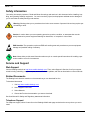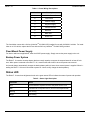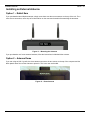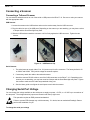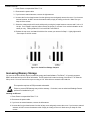
1
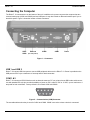
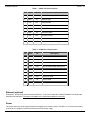
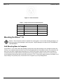
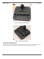
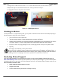
Rhino TM 10 Installation Manual Datalogic Mobile S.r.l. Via S. Vitalino 13 40012 - Lippo di Calderara di Reno Bologna - Italy Rhino™10 User's Manual Software Version: 1.0.x Part Number: 822001150 Ed.: 12/2011 Datalogic Mobile, Inc. Eugene, OR 97405 U.S.A. http://www.mobile.datalogic.com © 2011 Datalogic Mobile, Inc. • All rights reserved. • Protected to the fullest extent under U.S. and international laws. • Copying or altering of this document is prohibited without express written consent from Datalogic Mobile, Inc. Datalogic and the Datalogic logo are registered trademarks of Datalogic S.p.A. in many countries including the U.S.A. and the E.U. • Rhino is a trademark of Datalogic Mobile S.r.l. Other brands and product names may be trademarks of their respective owners. • Reasonable measures were taken to ensure that the information provided is complete and accurate at the time of publication. • Datalogic Mobile, Inc. is not responsible for errors of omission or inaccuracies, as material becomes dated shortly following publication. However, Datalogic reserves the right to change any product specification at any time without prior notice. The information contained herein is provided solely for the purpose of allowing customers to install, operate, configure, and develop applications for Datalogic manufactured equipment and is not to be released, reproduced, or used for any other purpose without written permission of Datalogic Mobile, Inc. The Bluetooth® word mark and logos are owned by Bluetooth SIG, Inc. and any use of such marks by Datalogic Mobile, Inc. is under license. Wi-Fi is a registered certification mark of the Wi-Fi Alliance. Microsoft, WindowsCE, and the WindowsCE logo are registered trademarks of Microsoft Corporation in the United States and/or other countries. Contents Safety Information .......................................................................................................................................................1 Service and Support ...................................................................................................................................................1 Web Support...........................................................................................................................................................1 Related Documents ................................................................................................................................................1 Telephone Support.............................................................................................................................................1 Introduction .................................................................................................................................................................2 Packing List.................................................................................................................................................................2 Rhino™ 10 Unit ......................................................................................................................................................2 Mount (optional)......................................................................................................................................................2 Keyboard (optional) ................................................................................................................................................2 Keyboard Mount (optional) .....................................................................................................................................2 Connecting the Computer ...........................................................................................................................................3 USB 1 and USB 2...............................................................................................................................................3 COM 1 & 2..........................................................................................................................................................3 Ethernet (optional)..............................................................................................................................................4 Power .................................................................................................................................................................4 Mounting the Rhino™ 10 ............................................................................................................................................5 Add Mounting Base to Computer ...........................................................................................................................5 Assemble the Mounting Arm ..................................................................................................................................6 Attach the Rail Base to the Vehicle....................................................................................................................7 Mount the Computer to the Vehicle ........................................................................................................................8 Mounting the Keyboard ..........................................................................................................................................8 Attaching the Rhino™ 10 to Power...........................................................................................................................10 Vehicle Connection...............................................................................................................................................10 Fixed Mount Power Supply...................................................................................................................................11 Backup Power System..........................................................................................................................................11 Status LED ................................................................................................................................................................11 Installing an External Antenna ..................................................................................................................................12 Option 1 – Rabbit Ears .........................................................................................................................................12 Option 2 – Antenna Dome ....................................................................................................................................12 Connecting a Scanner ..............................................................................................................................................13 Connecting a Tethered Scanner ......................................................................................................................13 Changing Serial Port Voltage....................................................................................................................................13 Increasing Memory Storage......................................................................................................................................14 Cleaning the Screen .................................................................................................................................................15 Contacting Product Support......................................................................................................................................15 < page intentionally left blank> Rhino™ 10 Installation Manual Safety Information Your safety is extremely important. Read and follow all warnings and cautions in this document before installing, handling, and operating Datalogic equipment. You can be seriously injured, and equipment and data can be damaged if you do not follow the safety warnings and cautions. Warning: Warnings alert you to procedures that involve some amount of personal risk and may require special training or tools. Caution: A caution alerts you to an operating procedure, practice, condition, or statement that must be strictly observed to prevent equipment damage or destruction, or corruption or loss of data. ESD Sensitive: The operation requires an ESD safe working area and procedures to prevent equipment damage and possible voiding of warranty. Note: Notes either provide extra information about a topic or contain special instructions for handling a particular condition or set of circumstances. Service and Support Web Support Visit the Datalogic web site at http://www.mobile.datalogic.com. Then, select Support & Services for all your support needs including submitting a support request, access to software updates, and links to download our current manuals. Related Documents The Datalogic web site also contains our documents that you can download for free. To download documents 1. Visit http://www.mobile.datalogic.com. 2. Select Support & Services. 3. Select Manuals. 4. Choose the Product documentation you want to download. See User Manual for Safety and Regulatory statements information. Telephone Support For telephone support, select Contact Us on the Datalogic Mobile web page and select the country where you are located. 1 Installation Manual Rhino™ 10 Introduction Before you begin to install and connect your new computer, take a few minutes to verify that everything you ordered is included in your shipment and that you have the necessary tools to complete the installation. Packing List Rhino™ 10 Unit Rhino™ 10 Power Cable Length = 13’ (4m) Bag - (4) #1/4-20 x ½” screws and nylon lock nuts and (4) washers. Bag - fuse holder, /2A fuse, 5A fuse, 3 each (3) 3/8”, (2) ¼”, (2) #10 crimp ring terminals, one crimp splice Bag - USB cable retainer and (2) #4-40x¼” screws External antennas (2) (Optional) Mount (optional) 75mm mount with 2.25” ball 7” arm Base, many optional types and sizes Keyboard (optional) Keyboard Keyboard Mount (optional) Box containing: 2 (2) flanged mounting plates (2) mount side arms Bag - (12) #8-32 x ½” screws and lock washers Rhino™ 10 Installation Manual Connecting the Computer The Rhino™ 10 connectors are on the bottom of the unit. In addition to the power connector the computer has two communication ports (COM1 and COM2) and two USB ports. It may also include an Ethernet interface port if you ordered this option. Figure 1 shows the location of these connectors. USB1 USB2 Ethernet COM2 COM1 Power (Ext. temp ONLY) Figure 1 – Connectors USB 1 and USB 2 Rhino™ 10 has two USB Host ports to connect USB peripheral devices to the Rhino™ 10. Power is provided on the USB ports at 5VDC up to a maximum of one amp total for both connectors. COM 1 & 2 Rhino™ 10 connects to RS-232 devices such as barcode scanners, PC’s or printers via two DB-9 male serial connectors with standard PC style pin-out with the addition of power on Pin 9, either 5 VDC or 12 VDC, up to a maximum or 1 amp total for both connectors. Factory default is 5V on both COM1 and COM2. 1 2 6 3 7 4 8 5 9 Figure 2 – Communication (COM) Connector The two tables below show the pin-outs for COM1 and COM2. COM2 is not active unless a device is connected. 3 Installation Manual Rhino™ 10 Table 1 – COM1 Pin-Out Description Pin Name Dir Description 1 CD IN Carrier Detect 2 RXD IN Receive Data 3 TXD OUT Transmit Data 4 DTR OUT Data Terminal Ready 5 GND ------ System Ground 6 DSR IN Data Set Ready 7 RTS OUT Request to Send 8 CTS IN 9 SPWR OUT Clear to Send Power (None, +5V, +12V @ 1A max) Table 2 – COM2 Pin-out Description Pin Name Dir Description 1 CD 2 RXD IN Receive Data 3 TXD OUT Transmit Data 4 DTR OUT Data Terminal Ready (always true) 5 GND ------ System Ground 6 DSR 7 RTS OUT 8 CTS IN 9 SPWR OUT Not connected Not connected Request to Send Clear to Send Power (None, +5V, +12V @ 1A max) Ethernet (optional) When active, the Ethernet connector allows the Rhino™ 10 to communicate with 10BaseT/100BaseT full duplex standard Ethernet interfaces. This feature is available on the entended temperature model only. Power The power connector can be used to attach the computer to the vehicle’s power. The Rhino™ 10 can be connected to a variety of DC voltages (10-60VDC) as well as an AC/DC power supply. 4 Rhino™ 10 Installation Manual Figure 3 – Power Connector Table 3 – Power Connector Pin-Out Description Pin # Function Cable Color 1 Chassis Ground Brown 2 Not connected N/A 3 + Power, 10-60V Blue 4 Ground Black Mounting the Rhino™ 10 Caution: The touch panel consists of a plastic film covering glass. Use care when handling the Rhino™ 10 during mounting to avoid damage to the touch panel. Physical damage to the panel is NOT COVERED BY THE WARRANTY. Add Mounting Base to Computer Lay the Rhino™ 10 on a flat surface with padding to protect the touch panel (the bag the unit is shipped in works well for this). If you ordered a keyboard mount, lay one of the flanged plates from the keyboard mount over the studs on the back of the unit with the flanges bent towards the unit. The ball on the base is offset from the center of the base so consider which way the offset should be arranged for the mounting distance needed. Use the four 1/4-20 nylon lock nuts and washers included with the unit and using a wrench or 7/16” (11mm) socket tighten securely (if available, use a torque setting of 5 ft pounds (6 Nm). Be careful not to over-tighten or you may damage studs. 5 Installation Manual Rhino™ 10 Figure 4 – Base without Keyboard Mount Figure 5 – Base with Keyboard Mount Assemble the Mounting Arm The mounting arm may come unassembled. Put the parts together as shown in Figure 6 and tighten the nut 2-3 turns. Then, place the arm on the ball of the base with the spring side of the arm farthest away from to the unit. 6 Rhino™ 10 Installation Manual Figure 6 – Unassembled Mounting Arm Figure 7 – Assembled Mounting Arm Attach the Rail Base to the Vehicle There are two different bases available from Datalogic, the Ram 4” Rail Base (P/N 94ACC0035) and the Ram Mount with Round Base (P/N 94ACC0034). This section describes the use of the standard rail mount base. Other bases will require different mounting techniques. Select the location on the vehicle for the mount base. For the rail base, insert one screw through the two base parts and turn on the lock nut finger tight. Hold the base up to the post or rail selected, and insert the second bolt through the base. Swing the back plate around and over the bolt. Turn the second lock nut on finger tight. Tighten the bolts with a 3/16” hex driver (not included). Figure 8 – Mounting Base Assembly 7 Installation Manual Rhino™ 10 Mount the Computer to the Vehicle Hold the computer by the junction of the Ram mount arm and the base on the back of the unit. Lift the assembly to the base on the vehicle. Open the arm until the end slides over the ball on that base. Tighten the wing nut firmly. Once the computer is attached, it can adjusted by holding the bottom of the computer, loosening the wing nut on the arm by one turn moving the Rhino™ 10 to the desired position and re-tightening the wing nut on the arm. ALWAYS hold the Rhino™ 10 before loosening the arm. Failure to hold the Rhino™ 10 can cause it to swing down suddenly and may cause injury or damage the unit! Mounting the Keyboard The Keyboard Mounting Kit includes: Side supports (2) 2 interchangeable side supports 2 interchangeable mounting plates 12 8-32 machine screws with lock washers Tools required: Mounting plates (2) #2 Phillips screwdriver (not included) Prior to beginning this procedure you should have already attached the mounting base and mounting ball to the computer as described in Adding Mounting Base to Computer above. 1. Attach the long end of the two side supports to the mounting base on the Rhino™ 10 using four of the 8-32 screws and lock washers. 2. Attach the second flanged plate to the short end of the sides with the flanges down using the four 8-32 screws and lock washers. Note that the screw holes in the center of the mounting plate are closer to one side of the mounting plate. These holes should be place closest to the computer so that, when the keyboard is attached, it will be fully supported by the mounting plate. This is shown in the picture to the left. 8 Rhino™ 10 Installation Manual 3. Align the keyboard with the offset holes mentioned in the previous step and attach the keyboard to the mounting plate using the four remaining 8-32 screws and lock washers. 4. Plug the USB cable into the top USB port on the Rhino™ 10. A B C 5. As shown in A+B, install the USB retainer on the underside of the Rhino™ 10 and loosely insert the two ¼”-32 screws provided. C – Slide the USB cable into the slot in the USB cable retainer. Position the cable retainer so that the USB connector is held firmly in place and tighten the two screws. 6. Secure the keyboard cable under the keyboard mount using the 2 wire ties provided. Figure 9 – Mounting the Keyboard 9 Installation Manual Rhino™ 10 Attaching the Rhino™ 10 to Power For the Rhino™ 10 to operate, you must provide power from the vehicle DC power supply (12V – 60V) or from an AC/DC power supply. Positive power should go to a non-switched connection, so the unit retains power even when the vehicle is off. Vehicle Connection For vehicles with 12 to 48 VDC power available, the Rhino™ 10 should be connected directly to the battery or to a main power connection. Consult your vehicle manufacturer or local representative for the best location to connect to power. 1. First run the cable from the Rhino™ 10 to the power connection location and secure the cable at several points with wire ties. Leave a little slack at the Rhino™ 10 to allow for mount adjustment and for the cable to be disconnected from the Rhino™ 10. 2. Disconnect the power cable from the Rhino™ 10. 3. Either cut off any excess cable or coil the excess cable in a convenient location and secure with wire ties. Coiling the cable is recommended as it allows for moving the location of the Rhino™ 10 on the vehicle at a later date. 4. Strip enough of the outside jacket to allow the positive and negative connections to reach. 5. Strip ¼” from the Black wire and crimp to a correct size wire lug to allow connection to the power source ground terminal. (crimper tool not included) 6. Strip ¼” from the Brown wire and crimp to a correct size wire lug to allow connection to the vehicle chassis. 7. Strip ¼” from the Blue wire and from both ends of the fuse holder. 8. Crimp the cable splice onto the Blue wire and one end of the fuse holder. 9. Select the correct size wire lug to allow connection to the positive terminal of the power source and crimp onto the other end of the fuse holder. 10. Connect all wires to the proper source. 11. Connect the cable to the Rhino™ 10. The unit will boot up at this point. Figure 10 – Power Wiring Diagram 10 Rhino™ 10 Installation Manual Table 4 – Power Wiring Descriptions Item Number Description 1 Vehicle Power Source 2 Fuse Holder 3 Positive Supply 4 Negative Supply 5 Chassis Ground 6 Blue wire 7 Black wire 8 Brown wire The fuse holder comes with a 2A fuse (LittlefuseTM 0312002.HXP) installed for use with 24/36/48 V vehicles. For installation on a 12V vehicle, replace the 2A fuse with the 5A fuse (LittlefuseTM 0312005.HXP) provided. Fixed Mount Power Supply For desk or wall mount applications, order the AC/DC power supply. Simply connect the power supply to the unit. Backup Power System The Rhino™ 10 contains a backup battery that has enough capacity to support the suspend state for at least 30 minutes. When power is restored to the Rhino™ 10, it resumes the state it was in when the power was removed. An internal charger automatically charges the backup battery within 4 hours when external power is supplied. When installing the Rhino™ 10 leave it connected to power for 4 hours to fully charge the backup battery. Status LED The Rhino™ 10 uses three brightness levels on the green status LED to indicate the status of power and operation. Table 5 – Status Light Description LED State Status OFF Not connected to a power source or the power source is off. Dim Connected to a live power source, unit is in the suspend state. Blinking Unit running Bright Unit Booting 11 Installation Manual Rhino™ 10 Installing an External Antenna Option 1 – Rabbit Ears If you purchased external dipole antennas, simply screw them onto the two connectors on the top of the unit. For a more secure connection, use a drop of Loctite medium on the connector threads before attaching the antennas. Figure 11 – Mounting the Antennas If you purchased a roof mount external antenna, follow the instructions included with the antenna. Option 2 – Antenna Dome If you are using an 802.11g radio, the dome antenna mounts to the two screws on the top of the computer and the black plastic dome fits over the antenna to protect it. This is not user serviceable. Figure 12 – Dome Antenna 12 Rhino™ 10 Installation Manual Connecting a Scanner Connecting a Tethered Scanner You can attach a tethered scanner to one of the serial or USB ports on the Rhino™ 10. Be sure to order your scanner with the appropriate cable. USB Scanner 1. Loosen the screws on the USB retainer and move the retainer away from the USB connector. 2. Plug the cable into one of the USB ports. Depending on the scanner you are attaching, you may hear a series of beeps and the Good Read light may flash. 3. Slide the USB retainer toward the connector until it is firmly against the USB connector. Tighten the two screws. Figure 13 – USB Retainer Clip Serial Scanner 1. The serial ports can supply either 5V or 12V power on pin 9 of the connector. The factory default is 5V on COM1 and COM2. Verify which voltage the scanner requires. 2. If necessary, attach the cable to the tethered scanner. 3. Attach the scanner RS-232 cable to one of the COM connectors on the Rhino™ 10. Depending on the scanner you are attaching, you may hear a series of beeps and the Good Read light may flash. Tighten the screws to make sure the cable stays attached during use. 4. See the Users guide to configure the serial ports to work with the scanner. Changing Serial Port Voltage You can change the voltage available on the serial ports to supply no power, +5 VDC, or +12 VDC up to a maximum of one amp total. The voltage selection jumpers are located under the top right cover. This operation requires an ESD protected workstation! Failure to prevent ESD damage may void the warranty. If in doubt, have an authorized Datalogic Partner perform this installation for you. To change the serial port voltage 13 Installation Manual Rhino™ 10 1. Press Power to suspend the Rhino™ 10. 2. Disconnect the power cable. 3. If you have an external antenna, remove the right antenna. 4. Unscrew the four hex head screws from the right top cover and gently remove the cover. If you have an external antenna, do NOT remove the antenna cable; simply let it hang on the unit. Make sure you keep all of the screws. 5. Select the voltage required for each serial port by moving the jumper between common and 5 volt or 12 volt pin. If no voltage is required, either remove the jumper, or connect it in a vertical orientation to the center pin only. Factory default is 5V on both COM 1 and COM 2. 6. Replace the top cover, and attach it with the four screws you removed in Step 2. Lightly tighten with even torque on all four screws. Figure 14 – Serial Port Voltage Jumpers Increasing Memory Storage You can use an SD or SDHC card to increase file storage and install software. The Rhino™ 10 currently supports SDHC cards that hold up to 32 GB of information. The SD card slot is located on the top of the Rhino™ 10 under the left top cover. You must remove the top cover using a 1/16” Allen driver to access the SD card slot. This operation requires an ESD protected workstation! Failure to prevent ESD damage may void the warranty. If in doubt, have an authorized Datalogic Partner perform this installation for you. Inserting an SD card 1. Press Power to suspend the Rhino™ 10. 2. Disconnect the power cable. 3. If you have an external antenna, remove the left antenna. 4. Unscrew the four hex head screws from the left top cover and gently remove the cover. If you have an external antenna, do NOT remove the antenna cable. Simply let it hang on the unit. Make sure you keep all of the screws. 14 Rhino™ 10 Installation Manual 5. Gently insert the SD card into the Rhino™ 10. Push the SD card into the slot until it latches in place. 6. Replace the top cover, and attach it with the four screws you removed in Step 2. 7. Lightly tighten with even torque on all four screws. SD Card Slot SD Card Slot Location Figure 15 – Installing the SD Card Cleaning the Screen To keep the Rhino™ 10 in good working order, you may need to clean the screen whenever necessary depending on the environment in which you use the computer. Use a soft lint-free cloth or paper towel The cloth may be used dry or lightly damped with a mild cleaner or Ethanol. Suitable cleaning products are commercially available pre-packaged for use; one example of such a product is Klear Screen™, or off the shelf products such as Glass Plus® Glass and Surface Cleaner. Be sure the cloth is only lightly damped, not wet. Never apply cleaner directly to touch panel surface. Wipe dry Never apply cleaner directly to touch panel surface! Never use acidic or alkaline cleaners, products that contain Ammonia, Phosphates, or Ethylene Glycol, or organic cleaners such as paint thinner, acetone, tolulene, xylene, propyl or isopropyl alcohol, or kerosene. Products containing less than 4% Isopropyl Alcohol are acceptable if all excess cleaner is removed. Contacting Product Support If you cannot find the answer to your problem in this manual, you can visit the Datalogic Customer Service site at www.mobile.datalogic.com to review technical information or to request technical support. If you still need help after visiting the web site, you may need to call Product Support. Before you call Datalogic Product Support, make sure you have the following information ready: Model number and Serial number of your unit Keypad serial number Scanner Model Number (and serial # if a Datalogic scanner) 15 www.mobile.datalogic.com World wide Sales Network available from: www.mobile.datalogic.com/contacts Datalogic Mobile S.r.l. Via S. Vitalino, 13 40012 Lippo di Calderara di Reno Bologna - Italy Telephone: (+39) 051-3147011 Fax: (+39) 051-3147561