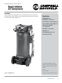
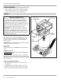
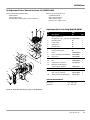
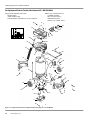
1
Rapid Inflation Air
Compressor
Operating Instructions and Parts Manual
WL6700 Series
Française: Page 20
Español: página 40
MAKES IT EASY TO DO IT LIKE A PRO
Visit us at chpower.com
© 2009 Campbell Hausfeld/Scott Fetzer IN629500AV 4/09
Table of Contents
Description��������������������������������������������������� 3
Grounding Instructions������������������������� 11
Safety Guidelines����������������������������������������� 4
Wiring��������������������������������������������������������� 11
Safety Symbols��������������������������������������������� 4
Operation����������������������������������������������������� 12
Important Safety Information����������������� 4
Moisture in Compressed Air����������������� 12
Instructions Pertaining to a Risk of Fire,
Electric Shock, or Injury to Persons ������4
Lubrication����������������������������������������������� 12
California Proposition 65��������������������������4
Click-To-Set Regulator Knob��������������� 12
Breathable Air Warning����������������������������� 4
Outlet (Tool) Pressure Gauge��������������� 13
DISCLAIMER OF WARRANTIES ������������4
Tank Pressure Gauge����������������������������� 13
General ��������������������������������������������������������4
Storage Top����������������������������������������������� 13
Work Area����������������������������������������������������5
Rapid Inflation Technology ����������������� 13
Personal Safety��������������������������������������������5
To use compressor for Inflation: ��������� 13
Electrical Safety������������������������������������������5
Use and Care ����������������������������������������������5
To use compressor for Air Tool
Usage:��������������������������������������������������������� 13
Spraying Precautions��������������������������������6
End of Operation/Storage��������������������� 14
Air Source����������������������������������������������������6
Maintenance����������������������������������������������� 14
Service����������������������������������������������������������6
ASME Safety Valve����������������������������������� 14
Save These Instructions
Do Not Discard ������������������������������������������6
Drain Tank ����������������������������������������������� 14
Unpacking����������������������������������������������������� 7
Air Filter����������������������������������������������������� 15
Contents in the Carton������������������������������7
Lubrication����������������������������������������������� 15
Additional Items Not Included���������������7
Thermal Overload Protector����������������� 15
Glossary��������������������������������������������������������� 8
Torque Requirements ��������������������������� 15
Getting To Know Your Compressor ������� 9
Technical Service������������������������������������� 15
Unpacking����������������������������������������������������� 9
Troubleshooting Guide ��������������������������� 16
Recommended Uses for this
Compressor ������������������������������������������������9
Replacement Parts List for Pump,
Model WL390100��������������������������������������� 17
ASME Safety Valve����������������������������������� 12
Cleaning���������������������������������������������������� 15
Assembly ����������������������������������������������������� 10
TorqueRequirements����������������������������� 17
Tools Required for Assembly��������������� 10
Handle Assembly������������������������������������� 10
Replacement Parts List for Rapid
Inflation Air Compressor������������������������� 19
Inflation Hose Assembly����������������������� 10
Warranty ����������������������������������������������������� 20
Installation ������������������������������������������������� 10
Location����������������������������������������������������� 10
Wheel Lock/Foot Brake������������������������� 11
Electrical Installation����������������������������� 11
For parts, product and service information
Visit: www.chpower.com
Call:
Address any correspondence to:
Customer Service at 1-800-543-6400
Campbell Hausfeld
Attn: Customer Service
100 Production Drive
Harrison, OH 45030 U.S.A.
Operating Instructions and Parts Manual
Rapid Inflation
Air Compressor
Description
Oilless compressors are designed for do-it-yourselfers with a variety of home and
automotive jobs. These compressors power spray guns, impact wrenches and other
tools. These units operate without oil.
Specifications
WL6700 Series
Running HP: 1.7 (ISO 1217)
Free Air CFM: 3.8 @ 90 psi (ISO 1217)
Free Air CFM: 5.6 @ 40 psi (ISO 1217)
Tank Capacity (gallons):
18, 22, 26, or 30
Volts, Phase: 120 V, single
Amp Draw: 15
Max. Working Pressure: 150
Max. Duty Cycle: 50%
Record the model number and serial
number, located on the back of the tank,
and date of purchase in the space below.
Model #: ____________________________
Serial #: _____________________________
Date of Purchase: ____________________
Figure 1 - WL6700 Series
Retain these numbers for future reference.
www.chpower.com
3
Operating Instructions and Parts Manual
Important Safety Information
Safety Guidelines
This manual contains information
that is very important to know and
understand. This information is
provided for SAFETY and to PREVENT
EQUIPMENT PROBLEMS. To help
recognize this information, observe the
following symbols.
Instructions Pertaining to a Risk of Fire, Electric Shock, or Injury
to Persons
This manual contains important safety, operational and maintenance information. If
you have any questions, please call 1-800-543-6400 for customer assistance.
Since the air compressor and other components (material pump, spray guns, filters,
lubricators, hoses, etc.) used, make up a high pressure pumping system, the following
safety precautions must be observed at all times:
California Proposition 65
Danger indicates
an imminently
hazardous situation which, if not avoided,
WILL result in death or serious injury.
This product or its power cord may contain chemicals, including lead,
known to the State of California to cause cancer and birth defects or
other reproductive harm. Wash hands after handling.
Warning indicates
a potentially
hazardous situation which, if not avoided,
COULD result in death or serious injury.
You can create dust when you cut, sand, drill or grind
materials such as wood, paint, metal, concrete, cement, or
other masonry. This dust often contains chemicals known to cause cancer, birth
defects, or other reproductive harm. Wear protective gear.
Caution indicates a potentially
hazardous situation which, if not avoided,
MAY result in minor or moderate injury.
Notice indicates important
information, that if not followed, may
cause damage to equipment.
Breathable Air Warning
IMPORTANT: Information that
requires special attention.
Safety Symbols
The following Safety Symbols appear
throughout this manual to alert you
to important safety hazards and
precautions.
This compressor/pump is not equipped and should not be used “as is” to supply
breathing quality air. For any application of air for human consumption, the air
compressor/pump will need to be fitted with suitable in-line safety and alarm
equipment. This additional equipment is necessary to properly filter and purify
the air to meet minimal specifications for Grade D breathing as described in
Compressed Gas Association Commodity Specification G 7.1 - 1966, OSHA 29 CFR
1910. 134, and/or Canadian Standards Associations (CSA).
DISCLAIMER OF WARRANTIES
In the event the compressor is used for the purpose of breathing air application
and proper in-line safety and alarm equipment is not simultaneously used,
existing warranties shall be voided, and Campbell Hausfeld disclaims any liability
whatsoever for any loss, personal injury or damage.
General
Wear Eye and
Read Manual
Mask Protection First
Risk of Fire
a. To reduce the risks of electric shock, fire, and injury to persons, read
all the instructions before using the tool. Failure to follow warnings,
dangers, and cautions could result in DEATH or SERIOUS INJURY.
b. Be thoroughly familiar with the controls and the proper use of the
equipment. Follow all instructions. Contact your Campbell Hausfeld representative
if you have any questions.
Wear Eye and
Ear Protection
Hot Parts
Risk of Falling
c. Follow all local electrical and safety codes as well as in the US, National Electrical
Codes (NEC) and Occupational Safety and Health Act (OSHA).
d. Only persons well acquainted with these rules of safe operation should be
allowed to use the unit.
Risk of
Electrocution
4
Risk of
Explosion
www.chpower.com
Risk of Fumes
WL6700 Series
Important Safety Information (Continued)
Work Area
Electrical safety
a. Keep the work area clean and well lighted. Cluttered
benches and dark areas increase the risks of electric shock,
fire, and injury to persons.
Risk of electrical shock. Always
disconnect from power source before
servicing. Servicing should be performed by authorized
service center.
b. Keep bystanders, children, and visitors away while
operating. Distractions are able to result in the loss of
control. NEVER allow children in the work area.
Use and Care
Motors, electrical equipment
and controls can cause electrical
arcs that will ignite a flammable gas or vapor. Never
operate or repair in or near a flammable gas or vapor.
Never store or spray flammable liquids or gases in the
vicinity of the compressor.
c. To reduce fire hazard, keep engine/motor exterior free of
oil, solvent, or excessive grease.
Personal Safety
a. Stay alert. Watch what you are doing and use common
sense when operating the tool. Do not use the tool
while tired or under the influence of drugs, alcohol, or
medication. A moment of inattention while operating the
tool increases the risk of injury to persons.
Ensuring that the tool is used
only when the operator and all
other personnel in the work area are wearing ANSI Z87
eye protection equipment, and when required, other
appropriate protection equipment such as head, hearing
and foot protection equipment. Serious eye or permanent hearing loss
could result.
b. Always wear hearing protection when using the tool.
Prolonged exposure to high intensity noise is able to cause
hearing loss.
c. Always work in a well-ventilated area. Wear OSHAapproved dust mask.
d. Dress properly. Do not wear loose clothing or jewelry.
Contain long hair. Keep hair, clothing, and gloves away
from moving parts. Loose clothes, jewelry, or long hair
increases the risk of injury to persons as a result of being
caught in moving parts.
Compressor parts may be hot even if
the unit is stopped.
e. Keep fingers away from a running compressor;
fast moving and hot parts will cause injury and/or
burns.
f. Do not overreach. Keep proper footing and
balance at all times. Proper footing and balance
enables better control of the tool in unexpected
situations.
Never use plastic (PVC) pipe for
compressed air. Serious injury or
death could result.
a. Before each use, inspect compressed air
system and electrical components for signs of damage,
deterioration, weakness or leakage. Repair or replace
defective items before using.
b. Check all fasteners at frequent intervals for proper
tightness.
c. Check air hoses for weak or worn condition before each
use. Make sure all connections are secure.
d. Do not stand on or use the pump or unit as a handhold.
e. If the equipment should start to abnormally vibrate, STOP
the engine/motor and check immediately for the cause.
Vibration is generally a warning of trouble.
Never remove or attempt to adjust safety valve.
Keep safety valve free from paint and other
accumulations.
f. Do not alter or tamper with the safety relief valve. In the
event that the safety relief valve is tampered with, existing
warranties shall be voided and Campbell Hausfeld disclaims
any liability whatsoever for any loss, personal injury or
damage.
Never attempt to repair or modify
a tank! Welding, drilling or any
other modification will weaken the tank resulting in
damage from rupture or explosion. Always replace worn or
damaged tanks.
Drain liquid from tank daily.
g. Make sure to drain tank regularly and inspect periodically
for unsafe conditions such as rust formation and
corrosion. Tanks rust from moisture build-up, which
weakens the tank.
h. Release air slowly when draining moisture or
depressurizing the compressor system. Fast moving air will
stir up dust and debris which may be harmful.
i. Do not remove any warning labels from the unit.
j. Store inside. Do not store outside or in direct sunlight.
www.chpower.com
5
Operating Instructions and Parts Manual
Important Safety Information (Continued)
Spraying Precautions
Do not spray flammable materials in vicinity of open flame
or near ignition sources including the compressor unit.
a. Do not smoke when spraying paint, insecticides, or other flammable
substances.
b. Use a face mask/respirator when spraying and spray in a well
ventilated area to prevent health and fire hazards.
c. Do not direct paint or other sprayed material at the compressor.
Locate compressor as far away from the spraying area as possible to
minimize overspray accumulation on the compressor.
d. When spraying or cleaning with solvents or toxic chemicals,
follow the instructions provided by the chemical
manufacturer.
Air Source
Air compressors providing air to the tank should follow the requirements
established by the American National Standards Institute Standard
B19.3-1991; Safety Standard for Compressors for Process Industries. Contact your air
compressor manufacturer for information.
Service
a. Release air pressure from air tank by pulling safety relief ring before servicing or
replacing parts.
b. Service must be performed only by qualified repair personnel.
Never attempt to repair or modify a tank! Welding, drilling or any other
modification will weaken the tank resulting in damage from rupture or
explosion. Always replace worn or damaged tanks.
c. When servicing a tool, use only identical replacement parts. Use only authorized
parts.
NOTE: The DANGER, WARNING, CAUTION, and NOTICE notifications and instructions
in this manual cannot cover all possible conditions and situations that may occur. It must be
understood by the operator that common sense and caution are factors which cannot be built
into this product, but must be supplied by the operator.
Save These Instructions
Do Not Discard
6
www.chpower.com
WL6700 Series
Unpacking
After unpacking the unit, inspect carefully
for any damage that may have occurred
during transit. Check for loose, missing
or damaged parts. Make sure to tighten
fittings, bolts, etc., before putting unit
into service. Check to be sure all supplied
accessories are enclosed with the unit. In
case of questions, damaged or missing
parts, please call 1-800-543-6400 for
customer assistance.
Self-tapping
screws
u Do not operate unit if damaged during
Nylon
recoil hose
Blow gun
Handle
Blow gun
accessories
Tire
inflation
valve
shipping, handling or use. Damage may
result in bursting and cause injury or
property damage.
u For your own safety, never operate unit
until all assembly steps are complete and
until you have read and understood the
entire operator’s manual.
u To reduce the risk of injury, if any parts are
missing, do not attempt to assemble the
air compressor until the missing parts are
obtained and installed correctly.
Contents in the CARTON
u Blow gun accessories
u Handle with grip
u Blow gun
u Nylon recoil hose
u (4) Self-tapping screws
u Tire inflation valve
u Operating Instructions and Parts
Manual
u Warranty Card
Additional Items Not Included
u Air Hose
u ANSI Z87 Eye Protection
u Hearing Protection
u Other Personal Protective Gear as
required
Read & Follow All Instructions
Save These Instructions
Do Not Discard
Figure 2 - Unpacking
www.chpower.com
7
Operating Instructions and Parts Manual
Glossary
Become familiar with these terms before operating the unit.
Air Delivery - A combination of psi and SCFM. The air delivery required by
a tool is stated as (number) SCFM at (number) psi. The combination of these
figures determines what size unit is needed.
Air Tank Capacity - The volume of air stored in the tank and available for
immediate use. A large tank allows the intermittent use of an air tool with an air
requirement higher than the compressor’s rated delivery.
ASME Safety Valve - This valve automatically releases air if the tank pressure
exceeds the preset maximum.
Figure 3 - ASME Safety Valve
Click-to-set Regulator - The regulator controls the amount of air pressure
released at the hose outlet to the proper amount needed to operate an air tool or
spray gun.
Cut-in/Cut-off Pressure - Specific psi at which a compressor starts and
stops while refilling the air tank.
Easy Drain Knob - This knob is used to drain moisture from the tank daily to
reduce the risk of corrosion.
Figure 4 - Click-To-Set Regulator
Foot Pedal On/Off Switch - Used to turn the compressor on and off.
Motor Protection - If the unit is over worked, a thermal switch will shut
unit off. If this happens, turn unit OFF the ON/OFF Switch, wait 30 minutes to
cool, turn ON the ON/OFF Switch again to resume work.
Outlet (Tool) Pressure Gauge - Displays the current outlet pressure to the
tool in psi. It is regulated by the regulator knob.
Pressure Switch -Shuts the compressor off automatically when tank
pressure reaches the maximum preset pressure. The compressor will
automatically restart when it reaches the minimum preset pressure.
Figure 5 - Easy Drain Knob
PSI (Pounds per Square Inch) - Measurement of the pressure exerted by
the force of the air. The actual psi output is measured by a pressure gauge on the
compressor.
SCFM (Standard Cubic Feet per Minute) - Sometimes called CFM (Cubic
Feet per Minute). Measurement of air volume delivered by the compressor.
Tank Pressure Gauge - Indicates tank pressure in psi.
Figure 6 - Foot Pedal ON/OFF Switch
Tool Storage - The open space on top of compressor is designed for tool
storage. Specific Campbell Hausfeld tool kits will fit in this storage area.
Figure 7 - Tank Pressure Gauge
8
www.chpower.com
WL6700 Series
Unpacking
Getting
To Know Your Compressor
Recommended Uses for this
Compressor
Hose/outlet
pressure
u Auto maintenance
u Auto restoration
u Fastening
u Home maintenance
Click-to-set
regulator
u Inflation
u Woodworking
Power
cord clip
Coupler
Power
cord
Tool Recommendation for this
Compressor
Foot pedal on/off switch
Wheel lock /
foot brake
Storage trays
Blow gun
clip
Tank pressure
gauge
Easy-drain knob
Pull handle
ASME
Safety
valve
Easy-drain cup
Continuous Use —
Inflation accessories
Airbrush
Air screwdrivers
Brad nailers and Staplers
Caulk guns
Engine cleaners
Finish nailers
Grease guns
Home spray guns
Impact wrench
Ratchets
Reciprocating saws
Roofing and Framing nailers
Intermittent Use
(Short powerful bursts) —
Air chisels
Air drills
Automotive spray guns
Die grinders
Tools Not Recommended —
Cut-off tools
Dual action sanders
Highspeed sanders
Jitterbug sanders
Straight line sanders
Safety
blow gun
Instant-air
hose
Figure 8 - Components of the compressor
www.chpower.com
9
Operating Instructions and Parts Manual
Assembly
Tools Required for Assembly
u Screwdriver
u (2) Wrenches
Handle Assembly
1. Slide handle into shroud holes until
the holes of the handle line up with
the holes of the tank bracket.
2. Insert and tighten screws to hold the
handle in place.
Figure 9 - Handle assembly
Inflation Hose Assembly
1. Thread the coil hose into the fitting
on the shroud. Use 2 adjustable
wrenches, as shown in Figure 10, to
tighten the connection.
2. Screw blow gun onto the end of the
coil hose.
Once the recoil hose and blow gun are
attached, make sure no pressure is in
tank before replacing. Recoil hose and
blow gun must be installed for unit to
operate properly.
Installation
Location
When assembled, the tank must sit level
to allow the tank to drain properly.
It is extremely important to install the
compressor in a clean, well ventilated
area where the surrounding air
temperature will not be more than 100°F.
A minimum clearance of 18 inches
between the compressor and a wall is
required because objects could obstruct
air flow.
Do not locate the
compressor air inlet
near steam, paint spray, sandblast areas
or any other source of contamination. This
debris will damage the motor.
10
www.chpower.com
Figure 10 - Inflation hose assembly
WL6700 Series
Installation (Continued)
Wheel Lock/Foot Brake
To move the compressor, use your foot to lift the foot brake lever to disengage the
brake.
Once the compressor is at the desire location, use your foot to push down on the foot
brake lever to engage the brake.
Disengaged
Electrical Installation
Engaged
All wiring and electrical connections should be performed by a qualified
electrician. Installation must be in accordance with local codes and
national electrical codes.
Never use an extension cord with this product. Use additional
air hose instead of an extension cord to avoid power loss and
permanent motor damage.
STOP!
Figure 11 - Wheel Lock/Foot Brake
Grounding Instructions
1. This product is for use on a nominal 120 volt circuit and has a grounding plug that
looks like the plug illustrated in Figure 12. Only connect the product to an outlet
having the same configuration as the plug. Do not use an adapter with this product.
In the event of an electrical short circuit, grounding reduces risk of electrical shock
by providing an escape wire for electric current. This product is equipped with a
cord having a grounding wire with an appropriate grounding plug. Plug must be
plugged into an outlet that is properly installed and grounded in accordance with
all local codes and ordinances.
TEST
RESET
Figure 12 - Grounding method
Improper use of grounding plug can result in a possible risk
of electrical shock!
Do not use a grounding adapter with this product!
2. If repair or replacement of cord or plug is necessary, do not connect grounding wire
to either flat blade terminal. The wire with insulation having an external surface
that is green (with or without yellow stripes) is the grounding wire.
Never connect green (or green and yellow) wire to a live terminal.
3. Check with a qualified electrician or serviceman if grounding instructions are not
completely understood, or if in doubt as to whether product is properly grounded.
Do not modify plug provided; if it will not fit outlet, have proper outlet installed by a
qualified electrician.
Wiring
1. Local electrical wiring codes differ from area to area. Source wiring, plug and
protector must be rated for at least the amperage and voltage indicated on motor
nameplate, and meet all electrical codes for this minimum.
2. Use a slow blow fuse or a circuit breaker.
Overheating, short circuiting and fire damage will result from
inadequate wiring, etc.
NOTE: 120 volt, 15 amp units can be operated on a 120 volt circuit under the following
conditions:
a. No other electrical appliances or lights are connected to the same branch
circuit.
b. Voltage supply is normal.
c. Circuit is equipped with a 15 amp circuit breaker or a 15 amp slow blow fuse.
www.chpower.com
11
Operating Instructions and Parts Manual
Installation (Continued)
3. If these conditions cannot be met or if nuisance tripping
of current protection device occurs, it may be necessary to
operate compressor from a 120 volt, 20 amp circuit.
Operation
Moisture in compressed air
Moisture in compressed air will form into droplets as it
comes from an air compressor pump. When humidity is
high or when a compressor is in continuous use for an
extended period of time, this moisture will collect in the
tank. When using a paint spray or sandblast gun, this water
will be carried from the tank through the hose, and out of
the gun as droplets mixed with the spray material.
Outlet (Tool)
Pressure Gauge
IMPORTANT: This condensation will cause water spots
in a paint job, especially when spraying other than water
based paints. If sandblasting, it will cause the sand to cake
and clog the gun, rendering it ineffective. A filter in the air
line (MP3105), located as near to the gun as possible, will
help eliminate this moisture.
This compressor can be used for general inflation as well as
intermittent duty air tool usage. For inflation purposes, this
compressor utilizes a new technology called Rapid Inflation
Technology (RIT).
Tank
Pressure
Gauge
Click-to-set
regulator
ASME
Safety Valve
IMPORTANT: Make sure the Wheel Lock/Foot Brake is engaged
before operating the unit (See Figure 11).
Lubrication
This is an oilless product and does not require lubrication to
operate.
ASME Safety Valve
Do not remove or attempt to adjust the safety
valve!
This valve should be checked under pressure occasionally by
pulling the ring by hand (See Figure 13). If air leaks after ring has
been released, or valve is stuck and cannot be actuated by ring, it
MUST be replaced.
Click-To-Set Regulator Knob
1. This knob controls air pressure to an air operated tool, or
paint spray gun.
2. Turning knob clockwise increases air pressure at outlet.
3. Turning counterclockwise will lower air pressure at outlet.
4. Fully counterclockwise will shut off flow of air completely.
12
www.chpower.com
Storage Trays
Figure 13
WL6700 Series
Operation (Continued)
Outlet (Tool) Pressure Gauge
1. This gauge shows at-a-glance, air pressure at outlet. Air pressure is measured in
pounds per square inch (psi).
2. Be sure this gauge reads ZERO before changing air tools or disconnecting hose from
outlet.
Tank Pressure Gauge
Gauge shows pressure in tank indicating compressor is building pressure properly.
Storage Top
The storage tray compartments, located on the top of the compressor, are designed for
easy tool storage. Unique tool kits, available at your local retailer or on www.chpower.
com, store easily on top of the unit.
Rapid Inflation Technology
When the compressor is used in this mode, the air being produced from the
compressor pump will go directly to the recoil hose which will attach to the bottom of
the compressor. This will eliminate waiting for the compressor tank to fill up which will
allow for significantly faster inflation.
Figure 14 - Rapid Inflation Technology
Instant air hose will get hot while the compressor is
on and during the inflation process.
Drain water from tank prior to inflation.
To use compressor for inflation:
1. Connect recoil hose to open port located on the bottom of compressor (See Figures
10 and 14). The coil hose and blow gun must remain attached so that the unit
operates properly.
2. Attach blow gun to the other end of the recoil hose. The blow gun should ALWAYS
be connected to the recoil hose.
3. To inflate balls, rafts, etc. attach inflation needle or nozzle to the end of blow gun.
4. To inflate tires, attach tire inflation valve to the end of blow gun.
5. Attach the blow gun with appropriate inflation device to object needing inflation.
6. Turn on compressor and inflate by squeezing the trigger.
Figure 15
Use caution to avoid over inflation.
7. When inflation is complete, blow gun can be attached to the clip that is molded on
the side of the top shroud for convenient storage.
To use compressor for air tool usage:
1. Connect separate hose (not included) to the coupler located below pressure
regulator by pulling the sleeve on coupler all of the way back, then push hose into
coupler and release sleeve (See Figure 16).
2. Close regulator (turn knob fully counterclockwise to the left).
3. Turn compressor on and allow it to fill tank until it reaches automatic shut off
pressure.
4. Attach air tool, paint gun, nailer, etc. to end of air hose.
5. Adjust regulator for desired application. Regulator has preset “click-to-set” feature
which should closely match application pictures on outlet pressure gauge.
Figure 16 - Attach hose to coupler
6. Use compressor for desired application.
www.chpower.com
13
Operating Instructions and Parts Manual
Operation (Continued)
End of Operation/Storage
1. Turn compressor off at foot pedal on/off switch.
2. Unplug power cord from wall outlet and attach to clip that is molded on the side of
the top shroud.
3. Drain tank of condensation as outlined in the Drain Tank section below.
4. Wearing safety glasses, drain tank of any remaining air pressure by pulling the
ring on the safety valve. Use other hand to deflect any fast moving air that may be
directed towards your face.
5. Store compressor in a cool, dry place.
Maintenance
Disconnect power source then release all pressure from the
system before attempting to install, service, relocate or
perform any maintenance. Service should be performed by an authorized service
representative.
The compressor should be checked often for any visible problems and the
following maintenance procedures should be performed each time the compressor is
used.
ASME Safety Valve
Do not remove or attempt to adjust the safety valve!
Figure 17 - Safety valve
Check the safety valve by performing the following steps:
1. Plug the compressor in and run until shut off pressure is reached (see Operating
Procedure).
Tank Pressure
Gauge
2. Wearing safety glasses, pull the ring on the safety valve to release pressure from
compressor tank. Use your other hand to deflect fast-moving air from being
directed toward your face.
3. The safety valve should automatically close at approximately 40-50 psi. If the safety
valve does not allow air to be released when you pull on the ring, or if it does not
close automatically, it MUST be replaced.
Drain Tank
1. Turn compressor off at foot pedal switch.
2. Check air pressure in tank. To properly drain tank of condensation, tank pressure
should be between 20-60 psi. Drain system will not work if there is no pressure
in the tank. If tank pressure is above 60 psi, drain tank by pulling the ring on the
safety valve. The safety valve should release air and then automatically close at
approximately 40-50 psi.
3. Slowly turn easy drain knob, located below the tank gauge, to the left
(counterclockwise) until fluid begins to fill drain cup. Watch draining to make sure
drain cup does not overflow. If there is a lot of fluid in the tank, you may need to
close drain knob by turning fully to the right (clockwise) then remove the drain cup
to dispose of fluid.
4. When fluid stops draining, close drain knob by turning all the way to the right
(clockwise).
5. Lift cup up and pull out to dispose of drained fluid. Reinsert cup, making sure to
secure in place.
14
www.chpower.com
Easy-Drain
Knob
Fill Line
Easy-Drain Cup
Figure 18 - Draining tank
WL6700 Series
Maintenance (Continued)
Cleaning
Turn power OFF and clean dust and dirt from motor, tank, and
air lines.
IMPORTANT: Unit should be located as far from spraying area
as hose will allow to prevent over-spray from entering the pump.
Air FIlter
Check air filter to be sure it is clean. To service the air filter, tip
the unit back, resting the wheels and handle on the floor (See
Figure 19). Remove the filter housing cover. Remove filter and
blow off dirt. Replace air filter if it can not be cleaned. Place filter
back in the housing base. Replace cover.
Lubrication
This is an oilless type compressor requiring no lubrication.
Thermal overload protector
Air Filter
This compressor is equipped with an automatic
reset thermal overload protector which will shut
off motor if it becomes overheated.
If thermal overload protector shuts motor OFF frequently look
for the following causes:
Figure 19 - Air Filter
1. Low voltage
2. Lack of proper ventilation
If the thermal overload protector is actuated,
the motor must be allowed to cool down before
startup is possible. The motor will automatically restart without
warning if left plugged into electrical outlet and unit is turned on.
Torque requirements
Piston Bolt . . . . . . . . . . . . . . . . . . . . . . 350 - 450 in. Ibs.
Head Bolts . . . . . . . . . . . . . . . . . . . . . . 90 - 120 in. Ibs.
Technical Service
For information regarding the operation or repair of this
product, please call
1-800-543-6400.
www.chpower.com
15
Operating Instructions and Parts Manual
Troubleshooting Guide
Symptom
cause
solution
Compressor will not run
1. No electrical power
1. Plugged in? Switch on? Check fuse/breaker
2. Breaker open
2. Reset, determine cause of problem
Fuses blow/circuit breaker
trips repeatedly
3. Pressure switch bad
3. Replace
4. Motor over worked
4. Turn off, let cool, turn on.
5. Tank pressure above cut-in
5. Bleed tank pressure down to cut-in.
1. Incorrect size fuse, circuit overloaded
1. Check for proper fuse, use time-delay fuse.
Disconnect other electrical appliances from circuit
or operate compressor on its own branch circuit
2. Worn check valve
2. Replace
Tank pressure drops when
compressor shuts off
Air output lower than
normal/low discharge
pressure
Excessive moisture in
discharge air
Compressor runs
continuously
Motor runs but no air output
16
www.chpower.com
Do not disassemble check valve with air in tank; bleed tank
1. Loose connections (fittings, tubing,
etc.)
1. Check all connections with soap and water
solution. Tighten; or remove and apply pipe dope
or pipe tape to the threads, then reassemble.
2. Open tank drain
2. Close drain
1. Air leaks in piping (on machine or in
outside system)
1. Check all connections with soap and water
solution. Tighten; or remove and apply pipe dope
or pipe tape to the threads, then reassemble.
2. Piston ring worn
2. Replace
3. Excessive air usage
3. Decrease air usage; compressor not large enough
for air requirement
4. Open tank drain
4. Close tank drain
1. Excessive water in tank
1. Drain tank
2. High humidity
2. Move to area of less humidity; use air line filter
1. Defective pressure switch
1. Replace switch
2. Excessive air usage
2. Decrease air usage; compressor not large enough
for air requirement
Belt worn
Replace belt
WL6700 Series
For Replacement Parts or Technical Assistance, Call 1-800-543-6400
Please provide following information:
Address any correspondence to:
- Model number
Campbell Hausfeld
- Serial number (if any)
Attn: Customer Service
- Part description and number as shown in parts list
100 Production Drive
Harrison, OH 45030 U.S.A.
11
Replacement Parts List for Pump, Model WL390100
13
1
2
3
4
5
6
7
8
9
10
11
12
13
14
8
7
6
3
Ref.
Part
No.
DescriptionNo.Qty.
5
4
2
Motor assembly kit
(Includes #2, 3, 6, 7, 10, 12, & 14) WL019100SJ
Cylinder gasket
▲
Intake valve
▲
Valve plate
▲
Exhaust valve
▲
Head gasket
▲
Exhaust valve gasket
▲
Head
WL010500AV
Piston assembly (Includes #10) WL211000SJ
Piston bolt
ST071804AV
Head bolt
●
Fan
WL008400AV
Compression connector
ST159001AV
Belt kit (Includes #10, 12,
check valve, & ferrules)
WL015303SJ
1
1
1
1
1
1
1
1
1
1
4
1
1
1
REPLACEMENT PARTS KITS
9
12
1
10
● Head bolt kit
(Set of 4 ea., part #11)
WL211100AJ
1
▲ Valve plate kit (Includes #2-7)
WL211201SJ
1
Torque requirements
14
Piston Bolt . . . . . . . . . . . . . . . . . . . . . . 350 - 450 in. Ibs.
Head Bolts . . . . . . . . . . . . . . . . . . . . . . 90 - 120 in. Ibs.
Figure 20 – Repair Parts Illustration for pump, model WL390100
www.chpower.com
17
Operating Instructions and Parts Manual
For Replacement Parts or Technical Assistance, Call 1-800-543-6400
Please provide following information:
Address any correspondence to:
- Model number
Campbell Hausfeld
- Serial number (if any)
Attn: Customer Service
- Part description and number as shown in parts list
100 Production Drive
Harrison, OH 45030 U.S.A.
20
18
57
24
19
23
22
29
56
25
28
27
21
55
26
53
31
30
17
1
52
4
47
48
45
46
50
49
51
44
16
39
28
36
15
12
2 34
11
3
7
28
27
8
40
41
6
42
35
5
14
9
10
Figure 21 – Repair Parts Illustration for Rapid Inflation Air Compressor, model WL6701
www.chpower.com
33
28
13
18
38
54
43
20
37
27
32
WL6700 Series
Replacement Parts List for Rapid Inflation Air Compressor
Ref.
Part
No.
DescriptionNo.Qty.
Ref.
Part
No.
DescriptionNo.Qty.
1
AR062700CG 1
36
26 Gallon Tank
Wheel - 10” OD Black Hub
WA004000AV 2
2
Rubber Grommet
WL008000AV 1
37
Axle Bolt
ST033400AV 2
3
Bottom Front Shroud
WL045000AV 1
38
Wheel Cog Gear
H
1
4
Lower Caster Side Shroud
WL044900AV 1
39
Brake Bracket Mount
H
1
5
Millenium Pump/Motor Assembly WL212000SJ 1
40
Brake Locking Arm
H
1
6
Caster Swivel Wheel 2 in. Diameter
41
#8 X 1.50 in. Plastic Screw
m
4
s 2
42
#12 X 1.75 in. Plastic Screw
m
4
7
Check Valve
CV309100AV 1
43
Hex Keps Nut
s
2
8
Pressure Switch
CW218300AV 1
44
Drain Valve
D-140700AV 1
9
Pump/Motor Shroud
n
1
45
Jam Nut and Washer Set
6
10
#8 X .375 Self-Tapping Screw
n
4
46
Drain Knob and Screw
WL046100AV 1
11
Push Type - Straight Tube Fitting ST119305AV 1
47
Pressure Gauge, 1.5 in. Diameter GA032900AV 1
12
Exhaust Tube
l
1
48
1/4 - 18 Pipe Plug
13
Instant Air Tube
u
1
49
14
Filter
WL026100AV 1
50
15
Strain Relief
WL012700AV 1
51
Safety Valve
V-215106AV
16
Power Cord
EC012601AV 1
52
Tube to Hose Fitting
ST196000AV 1
17
Top Skirt
WL044700AV 1
53
50 ft. Recoil Hose
MP287400AV 1
18
Top Shroud
WL044600AV 1
54
Screw - Hex Head Machine
H
19
1/4 in. X 1.50 in. Plastic Screw
t
2
55
Lever Safety Blow Gun
MP216700AV 1
20
1/4-20 X .75 Self-Tapping Screw t
12
21
Regulator Assembly
RE300200AV 1
56
Tire Inflation Valve with
Whip Hose
HF229900AV 1
Blowgun Inflator Kit
MP211600AV 1
1
†
1
Drain Shroud and Cup
6
1
Drain Tube with Weight
WL046300AV 1
22
Regulator Knob
w
1
57
23
#10 X .75 Self-Tapping Screw
w
1
REPLACEMENT PARTS KITS
24
Regulator Knob Cover
w
1
s
Caster Wheel Kit
WA005900AJ
25
3 in. Outlet Gauge
GA032700AV 1
n
Shroud kit
WL042900AJ
26
1/4” NPT Male Universal Coupler HF203300AV 1
27
Washer - Plain Type “A”
t H
6
l
Exhaust Tube Kit
(includes nuts and ferrules)
WL046600AJ
28
Torx Button Head Screw
t m H
10
29
Control Panel without Switch
WL042200AV 1
u
Instant Air Tube Kit
(includes nuts and ferrules)
WL046900AJ
30
Handle
o
1
t
Upper Shroud Hardware Kit
ST172200AJ
31
1/4-20 X 1.25 Self-Tapping Screw o
4
w
Regulator Knob Kit
RE300300AJ
32
On/Off Switch
ST196400AV 1
o
Handle Kit
HL037700AJ
33
On/Off Pedal
WL044500AV 1
m
Lower Shroud Hardware Kit
ST172300AJ
34
Eccentric Cover
WL044400AV 1
H
Brake Assembly
WL047000AJ
35
Motor Bracket
BA018300AV 1
6
Shroud And Drain Cup Assembly WL046200AJ
†
Standard Hardware Item
www.chpower.com
1
1
19
Operating Instructions and Parts Manual
Reminder: Keep your dated proof of purchase for warranty purposes! Attach it to this manual or file it for safekeeping.
Warranty
1. DURATION: From the date of purchase by the original purchaser as follows: One Year.
2. WHO GIVES THIS WARRANTY (WARRANTOR): Campbell Hausfeld / Scott Fetzer Company, 100 Production Drive, Harrison,
Ohio, 45030, Telephone: (800) 543-6400
3. WHO RECEIVES THIS WARRANTY (PURCHASER): The original purchaser (other than for purposes of resale) of the Campbell
Hausfeld product.
4. WHAT PRODUCTS ARE COVERED BY THIS WARRANTY: Any Campbell Hausfeld nailer, stapler, air tool, spray gun, inflator or
air accessory supplied or manufactured by Warrantor.
5. WHAT IS COVERED UNDER THIS WARRANTY: Substantial defects in material and workmanship which occur within the
duration of the warranty period.
6. WHAT IS NOT COVERED UNDER THIS WARRANTY:
A. Implied warranties, including those of merchantability and FITNESS FOR A PARTICULAR PURPOSE ARE LIMITED FROM
THE DATE OF ORIGINAL PURCHASE AS STATED IN THE DURATION. If this product is used for commercial, industrial or
rental purposes, the warranty will apply for ninety (90) days from the date of purchase. Some States do not allow limitation
on how long an implied warranty lasts, so the above limitations may not apply to you.
B. ANY INCIDENTAL, INDIRECT, OR CONSEQUENTIAL LOSS, DAMAGE, OR EXPENSE THAT MAY RESULT FROM ANY
DEFECT, FAILURE, OR MALFUNCTION OF THE CAMPBELL HAUSFELD PRODUCT. Some States do not allow the
exclusion or limitation of incidental or consequential damages, so the above limitation or exclusion may not apply to you.
C. Any failure that results from an accident, purchaser’s abuse, neglect or failure to operate products in accordance with
instructions provided in the owner’s manual(s) supplied with product. Accident, purchaser’s abuse, neglect or failure to
operate products in accordance with instructions shall also include the removal or alteration of any safety devices. If such
safety devices are removed or altered, this warranty is void.
D. Normal adjustments which are explained in the owner’s manual(s) provided with the product.
E. Items or service that are normally required to maintain the product, i.e. o-rings, springs, bumpers, debris shields, driver
blades, fuses, batteries, gaskets, packings or seals, fluid nozzles, needles, sandblast nozzles, lubricants, material hoses, filter
elements, motor vanes, abrasives, blades, cut-off wheels, chisels, chisel retainers, cutters, collets, chucks, rivet jaws, screw
driver bits, sanding pads, back-up pads, impact mechanism, or any other expendable part not specifically listed. These
items will only be covered for ninety (90) days from date of original purchase. Underlined items are warranted for defects in
material and workmanship only.
7. RESPONSIBILITIES OF WARRANTOR UNDER THIS WARRANTY: Repair or replace, at Warrantor’s option, products or
components which are defective, have malfunctioned and/or failed to conform within duration of the warranty period.
8. RESPONSIBILITIES OF PURCHASER UNDER THIS WARRANTY:
A. Provide dated proof of purchase and maintenance records.
B. Deliver or ship the Campbell Hausfeld product or component to the nearest Campbell Hausfeld Authorized Service Center.
Freight costs, if any, must be borne by the purchaser.
C. Use reasonable care in the operation and maintenance of the products as described in the owner’s manual(s).
9. WHEN WARRANTOR WILL PERFORM REPAIR OR REPLACEMENT UNDER THIS WARRANTY: Repair or replacement will
be scheduled and serviced according to the normal work flow at the servicing location, and depending on the availability of
replacement parts.
This Limited Warranty applies in the United States, Canada and Mexico only and gives you specific legal rights. You may also have
other rights which vary from state to state or country to country.
20
www.chpower.com