1
REV.2011.7.22
80 SERIES
Advanced Remote Starters & Vehicle Security Systems
AUTOMATIC AND MANUAL TRANSMISSION MODELS*
*MUST USE M SERIES REMOTE STARTER!
WARING: NEVER USE AN AUTOMATIC TRANSMISSION
STARTER IN A MANUAL TRANSMISSION VEHICLE
80 SERIES
IMPORTANT NOTES...........................................................................................PAGE 3
QUICK VIEW OPERATIONS...............................................................................PAGES 4-5
LOCK
UNLOCK
TRUNK START
STOP
SYSTEM OPERATIONS DETAILED...................................................................PAGES 6-13
LOCK
UNLOCK
TRUNK START
STOP
COLD START MODE...........................................................................................PAGE 14
TIME AND TEMPERATURE SETTINGS
SERVICE MODE.................................................................................................PAGE 15
OVERRIDE MODE/ SERVICE MODE
TRANSMITTER PROGRAMMING......................................................................PAGE 16
SHOCK SENSOR PROGRAMMING (ALARM MODELS)...................................PAGE 17
SHOCK SENSOR ADJUST
SHOCK SENSOR BYPASS
DIAGNOSTICS....................................................................................................PAGE 18
DIAGNOSTICS CHART
DIAGNOSTIC MEMORY
WARRANTY.........................................................................................................PAGE 19
CONTACT INFO..................................................................................................PAGE 20
80 SERIES
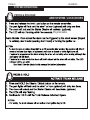
IMPORTANT NOTES
BEFORE YOU START
80 SERIES
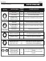
BUTTON
LOCK
PAGE 4
BUTTON PRESS
SYSTEM FUNCTION
1 SECOND
1
LOCK DOORS/ ARM ALARM
3 SECONDS
1
ACTIVATE PANIC MODE
PRESS THEN
RELEASE THEN
PRESS & HOLD
1
ACTIVATE CONSTANT LOCK OUTPUT
1 SECOND
2
UNLOCK DOORS/ DISARM ALARM
1 SECOND
WHILE ALARM IS
TRIGGERED
UNLOCK/
TRUNK
HONKS /
FLASH
NONE TURNS OFF ALARM/ DOOR STAY LOCKED
5 SECONDS
2
AUXILIARY #2 OUTPUT
PRESS & RELEASE
1
ACTIVATES REMOTE STARTER
PRESS & HOLD
2
TURN OFF REMOTE STARTER
PRESS AND HOLD
HOLD FOR 3 SEC
2
ON
AUXILIARY #1 OUTPUT (DEFAULT)
CAR FINDER (PROGRAMMABLE)
START
AUX
+
PRESS TOGETHER
THEN RELEASE
PRESS TOGETHER
THEN RELEASE
1
2
ACTIVATES SILENT LOCK WITHOUT
CHIRPS
ACTIVATES SILENT UNLOCK WITHOUT
CHIRPS
80 SERIES
PAGE 5
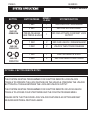
BUTTON
+
2ND CAR
OPERATION
BUTTON PRESS
HONKS /
FLASH
SYSTEM FUNCTION
1 SEC
1
2ND CAR LOCK / ARM ALARM
3 SEC
1
2ND CAR ACTIVATE PANIC
PRESS /RELEASE
THEN PRESS & HOLD
1
2ND CAR ACTIVATE CONSTANT LOCK
OUTPUT
+
1 SEC
2
2ND CAR UNLOCK / DISARM ALARM
2ND CAR
OPERATION
3 SEC
2
UNLOCK THEN TRUNK RELEASE
+
1 SEC
1
2ND CAR REMOTE START
2ND CAR
OPERATION
3 SEC
2
2ND CAR REMOTE SHUTDOWN
OPTIONAL 2 BUTTON REMOTE NOTES
THE SYSTEM MUST BE PROGRAMMED FOR 2 BUTTON REMOTE LOCK/UNLOCK
TOGGLE TO OPERATE THE LOCK FEATURE ON THE VEHICLE. PRESSING THE UNLOCK
BUTTON WILL TOGGLE BETWEEN THE LOCK AND UNLOCK OUTPUT.
THE SYSTEM MUST BE PROGRAMMED FOR 2 BUTTON REMOTE OR LOCK/UNLOCK
TOGGLE TO ACCESS COLD START MODE AND THE FOURTH PROGRAM MENU.
PLEASE NOTE THAT THE DOOR LOCK/ UNLOCK FEATURE IS AN OPTION AND MAY
REQUIRE ADDITIONAL PART AND LABOR.
80 SERIES
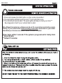
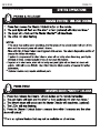
1. Press and release the Start button on the remote transmitter.*
2. The park lights will flash and the siren**/ horn will chirp once.
3. The vehicle will remote start. The park lights will stay on during run time***
See diagnostic chart if your vehicle fails to start.
Note- Manual transmission vehicles must be set for reservation mode before remote
starting. If your vehicle starts without setting reservation mode return to your dealer
immediately as the incorrect remote starter has been installed.
*Press twice within 3 seconds if the system is programmed for Safety Start.
** Alarm Models
***Default 15 minutes
80 SERIES
*Press # twice on manual transmission models.
80 SERIES
OWNER'S MANUAL
PAGE 8
SYSTEM
PROGRAMMING
SYSTEM
OPERATIONS- Menu 1
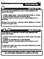
RESERVATION MODE
REQUIRED ON MANUAL TRANSMISSION VEHICLES ONLY. RESERVATION MODE
MUST BE SET TO REMOTE START THE VEHICLE.
RESERVATION MODE TYPE -1 (DEFAULT SETTING)
1) PLACE THE TRANSMISSION INTO NEUTRAL (VEHICLE RUNNING).
2) APPLY THE PARKING BRAKE.
3) PRESS AND RELEASE THE # BUTTON ON THE REMOTE.
THE PARK LIGHTS WILL FLASH AND THE HORN (IF CONNECTED) WILL HONK
TWICE.
4) REMOVE THE KEY. (THE VEHICLE WILL STAY RUNNING).
5) EXIT THE VEHICLE. THE ENGINE WILL SHUT OFF WHEN THE DOOR IS CLOSED.
THE SYSTEM CAN NOW BE ACTIVATED BY PRESSING THE START BUTTON.
RESERVATION MODE TYPE -2 (DEALER PROGRAMMABLE)
1) PLACE THE TRANSMISSION INTO NEUTRAL (VEHICLE RUNNING).
2) APPLY THE PARKING BRAKE.
THE PARK LIGHTS WILL FLASH AND THE HORN (OPTIONAL) WILL HONK TWICE.
3) REMOVE THE KEY. (THE VEHICLE WILL STAY RUNNING).
4) EXIT THE VEHICLE. THE ENGINE WILL SHUT OFF WHEN THE DOOR IS CLOSED.
THE SYSTEM CAN NOW BE ACTIVATED BY PRESSING THE START BUTTON.
RESERVATION MODE WILL CANCEL IF A DOOR IS RE- OPENED. TO ENTER THE
VEHICLE WITHOUT CANCELLING RESERVATION MODE REMOTE START THE
VEHICLE THEN SHUT THE SYSTEM OFF BY THE REMOTE ONCE THE DOORS ARE
CLOSED AGAIN.
80 SERIES
PAGE 9
SYSTEM OPERATIONS
SYSTEM PROGRAMMING
- Menu 1
OWNER'S MANUAL
PRESS & RELEASE
ARM SYSTEM / LOCK DOORS
Programmable.
80 SERIES
PAGE 10
PAGE 11
80 SERIES
*Not available on all models
80 SERIES
80 SERIES
80 SERIES
OWNER'S MANUAL
PAGE 14
SYSTEM
PROGRAMMING
SYSTEM
OPERATIONS- Menu 1
Timer Mode will start the vehicle at a user selectable start interval or by temperature.
The vehicle will start at the selected start interval/ temperature and run for the
programmed runtime*. EXAMPLE: If the 4 hour start cycle was selected, the vehicle
will start once every 4 hours. (Default 15 minutes)
Press and Hold
for 3 seconds or until the park lights turn on.
While the park lights are on the start cycle may be selected. See below:
PRESS
Sets for temp 1 (0c/ 32f) temp sensor must be installed. Programs for one hour start interval w/o temp sensor.
Sets for temp 2 (-5c/ 23f) temp sensor must be installed. Programs for two hour start interval w/o temp sensor.
Sets for temp 3 (-15c/5f) temp sensor must be installed. Programs on three hour start interval w/o temp sensor.
Sets for temp 4 (-25c/ -13f) temp sensor must be installed. Programs on four hour start interval w/o temp sensor.
NOTE: Timer Mode must be set each time the user wishes to use this feature.
Reservation Mode must be set (Manual Transmission Only) to enter Timer Mode.
To Cancel Timer Mode
Press and Hold
for 3 seconds or until the park lights flash twice.
Note- Timer Mode will automatically turn off after 24 hrs. Pressing the brake pedal or
turning the ignition to the ON position will also cancel Timer Mode.
IMPORTANT: Never remote start or set the Timer Mode if the vehicle is parked
in a Garage or Attached Carport!
80 SERIES
PAGE 15
SYSTEM OPERATIONS
SYSTEM PROGRAMMING
- Menu 1
OWNER'S MANUAL
SERVICE MODE
This feature is to be used when the vehicle is being serviced or if the remote
transmitter is lost or is not communicating with the system. This will disable the
remote starter from activating and disable the alarm of alarm models.
ACTIVATING SERVICE MODE
Turn the Ignition Key ON
(Leave in the ON position)
Press and hold the Valet switch for 8 to 15 seconds
(Time depends on "Valet Settings" Program Option)
The horn/ siren* will chirp 5 times as confirmation that the system
is in Service Mode. The LEDs on the antenna will turn on Solid.
DEACTIVATING SERVICE MODE
Turn the Ignition Key ON
(Leave in the ON position)
Press and hold the Valet switch for 8 to 15 seconds
(Time depends on "Valet Settings" Program Option)
The horn/ siren* will chirp 2 times as confirmation that Service
Mode is OFF. The LEDs on the antenna will turn on OFF.
*SIREN FUNCTION ON ALARM MODELS
80 SERIES
PAGE 16
OWNER'S MANUAL
SYSTEM
PROGRAMMING
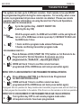
TRANSMITTER
PGM - Menu 1
The system can lean up to 4 different remote’s. Each remote to be used MUST
be programmed together during the same sequence. For security, when a new
remote is programmed all previous remote’s are deleted. Please see remote
operation chart for information on using Second Car / Pad Lock Operations.
ENTERING REMOTE PROGRAM MODE
12-
3-
Cycle the Ignition Key - ON/OFF ON/OFF ON
(Leaving the key ON)
HOLD the program switch, the HORN will honk ONCE and the park lights will
turn on. (If the HORN does not honk repeat step 1) CONTINUE TO HOLD until
the HORN honks 5 times
1 honk confirms program mode entered followed by
5 honks confirming transmitter program mode
PROGRAMMING REMOTE’S
4-
Press & Release LOCK (START ON 1172) button on 1st Remote to be
Programmed for Normal Operation If remote(s) are to be
programmed for "PADLOCK" skip and goto step 6.
5-
HORN will honk 1 time to confirm remote has been
programmed (If the HORN does not honk press button again)
REPEAT STEP 4 IF A SECOND REMOTE IS TO BE PROGRAMMED FOR NORMAL OPERATION
67-
Press & Release BUTTON 4 on Remote to be Programmed
for 2ND CAR OR PAD LOCK
HORN will honk 1 time to confirm remote has been
programmed (If the HORN does not honk press button again)
To program 2nd car operation on 2way models enter transmitter program mode and turn the # icon
on then program the transmitter to the vehicle. If the # icon is on the remote is in 2nd car operation.
REPEAT STEP 6 IF A SECOND REMOTE IS TO BE PROGRAMMED FOR 2ND CAR / PADLOCK OPERATION
8-
Turn ignition key OFF to exit remote program mode when
all required remote’s have been programmed.
80 SERIES
PAGE 17
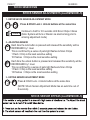
SHOCK SENSOR- PGM
SYSTEM PROGRAMMING
Menu 1
OWNER'S MANUAL
SHOCK SENSOR ADJUSTMENTS (ALARM MODELS)
1 - ENTER SHOCK SENSOR ADJUSTMENT MODE
Press & HOLD Lock + Unlock buttons at the same time
+
3 CHIRPS
Continue to hold for 3-5 seconds Until Siren Chirps 3 times
(Note: System will Arm or Disarm via silent arming prior to
entering adjustment mode)
2 - ADJUSTING SENSOR
Each time the lock button is pressed and released the sensitivity will be
INCREASED by 1 level.
This is confirmed by a series of park light flashes & Siren Chirps
1 Flash / Chirp is the least sensitive setting
10 Flashes / Chirps is the most sensitive setting
Each time the unlock button is pressed and released the sensitivity will be
DECREASED by 1 level.
This is confirmed by a series of park light flashes & Siren Chirps
1 Flash / Chirp is the least sensitive setting
10 Flashes / Chirps is the most sensitive setting
3 - EXITING SENSOR ADJUSTMENT MODE
+
Press & HOLD Lock + Unlock buttons at the same time
(NOTE: Shock Sensor Adjustment Mode has an auto time out of
8 seconds)
SHOCK SENSOR BYPASS (ALARM MODELS)
80 SERIES
PAGE 18
OWNER'S MANUAL
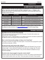
SYSTEMDIAGNOSTICS
PROGRAMMING - Menu 1
ALARM STATUS / DIAGNOSTICS
Diagnostic Mode is a tool that can help trouble shoot a start fault. If the remote starter fails to
start i.e.: the hood is open the park likes will flash a diagnostic code. i.e.: 5 flashes = start
attempt with hood open. If the vehicle does not remote start, count the park light flashes then
compare it to the chart below.
PARK LIGHTS
LED FLASHES
DIAGNOSTICS / STATUS
3 SLOW FLASHES
4 SLOW FLASHES
5 SLOW FLASHES
5 FLASHES
6 FLASHES
7 FLASHES
8 FLASHES
LED’s ON SOLID
SERIES OF 8 FLASHES
SERIES OF 5 FLASHES
SERIES OF 5 FLASHES
SERIES OF 6 FLASHES
SERIES OF 7 FLASHES
SERIES OF 8 FLASHES
SYSTEM IS IN SERVICE MODE.
NOT SET IN RESERVATION MODE “M” MODELS
START ATTEMPT WHILE IGNITION IS ON
START ATTEMPT WITH HOOD SWITCH OPEN
START ATTEMPT WITH BRAKE APPLIED
SYSTEM IS IN TACH LOCK OUT (SEE DEALER)
THREE START ATTEMPTS WITH NO START
The start fault must be corrected in order for the system to operate correctly. See your dealer
for additional trouble shooting or visit www.ultrastarters.com and visit the support page..
TROUBLE SHOOTING
The LED's do not turn on when Tach Learning?
1) The Tach wire input may be connected to the wrong wire. Check the Tach location and
connection then "reset and relearn".
2) The system may be in Tachless Mode. On TL models the Tach wire connection is optional and
the LED's do not turn on during the 35 second learn procedure.
When I unlock the doors the windows roll down or the Trunk Pops?
This issue is caused by the length of the unlock pulse. To correct this issue program the system
for short door lock pulses. (125ms)
The alarm activates 30-45 minutes after setting it?
To prevent the vehicles battery from going dead the computer will "hibernate" like your home
computer might. In some vehicles this causes the door pin input to change state. The alarm
detects the change of state and activates. A relay must be installed to isolated the door pin
circuit from the alarm.
The starter motor stays engaged to long when remote started?
Reset then relearn the Tach with the transmission in reverse. If the vehicle is tach learned when
the idle is high the starter motor may "drag". Check your ground connection if issues persist.
PAGE 19
WARRANTY- Menu 1
SYSTEM PROGRAMMING
80 SERIES
OWNER'S MANUAL
WARRANTY
Applicated Security Technologies, Inc. ("AST") promises to the original purchaser to repair or replace with
a comparable reconditioned model any AST control module ("module") excluding without limitation the
any other accessories, including but not limited to the antenna, remote, siren and wiring harness, proves
to be defective in workmanship or material under reasonable use during the lifetime of the vehicle it was
originally installed, provided the following conditions have been met: the module was professionally
installed and serviced by an authorized AST dealer; the unit will be professionally reinstalled in the
vehicle in which it was originally installed by an authorized AST dealer; the warranty information card was
sent to AST within 10 days of the original installation date. Any warranty returns include a warranty return
authorization number issued by AST, original bill or sale and be pre-paid shipped directly to AST. After an
initial period of 2 years from the date of installation, AST reserves the right, at its sole discretion, to
charge a warranty processing fee of $30.00 USD. AST does not cover the cost for return freight on
warranty items, this cost is the sole responsibility of the purchaser.
All components included with the original packaged unit other than the module, including but not limited to
the siren, antenna and the remote transmitters, carry a one-year warranty from the date of purchase of
the same. Any warranty returns on components must include a warranty return authorization number
issued by AST, original bill or sale and be pre-paid shipped directly to AST. This warranty is nontransferable and is automatically void if: the original purchaser has not completed the warranty card and
mailed it within ten (10) days of the date of purchase to the address listed on the card; the unit's date
code or serial number is defaced, missing or altered; the unit has been modified or used in a manner
contrary to its intended purpose; the unit has been damaged by accident, unreasonable use, neglect,
improper service, installation or other causes not arising out of defects in materials or construction. The
warranty does not cover damage to the unit caused by installation or removal of the unit. AST, at its sole
discretion, will determine what constitutes excessive damage and may refuse the return of any unit with
excessive damage, including, but not limited to, overloading, moisture and physical damage.
To the maximum extent allowed by law, any and all warranties are excluded by the manufacturer and
each entity participating in the stream of commerce therewith. This exclusion includes but is not limited to,
the exclusion of any and all warranty of merchantability and/or any and all warranty of fitness for a
particular purpose and/or any and all warranty of non-infringement or patents, in the United States of
America and/or abroad. Neither the manufacturer or any entities connected therewith shall be responsible
or liable for any damages whatsoever, including but not limited to, any consequential damages, incidental
damages, damages for loss of time, loss of earnings, commercial loss, loss of economic opportunity and
the like. Notwithstanding the above, manufacturer does offer a limited warranty to replace or repair the
control module as describe above.
Some states do not allow limitations on how long an implied warranty will last or the exclusion or limitation
on how long an implied warranty will last or the exclusion or limitation of incidental or consequential
damages. This warranty gives you specific legal rights, and you may also have other rights, which vary
State to State.
80 SERIES
PAGE 20
OWNER'S MANUAL
**FOR DETAILED VEHICLE WIRING INFORMATION GO TO:
http://www.ultrastarters.com/wiring_diagrams.html
This site is for registered and authorized dealer only.
If you are an authorized dealer but have been registered, please fill out the service request form at
http://www.ultrastarters.com/wiring_diagrams.html
PRODUCT INFORMATION: www.ultrastarters.com
TECHNICAL SUPPORT: [email protected]
ORDERING: [email protected]
APPLICATED SECURITY TECHNOLOGIES, INC
UNIT 2, 8334 FOOTHILL BLVD, SUNLAND, CA
91040, USA
Technical Support: [email protected]
Additional Product Information: www.ultrastarters.com