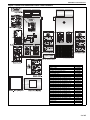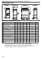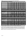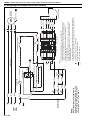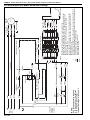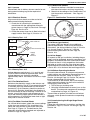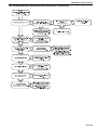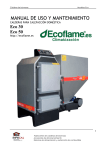
1
FOR YOUR SAFETY
If you smell gas:
1. Open windows.
2. DO NOT try to light any appliance.
3. DO NOT use electrical switches.
4. DO NOT use any telephone in
your building.
5. Extinguish any open flame.
6. Leave the building.
7. Immediately call your local gas
supplier after leaving the building.
Follow the gas supplier’s
instructions.
8. If you cannot reach your gas
supplier, call the Fire Department.
WARNING
Combat
®
Cabinet Heaters
Installation,
Commissioning,
OIL-FIRED:
Model MOB
015 to 0100
Fire Hazard
GAS-FIRED:
Model MGB
015 to 0100
Keep all flammable objects, liquids and
vapours the minimum required
clearances to combustibles away from
heater.
Some objects will catch fire or explode
when placed close to heater.
Failure to follow these instructions can
result in death, injury or property
damage.
WARNING
Improper installation, adjustment, alteration, service
or maintenance can result in death, injury or property
damage. Read the installation, operation and service
manual thoroughly before installing or servicing
this equipment.
Installation must be done by a registered installer/
contractor qualified in the installation and service of
gas/oil-fired heating equipment or your fuel supplier.
© 2013 Roberts-Gordon Europe Limited
Installer
Please take the time to read and understand
these instructions prior to any installation.
Installer must give a copy of this manual to the owner.
Owner
Keep this manual in a safe place in order to provide
your service technician with necessary information.
Roberts-Gordon Europe Limited
Unit A, Kings Hill Business Park
Darlaston Road, Wednesbury
West Midlands,WS10 7SH UK
Telephone: +44 (0)121 506 7700
Fax: +44 (0)121 506 7701
Service Telephone: +44 (0)121 506 7709
Service Fax: +44 (0)121 506 7702
E-mail: [email protected]
E-mail: [email protected]
www.robertsgordon.co.uk
www.rg-inc.com
P/N X523 Rev J 08/13
TABLE OF CONTENTS
SECTION 1: Heater Safety...................................................... 2
1.1 Manpower Requirements ............................................. 2
1.2 Safety Labels and Their Placement ............................. 2
SECTION 2: Installer Responsibility ..................................... 4
2.1 Laminated Wall Plate ................................................... 4
2.2 Corrosive Chemicals.................................................... 4
2.3 National Standards and Applicable Codes .................. 4
SECTION 3: Critical Considerations ..................................... 5
3.1 Basic Information ......................................................... 5
3.2 Location and Suspension ............................................ 5
3.3 Required Clearances to Combustibles......................... 5
3.4 Ventilation .................................................................... 6
3.5 Fuel Supply .................................................................. 6
3.6 Electrical Supply .......................................................... 7
3.7 Flue.............................................................................. 7
SECTION 4: Specifications .................................................... 8
4.1 MGB & MOB Internal Heaters ..................................... 8
4.2 MGB & MOB External Heaters .................................... 9
4.3 Air Outlet and Flue Arrangements ............................. 10
4.4 General Technical Data Table (all models)
Appliance Category II 2H/L 3B/P ..................................... 11
4.5 Technical Data - Ecoflam ON/OFF Burners ............... 11
4.6 Technical Data - Ecoflam 2-Stage Burners ................ 12
4.7 Technical Data - Ecoflam Oil-Fired Burners ............... 13
4.8 Technical Data - Ecoflam 2-Stage Oil Burners........... 14
SECTION 5: Heater Installation............................................ 15
5.1 General ...................................................................... 15
5.2 Handling .................................................................... 15
SECTION 6: Flue Installation ............................................... 17
6.1 Flue Installation.......................................................... 17
6.2 Type B22 Appliance..................................................... 18
6.3 Type C12, C32 & C62 Appliance .................................... 20
SECTION 7: Air Supply......................................................... 22
7.1 Room Sealed Installation ........................................... 22
7.2 Open Flued Installation .............................................. 22
7.3 Building Ventilation ..................................................... 22
7.4 Isolated Equipment Rooms ........................................ 22
SECTION 8: Fuel Pipe Work ................................................. 23
8.1 Connections............................................................... 23
8.2 Fuel Oil Supply .......................................................... 24
SECTION 9: Wiring and Electrical Information................... 27
9.1 Electrical Supply ........................................................ 27
9.2 Remote Controls ........................................................ 27
9.3 Wiring Diagram Gas Models 15-30 (floor standing) ... 28
9.4 Wiring Diagram Oil Models 15-30 (floor standing) ..... 29
9.5 Wiring Diagram Gas Models 15-30
(horizontal mounting)................................................. 30
9.6 Wiring Diagram Oil Models 15-30
(horizontal mounting)................................................. 31
9.7 Wiring Diagram Gas Models 40-50 (floor standing)... 32
9.8 Wiring Diagram Oil Models 40-50 (floor standing) ..... 33
9.9 Wiring Diagram Gas Models 40-50
(horizontal mounting)................................................. 34
9.10 Wiring Diagram Oil Models 40-50
(horizontal mounting)................................................. 35
9.11 Wiring Diagram Gas Models 60-100
(floor standing) .......................................................... 36
9.12 Wiring Diagram Oil Models 60-100
(floor standing) .......................................................... 37
9.13 Wiring Diagram Gas Models 60-100
(horizontal mounting) .................................................38
9.14 Wiring Diagram Oil Models 60-100
(horizontal mounting) .................................................39
SECTION 10: Commissioning ..............................................40
10.1 Pre-Commission Checks ..........................................40
10.2 Commissioning the Single Stage Burner
(gas heaters) ..............................................................41
10.3 Commissioning the Two-Stage (High/Low) Burner
(gas heaters) ..............................................................43
10.4 Motor Starter and Thermal Overload .......................44
10.5 Gas Valves ...............................................................44
10.6 Combustion Testing (all models) ..............................45
10.7 Commissioning the Burner (Oil Heaters)..................45
10.8 Control - Oil-Fired Heaters .......................................45
10.9 Turning Off the Heater (all models) ..........................47
10.10 External Controls ....................................................47
10.11 Instruction to the User ............................................47
SECTION 11: User Instructions............................................48
11.1 User Instructions .......................................................48
11.2 Common User Controls (all models) .........................49
11.3 Lighting Instructions (all models) ..............................49
11.4 Simple Fault Finding (all models)..............................49
SECTION 12: Servicing .........................................................51
12.1 Servicing Instructions...............................................51
12.2 Burner Maintenance.................................................51
12.3 Fan/Motor Assembly Maintenance (all models) .......52
12.4 Heat Exchanger Maintenance ..................................52
12.5 Thermal Insulation ...................................................52
12.6 Maintenance Checklist .............................................53
SECTION 13: Conversion Between Fuels............................55
13.1 General ....................................................................55
13.2 Burner Conversion ...................................................55
SECTION 14: Troubleshooting .............................................56
14.1 General ....................................................................57
14.2 Troubleshooting for Oil Burners (see manufacture’s
instructions) ...............................................................58
14.3 Troubleshooting for Gas Burners (see manufacturer’s
instructions) ...............................................................59
14.4 Troubleshooting for Flame Supervision System .......60
14.5 Troubleshooting for Solenoid Valves Circuit .............61
14.6 Troubleshooting for Main Fan Circuit (1 Ø)...............61
14.7 Troubleshooting for Main Fan (3 Ø)..........................62
SECTION 15: Removal and Replacement Parts..................63
15.1 Burner Components ..............................................63
15.2 Direct On-Line Main Fan Starter and Thermal
Overload Unit (3 Ø) ....................................................63
15.3 Control Circuit Protection..........................................64
15.4 Combination Fan/Limit Thermostat ..........................64
15.5 Main Fan Motor (3 Ø Belt Drive)...............................64
15.6 Main Fan Units .........................................................64
SECTION 16: Spare Parts List..............................................66
16.1 Gas On/Off ...............................................................66
16.2 Gas High/Low...........................................................71
16.3 Oil On/Off .................................................................75
16.4 Oil High/Low.............................................................81
© 2013 Roberts-Gordon Europe Limited
All rights reserved. No part of this work covered by the copyrights herein may be reproduced
or copied in any form or by any means - graphic, electronic, or mechanical, including
photocopying, recording, taping or information storage and retrieval systems - without the
written permission of Roberts-Gordon Europe Limited.
Printed in U.K.
TABLE OF FIGURES
Figure 1: Burner and Combustion Panel Label Placement ....... 3
Figure 2: Installation Clearances and Clearances to
Combustibles ........................................................... 6
Figure 3: Typical Installation of an Gas-Fired Cabinet Heater . 15
Figure 4: Typical Installation of an Oil-Fired Cabinet Heater ... 16
Figure 5: Flue Termination ...................................................... 18
Figure 6: Offset Flues with 135° Bends................................... 18
Figure 7: 90° Horizontal Flue .................................................. 19
Figure 8: Guy Wire .................................................................. 19
Figure 9: Socket Direction (Stainless Steel)............................ 19
Figure 10: Flue and Roof Detail (Stainless Steel) ................... 19
Figure 11: Flue Installation (Models 15 - 100) ........................ 20
Figure 12: Balanced Flue (Vertical)......................................... 20
Figure 13: Balanced Flue (Horizontal)..................................... 21
Figure 14: Gas Connection ..................................................... 24
Figure 15: B. M. Oil Lifter ........................................................ 25
Figure 16: Pressurised System Installation - Duplex System .. 26
Figure 17: Combination Thermostat (all models) .................... 41
Figure 18: Gas-Fired Heater Control Box Sequence............... 43
Figure 19: Gas Train Circuit for Dungs Gas Valves (all models)..
44
Figure 20: Oil-Fired Heaters Control Box Sequence ............... 46
Figure 21: Heater Operating Sequence .................................. 48
Figure 22: Fan/Limit Thermostat ............................................. 49
Figure 23: Belt Tension ........................................................... 52
Figure 24: Combination Fan/Limit Thermostat Parts List ........ 65
Product Approval
1 of 85
COMBAT® CABINET HEATERS INSTALLATION, COMMISSIONING, OPERATION AND SERVICE MANUAL
SECTION 1: HEATER SAFETY
Your Safety Is Important to Us!
This symbol is used throughout the
manual to notify you of possible fire,
electrical or burn hazards. Please pay
special attention when reading and
following the warnings in these sections.
Installation, Service and Annual Inspection of heater
must be done by a registered installer/contractor
qualified in the installation and service of gas/oilfired heating equipment.
Read this manual carefully before installation,
operation, or service of this equipment.
Burner manufacturers manual is also provided to
give detailed instructions on the operation of the
burner. The settings for use of the burner with the
heater are shown in these instructions.
This heater is designed for heating non-residential
indoor spaces. Do not install in residential spaces.
These instructions, the layout drawing, local codes
and ordinances, and applicable standards that apply
to gas piping, electrical wiring, venting, etc., must be
thoroughly understood before proceeding with the
installation.
Protective gear is to be worn during installation,
operation and service. Thin sheet metal parts, such
as the various venting components, have sharp
edges. To prevent injury, the use of work gloves is
recommended.
Before installation, check that the local distribution
conditions, nature of gas and pressure, and
adjustment of the appliance are compatible.
The heater must be applied and operated under the
general concepts of reasonable use and installed
using best building practices.
This appliance is not intended for use by persons
(including children) with reduced physical, sensory
or mental capabilities, or lack of experience and
knowledge, unless they have been given
supervision or instruction concerning use of the
appliance by a person responsible for their safety.
Children should be supervised to ensure that they
do not play with the appliance.
For additional copies of the Installation,
Commissioning, Operation and Service Manual, or
relavant EcoFlame burner and gas train manuals,
please contact Roberts-Gordon Europe Limited.
1.1 Manpower Requirements
To prevent personal injury and damage to the
heater, two persons will be required for installation.
2 of 85
1.2 Safety Labels and Their Placement
Product safety signs or labels should be replaced by
the product user when they are no longer legible.
Contact Roberts-Gordon Europe Limited for
obtaining replacement signs or labels. See Page 3,
Figure 1.
SECTION 1: HEATER SAFETY
Figure 1: Burner and Combustion Panel Label Placement
Description
Logo Label
Address Label
Rating Plate Label
Electrical Shock Hazard Label
Severe Injury Hazard Label
Burn Hazard Label
Fire Hazard Label
Lighting Instruction Label
Wiring Diagram Models 15-30 Gas, Floor
Wiring Diagram Models 40-50 Gas, Floor
Wiring Diagram Models 60-100 Gas, Floor
Wiring Diagram Models 15-30 Gas, Horz.
Wiring Diagram Models 40-50 Gas, Horz.
Wiring Diagram Models 60-100 Gas, Horz.
Wiring Diagram Models 15-30 Oil, Floor
Wiring Diagram Models 40-50 Oil, Floor
Wiring Diagram Models 60-100 Oil, Floor
Wiring Diagram Models 15-30 Oil, Horz.
Wiring Diagram Models 40-50 Oil, Horz.
Wiring Diagram Models 60-100 Oil, Horz.
Wiring Diagram Models 40-50 Gas 1Ø Belt
Wiring Diagram Models 40-50 Oil 1Ø Belt
Wiring Diagram Models 60-100 Gas Star
Wiring Diagram Models 60-100 Oil Star
Plastic Pouch
Burner Lockout Label
Part Number
91040030
91040006
91040001
91008001
91070002
91070004
91070006
91040129
91040140
91040141
91040142
91040143
91040144
91040145
91040146
91040147
91040148
91040149
91040150
91040151
91040152
91040153
91040154
91040155
90911300
91040058
3 of 85
COMBAT® CABINET HEATERS INSTALLATION, COMMISSIONING, OPERATION AND SERVICE MANUAL
SECTION 2: INSTALLER RESPONSIBILITY
WARNING
Explosion Hazard
2.2 Corrosive Chemicals
CAUTION
Product Damage Hazard
Equipment must have access to
uncontaminated air at all times.
Do not use heater in area containing
corrosive chemicals.
Failure to follow these instructions can result
in death, injury or property damage.
Refer to appropriate Material Safety Data
Sheets (MSDS).
• To install the heater, as well as the fuel and
electrical supplies, in accordance with applicable
specifications and codes. Roberts-Gordon
Europe Limited recommends the installer contact a local building inspector, Fire Officer or
insurance company for guidance.
• To use the information given in this manual
together with the local and national codes to
perform the installation.
• To install the heater in accordance with the
clearances to combustibles of this heater.
• To furnish all needed materials not furnished
as standard equipment.
• To plan location of supports, flues and air
intakes.
• To provide access to burners for servicing.
• To provide the owner with a copy of this
installation, commissioning, operation and
service manual.
• To never use heater as support for ladder or
other access equipment and never hang or
suspend anything from heater.
• To ensure that there is sufficient ventilation in the
area to comply with the requirements of
all relevant local and national codes.
• To ensure the heater is placed in an approved
application.
2.1 Laminated Wall Plate
A laminated wall plate is available for the heater as a
permanent reminder of the safety instructions and
the importance of the required clearances to
combustibles. Affix the plate by peeling off the
backing of the adhesive strips on the rear surface
and position the plate on a wall near the heater (e.g.
thermostat or ROBERTS GORDON® Controller).
A copy of the wall plate (P/N 91040095) is illustrated
on the back cover. Know your model number and
installed configuration. Model number and installed
configuration are found on the burner and in the
Installation, Commissioning, Operation and Service
Manual. Write the largest clearance dimensions with
permanent ink according to your model number and
configuration in the open spaces on the plate.
4 of 85
Failure to follow these instructions can result
in product damage.
Roberts-Gordon Europe Limited cannot be
responsible for ensuring that all appropriate safety
measures are undertaken prior to installation; this is
entirely the responsibility of the installer. It is
essential that the contractor, the sub-contractor, or
the owner identifies the presence of combustible
materials, corrosive chemicals or halogenated
hydrocarbons* anywhere in the premises.
* Halogenated Hydrocarbons are a family of chemical
compounds characterized by the presence of halogen
elements (fluorine, chlorine, bromine, etc.). These compounds are frequently used in refrigerants, cleaning
agents, solvents, etc. If these compounds enter the air
supply of the burner, the lifespan of the heater components will be greatly reduced. Warranty will be invalid if
the heater is exposed to halogenated hydrocarbons.
2.3 National Standards and Applicable Codes
All appliances must be installed in accordance with
the latest revision of applicable standards and local
and national codes. This refers also to the electric,
gas and venting installation. Note: Additional
standards for installations in public garages, aircraft
hangars, etc. may be applicable.
The main relevant regulations for installation within
the UK are:
• Gas safety (installation and use) regulations,
1984 and amendments - 1996.
• BS6230 - Specification for the installation of gas
fired forced convection air heaters for commercial and industrial space heating of rated input
exceeding 60 kW. (This standard also applies to
oil-fired heaters, except for the fuel supply).
• BS6230 - Parts 2 & 3, fire precautions in the
design and construction of buildings.
• BS6891 - Low pressure installation pipes.
• BS5410 - Codes of practice for oil firing. Part 2
installation of 44 kW and above output capacity
for space heaters, hot water and steam supply
purposes.
• Institute of Gas Engineers document IGE/UP/2.
• Building regulations.
• IEE regulations.
• Health and safety at work acts.
• Requirements of local authority, fire officer and
insurance company.
SECTION 3: CRITICAL CONSIDERATIONS
SECTION 3: CRITICAL CONSIDERATIONS
combustibles are not indicated, then installation
clearances apply.
Check the clearances on each heater for the model
heater being installed to make sure the product is
suitable for your application and the clearances are
maintained. Read and follow the safety guidelines
below:
• Keep petrol or other combustible materials
including flammable objects, liquids, dust or
vapours away from this heater or any other appliFire Hazard
ance.
Keep all flammable objects, liquids and
• Do not spray aerosols in the vicinity of this applivapours the minimum required clearances to
combustibles away from heater.
ance.
• The stated clearances to combustibles repreSome objects will catch fire or explode when
sents a surface temperature of 50° C (90° F)
placed close to heater.
above room temperature. Building materials with
Failure to follow these instructions can result
a low heat tolerance (such as plastics, vinyl sidin death, injury or property damage.
ing, canvas, tri-ply, etc) may be subject to degradation at lower temperatures. It is the installer’s
3.1 Basic Information
responsibility to assure that adjacent materials
Cabinet heaters are supplied with burners suitable
are protected from degradation.
for on/off operation as standard. As an option, twostage (High/Low) operation is available for gas and
• Maintain clearances from heat sensitive equipoil-fired burners.
ment and workstations.
• Maintain clearances from vehicles parked below
3.2 Location and Suspension
the heater.
All models:
• Maintain clearances from swinging and over• Must be installed indoors within the heated
head doors, overhead cranes, vehicle lifts, partispace. Special versions are available for installations, storage racks, hoists, building
tion outdoors.
construction, etc.
• Must be installed for floor standing vertical
• In locations used for the storage of combustible
installation.
materials, signs must be posted to specify the
• Must be installed in a manner which allows all
maximum permissible stacking height to mainthe upper panels and either of the lower side
tain required clearances from the heater to the
panels to be removed to provide access to all
combustibles. Signs must be posted adjacent to
serviceable components.
the heater thermostat. In the absence of a ther• Must be placed on a firm, level, non-combustible
mostat, signs must be posted in a conspicuous
surface that can support its weight. See Page 8,
location.
Section 4.1 for weight details.
• Consult local Building Inspector, Fire Insurance
• Special versions supplied with steel channels to
Carrier or other authorities for approval of prosupport the heater are available and may be
posed installation when there is a possibility of
mounted horizontally. When installed horizonexposure to combustible airborne materials or
tally, the heater will normally lie on its left side
vapours.
when viewed from the burner. The same clearances and comments on panels must be used,
• Hang heater in accordance to minimum suspenexcept for the side the heater lies on.
sion requirements. Consult manufacturer.
• Affix the tag on a wall near the heater.
3.3 Required Clearances to Combustibles
Clearances are the required distances that
combustible objects must be away from the heater
to prevent fire hazards. Caution should be used
when running the system near combustibles.
Combustibles are materials, which may catch on fire
and include common items such as wood, paper,
rubber, fabric, etc. Maintain clearances to
combustibles at all times for safety.
Clearances around the heater and flue must be as
indicated on Page 6, Figure 2 to ensure access for
servicing, and correct operation. If clearances to
5 of 85
WARNING
COMBAT® CABINET HEATERS INSTALLATION, COMMISSIONING, OPERATION AND SERVICE MANUAL
Figure 2: Installation Clearances and Clearances to Combustibles
.6 m (2')
*.6 m (2')
4 m (13.2')
.6 m
(2')
*.6 m
(2')
*.6 m
(2')
The flue pipe must have clearance from combustibles by 5 cm.
If installed where individuals can come in contact with the pressure relief door or other hot components,
adequate guarding must be provided.
All distances are minimum clearance requirements for service access, air flow and safety.
*A service clearance of 1 m is required on one side to allow for fan replacement.
3.4 Ventilation
3.5 Fuel Supply
WARNING
Carbon Monoxide Hazard
Heaters may be installed vented or unvented.
Vented heaters must be vented outdoors.
Unvented heaters must be installed in buildings
with ventilation rates as per section 7.
Failure to follow these instructions can result in
death or injury.
It is important to ensure that there is adequate air
circulation around the heater to supply air for
combustion, ventilation and distribution in
accordance with local and national codes.
6 of 85
It is important that the fuel supply pipe is sized
correctly to provide the inlet pressure as stated on
the heater data plate. The gas/oil supply pipe and
electrical connections must not support any of the
heater's weight.
SECTION 3: CRITICAL CONSIDERATIONS
3.6 Electrical Supply
DANGER
Electrical Shock Hazard
Disconnect electric before service.
Heater must be properly grounded.
Failure to follow these instructions can result
in death or electrical shock.
A permanent 230 V, 50 Hz, 1 Ø is required on
models 15 to 30 and 400 V, 50 Hz, 3 Ø and neutral
required on models 40 to 100 (special version MGB
and MOB 040 and 050 models are available as belt
drive). The heater also requires suitable energy
controls in accordance with Page 27, Section 9.
ON/OFF control, temperature control, time control,
and frost protection are available as a remote
control, which needs to be site wired for proper
operation of the heater. Alternatively, any remote
energy controls may be used which must be wired in
accordance with Page 28, Section 9.3 through Page
39, Section 9.14.
3.7 Flue
Choose heater siting to allow for the proper location
of the flue. Each heater must be fitted with an
individual and correctly sized sealed flue system.
See Page 17, Section 6.
No other appliance may be connected to the flue.
For room sealed installation, the air intake must be
the same size sealed system and the flue/air intake
must terminate at an approved concentric wall or
roof terminal.
7 of 85
COMBAT® CABINET HEATERS INSTALLATION, COMMISSIONING, OPERATION AND SERVICE MANUAL
SECTION 4: SPECIFICATIONS
4.1 MGB & MOB Internal Heaters
Front View
(all models)
Rear View
(all models)
Side View
(Models 060 - 0100)
Side View
(Models 015 - 050)
D
D
E C
G
A
70
38
G
F
B
38
70
38
F
B
38
Dimension Data - MGB & MOB Internal Heaters
Model 015/020
A
Width
B
Depth, Cabinet Only
C
Height, Cabinet Only
D
Depth, Overall
E
Height, Including Heads
F
Left/Right Air Inlet Spigot - Depth
G
Left/Right Air Inlet Spigot - Height
H
Rear Air Inlet Spigot - Depth
J
Rear Air Inlet Spigot - Height
Flue Diameter*
Flue Length**
Weight
mm
(in)
mm
(in)
mm
(in)
mm
(in)
mm
(in)
mm
(in)
mm
(in)
mm
(in)
mm
(in)
mm
(in)
m
(ft)
kg
(lbs)
723
28.5
860
33.9
1778
70
1267
50
2007
79
781
31
457
18
648
26
361
14
100
4
8
27
200
441
030
040
050
060/070/080
0100
723
28.5
860
33.9
1778
70
1267
50
2083
82
781
31
457
18
648
26
361
14
130
5
8
27
200
441
853
33.6
860
33.9
1956
77
1337
53
2261
89
781
31
560
22
781
31
446
18
130
5
8
27
245
541
857
33.7
1015
40
1956
77
1496
59
2261
89
940
37
560
22
781
31
446
18
130
5
8
27
270
596
1016
40
1676
66
1956
77
2156
85
2261
89
1600
63
560
22
1016
40
1994
79
1956
77
2496
98
2261
89
1918
76
559
22
NA
NA
NA
NA
229
9
229
9
NA
NA
440
970
530
1170
NOTES: Horizontal cabinet heaters are designed to lie on their left side as standard.
For vertical models, add 54 mm (2 in) to the right side of the cabinet for the fan/limit thermostat.
For horizontal models, add 54 mm (2 in) to the top of the cabinet for the fan/limit thermostat.
*All MOB heaters must be connected to a suitable flue constructed of single wall stainless steel.
*MGB 15-50 heaters must be connected to a suitable flue constructed of single wall aluminium or stainless steel.
** Maximum flue length between heater and flue terminal (horizontal only).
8 of 85
SECTION 4: SPECIFICATIONS
4.2 MGB & MOB External Heaters
Front View
Rear View
Side View
275
F
H
D
G
P
J
50
C
C
L
M
A
70
38
N
B
108
38
38
E
38
K
A
Dimension Data - MGB & MOB External Heaters
A
Width
B
Depth, Cabinet Only
C
Height, Cabinet Only
D
Depth Overall
E
External Heater Housing
F
Width Overall
G
Air Outlet Spigot - Depth
H
Air Outlet Spigot - Width
J
Flue Diameter
K
Rear Return/Fresh Air Inlet - Width
L
Rear Return/Fresh Air Inlet - Height
M
Left/Right Return Fresh Air Inlet - Height
N
Left/Right Return Fresh Air Inlet - Width
P
Rear of Heater to Air Outlet Spigot*
Model
015/020/030
040
050
060/070/080
0100
mm
(in)
mm
(in)
mm
(in)
mm
(in)
mm
(in)
mm
(in)
mm
(in)
mm
(in)
mm
(in)
mm
(in)
mm
(in)
mm
(in)
mm
(in)
mm
(in)
723
28.5
860
33.9
1778
70
1396
55
373
15
840
33
476
19
648
26
178
7
648
26
178
7
457
18
781
31
401
16
853
33.6
860
33.9
1956
77
1498
59
474
19
973
38
476
19
781
31
178
7
781
31
178
7
560
22
781
31
401
16
857
33.7
1015
40
1956
77
1657
65
474
19
973
38
610
24
781
31
178
7
781
31
178
7
560
22
940
37
426
17
1016
40
1676
66
1956
77
2483
98
639
25
1132
45
1238
49
940
37
229
9
1016
40
1994
79
1956
77
2800
110
639
25
1132
45
1524
60
940
37
229
9
NA
NA
229
9
560
22
1600
63
96
4
229
9
560
22
1918
76
96
4
NOTE: *For Models 060-0100, the circular flue spigot is at the front of the heater, with the rectangular air outlet spigot at the rear.
COMBAT® external cabinet heaters are designed to be sited externally, with heat ducted into the building. These models
are fitted with a special metal rain drip cover, and all cabinet joints are silicone sealed to ensure that the heaters are
weatherproof.
9 of 85
COMBAT® CABINET HEATERS INSTALLATION, COMMISSIONING, OPERATION AND SERVICE MANUAL
4.3 Air Outlet and Flue Arrangements
4.3.1 Vertical and Horizontal Heaters - Free Blowing (top view)
040
030
015/020
165
165
0100
060/070/080
050
229
203
184
284
NOTE: Models 015-020 are fitted with 229 mm (9") diameter discharge heads as standard.
Models 030-0100 are fitted with 356 mm (14") diameter discharge heads as standard.
4.3.2 Vertical and Horizontal Heaters - Air Outlet Spigots (top view)
015/020/030
050
040
100
343
L
K
38
38
38
368
L
38
K
38
38
38
100
100
343
060/070/080
K
100
K
38
0100
K
38
38
100
L
L
38
38
38
38
38
L
400
432
Outlet Spigot Dimensions
K
Spigot width
L
Spigot Depth
10 of 85
Model
015/020/030
040
050
060/070/080
0100
mm
(in)
mm
(in)
648
26
476
19
781
31
476
19
781
31
610
24
940
37
1238
49
940
37
1524
60
SECTION 4: SPECIFICATIONS
4.4 General Technical Data Table (all models)
Appliance Category II 2H/L 3B/P
Model
015
020
030
Electrical Supply*
Main Fan Motor Type
Motor Size
(kW)
Motor Pulley
(PCD)
NA
Fan Pulley
(PCD)
NA
Start Current
Run Current
Airflow
Free Blowing
040
050
230 V / 50 Hz / 1 Ø
Direct Drive
0.75
(Amps)
(Amps)
(m3/h)
(ft3/min)
24
5.3
3398
2000
24
5.3
3398
2000
2.2
28
6.3
5097
3000
21
6.2
6796
4000
21
6.2
8495
5000
060
070
080
0100
400 V / 50 Hz / 3 Ø
Belt Drive
1.5
2.2
4.0
2Ax
2Ax
2
A
x
95
mm
80 mm
106 mm
2Ax
2Ax
2Ax
2Ax
180 mm 180 mm 180 mm 180 mm
10.2
30
30
35
3.5
5.1
5.1
9.6
11044
12443
12443
17330
6500
7500
7500
10200
NOTE: *Models 40 & 50 are available with 230 V 1 Ø electrical supply as an extra cost option.
A permanent uninterrupted electrical supply is required for all models.
When reading the following data tables, ensure that you are using the correct table for the burner and gas
valve installed. The data tables include a burner reference letter that can be found on the heater data plate.
Refer to the burner manufacturer’s instructions and the specific instructions supplement where applicable.
The burner settings shown in the instructions must be used for burner settings.
4.5 Technical Data - Ecoflam ON/OFF Burners
Model
Gross Heat Input
Net Heat Input
Heat Output
Pressure Switch
Setting
Gas Connection
(kW)
(Btu/h) x (1000)
(kW)
(Btu/h) x (1000)
(kW)
(Btu/h) x (1000)
015
020
030
040
050
060
070
080
0100
55.5
189.4
50.0
170.6
47.4
161.7
73.3
250.1
66.0
225.2
61.2
208.8
93.2
318.0
84.0
286.6
77.1
263.0
129.9
443.2
117.0
399.2
107.4
366.5
162.0
552.7
146.0
498.2
134.5
458.9
208.0
709.7
187.4
639.4
171.5
585.2
242.0
825.7
218.0
743.8
200.8
685.1
275.2
939.0
248.0
846.2
230.4
786.1
348.5
1189.1
314.0
1071.4
289.5
987.8
(mbar)
(in)
4.8
1/2
3/4
1
1 1/4
Natural Gas (G20) Data - Inlet Pressure 20 mbar (7.8 in WG) Min 17 mbar (6.8 in WG) Max 25 mbar (10 in WG)
Main Burner Gas
Pressure
mbar
Gas Rate
(m3/h)
(ft3/h)
Burner Type
Burner Head
Burner Head Setting
Air Setting
(mm)
Air Damper Position
5.5
7
8.3
5.3
7.0
8.9
12.4
187
247
314
438
Max Gas Max Gas Max Gas Max Gas
70
105
105
170
TL
TC
TC
TC
1.5
1.5
2.8
0.8
3
MB-DLE
403
Valve Type Main Gas
4.8
3
14
MB-DLE 405
5
8.3
8
8.5
15.4
546
Max Gas
170
TC
2
19.8
701
Max Gas
250
TC
3.5
23.1
816
Max Gas
250
TC
5
5
4.5
5
MB-ZRDLE 407
MB-ZRDLE 410
8.8
10.0
26.2
33.2
928
1175
Max Gas Max Gas
350
350
TC/TL
TC/TL
1
1.5
2.3
4
MB-ZRDLE 412
LPG Gas Propane (G31) Data - Inlet Pressure 37 mbar (14.6 in WG) Min 25 mbar (10 in WG) Max 45 mbar (18 in WG)
Main Burner Gas
Pressure
Gas Rate
Main Gas Orifice
mbar
5.4
3.9
4.8
9.4
8.3
8.5
8.4
7.3
10.1
(m3/h)
(kg/h)
(mm dia)
2.1
3.9
8.5
Max Gas
70
TL
1
2.8
5.2
10.0
3.5
6.5
10.0
4.9
9.1
14.5
6.1
11.3
14.5
7.8
14.4
14.5
9.1
16.9
14.5
10.4
19.3
14.5
13.1
24.3
3
Burner Type
Burner Head
Burner Head Setting
Air Setting
Valve Type Main Gas
(mm)
Air Damper Position
MB-DLE
403
Max Gas 105
Max Gas 170
Max Gas 250
TC
1
TC
2
TC
0
TC
1.8
TC
2.8
TC
4.2
TC/TL
1
TC/TL
1.5
3
14
5
5
4.5
5
2.3
4
MB-DLE 405
MB-ZRDLE 407
MB-ZRDLE 410
Max Gas 350
MB-ZRDLE 412
NOTE: For adjustment of head setting, see Ecoflam Instructions.
11 of 85
COMBAT® CABINET HEATERS INSTALLATION, COMMISSIONING, OPERATION AND SERVICE MANUAL
4.6 Technical Data - Ecoflam 2-Stage Burners
Model
Maximum Gross Heat Input
Maximum Net Heat Input
Minimum Gross Heat Input
Minimum Net Heat Input
Maximum Heat Output
Minimum Heat Output
Pressure Switch Setting
Gas Connection
(kW)
(Btu/h) x (1000)
(kW)
(Btu/h) x (1000)
(kW)
(Btu/h) x (1000)
(kW)
(Btu/h) x (1000)
(kW)
(Btu/h) x (1000)
(kW)
(Btu/h) x (1000)
(mbar)
(in)
020
030
040
050
060
070
080
0100
73.3
250.1
66.0
225.2
51.3
175.0
46.2
157.6
61.2
208.8
43
147
93.2
318.0
84.0
286.6
65.2
222.5
58.8
200.6
77.1
263.0
55
188
129.9
443.2
117.0
399.2
90.9
310.2
81.9
279.5
107.4
366.5
77
263
162.0
552.7
146.0
498.2
113.4
386.9
102.2
348.7
134.5
458.9
94
321
208.0
709.7
187.4
639.4
145.6
496.8
131.2
447.7
171.5
585.2
124
423
242.0
825.7
218.0
743.8
169.4
578.0
152.6
520.7
200.8
685.1
144
491
275.2
939.0
248.0
846.2
192.6
657.2
173.6
592.3
230.4
786.1
161
549
348.5
1189.1
314.0
1071.4
244.0
832.5
219.8
750.0
289.5
987.8
205
699
4.8
1/2
3/4"
1
1 1/4
Natural Gas (G20) Data - Inlet Pressure 20 mbar (7.8 in WG) Min 17 mbar (6.8 in WG) Max 25 mbar (10 in WG)
Main Burner Gas Pressure
Min. Burner Gas Pressure
Maximum Gas Rate
Minimum Gas Rate
Burner Type
Burner Head
Burner Head Setting
Low Flame Air Orange Cam
High Flame Air Red Cam
Valve Type Main Gas
(mbar)
(mbar)
(m3/h)
(ft3/h)
(m3/h)
(ft3/h)
(number)
**
**
5.4
6.8
3.3
2.8
7.0
8.9
247
314
5.4
5.6
190.7
197.8
Max Gas 120
TC
TC
1
1
30°
36°
73°
MB-ZRDLE 405
8.6
9
3.5
4
12.4
15.4
438
544
7.5
9.6
264.9
339.0
Max Gas 170
TC
TC
1
1.5
1
1.5
2.5
5
MB-ZRDLE 407
8.5
12.5
4.8
7.5
19.8
23.1
699
816
14.8
17.9
522.7
632.1
Max Gas 250
TL
TL
3.2
5
1.8
1.9
5
4
MB-ZRDLE 410
8
10.2
4.5
5.6
26.2
33.2
925
1172
20.2
25.2
713.4
889.9
Max Gas 350
TC/TL
TC/TL
1
1.5 / 1.8
1.7
1.5
2.2
1.8
MB-ZRDLE 412
LPG Gas Propane (G31) Data - Inlet Pressure 37 mbar (14.6 in WG) Min 25 mbar (10 in WG) Max 45 mbar (18 in WG)
Main Burner Gas Pressure
Min. Burner Gas Pressure
Maximum Gas Rate
Minimum Gas Rate
Main Gas Orifice
Burner Type
Burner Head
Burner Head Setting
Low Flame Air Orange Cam
High Flame Air Red Cam
Valve Type Main Gas
(mbar)
(mbar)
(m3/h)
(kg/h)
(m3/h)
(kg/h)
(mm dia)
(mm)
**
**
2.7
1.9
2.8
5.1
1.9
3.5
4.4
1.3
3.5
6.5
1.9
3.5
10.0
Max Gas 120
TC
TC
1
1
30°
25°
35°
55°
MB-ZRDLE 405
9.3
4.8
4.9
9.1
3.3
6.1
8.4
3.9
6.1
11.3
4.1
7.6
Max Gas 170
TC
TC
0
1.7
1.5
1
3
5
MB-ZRDLE 407
8.4
8.3
3.9
4.8
7.8
9.1
14.5
16.9
6.2
6.6
11.4
12.2
14.5
Max Gas 250
TL
TL
4.2
2.7
1.9
1.9
5
5
MB-ZRDLE 410
8
7.4
10.4
19.2
6.5
12.0
10.1
5.3
13.1
24.3
10.2
19.0
NA
Max Gas 350
TC/TL
TC/TL
1
1.5
2
1.5
2.1
5
MB-ZRDLE 412
NOTE: The air setting is a guide only. The final setting is subject to combustion testing.
When setting the minimum firing rate, a check must be made following the setting of the burner combustion.
The check is made by running the heater on low fire for a minimum of 15 minutes at the full transport air
rate and at typical ambient conditions. During the test, check that the flue gas temperature does not fall
below 125° C (257° F). Should the flue gas temperature fall below 100° C (212° F), then the low fire gas
setting must be increased to a value that will achieve 125° C (257° F) flue gas temperature; otherwise
condensation may form in the heat exchanger and flue, causing rapid corrosion and short operational life.
NOTE: For adjustment of head setting, see Ecoflam Instructions.
12 of 85
SECTION 4: SPECIFICATIONS
4.7 Technical Data - Ecoflam Oil-Fired Burners
Model
Gross Heat Input
Heat Output
(kW)
(Btu/h) x (1000)
(kW)
(Btu/h) x (1000)
Burner Type
Oil Pump Connections
015
020
030
040
050
060
070
080
0100
55.5
189.4
47.4
161.8
MAX 8
73.3
250.1
61.2
208.9
MAX 8
93.2
318.0
78.4
267.4
MAX 12
129.9
443.2
110.2
375.9
MAX 15
162.0
552.7
134.5
458.8
MAX 15
3/8
208.0
709.7
177.7
606.5
MAX 20
242.0
825.7
205.3
700.3
MAX 20
275.2
939.0
230.4
786.2
MAX 30
348.5
1189.1
293.4
1001.0
MAX 35
1.1
1.35
1.75
60°H
2.25
3
(in)
Light Fuel Oil (Gas Oil) Data
Nozzle Size
Angle & Type
Make
Head Setting
Air Setting
Burner Fuel Pressure
Fuel Consumption
Maximum Oil Pressure to
Pump Inlet
*US (gal/h)
(number)
(number)
(Bar)
(lbf/in2)
(L/h)
*UK (gal/h)
(Bar)
(lbf/in2)
0
.45 (1/2)
10.6
154
5.3
1.17
1
1.4
13
189
7.0
1.55
0.5
4
12.5
181
8.9
1.96
0
2
15.5
225
12.4
2.73
*US (gal/h)
1.25
1.65
2.25
3
4.5
60°B
Danfoss
0
1.5
2.5
2.3
14
11
203
160
15.6
20.0
3.43
4.4
2
2.9
5
5.5
2.5
60°S
60°B
60°B
1.5
3
10.3
149
23.2
5.1
1.5
4.5
10.3
149
26.4
5.8
1.5
3
12
174
30.56
6.72
5.5
6
Kerosene Data
Nozzle Size
Angle & Type
Make
Head Setting
Air Setting
Burner Fuel Pressure
Fuel Consumption
3.5
60°EH
5
60°B
60°ES
60°B
5.5
60°B
Danfoss
(number)
(number)
(Bar)
(lbf/in2)
(L/h)
*UK (gal/h)
0
.45 (1/2)
8.6
125
5.5
1.2
1
1.4
9
131
7.2
1.6
0.5
4
8.1
117
9.2
2.0
0
2
9.5
138
12.8
2.8
0
1.5
1.5
1.5
2.5
7 / 10
102 / 145
16.1
3.5
2.3
9.5
138
20.6
4.5
3
8.5
123
23.9
5.3
4.5
9.5
138
27.2
6.0
1.5
3
8.5
123
31.5
6.9
NOTE: For adjustment of head setting, see Ecoflam Instructions.
* Nozzle sizes are quoted in US gal/h. Fuel consumption is quoted in imperial gal/h.
13 of 85
COMBAT® CABINET HEATERS INSTALLATION, COMMISSIONING, OPERATION AND SERVICE MANUAL
4.8 Technical Data - Ecoflam 2-Stage Oil Burners
Model
Maximum Gross Heat Input
Maximum Net Heat Input
Minimum Gross Heat Input
Minimum Net Heat Input
Maximum Heat Output
Minimum Heat Output
(kW)
(Btu/h) x (1000)
(kW)
(Btu/h) x (1000)
(kW)
(Btu/h) x (1000)
(kW)
(Btu/h) x (1000)
(kW)
(Btu/h) x (1000)
(kW)
(Btu/h) x (1000)
030
040
050
060
070
080
0100
93.2
318.0
84.0
286.6
65.2
222.5
58.8
200.6
77.1
263.0
55
188
129.9
443.2
117.0
399.2
90.9
310.2
81.9
279.5
107.4
366.5
77
263
162.0
552.7
146.0
498.2
113.4
386.9
102.2
348.7
134.5
458.9
94
321
208.0
709.7
187.4
639.4
145.6
496.8
131.2
447.7
171.5
585.2
124
423
242.0
825.7
218.0
743.8
169.4
578.0
152.6
520.7
200.8
685.1
144
491
275.2
939.0
248.0
846.2
192.6
657.2
173.6
592.3
230.4
786.1
161
549
348.5
1189.1
314.0
1071.4
244.0
832.5
219.8
750.0
289.5
987.8
205
699
MAX 12
MAX 15
MAX 15
1.5
2.25
3
Light Fuel Oil (Gas Oil) Data
Burner Type
Oil Pump Connection
Nozzle Size
US (gal/h)
Angle & Type
Make
Head Setting
Low Air Setting
High Air Setting
Burner Fuel Pressure
Low Fuel Consumption
High Fuel Consumption
Maximum Pressure to Pump inlet
60° H
number
number
number
Bar
lbf/in^2
L/h
UK (gal/h)
L/h
UK (gal/h)
Bar
lbf/in^2
60° B
0.5
3.8
2
16 / 10
232.1 /
145.0
7
1.5
8.9
2.0
0
1.5
2
7 / 15.5
101.5 /
224.8
8.5
1.9
12.4
2.7
0
1.9
2.5
15 / 8
217.6 /
116.0
12.9
2.8
15.6
3.4
1.75
3.00
3.50
MAX 25
MAX 25
MAX 25 MAX 35
3/8
2.75 / 1.5 3.00 / 2.00 3.50 / 2.00 4.50 / 2.50
60° B / 60°
60° B
60° B
60° B
H
Danfoss
1
1.5
3.5
1.5
1.6
2.1
1.8
1.5
2.5
4.5
5
3
11
11
12
12
159.5
159.5
174.0
174.0
12.7
2.8
20
4.4
2
2.9
14.3
3.1
23.3
5.1
17
3.7
26.4
5.8
21.1
4.6
33.5
7.4
Kerosene Data
Nozzle Size
Angle & Type
Make
Head Setting
Low Air Setting
High Air Setting
Burner Fuel Pressure
Low Fuel Consumption
High Fuel Consumption
14 of 85
*US (gal/h)
3.00 / 2.00 3.50 / 2.50 4.00 / 2.50 5.50 / 3.00
60°EH
(number)
(number)
(number)
(Bar)
(lbf/in2)
(L/h)
*UK (gal/h)
(L/h)
*UK (gal/h)
0.5
3.8
2
7 / 12
101.5 /
174.0
5.5
1.2
9.2
2.0
0
1.5
2
7 / 9.5
101.5 /
137.8
7.2
1.6
12.8
2.8
60°B
0
1.9
2.5
Danfoss
1
1.6
2.5
1.5
3.5
1.5
2.1
4.5
1.8
5
1.5
3
10
145.0
9.5
137.8
8.5
123.3
10
145.0
8.5
123.3
9.2
2.0
16.1
3.5
12.8
2.8
20.6
4.5
16.1
3.5
24.0
5.3
20.6
4.5
27.2
6.0
23.9
5.3
34.5
7.6
SECTION 5: HEATER INSTALLATION
SECTION 5: HEATER INSTALLATION
WARNING
Crush Hazard
Use proper lifting
equipment and
practices.
Falling Hazard
Use proper safety
equipment and practices to avoid falling.
Severe Injury Hazard
Cut/Pinch Hazard
Use proper lifting
practices and equipment.
Wear protective gear
during installation,
operation and
service.
Equipment and
accessories are
heavy.
Edges are sharp.
Failure to follow these instructions can result in death, injury or property damage.
5.1 General
Heaters are designed for floor standing vertical
installation. Special versions supplied with steel
channels to support the heater are available and
may be mounted horizontally. When installed
horizontally, the heater will normally lie on its left
side when viewed from the burner. The heater
should be placed on a firm, level, non-combustible
surface that can support its weight. See Page 8,
Section 4.1 for weight details.
5.2 Handling
All cabinet heaters are supplied with an integral
pallet and shrink wrapped. Remove pallet before
installing the heater.
Figure 3: Typical Installation of an Gas-Fired Cabinet Heater
*100 mm (4") and 150 mm (6") flue use stainless steel or aluminium flue pipe.
** 229 (9") mm flue use stainless steel single wall flue pipe only.
15 of 85
COMBAT® CABINET HEATERS INSTALLATION, COMMISSIONING, OPERATION AND SERVICE MANUAL
Figure 4: Typical Installation of an Oil-Fired Cabinet Heater
*Only single wall stainless steel flue is to be used on oil-fired cabinet heaters.
16 of 85
SECTION 6: FLUE INSTALLATION
SECTION 6: FLUE INSTALLATION
6.1 Flue Installation
WARNING
Carbon Monoxide Hazard
Heater must be vented.
Heater must be installed according to the
installation manual.
Failure to follow these instructions can result
in death or injury.
WARNING
Fire Hazard
Keep all flammable objects, liquids and
vapours the minimum required clearances to
combustibles away from heater.
Some objects will catch fire or explode when
placed close to heater.
Failure to follow these instructions can result
in death, injury or property damage.
WARNING
18, Figure 5 through Page 21, Figure 13. The joints
between the flue and the roof or wall must be
properly sealed. If the flue passes through a wall or
ceiling of combustible material it must be enclosed
by a sleeve of non-combustible material and be
separated from the sleeve by at least a 25 mm (1")
air gap.
For double walled flue pipe conforming to BS 715,
the 25 mm (1") separation distance should be
measured from the outside surface of the inner liner.
For double wall flue pipe conforming to BS 4543-2
and 3, the external skin and air gap constitutes
insulation to a standard where no extra clearances
to combustibles material is required other than
normal installation tolerances.
Flues must be adequately supported so that the
heater does not bear the weight of the flue.
For straight and offset flue termination, See Page
18, Figure 5 and Figure 6.
Horizontal Flue Installation
Horizontal flue should be fitted ensuring a slight
gradient approximately 2° towards the terminal.
Where condensation is likely, traps should be
included to encourage the condensate to flow freely
to a point from which it may be released, preferably
into a gully. Condensate must not be allowed to
drain back into the heater as this could result in
corrosion and damage.
The condensate pipe from the flue to the disposal
point must be made from corrosion resistant pipe of
not less than 25 mm (1") internal diameter.
90° bends and horizontal pipe must not be used
in flues except for the immediate connection to a
room-sealed heater [1 m (3.5') max]. 135° bends
are used to offset the flue as on Page 18, Figure 6.
If condensation is likely to occur in the flue, then
provision should be made for drainage.
When designing the flue system, the prevention of
the formation and entrapment of condensation must
be a key consideration.
Only single wall stainless steel flue is to be used
on oil-fired cabinet heaters.
Cut/Pinch Hazard
Wear protective gear during installation,
operation and service.
Edges are sharp.
Failure to follow these instructions can result
in injury.
The flue must terminate outside of the building.
Flues and air intakes must be a fully sealed system
and correctly sized for the model. See Page 8,
Section 4.1. Flues should be assembled as on Page
17 of 85
COMBAT® CABINET HEATERS INSTALLATION, COMMISSIONING, OPERATION AND SERVICE MANUAL
Figure 6: Offset Flues with 135° Bends
Figure 5: Flue Termination
Description
Flue Adapter (100 mm)
Flue Adapter (130 mm)
Part Number
90501018K
90501019K
6.2 Type B22 Appliance
The flue must terminate outside the building and be
fitted with a low resistance terminal.
See Page 15, Figure 3 through Page 16, Figure 4.
18 of 85
SECTION 6: FLUE INSTALLATION
Figure 7: 90° Horizontal Flue
Figure 9: Socket Direction (Stainless Steel)
Figure 8: Guy Wire
Figure 10: Flue and Roof Detail (Stainless Steel)
19 of 85
COMBAT® CABINET HEATERS INSTALLATION, COMMISSIONING, OPERATION AND SERVICE MANUAL
Figure 11: Flue Installation (Models 15 - 100)
If it is necessary to cut any section of flue, the
cut is made at the bottom of the lowest section
where it connects to the heater.
Description
Flue Adaptor 100 mm (4’) Cabinet
Flue Adaptor 130 mm (6’) Cabinet
Part Number
90501018K
90501019K
Figure 12: Balanced Flue (Vertical)
Model
15 (100 mm)
30 - 50 (130 mm)
Concentric Flue Diameter
150 mm
200 mm
NOTE: The balanced flue option is only available on
models 15, 30, 40 and 50.
6.3 Type C12, C32 & C62 Appliance
Room Sealed.
The heaters are designed to be installed as room
sealed appliances. The flue and air intake are run as
separate pipes to the special concentric wall or roof
terminal. See Page 20, Figure 12 through Page 21,
Figure 13. The wire mesh inside the fresh air
adapter on the heater must be removed prior to
installation.
20 of 85
SECTION 6: FLUE INSTALLATION
Figure 13: Balanced Flue (Horizontal)
Model
15 (100 mm)
30 - 50 (130 mm)
Concentric Flue Diameter
150 mm
200 mm
21 of 85
COMBAT® CABINET HEATERS INSTALLATION, COMMISSIONING, OPERATION AND SERVICE MANUAL
SECTION 7: AIR SUPPLY
WARNING
Explosion Hazard
Equipment must have access to
uncontaminated air at all times.
Failure to follow these instructions can result
in death, injury or property damage.
7.1 Room Sealed Installation
When installed as a room sealed heater, the air for
combustion is drawn in from outside the building. It
is important to ensure that there is adequate
ventilation to provide air for the distribution fan/s.
7.2 Open Flued Installation
It is important to ensure that there is adequate air
supply at all times for both combustion and heating
requirements in accordance with local and national
codes. When installed in this mode, the air supply to
the heater must also be fitted with a low resistance
terminal to prevent the ingress of debris. See Page
15, Figure 3 or Page 16, Figure 4.
7.2.1 Heaters Installed Within the Heated Space
Where the volume of the heated space is greater
than 4.7 m3 per kilowatt of total rated heat input and
the air change rate is at least 0.5/h, additional high
and low level ventilation will not be required.
For a building having an air change rate less than
0.5/h, ventilation will be necessary in accordance
with local and national codes. Ventilation direct to
outside must be provided as follows:
• Heaters up to 70 kW heat input: 5.0 cm2 per kW
of rated heat input
• Heaters above 70 kW heat input: 350 cm2 + 2.5
cm2 per kW of rated heat input above 70 kW
7.3 Building Ventilation
Where ventilation is required, air must be taken from
an outside point where it is not likely to be
contaminated or obstructed.
Where natural ventilation is used, suitable ventilation
with outside air at low level must be provided in
accordance with Section 7.2.1 and local and national
codes.
Where mechanical ventilation is used, extract rate
must be 5% - 10% less than the inlet rate. The
22 of 85
mechanical ventilation must be interlocked with the
burner on the heater.
7.4 Isolated Equipment Rooms
Ventilation must prevent the isolated equipment
room temperature from exceeding 32° C as well as
prevent any negative air pressure within the room.
Any isolated equipment room containing air heaters
will require permanent air vents direct to outside air
in compliance with local codes.
Where natural ventilation is used, suitable
permanent openings at low and high level,
communicating directly with the outside air, must be
provided.
Where mechanical ventilation is used, extract rate
must be 5% - 10% less than the inlet rate. The
mechanical ventilation must be interlocked with the
burner on the heater.
SECTION 8: FUEL PIPE WORK
SECTION 8: FUEL PIPE WORK
8.1 Connections
Connect the heater to the gas supply, ensuring that
the final connections are as follows:
• Gas supply pipe is run in medium or heavy
gauge tubing in compliance with local and
national codes.
• The gas supply pipe is adequately sized to carry
the total volume of gas for the complete
installation.
• An isolating valve and union connection should
be used and fitted into the supply adjacent to the
heater.
IMPORTANT - The complete installation must be
purged and tested for gas soundness in accordance
with local and national codes.
WARNING
• Check the pipe and tubing ends for leaks
before placing heating equipment into
service. When checking for gas leaks, use a
approved leak detection fluid; never use an
open flame.
Explosion Hazard
Leak test all components of gas pipe work
before operation.
Gas can leak if pipe work is not installed
properly.
Do not high pressure test gas pipe work with
heater connected.
Failure to follow these instructions can result
in death, injury or property damage.
It is important that the gas supply pipe and the
electrical connections do not support any of the
heater’s weight.
A gas meter is connected to the service pipe by the
Gas Supply Company. Any existing meter should be
checked, preferably by the company, to ensure that
the meter is adequate for the rate of gas supply
required.
Installation pipes must be fitted in accordance with
local and national codes. Pipe work from the meter
to the heater(s) must be of adequate size.
23 of 85
COMBAT® CABINET HEATERS INSTALLATION, COMMISSIONING, OPERATION AND SERVICE MANUAL
Figure 14: Gas Connection
8.2 Fuel Oil Supply
8.2.1 Fuel Storage Tank
The fuel storage tank should be located outside the
building as close as possible to the heater. The tank
must be installed per local and national codes.
8.2.2 Fuel Pipes
The fuel pipes must be sized to ensure an adequate
supply of oil to the entire installation. Galvanised
pipe must not be used for oil installations. The fuel
pipe must terminate at each heater with an isolating
manual valve, a fire valve and a fuel filter. See Page
16, Figure 4. The fusible link of the fire valve should
be installed 100 mm (4 in) above the burner.
The heater’s oil burner pump inlet is provided with a
flexible oil line which should be used for the final
connection. When making the final connection to the
heater, do not block any of the removable panels of
the heater. All COMBAT® oil-fired cabinet heaters are
supplied with burner pumps fitted for one pipe
systems.
24 of 85
8.2.3 Gravity Feed Systems
The simplest installation is a gravity feed system.
This system relies on the head of the fuel to push
the fuel through the system. See Page 16, Figure 4.
8.2.4 B. M. Oil Lifter
Where a gravity feed system cannot be used, a B.
M. oil lifter may be used for small installations up to
the equivalent of a single model 050 on minimum lift
or a single model 020 on maximum lift.
The fuel output from the oil lifter is gravity fed.
The B. M. oil lifter requires a constant 230 V 50 Hz
1 Ø electrical supply. The maximum pipe size to be
used on the suction side is 1/4" ID, 5/16" OD (8
mm). For maximum loading of oil lifters See Page
25, Figure 15. Consult the manufacturer’s
information regarding the need to prime these
devices.
8.2.5 Pressurised Systems
See Page 26, Figure 16. For larger installations, a
pressurised system may be used. In this type of
SECTION 8: FUEL PIPE WORK
system, the pump draws fuel from the tank, then
pushes it through the installation under pressure.
The pressure is controlled at the pump by a
pressure relief valve at approximately 0.8 BAR (12
psi). When a pressurised system is used, a pressure
reducing valve set at approximately 0.3 BAR (5 psi)
should be installed on the fuel inlet to each heater
Figure 15: B. M. Oil Lifter
after the manual isolating valve. This protects the oil
pump from the danger of possible over pressure
under fault conditions.
The electrical supply for the pump installation will
depend upon the type of pumps chosen, but will
normally be set to run continuously.
25 of 85
COMBAT® CABINET HEATERS INSTALLATION, COMMISSIONING, OPERATION AND SERVICE MANUAL
Figure 16: Pressurised System Installation - Duplex System
Pressure Gauge
Relief Valve
Check
Valve
Check
Valve
Stop
Valve
Stop
Valve
For
Fuel Tanks
above
Pump Set
No. 1
Pump
Stop
Valve
Pressure
Reducing
Valve
No. 2
Pump
Stop
Valve
Burner
Duplex Pump Set
Check
Valve
Storage Tank
Below Ground
(The system shown has one pump for run and the
other for standby. The valves allow the standby pump
to be removed for maintenance while the system is still running).
26 of 85
Pressure
Reducing
Valve
Burner
SECTION 9: WIRING AND ELECTRICAL INFORMATION
SECTION 9: WIRING AND ELECTRICAL INFORMATION
It should be clear of both cold draughts and the
direct path of warm air from the heater.
DANGER
Electrical Shock Hazard
9.2.3 Remote Frost Thermostat
When required, connect to terminals 2 and 3 in the
main terminal block.
Locate the thermostat within the heated space
adjacent to the most vulnerable equipment that
requires protection.
See Page 28, Section 9.3 through Page 39, Section
9.14.
Disconnect electric before service.
More than one disconnect switch may be
required to disconnect electric from
equipment.
Equipment must be properly grounded.
Failure to follow these instructions can result
in death or electrical shock.
9.1 Electrical Supply
A 230 V 50 Hz 1 Ø supply is required for all heater
Models 015 to 030 connected to the heater terminals
L1, N and Earth.
Standard models 040 to 0100 and all High Flow
models require a 400 V 50 Hz 3 Ø and neutral
supply connected to the heater terminals L1, L2, L3,
N and Earth.
All heaters and controls must be correctly earthed.
All external wiring must comply with the relevant IEE
and local regulations and be carried out by a
qualified electrician.
Polarity "L & N" must be correct. The voltage
between neutral and earth should be 0 and never
exceed 15 volts.
An isolator with a contact separation of at least 3
mm (.12") on all poles should be installed adjacent
to the heater, but not attached to it, to disconnect all
supplies to the heater and where necessary to
isolate the remote control panel.
9.2.4 Controls for High/Low Burner Operation
For heaters with a high/low burner, the controls will
need to provide two stage signal to operate these
burners. This is best provided by a two stage
thermostat.
The thermostat may control the heater outlet
temperature if the heater is designed for a duct
distribution system or the room temperature.
The site wiring will be across terminals 2 and 3 for
any time control and the on/off function of the burner
(stage two), and across terminals 7 and 8 for the
high fire (first stage) setting.
The burner will then operate as follows:
Temp. from cold up to the 1st set point..................
............................................ Full fire at max. rate
Temp. above 1st set point up to 2nd set point........
............................................ Low fire at min. rate
Temp. above 2nd set point ...............................Off.
9.2.5 Remote Fan Controls
The fan will operate automatically providing there is
a constant 230 V supply to the main terminals.
A switch or control wired between terminals L & 1 in
the terminal block will allow external control of the
fan(s).
The fan may be controlled to operate continuously
from an external control, with the burner cycling on
and off, providing that the fan run-on at close down
is not impaired.
9.2 Remote Controls
The heater is designed to be operated by controls
installed remotely from the heater. See Page 28,
Section 9.3. through Page 39, Section 9.14.
9.2.1 Burner Controls (Thermostat)
Controls to operate the burner must be voltage free
contacts connected between terminals 2 and 3 of
the main terminal block.
9.2.2 Positioning Room Thermostats or
ROBERTS GORDON® Control
A room thermostat or Roberts-Gordon Europe
Limited control should be mounted on a wall or
column at a height of approximately 1.5-1.8 m (5'-6')
from the floor to measure the ambient temperature.
27 of 85
28 of 85
BLUE
N
BLUE
PRESSURE SWITCH
4.8 MBAR (1.96"W.C)
BROWN
L1
4
3
1
R N.O
2
1
P.S N.O
R N.C
5
L1
BLUE
RELAY
R
BLUE
LOCKOUT
BROWN
BROWN
6
N
N
L1
N
T1
L1
T1
T1
T2
L1
N
T2
T2
S3
BROWN
FLAME LAMP
L1
T1
N
T2
LIVE
GROUND
NEUTRAL
BURNER RUN
SIGNAL
S3 LOCK-OUT LAMP
B4
7 POLE PLUG
7 POLE SOCKET
NOTES:
PACKAGED BURNER
1.
CONTROL WIRE TO BE A MINIMUM OF 1 mm2Ø ,FLEXING TYPE,
HAVING A TEMPERATURE RATING OF A LEAST 105°C AND 600V OR EQUIVALENT.
COLORS 230 VAC: PHASE-BROWN, NEUTRAL-BLUE, GROUND-GREEN/YELLOW.
2.
ALL WIRING SHALL BE IDENTIFIED AT BOTH ENDS, WITH CABLE BEING IDENTIFIED WITH
THE SAME TERMINAL NUMBER TO WHICH IT IS CONNECTED TO IN THE CONTROL PANEL.
MAIN TERMINALS LOCATED IN CONTROL PANEL.
WIRE(S) LOCATED IN CONTROL PANEL.
WIRE(S) LOCATED IN FIELD.
BROWN
BLUE
B4
S3
B4
S3
GAS BURNER 7 WAY PLUG
BROWN
BREAKER 10 AMP
FAN CONTROL (OPTIONAL)
B4
3
2
GREEN/YELLOW
LIMIT
FAN/LIMIT STAT
1
BROWN
TIME / TEMPERATURE CONTROLS
BROWN
BROWN
BROWN
BROWN
FAN
BROWN
GREEN/YELLOW
BROWN
MAIN FAN MOTOR
NOTE:
Any of the original wire supplied with the heater must be
replaced with wiring material having a temperature rating of
at least 105°C (221°F) and 600 V.
230 V
1 ph
50 Hz
L2
L3
COMBAT® CABINET HEATERS INSTALLATION, COMMISSIONING, OPERATION AND SERVICE MANUAL
9.3 Wiring Diagram Gas Models 15-30 (floor standing)
BLUE
N
BLUE
PRESSURE SWITCH
4.8 MBAR (1.96"W.C)
BROWN
L1
4
1
3
1
R N.O
P.S N.O 5
2
R N.C
R
BLUE
LOCKOUT
BROWN
BLUE
BROWN
RELAY
6
L1
N
T2
T1
N
T2
T1
N
7 POLE PLUG
L1
S3
S3
L1
B4
7 POLE SOCKET
L1
N
T1
T2
S3
B4
L1 LIVE
GROUND
N NEUTRAL
S3 LOCK-OUT
LAMP
T2
BURNER RUN
SIGNAL
T1
B4 FLAME LAMP
NOTES:
PACKAGED BURNER
1.
CONTROL WIRE TO BE A MINIMUM OF 1 mm2Ø ,FLEXING TYPE,
HAVING A TEMPERATURE RATING OF A LEAST 105°C AND 600V OR EQUIVALENT.
COLORS 230 VAC: PHASE-BROWN, NEUTRAL-BLUE, GROUND-GREEN/YELLOW.
2.
ALL WIRING SHALL BE IDENTIFIED AT BOTH ENDS, WITH CABLE BEING IDENTIFIED WITH
THE SAME TERMINAL NUMBER TO WHICH IT IS CONNECTED TO IN THE CONTROL PANEL.
MAIN TERMINALS LOCATED IN CONTROL PANEL.
WIRE(S) LOCATED IN CONTROL PANEL.
WIRE(S) LOCATED IN FIELD.
BROWN
BLUE
BROWN
OIL BURNER 7 WAY PLUG
BROWN
BREAKER 10 AMP
FAN CONTROL (OPTIONAL)
B4
3
2
GREEN/YELLOW
LIMIT
1
BROWN
TIME / TEMPERATURE CONTROLS
BROWN
BROWN
BROWN
BROWN
BROWN
FAN/LIMIT STAT
FAN
BROWN
GREEN/YELLOW
MAIN FAN MOTOR
NOTE:
Any of the original wire supplied with the heater must
be replaced with wiring material having a temperature
rating of at least 105°C (221°F) and 600 V.
230 V
1 ph
50 Hz
L2
L3
SECTION 9: WIRING AND ELECTRICAL INFORMATION
9.4 Wiring Diagram Oil Models 15-30 (floor standing)
29 of 85
30 of 85
BLUE
BLUE
N
BLUE
1
R
RELAY
R1
RELAY
LOCKOUT
5
BROWN
BLUE
BLUE
6
RED/WHITE
BROWN
3
2
BLUE
REMOTE BURNER LOCKOUT LIGHT
7
RED/WHITE
BLUE
3
R N.O
2
1
P.S N.O
R N.C
NOTE:
Any of the original wire supplied with the
heater must be replaced with wiring
material having a temperature rating of at
least 105°C (221°F) and 600 V.
4
GREEN/YELLOW
LIMIT
1
TIME / TEMPERATURE CONTROLS
BROWN
BROWN
FAN
FAN/LIMIT STAT
BROWN
MAIN FAN MOTOR
GREEN/YELLOW
BROWN
L1
PRESSURE
SWITCH
4.8 MBAR
(1.96"W.C)
230 V
1 ph
50 Hz
L2
L3
L1
N
T1
T2
S3
B4
1
BROWN
7 POLE PLUG
L1
N
T1
T2
S3
B4
7 POLE SOCKET
L1
N
T1
T2
S3
B4
GAS BURNER 7 WAY PLUG
BROWN
BREAKER 10 AMP
3
R1 N.O
FLAME LAMP
GROUND
NEUTRAL
BURNER RUN
SIGNAL
L1 LIVE
N
T1
T2
LOCK-OUT
S3 LAMP
B4
PACKAGED BURNER
NOTES:
1. CONTROL WIRE TO BE A MINIMUM OF 1 mm2Ø ,FLEXING TYPE,
HAVING A TEMPERATURE RATING OF A LEAST 105°C AND 600V OR EQUIVALENT.
COLORS 230 VAC: PHASE-BROWN, NEUTRAL-BLUE, GROUND-GREEN/YELLOW.
2. ALL WIRING SHALL BE IDENTIFIED AT BOTH ENDS, WITH CABLE BEING IDENTIFIED WITH
THE SAME TERMINAL NUMBER TO WHICH IT IS CONNECTED TO IN THE CONTROL PANEL.
MAIN TERMINALS LOCATED IN CONTROL PANEL.
WIRE(S) LOCATED IN CONTROL PANEL.
WIRE(S) LOCATED IN FIELD.
BROWN
BROWN
FAN CONTROL (OPTIONAL)
COMBAT® CABINET HEATERS INSTALLATION, COMMISSIONING, OPERATION AND SERVICE MANUAL
9.5 Wiring Diagram Gas Models 15-30 (horizontal mounting)
BLUE
BLUE
N
R N.C
1
5
RELAY
R1
BROWN
BROWN
BROWN
NOTE:
Any of the original wire supplied with
the heater must be replaced with wiring
material having a temperature rating of
at least 105°C (221°F) and 600 V.
BLUE
BLUE
BROWN
RED/WHITE
RED/WHITE
BLUE
LOCKOUT
R
RELAY
6
3
2
REMOTE BURNER LOCKOUT LIGHT
7
BLUE
BLUE
3
R N.O
2 1
P.S N.O
4
GREEN/YELLOW
LIMIT
1
TIME / TEMPERATURE CONTROLS
BROWN
BROWN
FAN
FAN/LIMIT STAT
BROWN
MAIN FAN MOTOR
GREEN/YELLOW
BROWN
PRESSURE SWITCH
4.8 MBAR (1.96"W.C)
230 V
1 ph
50 Hz
L3
L2
L1
1
BROWN
BROWN
7 POLE PLUG
L1
N
T1
T2
S3
B4
7 POLE SOCKET
L1
N
T1
T2
S3
B4
OIL BURNER 7 WAY PLUG
BREAKER 10 AMP
3
R1 N.O
BURNER RUN
SIGNAL
L1 LIVE
GROUND
N NEUTRAL
T1
T2
PACKAGED BURNER
S3 LOCK-OUT LAMP
B4 FLAME LAMP
NOTES:
1.
CONTROL WIRE TO BE A MINIMUM OF 1 mm2Ø ,FLEXING TYPE,
HAVING A TEMPERATURE RATING OF A LEAST 105°C AND 600V OR EQUIVALENT.
COLORS 230 VAC: PHASE-BROWN, NEUTRAL-BLUE, GROUND-GREEN/YELLOW.
2.
ALL WIRING SHALL BE IDENTIFIED AT BOTH ENDS, WITH CABLE BEING IDENTIFIED WITH
THE SAME TERMINAL NUMBER TO WHICH IT IS CONNECTED TO IN THE CONTROL PANEL.
MAIN TERMINALS LOCATED IN CONTROL PANEL.
WIRE(S) LOCATED IN CONTROL PANEL.
WIRE(S) LOCATED IN FIELD.
L1
N
T1
T2
S3
B4
BROWN
BROWN
FAN CONTROL (OPTIONAL)
SECTION 9: WIRING AND ELECTRICAL INFORMATION
9.6 Wiring Diagram Oil Models 15-30 (horizontal mounting)
31 of 85
32 of 85
BLUE
BLUE
N
1
BLUE
BROWN
BROWN
BROWN
NOTE:
Any of the original wire supplied with
the heater must be replaced with wiring
material having a temperature rating of
at least 105°C (221°F) and 600 V.
3
R N.O
2
1
P.S N.O
4 R N.C
FAN
5
6
BROWN
BROWN
BROWN
LOCKOUT
R
RELAY
3
2
L1
N
T1
T2
S3
B4
BROWN
L1
N
T1
T2
S3
B4
7 POLE SOCKET
L1
N
T1
T2
S3
B4
GAS BURNER 7 WAY PLUG
7 POLE PLUG
BROWN
BREAKER 10 AMP
FAN CONTROL (OPTIONAL)
L1
N
T1
T2
S3
B4
M1
LOCK-OUT LAMP
LIVE
GROUND
NEUTRAL
BURNER RUN
SIGNAL
POWER WIRE FROM INPUT AND OUTPUT TERMINALS TO BE A MINIMUM
OF 1mm2Ø, FLEXING TYPE.
HAVING A TEMPERATURE RATING OF A LEAST 105°C AND 600 V OR EQUIVALENT.
COLORS 400 VAC 3 PH : L1-BROWN , L2-BLACK , L3-GREY AND NEUTRAL-BLUE,
GROUND-GREEN/YELLOW.
ALL WIRING SHALL BE IDENTIFIED AT BOTH ENDS, WITH CABLE BEING IDENTIFIED WITH
THE SAME TERMINAL NUMBER TO WHICH IT IS CONNECTED TO IN THE CONTROL PANEL.
3.
PACKAGED BURNER
2.
WIRE(S) LOCATED IN FIELD.
WIRE(S) LOCATED IN CONTROL PANEL.
MAIN TERMINALS LOCATED IN CONTROL PANEL.
MAIN FAN
MOTOR
GREEN/YELLOW
MTR
FLAME LAMP
T3
T2
T1
NOTES:
1.
CONTROL WIRE TO BE A MINIMUM OF 1 mm2Ø ,FLEXING TYPE.
HAVING A TEMPERATURE RATING OF A LEAST 105°C AND 600 V OR EQUIVALENT.
COLORS 230 VAC: PHASE-BROWN, NEUTRAL-BLUE, GROUND-GREEN/YELLOW.
GREEN/YELLOW
LIMIT
FAN/LIMIT STAT
BROWN
1
3 PHASE ONLY
TIME / TEMPERATURE CONTROLS
M1
CONTACTOR
BROWN
BROWN
BROWN
BROWN
L1
BLACK
L2
PRESSURE SWITCH
4.8 MBAR (1.96"W.C)
400 V
3 ph
50 Hz
GREY
L3
COMBAT® CABINET HEATERS INSTALLATION, COMMISSIONING, OPERATION AND SERVICE MANUAL
9.7 Wiring Diagram Gas Models 40-50 (floor standing)
BLUE
N
1
3
1
R N.O
P.S N.O
2
R N.C
NOTE:
Any of the original wire supplied with
the heater must be replaced with wiring
material having a temperature rating of
at least 105°C (221°F) and 600 V.
4
FAN
FAN/LIMIT STAT
BLUE
BROWN
BROWN
BROWN
5
BROWN
1
3 PHASE ONLY
BROWN
BROWN
6
LOCKOUT
RELAY
R
BROWN
3
2
GREEN/YELLOW
LIMIT
BROWN
TIME / TEMPERATURE CONTROLS
M1
CONTACTOR
BROWN
BROWN
BROWN
BROWN
L1
BLUE
BLACK
L2
PRESSURE SWITCH
4.8 mbar (1.96" wc)
400 V
3 ph
50 Hz
GREY
L3
T2
T1
N
T2
T1
N
7 POLE PLUG
7 POLE SOCKET
L1
S3
S3
L1
B4
B4
OIL BURNER 7 WAY PLUG
BROWN
T3
T2
T1
MAIN FAN
MOTOR
GROUND
NEUTRAL
L1 LIVE
N
B4 FLAME LAMP
S3 LOCK-OUT
LAMP
T2
BURNER RUN
T1 SIGNAL
GREEN/YELLOW
MTR
3.
2.
WIRE(S) LOCATED IN FIELD.
WIRE(S) LOCATED IN CONTROL PANEL.
MAIN TERMINALS LOCATED IN CONTROL PANEL.
ALL WIRING SHALL BE IDENTIFIED AT BOTH ENDS, WITH CABLE BEING IDENTIFIED WITH
THE SAME TERMINAL NUMBER TO WHICH IT IS CONNECTED TO IN THE CONTROL PANEL.
POWER WIRE FROM INPUT AND OUTPUT TERMINALS TO BE A MINIMUM
OF 1mm2Ø, FLEXING TYPE.
HAVING A TEMPERATURE RATING OF A LEAST 105°C AND 600 V OR EQUIVALENT.
COLORS 400 VAC 3 PH : L1-BROWN , L2-BLACK , L3-GREY AND NEUTRAL-BLUE,
GROUND-GREEN/YELLOW.
PACKAGED BURNER
NOTES:
1.
CONTROL WIRE TO BE A MINIMUM OF 1 mm2Ø ,FLEXING TYPE.
HAVING A TEMPERATURE RATING OF A LEAST 105°C AND 600 V OR EQUIVALENT.
COLORS 230 VAC: PHASE-BROWN, NEUTRAL-BLUE, GROUND-GREEN/YELLOW.
L1
N
T1
T2
S3
B4
BROWN
BREAKER 10 AMP
FAN CONTROL (OPTIONAL)
M1
SECTION 9: WIRING AND ELECTRICAL INFORMATION
9.8 Wiring Diagram Oil Models 40-50 (floor standing)
33 of 85
34 of 85
BROWN
BLUE
L1
N
3
1
BLUE
BLUE
BROWN
BROWN
BROWN
5
R1
RELAY
BLUE
BLUE
R
LOCKOUT
BLUE
RELAY
6
RED/WHITE
BROWN
3
2
GREEN/YELLOW
LIMIT
1
BLUE
1
M1
MAIN FAN
MOTOR
N
7 POLE SOCKET
L1
N
GROUND
L1 LIVE
3.
2.
PACKAGED BURNER
WIRE(S) LOCATED IN FIELD.
WIRE(S) LOCATED IN CONTROL PANEL.
MAIN TERMINALS LOCATED IN CONTROL PANEL.
ALL WIRING SHALL BE IDENTIFIED AT BOTH ENDS, WITH CABLE BEING IDENTIFIED WITH
THE SAME TERMINAL NUMBER TO WHICH IT IS CONNECTED TO IN THE CONTROL PANEL.
POWER WIRE FROM INPUT AND OUTPUT TERMINALS TO BE A MINIMUM
OF 1mm2Ø, FLEXING TYPE.
HAVING A TEMPERATURE RATING OF A LEAST 105°C AND 600 V OR EQUIVALENT.
COLORS 400 VAC 3 PH : L1-BROWN , L2-BLACK , L3-GREY AND NEUTRAL-BLUE,
GROUND-GREEN/YELLOW.
NOTES:
1.
CONTROL WIRE TO BE A MINIMUM OF 1 mm2Ø ,FLEXING TYPE.
HAVING A TEMPERATURE RATING OF A LEAST 105°C AND 600 V OR EQUIVALENT.
COLORS 230 VAC: PHASE-BROWN, NEUTRAL-BLUE, GROUND-GREEN/YELLOW.
7 POLE PLUG
L1
N
T1
BURNER RUN
SIGNAL
T1
N NEUTRAL
T2
T1
T1
T2
T2
T2
S3
S3
GREEN/YELLOW
MTR
B4 FLAME LAMP
LOCK-OUT
S3 LAMP
T3
T2
T1
B4
GAS BURNER 7 WAY PLUG
S3
L1
BROWN
BREAKER 10 AMP
BROWN
3
R1 N.O
B4
BROWN
BROWN
BROWN
FAN CONTROL (OPTIONAL)
B4
3 PHASE ONLY
REMOTE BURNER LOCKOUT LIGHT
7
RED/WHITE
1
P.S N.O
R N.O
2
R N.C
FAN
FAN/LIMIT STAT
BROWN
TIME / TEMPERATURE CONTROLS
M1
CONTACTOR
NOTE:
Any of the original wire supplied with
the heater must be replaced with wiring
material having a temperature rating of
at least 105°C (221°F) and 600 V.
4
BROWN
BLUE
BROWN
BLACK
GREY
L2
PRESSURE SWITCH
4.8 MBAR (1.96"W.C)
400 V
3 ph
50 Hz
L3
COMBAT® CABINET HEATERS INSTALLATION, COMMISSIONING, OPERATION AND SERVICE MANUAL
9.9 Wiring Diagram Gas Models 40-50 (horizontal mounting)
BLUE
3 1
R N.O
2 1
P.S N.O
5
FAN
FAN/LIMIT STAT
R
BLUE
RELAY
R1
RELAY
BLUE
BLUE
7
6
LOCKOUT
BLUE
BROWN
BROWN
BROWN
RED/WHITE
RED/WHITE
BROWN
3
B4
L1
7 POLE PLUG
7 POLE SOCKET
L1
N
T1
T2
S3
B4
M1
MAIN FAN
MOTOR
L1 LIVE
GROUND
BURNER RUN
SIGNAL
T1
N NEUTRAL
T2
S3 LOCK-OUT LAMP
ALL WIRING SHALL BE IDENTIFIED AT BOTH ENDS, WITH CABLE BEING IDENTIFIED WITH
THE SAME TERMINAL NUMBER TO WHICH IT IS CONNECTED TO IN THE CONTROL PANEL.
3.
WIRE(S) LOCATED IN FIELD.
WIRE(S) LOCATED IN CONTROL PANEL.
MAIN TERMINALS LOCATED IN CONTROL PANEL.
POWER WIRE FROM INPUT AND OUTPUT TERMINALS TO BE A MINIMUM
OF 1mm2Ø, FLEXING TYPE.
HAVING A TEMPERATURE RATING OF A LEAST 105°C AND 600 V OR EQUIVALENT.
COLORS 400 VAC 3 PH : L1-BROWN , L2-BLACK , L3-GREY AND NEUTRAL-BLUE,
GROUND-GREEN/YELLOW.
2.
PACKAGED BURNER
GREEN/YELLOW
MTR
B4 FLAME LAMP
T3
T2
T1
NOTES:
1.
CONTROL WIRE TO BE A MINIMUM OF 1 mm2Ø ,FLEXING TYPE.
HAVING A TEMPERATURE RATING OF A LEAST 105°C AND 600 V OR EQUIVALENT.
COLORS 230 VAC: PHASE-BROWN, NEUTRAL-BLUE, GROUND-GREEN/YELLOW.
L1
N
T1
T2
N
BROWN
OIL BURNER 7 WAY PLUG
T2
T1
1
BREAKER 10 AMP
S3
BROWN
BROWN
3
R1 N.O
FAN CONTROL (OPTIONAL)
S3
B4
GREEN/YELLOW
LIMIT
BROWN
1
3 PHASE ONLY
TIME / TEMPERATURE CONTROLS 2
M1
CONTACTOR
REMOTE BURNER LOCKOUT LIGHT
BLUE
BLUE
BROWN
BROWN
BROWN
4 R N.C
BROWN
BLUE
BROWN
BLACK
GREY
NOTE:
Any of the original wire supplied with
the heater must be replaced with wiring
material having a temperature rating of
at least 105°C (221°F) and 600 V.
PRESSURE SWITCH
4.8 MBAR (1.96"W.C)
N
400 V L2
3 ph
50 Hz L1
L3
SECTION 9: WIRING AND ELECTRICAL INFORMATION
9.10 Wiring Diagram Oil Models 40-50 (horizontal mounting)
35 of 85
36 of 85
BLUE
BROWN
4
3
1
R N.O
2 1
P.S N.O
R N.C
FAN
5
BROWN
BROWN
BROWN
LOCKOUT
R
RELAY
BROWN
1
3 PHASE ONLY
6
3
2
BLUE
BLUE
BLUE
BROWN
GREEN/YELLOW
LIMIT
BROWN
FAN/LIMIT STAT
N.C OL
TIME / TEMPERATURE CONTROLS
M1
CONTACTOR
NOTE:
Any of the original wire supplied
with the heater must be replaced
with wiring material having a
temperature rating of at least 105°C
PRESSURE
SWITCH
4.8 MBAR
(1.96"W.C)
BLUE
N
BROWN
BROWN
BROWN
BLACK
L1
GREY
L3
400 V
3 ph L2
50 Hz
T1
T1
L1
7 POLE PLUG
7 POLE SOCKET
L1
N
T1
T2
S3
B4
MTR
MAIN FAN
MOTOR
L1 LIVE
GROUND
FLAME LAMP
LOCK-OUT
S3 LAMP
T2
BURNER RUN
SIGNAL
T1
N NEUTRAL
B4
GREEN/YELLOW
T3
T2
T1
PACKAGED BURNER
NOTES:
1.
CONTROL WIRE TO BE A MINIMUM OF 1 mm2Ø ,FLEXING TYPE.
HAVING A TEMPERATURE RATING OF A LEAST 105°C AND 600 V OR EQUIVALENT.
COLORS 230 VAC: PHASE-BROWN, NEUTRAL-BLUE, GROUND-GREEN/YELLOW.
2.
POWER WIRE FROM INPUT AND OUTPUT TERMINALS TO BE A MINIMUM
OF 1mm2Ø, FLEXING TYPE.
HAVING A TEMPERATURE RATING OF A LEAST 105°C AND 600 V OR EQUIVALENT.
COLORS 400 VAC 3 PH : L1-BROWN , L2-BLACK , L3-GREY AND NEUTRAL-BLUE,
GROUND-GREEN/YELLOW.
3.
ALL WIRING SHALL BE IDENTIFIED AT BOTH ENDS, WITH CABLE BEING IDENTIFIED WITH
THE SAME TERMINAL NUMBER TO WHICH IT IS CONNECTED TO IN THE CONTROL PANEL.
MAIN TERMINALS LOCATED IN CONTROL PANEL.
WIRE(S) LOCATED IN CONTROL PANEL.
WIRE(S) LOCATED IN FIELD.
L1
N
T2
T2
B4
S3
N
BROWN
GAS BURNER 7 WAY PLUG
S3
B4
BROWN
BREAKER 10 AMP
FAN CONTROL (OPTIONAL)
M1 OVERLOAD
COMBAT® CABINET HEATERS INSTALLATION, COMMISSIONING, OPERATION AND SERVICE MANUAL
9.11 Wiring Diagram Gas Models 60-100 (floor standing)
BLUE
N
4
3
1
R N.O
2 1
P.S N.O
R N.C
5
FAN
BLUE
BROWN
BROWN
BROWN
BROWN
BLUE
LOCKOUT
BLUE
R
RELAY
6
BROWN
1
3
2
L1
N
T1
T2
LIVE
GROUND
NEUTRAL
BURNER RUN
SIGNAL
ALL WIRING SHALL BE IDENTIFIED AT BOTH ENDS, WITH CABLE BEING IDENTIFIED WITH
THE SAME TERMINAL NUMBER TO WHICH IT IS CONNECTED TO IN THE CONTROL PANEL.
3.
WIRE(S) LOCATED IN FIELD.
WIRE(S) LOCATED IN CONTROL PANEL.
MAIN TERMINALS LOCATED IN CONTROL PANEL.
POWER WIRE FROM INPUT AND OUTPUT TERMINALS TO BE A MINIMUM
OF 1mm2Ø, FLEXING TYPE.
HAVING A TEMPERATURE RATING OF A LEAST 105°C AND 600 V OR EQUIVALENT.
COLORS 400 VAC 3 PH : L1-BROWN , L2-BLACK , L3-GREY AND NEUTRAL-BLUE,
GROUND-GREEN/YELLOW.
7 POLE SOCKET
L1
FLAME LAMP
S3 LOCK-OUT LAMP
B4
2.
7 POLE PLUG
L1
N
T1
T2
S3
B4
PACKAGED BURNER
MTR
MAIN FAN
MOTOR
GREEN/YELLOW
T3
T2
NOTES:
1.
CONTROL WIRE TO BE A MINIMUM OF 1 mm2Ø ,FLEXING TYPE.
HAVING A TEMPERATURE RATING OF A LEAST 105°C AND 600 V OR EQUIVALENT.
COLORS 230 VAC: PHASE-BROWN, NEUTRAL-BLUE, GROUND-GREEN/YELLOW.
L1
N
T1
S3
B4
T1
N
BROWN
OIL BURNER 7 WAY PLUG
T2
BROWN
BREAKER 10 AMP
FAN CONTROL (OPTIONAL)
T2
S3
B4
3 PHASE ONLY
GREEN/YELLOW
LIMIT
BROWN
FAN/LIMIT STAT
N.C OL
TIME / TEMPERATURE CONTROLS
M1
CONTACTOR
NOTE:
Any of the original wire supplied with
the heater must be replaced with wiring
material having a temperature rating of
at least 105°C (221°F) and 600 V.
PRESSURE
SWITCH
4.8 MBAR
(1.96"W.C)
BROWN
BROWN
BLUE
BROWN
BROWN
BLACK
L1
GREY
L3
400 V
3 ph L2
50 Hz
M1 OVERLOAD
T1
SECTION 9: WIRING AND ELECTRICAL INFORMATION
9.12 Wiring Diagram Oil Models 60-100 (floor standing)
37 of 85
38 of 85
BLUE
BROWN
BLACK
GREY
3 1
R N.O
2 1
P.S N.O 5
R N.C
BROWN
BROWN
BROWN
R1
RELAY
LOCKOUT
RELAY
R
6
RED/WHITE
BLUE
BLUE
BROWN
BLUE
3
2
GREEN/YELLOW
1
3 PHASE ONLY
REMOTE BURNER LOCKOUT LIGHT
7
RED/WHITE
BLUE
BLUE
FAN
LIMIT
BROWN
FAN/LIMIT STAT
N.C OL
TIME / TEMPERATURE CONTROLS
M1
CONTACTOR
NOTE:
Any of the original wire supplied with
the heater must be replaced with wiring
material having a temperature rating of
at least 105°C (221°F) and 600 V.
4
BLUE
BROWN
BROWN
PRESSURE
SWITCH
4.8 MBAR
(1.96"W.C)
N
400 V
3 ph L2
50 Hz
L1
L3
1
BROWN
7 POLE SOCKET
L1
N
T1
T2
S3
B4
T3
L1
N
T1
T2
S3
B4
MAIN FAN
MOTOR
LIVE
GROUND
NEUTRAL
PACKAGED BURNER
BURNER RUN
SIGNAL
FLAME LAMP
LOCK-OUT
LAMP
GREEN/YELLOW
MTR
ALL WIRING SHALL BE IDENTIFIED AT BOTH ENDS, WITH CABLE BEING IDENTIFIED WITH
THE SAME TERMINAL NUMBER TO WHICH IT IS CONNECTED TO IN THE CONTROL PANEL.
3.
WIRE(S) LOCATED IN FIELD.
WIRE(S) LOCATED IN CONTROL PANEL.
MAIN TERMINALS LOCATED IN CONTROL PANEL.
POWER WIRE FROM INPUT AND OUTPUT TERMINALS TO BE A MINIMUM
OF 1mm2Ø, FLEXING TYPE.
HAVING A TEMPERATURE RATING OF A LEAST 105°C AND 600 V OR EQUIVALENT.
COLORS 400 VAC 3 PH : L1-BROWN , L2-BLACK , L3-GREY AND NEUTRAL-BLUE,
GROUND-GREEN/YELLOW.
2.
NOTES:
1.
CONTROL WIRE TO BE A MINIMUM OF 1 mm2Ø ,FLEXING TYPE.
HAVING A TEMPERATURE RATING OF A LEAST 105°C AND 600 V OR EQUIVALENT.
COLORS 230 VAC: PHASE-BROWN, NEUTRAL-BLUE, GROUND-GREEN/YELLOW.
7 POLE PLUG
L1
N
N
T2
T1
T2
S3
T1
B4
GAS BURNER 7 WAY PLUG
S3
L1
BROWN
BREAKER 10 AMP
3
R1 N.O
B4
BROWN
BROWN
BROWN
FAN CONTROL (OPTIONAL)
T2
M1 OVERLOAD
T1
COMBAT® CABINET HEATERS INSTALLATION, COMMISSIONING, OPERATION AND SERVICE MANUAL
9.13 Wiring Diagram Gas Models 60-100 (horizontal mounting)
BLUE
FAN
FAN/LIMIT STAT
5
BLUE
R1
RELAY
LOCKOUT
R
RELAY
BROWN
6
RED/WHITE
BLUE
BLUE
BLUE
BROWN
BROWN
BLUE
1
BROWN
7 POLE PLUG
L1
N
T1
T2
S3
B4
7 POLE SOCKET
L1
N
T1
T2
S3
B4
T3
T2
OVERLOAD
T1
OIL BURNER 7 WAY PLUG
M1
MAIN FAN
MOTOR
GROUND
NEUTRAL
L1 LIVE
N
BURNER RUN
T1 SIGNAL
T2
ALL WIRING SHALL BE IDENTIFIED AT BOTH ENDS, WITH CABLE BEING IDENTIFIED WITH
THE SAME TERMINAL NUMBER TO WHICH IT IS CONNECTED TO IN THE CONTROL PANEL.
3.
WIRE(S) LOCATED IN FIELD.
WIRE(S) LOCATED IN CONTROL PANEL.
MAIN TERMINALS LOCATED IN CONTROL PANEL.
POWER WIRE FROM INPUT AND OUTPUT TERMINALS TO BE A MINIMUM
OF 1mm2Ø, FLEXING TYPE, HAVING A TEMPERATURE RATING OF A LEAST
105°C AND 600 V OR EQUIVALENT.
COLORS 400 VAC 3 PH : L1-BROWN , L2-BLACK , L3-GREY AND NEUTRAL-BLUE,
GROUND-GREEN/YELLOW.
2.
PACKAGED BURNER
S3 LOCK-OUT LAMP
B4 FLAME LAMP
GREEN/YELLOW
MTR
NOTES:
1.
CONTROL WIRE TO BE A MINIMUM OF 1 mm2Ø ,FLEXING TYPE,
HAVING A TEMPERATURE RATING OF A LEAST 105°C AND 600 V OR EQUIVALENT.
COLORS 230 VAC: PHASE-BROWN, NEUTRAL-BLUE, GROUND-GREEN/YELLOW.
L1
N
T1
T2
S3
B4
BROWN
BREAKER 10 AMP
3
R1 N.O
FAN CONTROL (OPTIONAL)
BROWN
REMOTE BURNER LOCKOUT LIGHT
7
RED/WHITE
3 1
R N.O
2 1
P.S N.O
R N.C
BROWN
3
BROWN
GREEN/YELLOW
LIMIT
BROWN
1
3 PHASE ONLY
TIME / TEMPERATURE CONTROLS
2
M1
N.C OL
NOTE:
Any of the original wire supplied with
the heater must be replaced with wiring
material having a temperature rating of
at least 105°C (221°F) and 600 V.
4
BROWN
BLUE
BROWN
CONTACTOR
L1
N
BLACK
GREY
L2
PRESSURE SWITCH
4.8 MBAR (1.96"W.C)
400 V
3 ph
50 Hz
L3
SECTION 9: WIRING AND ELECTRICAL INFORMATION
9.14 Wiring Diagram Oil Models 60-100 (horizontal mounting)
39 of 85
COMBAT® CABINET HEATERS INSTALLATION, COMMISSIONING, OPERATION AND SERVICE MANUAL
SECTION 10: COMMISSIONING
DANGER
Electrical Shock Hazard
Severe Injury Hazard
Disconnect electric before service.
Do not enter equipment while in operation.
More than one disconnect switch may be
required to disconnect electric from
equipment.
Equipment may start automatically.
Equipment must be properly grounded.
Installation, operation and service must be
done by a trained technician only.
Do not operate with door open.
Failure to follow these instructions can result in death, electrical shock or injury.
WARNING
Explosion Hazard
Falling Hazard
Leak test all components of
equipment gas piping
before operation.
Use proper safety
equipment and practices to
avoid falling.
Gas can leak if piping is not
installed properly.
Do not use any part of
equipment as support.
Burn Hazard
Allow equipment to cool
before service.
Internal components of
equipment may still be hot
after operation.
Do not high pressure test
gas piping with equipment
connected.
Failure to follow these instructions can result in death, injury or property damage.
Gas/Oil Fired Heater
Installation Code and Annual Inspections:
All installation and service of ROBERTS GORDON®
equipment must be performed by a contractor
qualified in the installation and service of equipment
sold and supplied by Roberts-Gordon Europe
Limited and conform to all requirements set forth in
the ROBERTS GORDON® manuals and all
applicable governmental authorities pertaining to the
installation, service, operation and labeling of the
equipment. To help facilitate optimum performance
and safety, Roberts-Gordon Europe Limited
recommends that a qualified contractor conduct, at
a minimum, annual inspections of your ROBERTS
GORDON® equipment and perform service where
40 of 85
necessary, using only replacement parts sold and
supplied by Roberts-Gordon Europe Limited.
Read this manual carefully before installation,
commissioning, operation, or service of this
equipment. All components are accessed via the
louvered access panel below the burner. Opening
the door exposes live electrical connections and hot
components.
10.1 Pre-Commission Checks
These instructions should be read in conjuction with
the burner manufactuer’s manual.
All pre-commission checks must be carried out
before firing the heater.
Ensure that the heater and all controls are suitable
for the fuel, pressure and electrical supply to which
they are to be connected.
SECTION 10: COMMISSIONING
10.1.3 Polarity Test - 1 Ø
L
N
V
230v 50Hz AC
V
0v
(must be less than 15v)
Supply
Earth
Terminal
Less Than
0.1 ohm
ohm
10.1.4 Polarity Test - 3 Ø
Voltage between each phase L1, L2 and L3 and
Earth or Neutral should be approximately 230 V.
Voltage between any 2 phases should be
approximately 400 V. Test Neutral to Earth as single
phase.
10.1.5 Fan Rotation Check
Switch on the electricity supply at the isolator and
the manual switch to "fan on" (if no remote fan switch
is installed, press the white button on the fan/limit
thermostat). On 3 Ø heaters, check the rotation of
the main fan. Rotation should be in the direction of
the arrow shown on the fan housing. If rotation is not
correct, turn off the isolator and change over any
two of the incoming supply phases and recheck. It
will be necessary to remove the lower front or right
side panel to see fan rotation.
10.1.6 Fan Motor Overload Check
On 3 Ø belt drive heaters, check the correct settings
of the fan motor overload. This should be 0.2 A
above the rated current on the heater data plate.
See Page 11, Figure 4.4. The belt tension and
alignment should also be checked and adjusted as
shown on Page 52, Figure 23.
Set Point 3
Limit
Set to 110°C
60
80
100
0
10.1.2 Electrical Checks
All pre-commission checks must be carried out
before commissioning the heater.
1. Check that all site wiring is connected in
accordance with the appropriate wiring diagrams shown on Page 28, Section 9.3 through
Page 39, Section 9.14.
2. Check the correct fuse size is fitted in the local
supply isolator. See Page 11, Section 4.4.
12
10.1.1 Louvers
Where fitted, the air delivery louvers need to be set
during commissioning to give the required air
distribution.
10.1.7 Mechanical Checks
1. Check that the flue is installed in accordance
with these instructions and local regulations.
2. Check that the settings of the Combination Fan/
Limit thermostat are correct - See Page 41,
Figure 17.
Figure 17: Combination Thermostat (all models)
Set Point 1
Fan Off
Set to 38°C
C°
20
40
Set Point 2
Fan On
Set to 60-65°C
10.1.8 Burner (gas heaters)
Two-stage (High/Low) burners have additional
specific requirements. Follow the manufacturer's
instructions, the data provided on Page 11, Section
4.4 through Page 13, Section 4.7, and the
commissioning instructions on See Page 43,
Section 10.3.
10.1.9 Gas Supply
All aspects of the gas installation, including the gas
meter, must be inspected, tested for soundness and
purged in accordance with local and national codes.
Ensure that the air is fully purged from the heater
inlet pipe up to the main gas valve inlet test nipple.
Adjust the pressure switch located on the Dungs gas
valve to 50% of its minimum inlet working pressure.
10.1.10 Before Operating the Heater
Ensure the burner head, air damper and pressure
switch settings are adjusted for the correct burner in
accordance with the Data Tables on Page 11,
Section 4.4 through Page 14, Section 4.8 (see the
burner reference letter on data plate).
To ensure that all the controls are in safe working
order, operate the heater for the first time with the
isolating gas valve turned off.
1. Turn off the gas isolating valve
2. Using the installed external control, turn on the
burner. The automatic sequence will now begin
as described on Page 43, Figure 18.
There will be no ignition of the burner and lockout
will occur, which proves the controls are operating
correctly.
10.2 Commissioning the Single Stage Burner
(gas heaters)
Follow the manufacturer's instructions and the data
provided on Page 11, Section 4.4 through Page 14,
Section 4.8.
41 of 85
COMBAT® CABINET HEATERS INSTALLATION, COMMISSIONING, OPERATION AND SERVICE MANUAL
10.2.1 Fire the Burner for Dungs Combination
Gas Valves
1. Open the gas isolating valve.
2. Connect a suitable pressure gauge to the
burner pressure test point.
3. Reset the lockout button of the control box and
the burner should now fire. If lockout should
occur when the main gas valve energises,
repeat 3 or 4 times. If after several attempts the
burner does not fire, then turn the main gas
governor adjusting screw 3 turns clockwise.
See Page 41, Section 10.2 and repeat until the
burner fires.
10.2.4 Control - Gas-Fired Heaters
Refer to the burner manufacturers instructions for
further detail. Gas burners have two pressure
switches, one is configured to cover combustion air
and reaction to increases in combustion chamber
pressures. The second pressure switch is used for
monitoring the incoming gas supply pressure.
NOTE: The low gas pressure switch should be set at
50% of the recorded inlet working gas pressure.
10.2.2 Set Gas Rate
1. Switch on again and allow the burner to fire and
to settle for a few minutes.
2. Adjust the main gas burner pressure to the
value given in the relevant Data Table for the
model concerned using the Main Gas Regulator (accessed under the swivel cover).
The results of setting the gas flow rate by using
burner pressure only can lead to quite wide
variations in heat input due to the nature of the
burners used.
NOTE: If the correct burner pressure cannot be
reached, then check the inlet pressure to the valve,
with the burner firing. See Technical Data Tables on
Page 11, Section 4.5 for inlet pressure
requirements.
10.2.6 Sequence of Operation - Single Stage
Burner
1. With the external controls on calling for heat,
and the pressure switch at rest, the burner fan
will switch on after the control does a "self
check".
NOTE: If the pressure switch contacts (normally
closed) are open, the heater will not start.
Do not continue to adjust the regulator if the
pressure is not changing.
If the inlet pressure is too low to allow the correct
burner pressure setting, then the gas inlet pressure
must be corrected before completing the
commissioning.
10.2.3 Check Gas Rate
It is important to check that the gas rate set during
the commissioning is within ± 5% of the required
flow rate.
This may be achieved by checking the gas flow to
the heater wherever possible by using the gas meter
and timing the flow through the meter. The results
should be compared with the required flow rate for
the model given in the Data Tables, adjusting the
burner pressure to correct for any error. Checking
the gas rate must be carried out with all other
appliances including any pilots, turned off.
1. After burner pressure adjustment, allow the
heater to operate for at least 15 minutes and
then re-check settings.
2. Remove the manometer and refit all covers to
the valve and tighten the screw of the outlet
pressure tap.
3. Check gas flow rate at gas meter.
42 of 85
10.2.5 Description of Gas-Fired Heater Control
The gas-fired burner fitted to all cabinet heaters is
controlled by a full sequence plug-in control. This
control ensures the safe start and stop sequence
and also monitors the safe presence of a flame and
burner air pressure.
2. The combustion air fan turns on and the pressure switch contacts close within the next 5
seconds to indicate sufficient combustion air or
lockout will occur.
3. The sequence continues with a purge period
with the burner fan running.
4. The electrical ignition switches ON at the end of
the purge period.
5. The main gas valve opens and once a flame
has been established, this remains open until
close down. The flame probe is now continuously monitoring for the safe presence of flame.
6. Three seconds later, the electric ignition turns
off, leaving the gas flame to be proved as stable.
7. The control is now in its normal run position.
8. If the flue becomes blocked during the units
operation, the unit will deactivate and the lockout indicator light will activate.
SECTION 10: COMMISSIONING
Figure 18: Gas-Fired Heater Control Box Sequence
Always disconnect the power supply before installing or removing the control unit. Do not
attempt to open or carry out repairs on the control unit.
10.3 Commissioning the Two-Stage (High/Low)
Burner (gas heaters)
High/Low burners have additional specific
requirements. Follow the burner manufacturer's
instructions and the data provided on Page 11,
Section 4.4 through Page 14, Section 4.8.
10.3.1 Set Gas Rate
1. Switch off and refit the main gas valve plug
(removed earlier to allow the main gas valve to
operate).
2. Switch on again and allow the burner to fire and
to settle for a few minutes.
3. Adjust the main gas burner pressure to the
value given in the relevant Data Table for the
model concerned using the Main Gas Regulator (accessed under the swivel cover).
The results of setting the gas flow rate by using
burner pressure only can lead to quite wide
variations in heat input due to the nature of the
burners used.
NOTE: If the correct burner pressure cannot be
reached, then check the inlet pressure to the valve,
with the burner firing. See Technical Data Tables on
Page 11, Section 4.5 for inlet pressure requirements.
Do not continue to adjust the regulator if the
pressure is not changing.
If the inlet pressure is too low to allow the correct
burner pressure setting, then the gas inlet pressure
must be corrected before completing the
commissioning.
10.3.2 Check Gas Rate
It is important to check that the gas rate set during
the commissioning is within ± 5% of the required
flow rate.
This may be achieved by checking the gas flow to
the heater wherever possible by using the gas meter
and timing the flow through the meter. The results
should be compared with the required flow rate for
the model given in the Data Tables, adjusting the
burner pressure to correct for any error. Checking
the gas rate must be carried out with all other
appliances including any pilots, turned off.
1. After burner pressure adjustment, allow the
heater to operate for at least 15 minutes and
then re-check settings.
2. Remove the manometer and refit all covers to
the valve and tighten the screw of the outlet
pressure tap.
3. Check gas flow rate at gas meter.
10.3.3 Control - Gas-Fired Heaters
For High/Low, follow the general sequence as
described below and also have extra functional
stages related to air damper positions. Refer to the
burner manufacturers instructions for further detail.
Gas burners have two pressure switches; One is
configured to cover combustion air and reaction to
increases in combustion chamber pressure. The
second pressure switch is used for monitoring
incoming gas supply pressure.
10.3.4 Description of Gas-Fired Heater Control
The gas-fired burner fitted to all cabinet heaters is
controlled by a full sequence plug-in control. This
43 of 85
COMBAT® CABINET HEATERS INSTALLATION, COMMISSIONING, OPERATION AND SERVICE MANUAL
control ensures the safe start and stop sequence
and also monitors the safe presence of a flame and
burner air pressure.
gas temperature falls below 125° C, increase the low
fire gas setting until the temperature reaches 125° C,
otherwise condensation may form.
10.3.5 Sequence of Operation - Two-Stage
Burner
1. With the external controls on calling for heat,
and the pressure switch at rest, the burner fan
will switch on after the control does a "self
check".
NOTE: If the pressure switch contacts (normally
closed) are open, the heater will not start.
10.4 Motor Starter and Thermal Overload
On belt-driven models, the motor is controlled by a
direct on-line contactor starter fitted with thermal
overload protection. If the thermal overload
operates, the main fan will not run. To reset, press
the reset button on the overload unit.
NOTE: For models with a 5.5 kW motor or larger, the
direct on-line starter will be replaced by an
automatic starter.
The overload should be set to indicate
approximately 0.2 A above the normal running
current of the heater. See Page 11, Section 4.4.
2. The combustion air fan turns on and the pressure switch contacts close within the next 5
seconds to indicate sufficient combustion air or
lockout will occur.
3. The sequence continues with a purge period
with the burner fan running.
4. The electrical ignition switches ON at the end of
the purge period.
5. The main gas valve opens and once a flame
has been established, this remains open until
close down. The flame probe is now continuously monitoring for the safe presence of flame.
6. Three seconds later, the electric ignition turns
off, leaving the gas flame to be proved as stable.
7. The control is now in its normal run position.
8. If the flue becomes blocked during the units
operation, the unit will deactivate and the lockout indicator light will activate.
After setting the minimum burner input and
combustion, the following check must be made:
Run the heater on low fire for a minimum of 15
minutes. Check the flue gas temperature. If the flue
10.4.1 Burners
For details of the packaged burners, see the
manufacturer's instructions and Page 11, Section
4.5 through Page 14, Section 4.8. When reading the
data tables, ensure that the correct table for the
burner and gas valve installed is being used. The
data tables are listed under a burner reference letter
which can be found on the heater data plate.
10.5 Gas Valves
Dungs Combination Gas Valve
All model 015 - 030 gas-fired burners operate as
direct main flame ignition and have no separate start
gas train. All other models operate with a first stage
start gas flame supplied from a start gas train
containing a start gas pressure regulator and two
safety shut-off valves, for all gas types.
The main gas is released at the second stage, and
the combination main gas valve block contains a
main burner pressure regulator and two safety
shutoff valves, for all gas types. See Page 44, Figure
19. Please refer to the manufacturer's instructions
for setting the controls.
Figure 19: Gas Train Circuit for Dungs Gas Valves (all models)
44 of 85
SECTION 10: COMMISSIONING
10.5.1 Main Gas Valves
Refer to the relavant Ecoflam burner and gas train
installation manuals supplied with your heater for the
position of the burner pressure regulator. This must
be used to set the burner pressure indicated in the
data tables in Section 4.
For two-stage, the Dungs gas valve, please refer to
the burner manufacturer's instructions for setting the
controls.
10.5.2 Throughput Adjuster
These valves have a throughput adjuster fitted to the
second main gas valve. Refer to the relavant
Ecoflam burner and gas train installation manuals,
supplied with your heater. When replacing a gas
valve, ensure that this device is set in the fully open
position by releasing the locking screw and turning
the "V MAX" fully counterclockwise towards the "+"
and then retightening the locking screw.
10.5.3 Rate of Opening
This device is a hydraulic damper which slows down
the rate of opening of the second main gas valve to
give a smooth main gas ignition. This is preset at the
factory at the slowest setting and will need no further
adjustment. If a new valve is fitted, then remove the
plastic screw on top and with a small screwdriver
turn the "V Start" screw fully clockwise towards the
"-" and refit the plastic cover.
10.6 Combustion Testing (all models)
Combustion quality must be tested to prove correct
heater operation. Incorrect results will indicate faults
with the installation or appliance.
Combustion testing must be carried out with all
covers in place. The flue gas is sampled in the flue,
within 1 meter of the heater. The values of CO2
should be between 9.5% and 10.0% for natural gas
and 11% for LPG, depending upon the model.
The CO will be up to 80 ppm (0.008%) dry, air free,
depending upon the model. Temperature rise of the
flue gases above ambient should be approximately
160°C to 180°C. Seal the sample test hole in the flue
after testing.
Ensure that oil is available at the heater inlet and
that the air has been vented from the fuel pipe
installation. Vent the air by opening the bleed screw
on top of the fuel filter. On pressurised systems,
check that the installation is running at the correct
pressure. B.M. oil lifters will need priming.
10.7.1 Burner Settings
Ensure that the burner head and air damper settings
are adjusted for the correct burner and that the
correct atomising nozzle is fitted. See Page 13,
Section 4.7 and the burner reference number on the
data plate.
10.7.2 Preparation for Burner Pressure Test
Attach a pressure gauge 0-15 BAR (0 - 200 psi) to
the burner pump pressure test port. (See
manufacturer's information). A test manifold gives
you the facility for the connection of the pressure
gauge and the venting of the pump.
10.8 Control - Oil-Fired Heaters
For High/Low oil burners, follow the general
sequence as described below and also have extra
functional stages related to air damper positions.
Refer to the burner manufacturer’s instructions for
further detail.
10.8.1 Description of Oil Fired Heater Control
The oil fired burners fitted to the heater are
controlled by a fully automatic control and
photoelectric flame monitor unit. This control
ensures the safe start, ignition and stop sequence
and also monitors the flame. If the flame should fail
the control will go into "lockout". The button on ther
front of the control will illuminate to indicate lockout.
Press the button to reset the control to restart the
burner firing cycle.
To alter combustion performance, open/close the
combustion air damper to reduce or increase these
values. Once adjusted to the optimum combustion
setting, lock the air damper into position.
Repeat the steps on Page 42, Section 10.2.3.
10.6.1 Pressure Switch
Setting of the pressure switch must only be
carried out as part of a complete commission
which includes combustion testing. For
adjusting the air pressure switch, see Ecoflam
instructions.
10.6.2 Complete the Commissioning
Ensure that all covers are fitted correctly and all test
points are properly sealed.
10.7 Commissioning the Burner (Oil Heaters)
Check all valves between the fuel tank and the
heater are open, including the fire valve.
45 of 85
COMBAT® CABINET HEATERS INSTALLATION, COMMISSIONING, OPERATION AND SERVICE MANUAL
Figure 20: Oil-Fired Heaters Control Box Sequence
Always disconnect the power supply before installing or removing the control unit. Do not
attempt to open or carry out repairs on the control unit.
10.8.2 Sequence of Operation
The operating sequence is as follows:
With the external controls on and calling for heat,
the burner fan and electric ignition will switch on.
After a combustion air purge of approximately twelve
seconds, the oil solenoid valve will open and the
burner will fire. After another five seconds, the
electric ignition is turned off and the burner will go
into its normal run position. The photo cell
continuously monitors the safe presence of the
flame. When the temperature control is satisfied, the
control box will turn off all its outputs simultaneously
and return to the rest position for the beginning of
the next sequence.
10.8.3 Fault Conditions
If at any stage during normal running the photo
electric cell fails to detect the flame, the control will
switch off and make an instant restart attempt. If the
flame signal is still missing, "lockout" will occur.
If the flame is not detected by the photo cell during a
normal start, there will be no restart attempt and
"lockout" will occur in approximately 17 seconds
after the start.
If a flame is detected during the first 12 seconds
(purge), the solenoid valve will not open and the
control will "lockout". For the control sequence, see
Page 46, Figure 20.
10.8.4 Switching On
Turn on the heater with the external controls. (Heat
ON). If the "Lockout Reset" button is illuminated,
press to reset. The combustion air fan and electric
ignition should work immediately. Vent the burner oil
pump at the same time by loosening the pump vent
port (pump must be running). If the burner goes into
"lockout" before the pump has vented, wait one
46 of 85
minute, then reset the control box and repeat
Section 10.8.4 until all the air has been vented from
the pump and the burner fires.
NOTE: The burner plug and socket may be used to
turn off the burner during commissioning.
10.8.5 Blocked Flue
A safety device which measures the combustion
chamber and flue is fitted on this heater. if the
pressure exeeds the factory set maximum pressure
limit, the heater will fail safe and prevent the burner
from firing. In the event of this happening one
indicator lamp located on the front of the heater will
be illuminated - This fault should be investigated by
a competent person.
10.8.6 Adjust Burner Oil Pressure
Adjust the burner oil pressure to the value in the
data table for the burner reference letter and burner
manufacturer's information for details of the burner
oil pump. When completed, turn off burner and
remove test gauge and refit plug.
10.8.7 Set Combustion Air
The combustion air must be set. Measure the
emissions in the flue at a point within one metre from
the outlet of the heater and adjust for the highest
carbon dioxide (CO2) levels obtainable, usually 10.5
- 11.0%, while making little or no smoke (smoke
number 0-1). The test must be carried out with all
covers fitted and after the heater has been running
for 15 minutes.
10.8.8 Complete the Commissioning
Test the burner for correct start and stop operation
several times. Check that all safety devices operate
SECTION 10: COMMISSIONING
correctly. Inspect the heater for any oil leaks and
repair where necessary.
10.9 Turning Off the Heater (all models)
Set the external controls to the "off" position and the
main burner will stop. The fans will run until they are
stopped automatically by the fan thermostat.
Do not use Electrical Isolator for control of
heater. The Electrical Isolator will switch off the
fan. The heat exchanger could be damaged. The
Warranty will not cover damage to the heat
exchanger if operated improperly.
10.10 External Controls
External controls may include a time switch, room
thermostat and frost thermostat. Operate each
control to ensure that they function correctly. Set the
time switch (if fitted) and room thermostat to the
user's requirements.
10.11 Instruction to the User
Explain the controls of the heater to the user,
including how to turn it on and off, using the controls
fitted on site.
Give this manual to the user.
Ensure that the user is shown and understands the
importance of maintaining clearances to
combustibles; the user instructions on Page 48,
Section 11 through Page 49, Section 11.4; and all
warnings defined in this manual.
47 of 85
COMBAT® CABINET HEATERS INSTALLATION, COMMISSIONING, OPERATION AND SERVICE MANUAL
SECTION 11: USER INSTRUCTIONS
DANGER
Electrical Shock Hazard
Disconnect electric before service.
Heater must be properly grounded.
Failure to follow these instructions can result
in death or electrical shock.
WARNING
Fire Hazard
Keep all flammable
objects, liquids and
vapors the minimum
required clearances to
combustibles away
from heater.
Explosion Hazard
Turn off gas supply to
heater before service.
Burn Hazard
Allow heater to cool
before service.
Cut/Pinch Hazard
Wear protective gear
during installation,
operation and service.
Tubing may still be hot
Edges are sharp.
after operation.
Some objects will catch
fire or explode when
placed close to heater.
Failure to follow these instructions can result in death, injury or property damage.
11.1 User Instructions
The Cabinet heaters are fully automatic and operate
from the external controls fitted on site.
The only user controls at the heater are the:
Fan Run Button - See Page 49, Figure 22.
Over heat lockout reset button - See Page 49,
Section 11.2.2.
Limit thermostat reset button - See Page 49, Figure
22.
11.1.1 Heater Operation
When the heater has been switched on by the
remote controls installed on site, the main burner will
automatically turn on. The burner control will control
the safe ignition of the flame. When the heat
exchanger is sufficiently heated, the fan thermostat
turns on the main fan(s).
All heaters require a constant gas and electricity
supply, which must not be interrupted during the
normal operation of this heater.
48 of 85
NOTE: The fan will come on during burner firing for
horizontally mounted and high-flow heaters.
Figure 21: Heater Operating Sequence
ON
THERMOSTAT
CALL FOR
HEAT
BURNER
RUN
FAN
CLOSE
DOWN
ON
ON
2-3 MINUTES
RUN ON
11.1.2 Heater Operation (high/low)
The heater will operate as described in Section
11.1.1 with these added features:
High/Low Operation
A second limit thermostat or a two-stage thermostat
will be installed on site so that as the temperature
SECTION 11: USER INSTRUCTIONS
reaches the first set point, the firing rate will reduce
to low fire. If the temperature rises to the second set
point, the burner will turn off. The burner will come
on again at either High or Low fire, depending on the
thermostat set point.
Set the two stage thermostat to the desired
temperature.
11.3 Lighting Instructions (all models)
11.3.1 To Turn On Heater
1. Ensure that the electrical and gas supplies to
the heater are on. Check that the on-site controls are “ON”.
11.2 Common User Controls (all models)
11.2.1 Combination Fan/Limit Thermostat
The Combination Fan/Limit Thermostat is located at
the top right side of the heater.
This control ensures the heater does not blow cold
air in the normal heating cycle and protects the heat
exchanger against overheating.
NOTE: The thermostat setting must be above the
ambient temperature for the heater to operate.
Figure 22: Fan/Limit Thermostat
If the air flow is reduced due to power failure, the
limit thermostat will cause the burner to lockout.
Red limit reset button
(Press to reset)
White fan button
Pull out for normal operation.
Press in for constant fan.
The combination fan/limit thermostat is preset
during commissioning.
See Page 11, Section 4.4 and Page 41, Figure 17.
NOTE: To reset, the heat exchanger must be cool.
Description
Combination Fan/Limit Thermostat
Part Number
K017A
Explosion Hazard
If control locks out, do not make more than 3
attempts to restart the heater.
Dangerous fuel mixtures can build up.
The fault must be traced and repaired by a
registered installer or service engineer.
Failure to follow these instructions can result in
death, injury or property damage.
11.2.2 Burner Lockout Reset Button
The red warning light built into the burner control
box will illuminate when the control has gone to
lockout. This may be caused by flame failure. Wait
one minute then press the reset button.
2. The automatic firing sequence will begin as
described on Page 48, Figure 21. The heater
will now operate automatically under the control
of the on-site controls. Following long shut
down periods, the control may go to lockout.
See Page 49, Section 11.2.2.
11.3.2 To Turn the Heater Off
Set the installed remote controls to the “OFF”
position or turn down the remote thermostat below
the ambient temperature.
The burner will turn off immediately.
The fan will continue to run for a few minutes.
To restart, turn the remote control to “ON".
If the heater will remain off for a long period of time,
when the main fan(s) have stopped, turn off the fuel
supply valve and main electrical isolator. To restart
open the fuel supply valve and follow the
instructions in Section 11.3.1.
11.4 Simple Fault Finding (all models)
Some possible reasons for the heater not operating
are:
1. Gas supply not turned ON.
2. Electricity supply not turned ON.
3. The time and/or temperature controls are not
ON.
4. The Limit Thermostat may have operated. This
may be caused by an interruption of the electrical supply or failure of the distribution fan.
5. The burner supply plug has been disconnected.
If the Limit Thermostat persistently operates, there
is a fault which must be investigated by a contractor
qualified in the installation and service of gas or oilfired heating equipment.
NOTE: If the main fan runs continuously, the white
button (Page 49, Figure 22) may have been pressed
in - make sure it is pulled out. Alternatively, if a
remote fan switch is fitted it may be in the ON
position.
49 of 85
COMBAT® CABINET HEATERS INSTALLATION, COMMISSIONING, OPERATION AND SERVICE MANUAL
11.4.1 Simple Fault Finding (burner faults)
If the burner fails to ignite for any reason, it will go to
lockout. This will be indicated by the red light on the
heater or at the remote indicator (if fitted).
1. Press in and release the lockout reset button on
the burner or, if fitted, the remote reset.
Lockout should not occur during normal operation of
the heater and indicates there is a fault condition
which must be corrected.
11.4.2 Simple Fault Finding (oil fired heaters)
Make sure the appliance fuel valve is open and
there is oil in the tank. If the fuel tank or lines have
run dry, the fuel system will need to be vented. For
venting oil-fired heaters, See Page 45, Section 10.7
through Section 10.8.4.
11.4.3 Blocked Flue
If lockout lamp is illuminated call registered installer
to verify. See Page 46, Section 10.8.5.
50 of 85
SECTION 12: SERVICING
SECTION 12: SERVICING
DANGER
Electrical Shock Hazard
Severe Injury Hazard
Disconnect electric before service.
Do not enter equipment while in operation.
More than one disconnect switch may be
required to disconnect electric from
equipment.
Equipment may start automatically.
Equipment must be properly grounded.
Installation, operation and service must be
done by a trained technician only.
Do not operate with door open.
Failure to follow these instructions can result in death, electrical shock or injury.
WARNING
Explosion Hazard
Falling Hazard
Leak test all components of
equipment gas piping
before operation.
Use proper safety
equipment and practices to
avoid falling.
Gas can leak if piping is not
installed properly.
Do not use any part of
equipment as support.
Burn Hazard
Allow equipment to cool
before service.
Internal components of
equipment may still be hot
after operation.
Do not high pressure test
gas piping with equipment
connected.
Failure to follow these instructions can result in death, injury or property damage.
12.1 Servicing Instructions
After commissioning, the heater will require
maintenance to be carried out annually. If the heater
is used in a dirty or dusty area, more frequent
maintenance may be necessary.
Installation, Service and Annual Inspection of the
heater must be done by a contractor qualified
in the installation and service of gas or oil-fired
heating equipment.
NOTE 1: After any maintenance or repair work,
always test fire the heater in accordance with the
commissioning instructions on Page 40, Section 10
through Page 47, Section 10.11 to ensure all safety
systems are in working order before leaving the
heater to operate. Minor faults may be traced by
using the troubleshooting charts on Page 56,
Section 14 through Page 62, Section 14.7.
NOTE 2: Check all fuel pipes and pipe joints to
ensure there are no cracks or gas leaks. Any cracks
in the pipes or pipe joints must be repaired.
NOTE 3: Inspect all suspended components and
hardware. Insure that they are in good condition,
properly tightened, and corrosion free.
12.2 Burner Maintenance
1. See the manufacturer’s information for specific
instructions.
2. Clean the fan (and fuel filters, when fitted).
Inspect all components, including the flame
monitoring and ignition system, and correct
operation of fuel control valves.
51 of 85
COMBAT® CABINET HEATERS INSTALLATION, COMMISSIONING, OPERATION AND SERVICE MANUAL
3. For oil-fired burners it is recommended that the
atomising oil nozzle be replaced during the
annual service.
12.3 Fan/Motor Assembly Maintenance (all
models)
The main fan bearings are permanently sealed and
do not need lubrication. Before cleaning, turn off fuel
and electrical supply. Remove the heater side
panels and use a small brush or duster to clean the
fan blades from each side. Replace panels when
done.
Figure 23: Belt Tension
8 mm to 10 mm
Motor
Pulley
Fan
Pulley
Check the condition and tension of the drive belts.
The condition is best inspected with the belts
removed. Check for chaffing or lateral cracks.
Replace belts as a matched pair as necessary.
Do not over-tighten belts, as this may cause bearing
damage.
12.4 Heat Exchanger Maintenance
Ensure that the front collector box is clean and that
the turbulators fitted to the tubes are in good
condition.
Also inspect the joint between the heat exchanger
and the flue to ensure that it is still sealed.
1. If maintenance is needed, remove the burner.
See Page 63, Section 15.1.
2. Remove the upper front panel.
3. Remove the front cover of the heat exchanger.
4. Remove and inspect the turbulators.
5. Clean out any deposits from flue ways and the
combustion chamber, using a vacuum cleaner
and brush. Inspect the combustion chamber
and heat exchanger for damage or corrosion.
6. Any damage must be referred to
Roberts-Gordon Europe Limited.
7. Replace components in reverse order to above
- replacing gasket material and any damaged
turbulators.
8. Inspect and repair any damage to the seal
between the flue and the flue spigot.
12.5 Thermal Insulation
While the upper panels are removed for heat
exchanger servicing, the thermal insulation fitted to
all the upper panels must be inspected. Insulation
52 of 85
should be sound, with the foil face in good condition.
If any thermal insulation is in poor condition, then it
must be replaced with new insulation material and
suitably sealed at the edges with adhesive foil tape.
SECTION 12: SERVICING
12.6 Maintenance Checklist
To help facilitate optimum performance and safety,
Installation Code and Annual Inspections: All
®
Roberts-Gordon Europe Limited recommends that a
installation and service of ROBERTS GORDON
qualified contractor conduct, at a minimum, annual
equipment must be performed by a contractor
qualified in the installation and service equipment
inspections of your ROBERTS GORDON®
equipment and perform service where necessary,
sold and supplied by Roberts-Gordon Europe
Limited and conform to all requirements set forth in using only replacement parts sold and supplied by
Roberts-Gordon Europe Limited.
the ROBERTS GORDON® manuals and all
applicable governmental authorities pertaining to the
installation, service, operation and labeling of the
equipment.
The Vicinity of the Heater Do not store or use flammable objects, liquids or vapors near the heater.
Immediately remove these items if they are present.
Maintain the clearances to combustibles.
Do not hang anything from, or place anything on, the heater.
Immediately remove objects in violation of the clearances to combustibles.
See Page 5, Section 3.
Flue Pipe/Terminals
Flueing must be intact. Using a torch, look for obstructions, cracks on the
pipe, gaps in the sealed areas or corrosion.
The area must be free of dirt and dust.
Remove any carbon deposits or scale using a wire brush.
If the vent terminal has a screen built in, remove any dirt, dust or deposits
from the screen.
See Page 22, Section 7.
Combustion Air Intake
Pipe
Intake pipe and inlet must be intact. Look for obstructions, cracks on the pipe,
gaps in the sealed areas or corrosion.
The area must be free of dirt and dust.
Clean and reinstall as required.
Heat Exchanger
Make sure there are no cracks.
Make sure there is no sagging, bending or distortion.
Clean or replace as required.
See Page 23, Section 8.
Fuel Line and Shut-off
Valves
Check for gas leaks.
Burner Observation
Window
Make sure it is clean and free of cracks or holes.
See Page 23, Section 8.
Clean and replace as required.
Flue Blower Scroll, Wheel Compressed air or a vacuum cleaner may be used to clean dust and dirt.
and Motor
Orifices
Clear obstructions (even spider webs will cause problems).
Carefully remove any dust and debris from the burner.
53 of 85
COMBAT® CABINET HEATERS INSTALLATION, COMMISSIONING, OPERATION AND SERVICE MANUAL
Direct-Spark Igniter
Replace if there are cracked ceramics, excessive carbon residue, or erosion
of the electrode.
See burner manufacturer’s instructions.
Thermostat
There should be no exposed wire or damage to the device or wiring.
See Page 27, Section 9.
Support Points
Make sure the heater is properly supported.
Make sure the heater is placed on a firm, level, non-combustible surface that
can support its weight. See Page 8, Section 4.1.
Silicone Tubing
Ensure tight, secure fit on all pressure fittings at pressure switch,
burner partition, and blower outlet.
Gas Valve
Verify that cap covering pressure regulator adjustment screw is secure and
has not been tampered with.
Verify all wiring connections.
Condensate Drain
(when installed)
Ductwork
Flush drain and clear any obstructions.
Consult an indoor air quality professional for proper cleaning procedures
Air Circulation Blower
For a complete inspection, refer the manufacturers Installation, Operation and
Service manual.
Wall Plate
If wall plate is present, make sure it is legible and accurate. Please contact
Roberts-Gordon Europe Limited if you need a wall tag. See Page 4, Section
2.1.
Safety Labels
Product safety signs or labels should be replaced by the product user when
they are no longer legible. Please contact Roberts-Gordon Europe Limited or
your ROBERTS GORDON® independent distributor to obtain replacement
signs or labels. See Page 3, Figure 1.
54 of 85
SECTION 13: CONVERSION BETWEEN FUELS
SECTION 13: CONVERSION BETWEEN FUELS
13.1 General
All Cabinet heaters may be operated on fuel oil,
natural gas or propane gas, depending on which
burner type has been fitted. Any conversion
between fuels must be done by a contractor
qualified in the installation and service of gas or oilfired heating equipment. Conversion must be carried
out in accordance with the information provided to
maintain compliance with the CE product
certification.
13.2 Burner Conversion
Burners designed to operate on class D (35 sec)
fuel oil (Gas Oil) may be converted to operate on
kerosine (28 sec). This may shorten the life
expectancy of the fuel pump and fuel train
components.
Burners designed to burn natural gas may be
converted to burn LPG propane gas or vice versa.
For details of the changes necessary, please
contact Roberts-Gordon Europe Limited with the
heater serial number and burner type or consult the
burner manufacturer’s information.
Heaters designed to burn fuel oil may only be
converted to burn gas by replacing the complete
burner.
Heaters designed to burn gas may only be
converted to burn fuel oil by replacing the complete
burner.
55 of 85
COMBAT® CABINET HEATERS INSTALLATION, COMMISSIONING, OPERATION AND SERVICE MANUAL
SECTION 14: TROUBLESHOOTING
DANGER
Electrical Shock Hazard
Severe Injury Hazard
Disconnect electric before service.
Do not enter equipment while in operation.
More than one disconnect switch may be
required to disconnect electric from
equipment.
Equipment may start automatically.
Equipment must be properly grounded.
Installation, operation and service must be
done by a trained technician only.
Do not operate with door open.
Failure to follow these instructions can result in death, electrical shock or injury.
WARNING
Explosion Hazard
Fire Hazard
Turn off gas
supply to
equipment before
service.
Keep all
flammable
objects, liquids
and vapors the
minimum required
clearances to
combustibles
away from
equipment.
Falling Hazard
Burn Hazard
Use proper safety Allow equipment
to cool before
equipment and
practices to avoid service.
falling.
Internal components of
Do not use any
part of equipment equipment may
still be hot after
as support.
operation.
Cut/Pinch Hazard
Wear protective
gear during
installation,
operation and
service.
Edges are sharp.
Some objects will
catch fire or
explode when
placed close to
equipment.
Failure to follow these instructions can result in death, injury or property damage.
56 of 85
SECTION 14: TROUBLESHOOTING
14.1 General
Conduct Commissioning procedure as shown on Page 40, Section 10.
57 of 85
COMBAT® CABINET HEATERS INSTALLATION, COMMISSIONING, OPERATION AND SERVICE MANUAL
14.2 Troubleshooting for Oil Burners (see manufacture’s instructions)
Conduct Commissioning procedure as shown on Page 40, Section 10.
58 of 85
SECTION 14: TROUBLESHOOTING
14.3 Troubleshooting for Gas Burners (see manufacturer’s instructions)
59 of 85
COMBAT® CABINET HEATERS INSTALLATION, COMMISSIONING, OPERATION AND SERVICE MANUAL
14.4 Troubleshooting for Flame Supervision System
The flame supervision system is different for gas-fired and oil-fired heaters but may be tested in a
similar way.
Gas-fired heaters use a rectification flame probe to monitor the flame.
Oil-fired heaters use a photo sensitive cell to monitor the flame.
To connect a suitable meter into the circuit to monitor the flame signal current, disconnect one of the
wires to the monitor (there is only one for gas-fired).
Connect a suitable DC ammeter between the terminal just disconnected and the wire taken from it.
Should the meter read backwards, then reverse its connections.
Readings should be approximately as follows(For further details see burner manufacturer’s
instructions):
Oil-Fired
Maximum flame Minimum flame
current with
current with no
flame
flame
12 μ Amp
25 μ Amp
Gas-Fired
Maximum flame Minimum flame
current with
current with no
flame
flame
0.5 μ Amp
1.0 μ Amp
START
Connect a DC ammeter in
series with the flame monitor.
Turn on all controls and
ensure supply to burner
Is there a current flowing
in excess of the max.
value for NO flame?
Yes
OIL-FIRED
Is there a stray light entering
the burner or is there a
flame?
GAS-FIRED
Inspect and test the flame
probe and wiring for a short
circuit to earth.
No
Does 'lockout' occur when
Yes
a flame is present?
OIL-FIRED
Clean or replace photo
electric cell as necessary.
GAS-FIRED
Replace flame probe.
Check for it's correct position.
Check wiring to flame probe.
Check burner earth
connection.
No
'Lockout' still occurs?
Yes
Control box faulty.
Replace with correct type.
No
If problems persist, contact
ROBERTS GORDON® at
Tel: +44 (0)121 506 7709
www.rg-inc.com
No
Heater Operating
TROUBLESHOOT ENDS.
60 of 85
Repair or replace.
SECTION 14: TROUBLESHOOTING
14.5 Troubleshooting for Solenoid Valves Circuit
START
Is there pressure on the
outlet of the valve when the Yes
valve should be closed?
Is there an electrical supply
Yes
to the valve terminals?
Fault lies elsewhere.
Investigate and correct.
No
Valve faulty.
Replace with correct type.
No
Does valve open at the
correct time?
No
Is there an electrical supply
Yes
to the valve terminals?
Fault lies elsewhere.
Investigate and correct.
No
Valve faulty.
Replace with correct type.
Yes
Valve Operating
TROUBLESHOOT ENDS.
No
If problems persist, contact
ROBERTS GORDON ® at
Tel: +44 (0)121 506 7709
www.rg-inc.com
14.6 Troubleshooting for Main Fan Circuit (1 Ø)
START
Main fan will not operate
following warm up
period of heat exchanger.
Check for 230 V
at terminals 1 to N.
No
Press in white button
of fan/limit thermostat
and retest.
No
No
Fault lies elsewhere.
Yes
Yes
Check the setting of the
fan thermostat as in
Figure 13.
Re check supply to
terminals L1 to N.
Yes
Check calibration of the
fan thermostat.
The dial should indicate
the approximate
temperature of the
sampled air.
No
Fan thermostat faulty.
Replace and reset.
Yes
Check and test wiring to
motor. Does the motor run
now?
No
Motor faulty.
Replace complete fan unit.
Yes
Thermal overload in motor
is faulty.
Replace complete fan unit.
No
If problems persist, contact
ROBERTS GORDON ® at
Tel: +44 (0)121 506 7709
www.rg-inc.com
Yes
Motor stops after running
some time.
No
Motor running.
TROUBLESHOOT ENDS.
Conduct Commissioning procedure as shown on Page 40, Section 10.
61 of 85
COMBAT® CABINET HEATERS INSTALLATION, COMMISSIONING, OPERATION AND SERVICE MANUAL
14.7 Troubleshooting for Main Fan (3 Ø)
START
Main fan will not operate
following warm up
period of heat exchanger.
Check for 400 V three phase
No
supply at main terminals.
Fault lies elsewhere.
Yes
Check for 230 V at terminals
No
1 to N
Press in white button
of fan/limit thermostat
and retest.
No
Fault lies elsewhere.
Yes
Check calibration of the
fan thermostat.
The dial should indicate
the approximate
temperature of the
sampled air.
Yes
Check the setting of the
fan thermostat as in
Section 5.1.
No
Fan thermostat faulty.
Replace and reset.
Yes
Check for 230 V at coil
terminals
of fan contactor.
No
Does fan run now?
No
Reset thermal overload
and check setting. See
page 28, Section 10.1.6.
Check for 400 V three phase
at input and output of
No
contactor.
Contactor or overload faulty.
Replace as necessary.
Yes
Check and test wiring to
motor.
Motor faulty.
Replace complete fan unit.
Yes
Motor stops after running
some time.
Yes
Thermal overload in motor
is faulty.
Replace complete fan unit.
(direct drive fans only)
No
If problems persist, contact
ROBERTS GORDON ® at
Tel: +44 (0)121 506 7709
www.rg-inc.com
No
Motor running.
TROUBLESHOOT ENDS.
For your safety and optimum heater performance, use only ROBERTS GORDON® replacement parts.
Conduct Commissioning procedure as on Page 40, Section 10.
62 of 85
SECTION 15: REMOVAL AND REPLACEMENT PARTS
SECTION 15: REMOVAL AND REPLACEMENT PARTS
WARNING
DANGER
Electrical Shock Hazard
Explosion Hazard
Fire Hazard
Carbon Monoxide Hazard
Use only genuine ROBERTS GORDON® replacement parts per this installation, operation and
service manual.
Failure to follow these instructions can result in death, electric shock, injury or property damage.
WARNING
Severe Injury Hazard
Use proper lifting practices and equipment.
WARNING
Cut/Pinch Hazard
Wear protective gear during installation,
operation and service.
Equipment and accessories are heavy.
Edges are sharp.
Failure to follow these instructions can result
in death, injury or property damage.
See warnings and important information before
removing or replacing parts.
After any maintenance or repair work, always test
fire the heater in accordance with the commissioning
instructions on Page 40, Section 10 to help ensure
all safety systems are in working order before
leaving the heater to operate. Minor faults may be
traced by using the troubleshooting charts on Page
58, Section 14.2 through on Page 62, Section 14.7.
15.1 Burner Components
To remove the burner from the heater:
1. Unplug the burner electrical supply from the
heater.
2. Isolate the fuel supply at the inlet manual valve
and disconnect the inlet fuel pipe.
3. Unscrew the nuts holding the burner mounting
flange to the heater.
4. Remove the burner from the heater, retaining
the gasket for reuse.
For removal of burner components, follow the burner
manufacturer’s instructions. To refit the burner,
reverse the instructions above. Fit the gasket
between the burner mounting flange and the heater.
Use a new gasket, if necessary.
Failure to follow these instructions can result
in injury.
15.2 Direct On-Line Main Fan Starter and
Thermal Overload Unit (3 Ø)
This assembly comprises two parts, the contactor
and the overloads, which may be changed
separately.
15.2.1 The Contactor
To remove the contactor:
1. Remove the overloads as on Page 63, Section
15.2.2.
2. Remove the line connections to the top of the
contactor (noting the colour code) and the two
coil connections at the top rear of the contactor.
3. Unscrew the fixing screws to remove the contactor from the panel.
4. Reverse these instructions to refit. Check rotation of the fan after working on the contactor.
15.2.2 The Overloads (models 060 to 100)
To remove the overloads:
1. Unscrew the motor connecting wires from their
terminals at the bottom of the assembly. Note
the colour code.
2. Disconnect the overload circuit connections
near the overload reset button.
63 of 85
COMBAT® CABINET HEATERS INSTALLATION, COMMISSIONING, OPERATION AND SERVICE MANUAL
3. Disconnect the overload fixing and connecting
screws from the bottom of the contactor.
4. Ensure that any replacement overload is of the
correct rating and that it is reset correctly. See
Page 41, Section 10.1.6.
15.3 Control Circuit Protection
The control circuit only is protected by a 10 Amp resettable circuit breaker and does not disconnect the
mains electrical supply to this appliance.
NOTE: In off position, the circuit breaker will still
have live electrical components exposed.
15.4 Combination Fan/Limit Thermostat
To gain access to the thermostat:
1. Loosen the cover retaining screw (on top) and
remove cover.
2. Disconnect the electrical connections by pushing in with a small screwdriver and pulling out
the wiring. See Page 65, Figure 24.
3. Unscrew the conduit bush and the two screws
and withdraw the unit from the cabinet.
4. Reverse these instructions to refit. See Page
41, Figure 17 to set the new thermostat.
15.5 Main Fan Motor (3 Ø Belt Drive)
1. Disconnect electrical connections at contactor
and overloads. See Page 63, Section 15.2.
2. For Star/Delta starters, there are six wires
between the motor and the starter.
3. Remove the left lower side panel to access the
motor.
4. Unscrew the bolts securing the motor to the
mounting bracket. Lift the motor out.
5. Reverse these instructions to refit, tensioning
the belts as on Page 52, Figure 23 and ensuring the pulleys are aligned.
6. For Star/Delta starters, pay specific attention to
the six motor connections.
15.6 Main Fan Units
Depending on the model of the heater, the main fan
unit will be direct drive (with integral motor) or belt
drive. Models 060-100 are belt drive, double fan
units. All the fans are secured to the base of the
heater by four bolts per fan case, and to the fan tray
by bolts through the outlet flange.
To gain access to the fans:
1. Remove the lower side panels of the heater.
For models 060-100 and High Flow models,
remove the upper side panels of the same side
and the vertical centre bar to allow the fans to
slide out of the cabinet.
2. Disconnect the electrical connections. On
direct drive units, these will be at the terminal
64 of 85
block for single phase and at the contactor for
three phase.
3. Remove the screws. The fan will pull out of the
heater through the side.
4. Reverse these instructions to refit, tensioning
the belts as on Page 52, Figure 23.
5. Check the correct rotation of the fan as on
Page 41, Section 10.1.5.
NOTE: The direct drive fan unit motor can only be
replaced as a complete fan/motor assembly.
SECTION 15: REMOVAL AND REPLACEMENT PARTS
Figure 24: Combination Fan/Limit Thermostat Parts List
WARNING
Fire Hazard
Break-off link must be removed from
replacement thermostat.
Heat exchanger damage may result.
Failure to follow these instructions can result
in death, injury or property damage.
Dial
Set Points 3 Limit Temp.
Set Point 2 Fan On
Set Point 1 Fan Off
Push Screwdriver in
and hold to release
Push in Lock
Wire to Controlled
Equipment
Fan Terminals
Limit Stat
Manual Fan Switch
(White)
Pull out for normal operation.
Push in for continuous fan.
Manual
Reset
Button (Red)
Limit Terminals
MUST BE REMOVED
ROBERTS
GORDON® thermostats do not
have a break-off link. Remove break-off link if
thermostat was not provided by RobertsGordon Europe Limited.
65 of 85
COMBAT® CABINET HEATERS INSTALLATION, COMMISSIONING, OPERATION AND SERVICE MANUAL
SECTION 16: SPARE PARTS LIST
16.1 Gas On/Off
Model: 15 (Gas on/off)
Burner: MAX70
DESCRIPTION
AIR INTAKE
ROD
ROD
BLAST TUBE
BLAST TUBE
CARTER
FAN SCOOP
DIFFUSER
IONIZATION PROBE
GASKET
O'RING
GASKET
SUPPORT PIPE
FIRING HEAD
HEAD CAP
FAN
CAPACITOR
INNER ASSEMBLY
MOTOR
AIR PRESSURE SWITCH
IGNITION TRANSFORMER
GAS PRESSURE SWITCH
INNER ASSY
CAPACITOR
NOZZLE
NOZZLE
NEEDLE SPARK
IGNITION ELECTRODE
SUPPORT
BURNER COVER
CONTROL BOX
IONIZATION CABLE
IONIZATION CABLE
AIR INTAKE SET (2 PIECE)
66 of 85
RG P/N
TC
TL
TC
TL
TC
TL
3UF AEG
G20/25
75W
052F4040
G30/31
5UF SIMEL
G20-25
G30-31
THERMOWAT E-BCU
TC
TL
DANFOSS
90768008
90768001
90768002
90768003
90768004
90762010
90768016
90768009
90768010
90768017
90768006
92768001
91268002
90768005
90768011
90768018
91368007
90768020
90668001
90768023
91368008
91358013
90768012
91368002
90768013
90768014
91368003
91368004
90768019
90768015
90368001
91368005
91368006
90753010
SECTION 16: SPARE PARTS LIST
Models: 20 and 30 (Gas on/off)
Burner: MAX105
DESCRIPTION
AIR INTAKE
ROD
ROD
BLAST TUBE
CARTER
FAN SCOOP
DIFFUSER
IONIZATION PROBE
GASKET
O'RING
GASKET
SUPPORT PIPE
FIRING HEAD
HEAD CAP
FAN
CAPACITOR
INNER ASSEMBLY
MOTOR
AIR PRESSURE SWITCH
IGNITION TRANSFORMER
GAS PRESSURE SWITCH
INNER ASSY
CAPACITOR
NOZZLE
NOZZLE
NEEDLE SPARK
IGNITION ELECTRODE
SUPPORT
BURNER COVER
CONTROL BOX
IONIZATION CABLE
IONIZATION CABLE
IONIZATION CABLE
AIR INTAKE SET (2 PIECE)
RG P/N
TC
TL
TC
TC
TC
3UF AEG
G20/25
75W
052F4040
G30/31
5UF SIMEL
G20-25
G30-31
THERMOWAT E-BCU
TC
TL
TL
DANFOSS
90768008
90753003
90753004
90753005
90762010
90768016
90768009
90768010
90768017
90768006
92768001
91253001
90768005
90768011
90768018
91368007
90768020
90668001
90768023
91368008
91358013
90768012
91368002
90768013
90768014
91368003
91368004
90768019
90768015
90368001
91368005
91368006
91353002
90753010
67 of 85
COMBAT® CABINET HEATERS INSTALLATION, COMMISSIONING, OPERATION AND SERVICE MANUAL
Models: 40 and 50 (Gas on/off)
Burner: MAX170
DESCRIPTION
GAS TRAIN MB-ZRDLE 407
CONTROL BOX BASE
AIR INTAKE
WAISTBAND ROD
BLAST TUBE
BURNER COVER
PROTECTION BOX
DIFFUSER
FLANGE
O'RING
GASKET
HOLDER
SUPPORT PIPE
FIRING HEAD
HEAD CAP
TOOTH
TOOTH
CAPACITOR
IONIZATION CABLE
PLUG WIELAND
PLUG WIELAND
INNER ASSEMBLY
MOTOR
AIR PRESSURE SWITCH
ANTIJAMMING FILTER
IGNITION TRANSFORMER
GAS PRESSURE SWITCH
INNER ASSY
IONIZATION PROBE
IGNITION ELECTRODE
CONTROL BOX
AIR INTAKE SET (2 PIECE)
AIR INTAKE SET (2 PIECE)
68 of 85
RG P/N
170/250
LANDIS
TC
TC
TC
G20-25
G30-31
3UF AEG
TC
4 PIN
4 PIN
G20/25
200W
052F4040
G30/31
THERMOWAT E-BCU
DANFOSS
90754015
90353002
90761001
90752010
90754003
90754005
90753011
90754006
90754014
90768006
92754001
90754007
91254001
90754008
90754009
90754010
90754011
91368007
91354001
91353006
91353007
90754012
90654001
90768023
90752015
91368008
91358013
90754013
91354002
91354003
90368001
90753010
90768021
SECTION 16: SPARE PARTS LIST
Models: 60 and 70 (Gas on/off)
Burner: MAX250
DESCRIPTION
GAS TRAIN MB-ZRDLE 410
CONTROL BOX BASE
AIR INTAKE
WAISTBAND ROD
BLAST TUBE
BURNER COVER
PROTECTION BOX
DIFFUSER
FLANGE
O'RING
GASKET
SUPPORT PIPE
FIRING HEAD
HEAD CAP
TOOTH
TOOTH
CAPACITOR
IONIZATION CABLE
PLUG WIELAND
PLUG WIELAND
INNER ASSEMBLY
MOTOR
AIR PRESSURE SWITCH
ANTIJAMMING FILTER
IGNITION TRANSFORMER
GAS PRESSURE SWITCH
INNER ASSY
IONIZATION PROBE
IGNITION ELECTRODE
CONTROL BOX
AIR INTAKE SET (2 PIECE)
RG P/N
170/250
LANDIS
TC
TC
TC
G20-25
G30-31
3UF AEG
TC
4 PIN
4 PIN
G20/25
200W
052F4040
G30/31
THERMOWAT E-BCU
90754016
90353002
90761001
90752010
90754003
90754005
90753011
90754006
90754014
90768006
92754001
91254001
90754008
90754009
90754010
90754011
91368007
91354001
91353006
91353007
90754012
90654001
90768023
90752015
91368008
91358013
90754013
91354002
91354003
90368001
90768021
69 of 85
COMBAT® CABINET HEATERS INSTALLATION, COMMISSIONING, OPERATION AND SERVICE MANUAL
Models: 80 and 100 (Gas on/off)
Burner: MAX350
DESCRIPTION
GAS TRAIN
CONTROL BOX BASE
IGNITION CABLE
IONIZATION CABLE
IONIZATION CABLE
IONIZATION PROBE
CAPACITOR
PRESSURE PORT
ANTIJAMMING FILTER
IGNITION TRANSFORMER
CONTROL BOX
SUPPORT PIPE
CONTROL BOX
AIR DAMPER MOTOR
IGNITION ELECTRODE
AIR PRESSURE SWITCH
HEAD CAP
PRESSURE PORT SUPPORT
ROD
ROD
FIRING HEAD
GAS PRESSURE SWITCH
MOTOR
ORING
HEAD SUPPORT PIPE ELBOW
AIR INTAKE
BLAST TUBE
BLAST TUBE
DISC
HEAD SUPPORT PIPE
HEAD SUPPORT PIPE
DIFFUSER
DIFFUSER
NOZZLE GROUP
NOZZLE GROUP
AIR INTAKE SET (2 PIECE)
INNER ASSY
INNER ASSY
70 of 85
RG P/N
MBDLE 412 - 350/500
LANDIS
TC
TC
TL
3UF AEG
TL
052F4040
LME22.331
TL
LME21.330
TC
TL
SIMEL 300W
TC
TL
TC
TL
G20-25
G31
G20-25
G31
G20-25
G31
90758001
90353002
91358001
91358002
91358003
91358004
91368007
90758002
90753012
91368008
90358001
91358006
90358002
90658001
91358006
91358007
90758003
90758004
90758005
90758006
90758007
91358013
90658002
90758008
91258001
90758009
90758010
90758011
90758012
91258002
91258003
90758013
90758014
90758015
90758016
90758017
90758018
90758019
SECTION 16: SPARE PARTS LIST
16.2 Gas High/Low
Models: 20 and 30 (Gas high/low)
Burner: MAX120
DESCRIPTION
AIR DAMPER MOTOR
CONTROL BOX BASE
ROD
ROD
BLAST TUBE
BURNER COVER
FAN SCOOP
PROTECTION BOX
DIFFUSER
IONIZATION PROBE
GASKET
O'RING
GASKET
SUPPORT PIPE
FIRING HEAD
HEAD CAP
FAN
CAPACITOR
IONIZATION CABLE
PLUG WIELAND
PLUG WIELAND
INNER ASSEMBLY
MOTOR
AIR PRESSURE SWITCH
ANTIJAMMING FILTER
IGNITION TRANSFORMER
SUPPORT PIPE
GAS PRESSURE SWITCH
INNER ASSY
AIR INTAKE
CAPACITOR
NOZZLE
NOZZLE
NEEDLE SPARK
IGNITION ELECTRODE
AIR INTAKE SET (2 PIECE)
AIR INTAKE SET (2 PIECE)
RG P/N
LANDIS SQN75.224A21
LANDIS
TC
TL
TC
SUNTEC
TC
3UF AEG
TC
4 PIN
4 PIN
G20/25
75W
TL
052F4040
TC
G30/31
5UF SIMEL
G20-25
G30-31
DANFOSS
90653001
90353002
90753003
90753004
90753007
90753009
90768016
90753011
90768009
90768010
90768017
90768006
92768001
91253001
90768005
90768011
90768018
91368007
91354001
91353006
91353007
90768020
90668001
90768023
90753012
91368008
91253003
91358013
90768012
90753002
91368002
90768013
90768014
91368003
91368004
90753010
90768021
71 of 85
COMBAT® CABINET HEATERS INSTALLATION, COMMISSIONING, OPERATION AND SERVICE MANUAL
Models: 40 and 50 (Gas high/low)
Burner: MAX170
DESCRIPTION
GAS TRAIN MB-ZRDLE 407
CONTROL BOX BASE
AIR INTAKE
WAISTBAND ROD
BLAST TUBE
BURNER COVER
PROTECTION BOX
DIFFUSER
FLANGE
O'RING
GASKET
HOLDER
SUPPORT PIPE
FIRING HEAD
HEAD CAP
TOOTH
TOOTH
CAPACITOR
IONIZATION CABLE
PLUG WIELAND
PLUG WIELAND
INNER ASSEMBLY
MOTOR
AIR PRESSURE SWITCH
ANTIJAMMING FILTER
IGNITION TRANSFORMER
GAS PRESSURE SWITCH
INNER ASSY
IONIZATION PROBE
IGNITION ELECTRODE
CONTROL BOX
AIR INTAKE SET (2 PIECE)
AIR INTAKE SET (2 PIECE)
72 of 85
RG P/N
170/250
LANDIS
TC
TC
TC
G20-25
G30-31
3UF AEG
TC
4 PIN
4 PIN
G20/25
200W
052F4040
G30/31
THERMOWAT E-BCU
DANFOSS
90754015
90353002
90761001
90752010
90754003
90754005
90753011
90754006
90754014
90768006
92754001
90754007
91254001
90754008
90754009
90754010
90754011
91368007
91354001
91353006
91353007
90754012
90654001
90768023
90752015
91368008
91358013
90754013
91354002
91354003
90354001
90753010
90768021
SECTION 16: SPARE PARTS LIST
Models: 60 and 70 (Gas high/low)
Burner: MAX250
DESCRIPTION
GAS TRAIN MB-ZRDLE 410
CONTROL BOX BASE
AIR INTAKE
WAISTBAND ROD
BLAST TUBE
BURNER COVER
PROTECTION BOX
DIFFUSER
IGNITION CABLE
FLANGE
O'RING
GASKET
SUPPORT PIPE
FIRING HEAD
HEAD CAP
TOOTH
TOOTH
CAPACITOR
IONIZATION CABLE
PLUG WIELAND
PLUG WIELAND
INNER ASSEMBLY
MOTOR
AIR PRESSURE SWITCH
ANTIJAMMING FILTER
IGNITION TRANSFORMER
GAS PRESSURE SWITCH
INNER ASSY
IONIZATION PROBE
IGNITION ELECTRODE
CONTROL BOX
AIR INTAKE SET (2 PIECE)
RG P/N
170/250
LANDIS
TL
TL
TL
TL
G20-25
G30-31
3UF AEG
TL
4 PIN
4 PIN
G20/25
200W
052F4040
G30/31
THERMOWAT E-BCU
90754016
90353002
90761001
90752011
90754004
90754005
90753011
90754006
91354006
90754014
90768006
92754001
91254002
90754008
90754009
90754010
90754011
91368007
91353005
91353006
91353007
90754012
90654001
90768023
90752015
91368008
91358013
90754013
91354002
91354003
90354001
90768021
73 of 85
COMBAT® CABINET HEATERS INSTALLATION, COMMISSIONING, OPERATION AND SERVICE MANUAL
Models: 80 and 100 (Gas high/low)
Burner: MAX350
Burner Head: TC/TL
DESCRIPTION
GAS TRAIN
CONTROL BOX BASE
IGNITION CABLE
IONIZATION CABLE
IONIZATION CABLE
IONIZATION PROBE
CAPACITOR
PRESSURE PORT
ANTIJAMMING FILTER
IGNITION TRANSFORMER
CONTROL BOX
SUPPORT PIPE
CONTROL BOX
AIR DAMPER MOTOR
IGNITION ELECTRODE
AIR PRESSURE SWITCH
HEAD CAP
PRESSURE PORT SUPPORT
ROD
ROD
FIRING HEAD
GAS PRESSURE SWITCH
MOTOR
ORING
HEAD SUPPORT PIPE ELBOW
AIR INTAKE
BLAST TUBE
BLAST TUBE
DISC
HEAD SUPPORT PIPE
HEAD SUPPORT PIPE
DIFFUSER
DIFFUSER
NOZZLE GROUP
NOZZLE GROUP
AIR INTAKE SET (2 PIECE)
INNER ASSY
INNER ASSY
74 of 85
RG P/N
MBDLE 412 - 350/500
LANDIS
TC
TC
TL
3UF AEG
TL
052F4040
LME22.331
TL
LME21.330
TC
TL
SIMEL 300W
TC
TL
TC
TL
G20-25
G31
G20-25
G31
G20-25
G31
90758001
90353002
91358001
91358002
91358003
91358004
91368007
90758002
90753012
91368008
90358001
91358006
90358002
90658001
91358006
91358007
90758003
90758004
90758005
90758006
90758007
91358013
90658002
90758008
91258001
90758009
90758010
90758011
90758012
91258002
91258003
90758013
90758014
90758015
90758016
90758017
90758018
90758019
SECTION 16: SPARE PARTS LIST
16.3 Oil On/Off
Models: 15 and 20 (Oil on/off)
Burner: MAX8
DESCRIPTION
COVER AIR INLET
BLAST TUBE
BLAST TUBE
CARTER
FAN SCOOP
NOZZLE HOLDER SUPPORT
ROD
NOZZLE HOLDER
SNORKEL
DIFFUSER
ELECTRODES
GASKET
O'RING
PIPE GASKET
GASKET
PIPE
FAN
CAPACITOR
PLUG WIELAND
SOCKET WIELAND
FIRING HEAD
FIRING HEAD
COUPLING
HOSES
IGN TRANSFORMER
OIL VALVE
COIL
COIL
MOTOR
CAPACITOR
OIL PUMP
FILTER
SUPPORT
IGNITION CABLE
IGNITION CABLE
COVER
CONTROL BOX
RG P/N
TC
TL
TC
TC
4UF AEG
7
TC
TL
SUNTEC
SUNTEC
DANFOSS
100W
6.3UF SIMEL
ART.70301-01P
TC
TL
THERMOWAT E-BCU
90762009
90762004
90762005
90762010
90768016
90762011
90762002
90762015
90762001
90762006
91362004
90768017
90768006
92762001
92768001
91262001
90768018
91362002
91368009
91368010
90762007
90762008
90762016
90762017
91362005
90762021
91362006
90762018
90662001
91354004
90762012
90762019
90768019
91962001
91353003
90762013
90362001
75 of 85
COMBAT® CABINET HEATERS INSTALLATION, COMMISSIONING, OPERATION AND SERVICE MANUAL
Models: 30 (Oil on/off)
Burner: MAX12
DESCRIPTION
COVER AIR INLET
ROD
ROD
BLAST TUBE
BLAST TUBE
GRATE
AIR DAMPER
FAN SCOOP
PROTECTION BOX
NOZZLE HOLDER SUPPORT
NOZZLE HOLDER
REAR DISC
DIFFUSER
ELECTRODES
CABLES
CABLES
GASKET
O'RING
PIPE GASKET
GASKET
NIPPLE
PIPE
PIPE HYDRAULIC SYSTEM
FAN
CAPACITOR
PLUG WIELAND
PLUG WIELAND
PLUG WIELAND
SOCKET WIELAND
WIRING TERMINAL BOX
HYDRAULIC SYSTEM
FIRING HEAD
FIRING HEAD
MOTOR
COUPLING
HOSES
HOSES
IGN TRANSFORMER
OIL VALVE
COIL
COIL
FILTER
COVER AIR INLET
IGN TRANSFORMER
CAPACITOR
OIL PUMP
FILTER
OIL PUMP
SUPPORT
IGNITION CABLE
IGNITION CABLE
76 of 85
RG P/N
TC
TL
TC
TL
TC
TL
TN 6 X 700
3UF AEG
4 PIN
4 PIN
7
TC
TL
130W
NW 6 X 700
SUNTEC
SUNTEC
DANFOSS
ART.70301-01P
FIDA MOD.26/30
6.3UF SIMEL
ART.70301-01P
SUNTEC
TC
TL
90762009
90764001
90764002
90764003
90764004
90764005
90764006
90768016
90753011
90762011
90762015
90764007
90764008
91362004
91964001
91353004
90768017
90768006
92762001
92768001
90764009
91262001
98064010
90768018
91368007
91353006
91353007
91368009
91368010
91364001
98064020
90764010
90764011
90663001
90762016
90764012
90762017
91362005
90762021
91362006
90762018
90761008
90764013
91364002
91354004
90762012
90762019
90764015
90768019
91962001
91353003
SECTION 16: SPARE PARTS LIST
COVER
CONTROL BOX
THERMOWAT E-BCU
90762013
90362001
Models: 40 and 50 (Oil on/off)
Burner: MAX15:
DESCRIPTION
ROD
ROD
WAISTBAND ROD
WAISTBAND ROD
WAISTBAND
BLAST TUBE
BLAST TUBE
GRATE
COVER
PROTECTION BOX
NOZZLE HOLDER SUPPORT
NOZZLE HOLDER
DIFFUSER
ELECTRODES
CABLES
IGNITION CABLE
FLANGE
O'RING
PIPE GASKET
GASKET
AIR DAMPER
PIPE
CAPACITOR
PLUG WIELAND
PLUG WIELAND
PLUG WIELAND
SOCKET WIELAND
HYDRAULIC SYSTEM
MOTOR
COUPLING
OIL PUMP
ANTIJAMMING FILTER
HOSES
IGN TRANSFORMER
OIL VALVE
OIL VALVE
COIL
COIL
FAN
PIPE GASKET
CAPACITOR
FILTER
OIL PUMP
OIL PUMP
CONTROL BOX
CABLES
CABLES
COVER
RG P/N
TC
TL
TC
TL
TC
TL
TC
TC
3UF AEG
4 PIN
4 PIN
7
130W
DANFOSS
SUNTEC
DANFOSS
SUNTEC
DANFOSS
160 X 52
6.3UF SIMEL
ART.70301-01P
SUNTEC
SUNTEC
THERMOWAT E-BCU
TC
TL
90752008
90752009
90752010
90752011
90752001
90752002
90752003
90764005
90752012
90753011
90752004
90762015
90752005
91362004
91952001
91354005
90752006
90768006
92762001
92752001
90752013
91252001
91368007
91353006
91353007
91368009
91368010
98052001
90663001
90762016
90752014
90752015
90762017
91362005
90762021
90762022
91362006
90762018
90752007
92752002
91354004
90762019
90752016
90764015
90362001
91368001
91952002
90752017
77 of 85
COMBAT® CABINET HEATERS INSTALLATION, COMMISSIONING, OPERATION AND SERVICE MANUAL
Models: 60 and 70 (Oil on/off)
Burner: MAX20
DESCRIPTION
ROD
ROD
WAISTBAND ROD
WAISTBAND ROD
WAISTBAND
BLAST TUBE
BLAST TUBE
GRATE
NOZZLE HOLDER SUPPORT
NOZZLE HOLDER
DIFFUSER
ELECTRODES
CABLES
IGNITION CABLE
FLANGE
O'RING
PIPE GASKET
GASKET
AIR DAMPER
PIPE
CAPACITOR
PLUG WIELAND
SOCKET WIELAND
MOTOR
COUPLING
OIL PUMP
HOSES
IGN TRANSFORMER
OIL VALVE
OIL VALVE
COIL
COIL
FAN
FILTER
OIL PUMP
SUPPORT
CONTROL BOX
CABLES
CABLES
COVER
78 of 85
RG P/N
TC
TL
TC
TL
TC
TL
TC
TC
6 UF AEG
7
200W
DANFOSS
SUNTEC
DANFOSS
SUNTEC
DANFOSS
160 X 62
ART.70301-01P
SUNTEC
THERMOWAT E-BCU
TC
TL
90752008
90752009
90752010
90752011
90751001
90751002
90751003
90764005
90751004
90762015
90766001
91362004
91952001
91354005
90754014
90768006
92762001
92754001
90752013
91252001
91351001
91368009
91368010
90663002
90762016
90752014
90762017
91362005
90762021
90762022
91362006
90762018
90754100
90762019
90752016
90768019
90362001
91368001
91952002
90752017
SECTION 16: SPARE PARTS LIST
Models: 80 (Oil on/off)
Burner: MAX30
DESCRIPTION
ROD
ROD
WAISTBAND ROD
WAISTBAND ROD
WAISTBAND
BLAST TUBE
BLAST TUBE
GRATE
NOZZLE HOLDER SUPPORT
NOZZLE HOLDER
DIFFUSER
ELECTRODES
FLANGE
O'RING
PIPE GASKET
GASKET
AIR DAMPER
PIPE
CAPACITOR
PLUG WIELAND
SOCKET WIELAND
MOTOR
COUPLING
OIL PUMP
HOSES
IGN TRANSFORMER
OIL VALVE
OIL VALVE
COIL
COIL
FAN
FILTER
OIL PUMP
SUPPORT
CONTROL BOX
CABLES
CABLES
COVER
RG P/N
TC
TL
TC
TL
TC
TL
6 UF AEG
7
200W
DANFOSS
SUNTEC
DANFOSS
SUNTEC
DANFOSS
160 X 62
ART.70301-01P
SUNTEC
THERMOWAT E-BCU
TC
TL
90752008
90752009
90752010
90752011
90751001
90751002
90751003
90764005
90751004
90762015
90767001
91362004
90754014
90768006
92762001
92754001
90752013
91252001
91351001
91368009
91368010
90663002
90762016
90752014
90762017
91362005
90762021
90762022
91362006
90762018
90754100
90762019
90752016
90768019
90362001
91368001
91952002
90752017
79 of 85
COMBAT® CABINET HEATERS INSTALLATION, COMMISSIONING, OPERATION AND SERVICE MANUAL
Models: 100 (Oil on/off)
Burner: MAX35
DESCRIPTION
ELECTRODES
CAPACITOR
HYDRAULIC SYSTEM
COUPLING
OIL PUMP
ANTIJAMMING FILTER
HOSES
IGN TRANSFORMER
OIL VALVE
COIL
COIL
FUSE SUPPORT
LAMP
MAIN SWITCH
HIGH-LOW FLAME SWITCH
GASKET
BURNER COVER
COVER
FAN
NOZZLE HOLDER SUPPORT
ROD
ROD
CABLES
MOTOR
BLAST TUBE
BLAST TUBE
NOZZLE HOLDER SUPPORT
DIFFUSER
COVER AIR INLET
PIPE (2ND FLAME)
PIPE HYDRAULIC SYSTEM
PUMP PIPE
FIRING HEAD HOSES
FIRING HEAD HOSES
80 of 85
RG P/N
14 UF
SIMEL
SUNTEC AS67B
TL
TN 10X1200
SUNTEC
SUNTEC
120 X 50
180 X 80
TC
TL
TC
370W
TC
TL
TC
TL
91361001
91361002
98052001
90761004
90761005
90753012
90761006
91362005
90762021
91362006
90751006
91358011
91358008
91358009
91358010
92758001
90758020
90758021
90758022
90761009
90761010
90761011
91961001
90661001
90761012
90761013
90761014
90761015
90761016
91261001
91261002
91261003
90761017
90761018
SECTION 16: SPARE PARTS LIST
16.4 Oil High/Low
Models: 30 (Oil high/low)
Burner: MAX12
DESCRIPTION
COVER AIR INLET
ROD
ROD
BLAST TUBE
BLAST TUBE
GRATE
AIR DAMPER
FAN SCOOP
PROTECTION BOX
NOZZLE HOLDER SUPPORT
NOZZLE HOLDER
REAR DISC
DIFFUSER
ELECTRODES
CABLES
CABLES
GASKET
O'RING
PIPE GASKET
GASKET
NIPPLE
PIPE
PIPE HYDRAULIC SYSTEM
FAN
CAPACITOR
PLUG WIELAND
PLUG WIELAND
PLUG WIELAND
SOCKET WIELAND
WIRING TERMINAL BOX
HYDRAULIC SYSTEM
FIRING HEAD
FIRING HEAD
MOTOR
COUPLING
HOSES
HOSES
IGN TRANSFORMER
OIL VALVE
COIL
COIL
FILTER
COVER AIR INLET
IGN TRANSFORMER
CAPACITOR
OIL PUMP
FILTER
OIL PUMP
SUPPORT
IGNITION CABLE
RG P/N
TC
TL
TC
TL
TC
TL
TN 6 X 700
3UF AEG
4 PIN
4 PIN
7
TC
TL
130W
NW 6 X 700
SUNTEC
SUNTEC
DANFOSS
ART.70301-01P
FIDA MOD.26/30
6.3UF SIMEL
ART.70301-01P
SUNTEC
TC
90762009
90764001
90764002
90764003
90764004
90764005
90764006
90768016
90753011
90762011
90762015
90764007
90764008
91362004
91964001
91353004
90768017
90768006
92762001
92768001
90764009
91262001
98064010
90768018
91368007
91353006
91353007
91368009
91368010
91364001
98064020
90764010
90764011
90663001
90762016
90764012
90762017
91362005
90762021
91362006
90762018
90761008
90764013
91364002
91354004
90762012
90762019
90764015
90768019
91962001
81 of 85
COMBAT® CABINET HEATERS INSTALLATION, COMMISSIONING, OPERATION AND SERVICE MANUAL
IGNITION CABLE
COVER
CONTROL BOX
TL
THERMOWAT E-BCU
91353003
90762013
90362001
Models: 40 and 50 (Oil high/low)
Burner: MAX15
DESCRIPTION
ROD
ROD
WAISTBAND ROD
WAISTBAND ROD
WAISTBAND
BLAST TUBE
BLAST TUBE
GRATE
COVER
PROTECTION BOX
NOZZLE HOLDER SUPPORT
NOZZLE HOLDER
DIFFUSER
ELECTRODES
CABLES
IGNITION CABLE
FLANGE
O'RING
PIPE GASKET
GASKET
AIR DAMPER
PIPE
CAPACITOR
PLUG WIELAND
PLUG WIELAND
PLUG WIELAND
SOCKET WIELAND
HYDRAULIC SYSTEM
MOTOR
COUPLING
OIL PUMP
ANTIJAMMING FILTER
HOSES
IGN TRANSFORMER
OIL VALVE
OIL VALVE
COIL
COIL
FAN
PIPE GASKET
CAPACITOR
FILTER
OIL PUMP
OIL PUMP
CONTROL BOX
CABLES
CABLES
82 of 85
RG P/N
TC
TL
TC
TL
TC
TL
TC
TC
3UF AEG
4 PIN
4 PIN
7
130W
DANFOSS
SUNTEC
DANFOSS
SUNTEC
DANFOSS
160 X 52
6.3UF SIMEL
ART.70301-01P
SUNTEC
SUNTEC
THERMOWAT E-BCU
TC
TL
90752008
90752009
90752010
90752011
90752001
90752002
90752003
90764005
90752012
90753011
90752004
90762015
90752005
91362004
91952001
91354005
90752006
90768006
92762001
92752001
90752013
91252001
91368007
91353006
91353007
91368009
91368010
98052001
90663001
90762016
90752014
90752015
90762017
91362005
90762021
90762022
91362006
90762018
90752007
92752002
91354004
90762019
90752016
90764015
90362001
91368001
91952002
SECTION 16: SPARE PARTS LIST
COVER
90752017
Models: 60, 70 and 80 (Oil High/low)
Burner: MAX25
DESCRIPTION
NOZZLE
ROD
ROD
WAISTBAND
BLAST TUBE
BLAST TUBE
GRATE
COVER
PROTECTION BOX
NOZZLE HOLDER SUPPORT
NOZZLE HOLDER
DIFFUSER
ELECTRODES
FLANGE
O'RING
PIPE GASKET
GASKET
AIR DAMPER
PIPE
CAPACITOR
PLUG WIELAND
PLUG WIELAND
PLUG WIELAND
SOCKET WIELAND
HYDRAULIC SYSTEM
MOTOR
COUPLING
ANTIJAMMING FILTER
HOSES
IGN TRANSFORMER
OIL VALVE
OIL VALVE
COIL
COIL
FAN
PIPE (2ND FLAME)
HYDRAULIC SYSTEM PIPE
PIPE GASKET
CAPACITOR
FILTER
OIL PUMP
RG P/N
2.75 X 60B
TC
TL
TC
TL
6 UF AEG
4 PIN
4 PIN
7
200W
SUNTEC
SUNTEC
160 X 62
6.3UF SIMEL
ART.70301-01P
SUNTEC
90751009
90751011
90751012
90751001
90751002
90751003
90764005
90752012
90753011
90751013
90762015
90751005
91362004
90754014
90768006
92762001
92754001
90752013
91251001
91351001
91353006
91353007
91368009
91368010
98052001
90663002
90762016
90752015
90762017
91362005
90762020
90762021
91362006
90751006
90754100
91251002
98051001
92752002
91354004
90762019
90752016
83 of 85
COMBAT® CABINET HEATERS INSTALLATION, COMMISSIONING, OPERATION AND SERVICE MANUAL
Models: 100 Oil (high/low)
Burner: MAX35
DESCRIPTION
ELECTRODES
CAPACITOR
HYDRAULIC SYSTEM
COUPLING
OIL PUMP
ANTIJAMMING FILTER
HOSES
IGN TRANSFORMER
OIL VALVE
COIL
COIL
FUSE SUPPORT
LAMP
MAIN SWITCH
HIGH-LOW FLAME SWITCH
GASKET
BURNER COVER
COVER
FAN
NOZZLE HOLDER SUPPORT
ROD
ROD
CABLES
MOTOR
BLAST TUBE
BLAST TUBE
NOZZLE HOLDER SUPPORT
DIFFUSER
COVER AIR INLET
PIPE (2ND FLAME)
PIPE HYDRAULIC SYSTEM
PUMP PIPE
FIRING HEAD HOSES
FIRING HEAD HOSES
84 of 85
RG P/N
14 UF
SIMEL
SUNTEC AS67B
TL
TN 10X1200
SUNTEC
SUNTEC
120 X 50
180 X 80
TC
TL
TC
370W
TC
TL
TC
TL
91361001
91361002
98052001
90761004
90761005
90753012
90761006
91362005
90762021
91362006
90751006
91358011
91358008
91358009
91358010
92758001
90758020
90758021
90758022
90761009
90761010
90761011
91961001
90661001
90761012
90761013
90761014
90761015
90761016
91261001
91261002
91261003
90761017
90761018
SECTION 16: SPARE PARTS LIST
85 of 85