1
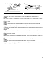
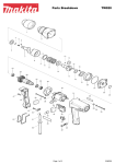
GB Angle Grinder
Instruction Manual
F
Meuleuse d’angle
Manuel d’instructions
D
Winkelschleifer
Betriebsanleitung
I
Smerigliatrice angolare
Istruzioni per l’uso
NL Haakse slijpmachine
Gebruiksaanwijzing
E
Amoladora
Manual de instrucciones
P
Rebarbadora
Manual de instruções
DK Vinkelsliber
Brugsanvisning
S
Vinkelslipmaskin
Bruksanvisning
N
Vinkelsliper
Bruksanvisning
SF Kulmahiomakone
Käyttöohje
GR Γωνιακς λειαντήρας
Οδηγίες χρήσεως
100 mm 9560C/9560CV/9563C/9563CV
115 mm 9561C/9561CV/9564C/9564CV
125 mm 9562C/9562CV/9565C/9565CV
1
2
2
3
4
1
2
5
6
3
4
7
8
10
9
11
5
6
12
2
15
7
2
8
A
B
13
14
15˚– 30˚
9
10
Symbols
The followings show the symbols used for the tool. Be sure that you understand their meaning before use.
Symboles
Nous donnons ci-dessous les symboles utilisés pour l’outil. Assurez-vous que vous en avez bien compris la signification avant d’utiliser l’outil.
Symbole
Die folgenden Symbole werden für die Maschine verwendet. Machen Sie sich vor der Benutzung unbedingt mit ihrer
Bedeutung vertraut.
Symboli
Per questo utensile vengono usati i simboli seguenti. Bisogna capire il loro significato prima di usare l’utensile.
Symbolen
Voor dit gereedschap worden de volgende symbolen gebruikt. Zorg ervoor dat u de betekenis van deze symbolen
begrijpt alvorens het gereedschap te gebruiken.
Símbolos
A continuación se muestran los símbolos utilizados con esta herramienta. Asegúrese de que entiende su significado
antes de usarla.
Símbolos
O seguinte mostra os símbolos utilizados para a ferramenta. Certifique-se de que compreende o seu significado antes
da utilização.
Symboler
Nedenstående symboler er anvendt i forbindelse med denne maskine. Vær sikker på, at De har forstået symbolernes
betydning, før maskinen anvendes.
Symboler
Det följande visar de symboler som används för den här maskinen. Se noga till att du förstår deras innebörd innan
maskinen används.
Symbolene
Følgende viser de symblene som brukes for maskinen. Det er viktig å forstå betydningen av disse før maskinen tas i
bruk.
Symbolit
Alla on esitetty koneessa käytetyt symbolit. Opettele näiden merkitys, ennen kuin käytät konetta.
Σύµβολα
Τα ακλουθα δείχνουν τα σύµβολα που χρησιµοποιούνται για το µηχάνηµα. Βεβαιωθείτε τι καταλαβαίνετε
τη σηµασία τους πριν απ τη χρήση.
3
4
❏ Read instruction manual.
❏ Lire le mode d’emploi.
❏ Bitte Betriebsanleitung lesen.
❏ Leggete il manuale di istruzioni.
❏ Lees de gebruiksaanwijzing.
❏ Lea el manual de instrucciones.
❏ Leia o manual de instruções.
❏ Læs brugsanvisningen.
❏ Läs bruksanvisningen.
❏ Les bruksanvisingen.
❏ Katso käyttöohjeita.
❏ ∆ιαβάστε τις οδηγίες χρήσης
❏ DOUBLE INSULATION
❏ DOUBLE ISOLATION
❏ DOPPELT SCHUTZISOLIERT
❏ DOPPIO ISOLAMENTO
❏ DUBBELE ISOLATIE
❏ DOBLE AISLAMIENTO
❏ DUPLO ISOLAMENTO
❏ DOBBELT ISOLATION
❏ DUBBEL ISOLERING
❏ DOBBEL ISOLERING
❏ KAKSINKERTAINEN ERISTYS
❏ ∆ΙΠΛΗ ΜΟΝΩΣΗ
❏ Wear safety glasses.
❏ Porter des lunettes de protection.
❏ Schutzbrille tragen.
❏ Indossare occhiali di protezione.
❏ Draag een veiligheidsbril.
❏ Póngase gafas de seguridad.
❏ Utilize óculos de segurança.
❏ Bær sikkerhedsbriller.
❏ Bär skyddsglasögon.
❏ Bruk vernebriller
❏ Käytä suojalaseja
❏ Φορέστε γυαλιά ασφαλείας.
ENGLISH
Explanation of general view
1
2
3
4
5
Wheel cover
Screw
Lever
Bearing box
Press
6
7
8
9
10
Shaft lock
Lock nut
Depressed center wheel
Inner flange
Lock nut wrench
11
12
13
14
15
Shaft lock
Switch lever
Exhaust vent
Inhalation vent
Speed adjusting dial
SPECIFICATIONS
100mm M10
9560C
9563C
9560CV
9563CV
115mm M14
9561C
9564C
9561CV
9564CV
125mm M14
9562C
9565C
9562CV
9565CV
No load speed (min–1)
11,000
11,000
2,800 – 11,000
2,800 – 11,000
Overall length
289 mm
299 mm
289 mm
299 mm
1.7 kg
1.8 kg
1.7 kg
1.8 kg
Depressed center wheel
diameter/Spindle thread
Net weight
• Due to our continuing program of research and development, the specifications herein are subject to change
without notice.
• Note: Specifications may differ from country to country.
9.
Power supply
The tool should be connected only to a power supply of
the same voltage as indicated on the nameplate, and can
only be operated on single-phase AC supply. They are
double-insulated in accordance with European Standard
and can, therefore, also be used from sockets without
earth wire.
10.
Safety hints
For your own safety, please refer to the enclosed safety
instructions.
ADDITIONAL SAFETY RULES
ENB031-4
1.
2.
3.
4.
5.
6.
7.
8.
Always use eye and ear protection. Other personal protective equipment such as dust mask,
gloves, helmet and apron should be worn when
necessary. If in doubt, wear the protective equipment.
Always be sure that the tool is switched off and
unplugged before carrying out any work on the
tool.
Keep guards in place.
Use only wheels with correct size and wheels
having a maximum operating speed at least as
high as the highest No Load Speed marked on
the tool’s nameplate.When using depressed center wheels, be sure to use only fiberglass-reinforced wheels.
Check the wheel carefully for cracks or damage
before operation. Replace cracked or damaged
wheel immediately.
Observe the instructions of the manufacturer for
correct mounting and use of wheels. Handle and
store wheels with care.
Do not use separate reducing bushings or adaptors to adapt large hole abrasive wheels.
Use only flanges specified for this tool.
11.
12.
13.
14.
15.
16.
17.
18.
19.
20.
21.
22.
23.
24.
25.
Do not damage the spindle, the flange (especially the installing surface) or the lock nut. Damage to these parts could result in wheel
breakage.
For tools intended to be fitted with threaded hole
wheel, ensure that the thread in the wheel is long
enough to accept the spindle length.
Before using the tool on an actual workpiece,
test run the tool at the highest no load speed for
at least 30 seconds in a safe position. Stop
immediately if there is any vibration or wobbling
that could indicate poor installation or a poorly
balanced wheel. Check the tool to determine the
cause.
Check that the workpiece is properly supported.
Hold the tool firmly.
Keep hands away from rotating parts.
Make sure the wheel is not contacting the workpiece before the switch is turned on.
Use the specified surface of the wheel to perform the grinding.
Do not use cutting off wheel for side grinding.
Watch out for flying sparks. Hold the tool so that
sparks fly away from you and other persons or
flammable materials.
Pay attention that the wheel continues to rotate
after the tool is switched off.
Do not touch the workpiece immediately after
operation; it may be extremely hot and could
burn your skin.
Position the tool so that the power cord always
stays behind the tool during operation.
If working place is extremely hot and humid, or
badly polluted by conductive dust, use a shortcircuit breaker (30mA) to assure operator safety.
Do not use the tool on any materials containing
asbestos.
Do not use water or grinding lubricant.
Ensure that ventilation openings are kept clear
when working in dusty conditions. If it should
become necessary to clear dust, first disconnect
the tool from the main supply (use non metallic
objects) and avoid damaging internal parts.
SAVE THESE INSTRUCTIONS.
5
OPERATING INSTRUCTIONS
Installing wheel guard (Fig. 1 & 2)
Important:
Always be sure that the tool is switched off and
unplugged before installing or removing the wheel guard.
Pull the lever in the direction of the arrow after loosening
the screw.
Install the wheel cover on the bearing box by adjusting
the convex of the wheel cover to the concave of the bearing box.
Turn the wheel cover by 180 degrees. Fasten it with the
screw after pulling lever in the direction of the arrow for
the working purpose, the setting angle of the wheel cover
can be adjusted with the lever.
Speed adjusting dial (For model 9560CV, 9561CV,
9562CV, 9563CV, 9564CV, 9565CV) (Fig. 8)
The rotating speed can be changed by turning the speed
adjusting dial to a given number setting from 1 to 5.
Higher speed is obtained when the dial is turned in the
direction of number 5. And lower speed is obtained when
it is turned in the direction of number 1. Refer to the table
below for the relationship between the number settings
on the dial and the approximate rotating speed.
Number
min–1(R.P.M.)
1
2,800
2
4,000
3
6,500
Removing wheel cover
4
9,000
Follow the installation procedure in reverse to remove the
wheel cover.
5
11,000
Installing side grip (auxiliary handle) (Fig. 3)
Important:
Always be sure that the tool is switched off and
unplugged before installing or removing the side grip.
Always install the side grip on the tool securely before
operation. The side grip can be installed on either side of
the tool, whichever is convenient and keeps the guard
properly positioned. Always hold the tool’s switch handle
and the side grip firmly with both hands during operation.
Shaft lock (Fig. 4)
Press the shaft lock to prevent spindle rotation when
installing or removing accessories.
CAUTION:
Never actuate the shaft lock when the spindle is moving.
The tool may be damaged.
Installing or removing depressed center wheel
(Fig. 5 & 6)
Important:
Always be sure that the tool is switched off and
unplugged before installing or removing the wheel.
Mount the inner flange onto the spindle. Fit the wheel on
over the inner flange and screw the lock nut onto the
spindle.
To tighten the lock nut, press the shaft lock firmly so that
the spindle cannot revolve, then use the lock nut wrench
and securely tighten clockwise. To remove the wheel, follow the installation procedure in reverse.
Switch action (Fig. 7)
CAUTION:
Before plugging in the tool, always check to see that the
switch actuates properly and returns to the “OFF” position when the side of the switch lever is depressed.
To start the tool, slide the switch lever to “I” position.
For continuous operation, depress the front of the switch
lever and then slide to “I” position as above. The switch is
locked on the position for continuous operation. To stop
the tool from the locked position, slide the switch lever to
“O” position with depressing the rear of the switch lever.
6
CAUTION:
• If the tool is operated continuously at low speeds for a
long time, the motor will get overloaded and heated up.
• The speed adjusting dial can be turned only as far as 5
and back to 1. Do not force it past 5 or 1, or the speed
adjusting function may no longer work.
The tools equipped with electronic function are easy to
operate because of the following features.
• Constant speed control
Electronic speed control for obtaining constant speed.
Possible to get fine finish, because the rotating speed
is kept constantly even under the loaded condition.
• Soft start feature
Safety and soft start because of suppressed starting
shock.
• Overload protector
When the tool would be employed over the admissible
load, it will stop automatically to protect the motor and
wheel. When the load will come to the admissible level
again, the tool can be started automatically.
Operation (Fig. 9)
CAUTION:
After operation, always switch off the tool and wait until
the wheel has come to a complete stop before putting the
tool down.
Hold the tool firmly with both hands. Turn the tool on and
then apply the wheel or disc to the workpiece.
In general, keep the edge of the wheel or disc at an angle
of about 15° – 30° to the workpiece surface. During the
break-in period with a new wheel, do not work the tool in
the B direction or it will cut into the workpiece. Once the
edge of the wheel has been rounded off by use, the
wheel may be worked in both A and B directions.
WARNING:
• It should never be necessary to force the tool. The
weight of the tool applies adequate pressure. Forcing
and excessive pressure could cause dangerous wheel
breakage.
• Continued use of a worn-out wheel may result in wheel
explosion and serious personal injury.
MAINTENANCE
CAUTION:
Always be sure that the tool is switched off and
unplugged before carrying out any work on the tool.
Repair and maintenance (Fig. 10)
The tool and its opening vents for cooling air have to be
always kept clean. When the foreign matters clog such
parts, they have to be taken off.
To maintain product safety and reliability, repairs, maintenance or adjustment should be carried out by a Makita
Authorized Service Center.
ACCESSORIES
CAUTION:
• These accessories or attachments are recommended
for use with your Makita tool specified in this manual.
The use of any other accessories or attachments might
present a risk of injury to persons. Only use accessory
or attachment for its stated purpose.
If you need any assistance for more details regarding
these accessories, ask your local Makita service center.
•
•
•
•
•
•
Wheel guard
Depressed center grinding wheel
Abrasive disc
Wire cup brush
Rubber pad
Sanding lock nut
7
NEDERLANDS
Verklaring van algemene gegevens
1
2
3
4
5
Beschermkap
Schroef
Hendel
Kussenblokkast
Drukken
6
7
8
9
10
Asvergrendeling
Sluitmoer
Schijf met verzonken asgat
Binnenflens
Borgmoersleutel
11
12
13
14
15
Asvergrendeling
Schakelaar
Luchtuitlaatopening
Luchtinlaatopening
Toerentalregelknop
TECHNISCHE GEGEVENS
Diameter slijpschijf /
Asschroefdraad
100mm M10
9560C
9563C
9560CV
9563CV
115mm M14
9561C
9564C
9561CV
9564CV
9562C
9565C
9562CV
9565CV
Toerental onbelast/min. (min–1)
125mm M14
11 000
11 000
2 800 – 11 000
2 800 – 11 000
Totale lengte
289 mm
299 mm
289 mm
299 mm
Netto gewicht
1,7 kg
1,8 kg
1,7 kg
1,8 kg
• In verband met ononderbroken research en ontwikkeling behouden wij ons het recht voor bovenstaande
technische gegevens te wijzigen zonder voorafgaande
kennisgeving.
• Opmerking: De technische gegevens kunnen van land
tot land verschillen.
Stroomvoorziening
De machine mag alleen worden aangesloten op een
stroombron van hetzelfde voltage als aangegeven op de
naamplaat, en kan alleen op enkel-fase wisselstroom
worden gebruikt. De machine is dubbel-geïsoleerd volgens de Europese standaard en kan derhalve ook op
een niet-geaard stopcontact worden aangesloten.
Veiligheidswenken
Voor uw veiligheid dient u de bijgevoegde veiligheidsvoorschriften nauwkeurig op te volgen.
AANVULLENDE
VEILIGHEIDSVOORSCHRIFTEN VOOR HET
GEREEDSCHAP
1.
2.
3.
4.
5.
Draag tijdens het gebruik van het gereedschap
altijd oog- en oorbeschermers. Draag indien
nodig ook andere persoonlijke veiligheidsuitrusting zoals een stofmasker, handschoenen, een
helm en een voorschoot. Draag voor alle zekerheid de veiligheidsuitrusting in geval van twijfel.
Schakel het gereedschap uit en haal zijn netsnoer uit het stopcontact alvorens enig werk aan
het gereedschap uit te voeren.
Houd de beschermkappen op hun plaats.
Gebruik uitsluitend schijven van de juiste
grootte en met een maximaal bedrijfstoerental
dat minstens even hoog is als het hoogste “No
Load Speed” (toerental onbelast) dat op de
naamplaat van het gereedschap is opgegeven.
Wanneer u schijven met een verzonken asgat
gebruikt, gebruik dan uitsluitend schijven die
met glasvezel zijn versterkt.
Controleer de schijf vóór elk gebruik zorgvuldig
op scheuren, barsten of beschadiging. Vervang
een gescheurd, gebarsten of beschadigd schijf
onmiddellijk.
6.
7.
8.
9.
10.
11.
12.
13.
14.
15.
16.
17.
18.
19.
Volg de instructies van de fabrikant voor het juist
monteren en gebruiken van de schijven zorgvuldig op. Behandel de schijven voorzichtig en berg
deze met zorg op.
Gebruik geen afzonderlijke verloopmoffen of
adapters om schuurschijven met een groot asgat
aan dit gereedschap aan te passen.
Gebruik uitsluitend flenzen die voor dit gereedschap zijn bestemd.
Pas op dat u de as, de flens (vooral het montagevlak) of de klembout niet beschadigt. Beschadiging van deze onderdelen kan leiden tot
schijfbreuk.
Voor gereedschap waarop schijven met een
geschroefd asgat dienen gemonteerd te worden,
moet u ervoor zorgen dat de schroefdraad in de
schijf lang genoeg zodat de as helemaal erin
gaat.
Laat het gereedschap tenminste 30 seconden
lang met het maximale onbelaste toerental
draaien op een veilige plaats alvorens het op een
werkstuk te gebruiken. Stop het gereedschap
onmiddellijk als er sprake is van trilling of
beving die het gevolg kunnen zijn van onjuiste
installatie of een slecht uitgebalanceerde schijf.
Controleer het gereedschap om de oorzaak van
het probleem te bepalen.
Zorg ervoor dat het werkstuk goed ondersteund
is.
Houd het gereedschap stevig vast.
Houd uw handen uit de buurt van draaiende
onderdelen.
Zorg ervoor dat schuurschijf het werkstuk niet
raakt voordat het gereedschap is ingeschakeld.
Voor slijpwerkzaamheden moet u het schijfoppervlak gebruiken dat daarvoor bestemd is.
Gebruik de doorslijpschijf niet voor zijdelings
slijpen.
Pas op voor rondvliegende vonken. Houd het
gereedschap zodanig vast dat er geen vonken
op uzelf, andere personen of ontvlambaar materiaal terecht kunnen komen.
Houd er rekening mee dat de schijf nog een tijdje
blijft draaien nadat het gereedschap is uitgeschakeld.
17
20. Raak het werkstuk niet aan onmiddellijk na het
werk; het werkstuk kan gloeiend heet zijn en
brandwonden veroorzaken.
21. Plaats het gereedschap zodanig dat zijn netsnoer tijdens het gebruik altijd achter het gereedschap blijft.
22. Indien de werkplaats uiterst warm en vochtig is,
of erg verontreinigd is door geleidend stof,
gebruik dan een stroomonderbreker (30 mA) om
de veiligheid van de gebruiker te verzekeren.
23. Gebruik het gereedschap niet op materialen die
asbest bevatten.
24. Gebruik geen water of slijpolie.
25. Zorg dat de ventilatieopeningen niet geblokkeerd zijn wanneer u in stoffige omgevingen
werkt. Indien stof verwijderd moet worden, trek
dan eerst de stekker uit het stopcontact (gebruik
niet-metalen voorwerpen) en let op dat u geen
interne onderdelen van het gereedschap beschadigt.
Asvergrendeling (Fig. 4)
Wanneer u accessoires installeert of verwijdert, moet u
de asvergrendeling indrukken om te voorkomen dat de
as kan draaien.
LET OP:
Druk de asvergrendeling nooit in terwijl de as nog draait.
Hierdoor kan de machine beschadigd raken.
Installeren en verwijderen van de
afbraamschijf (Fig. 5 en 6)
Belangrijk:
Zorg er altijd voor dat het apparaat uitgeschakeld is en
de aansluiting op de voedingsbron verbroken is, alvorens
de afbraamschijf te installeren of te verwijderen.
BEDIENINGSVOORSCHRIFTEN
Monteer de binnenflens op de as. Plaats de schijf over de
binnenflens en bevestig het geheel stevig door de sluitmoer op de as vast te draaien.
Voor het vastzetten van de sluitmoer, dient u stevig op de
asvergrendeling te drukken zodat de as niet rond kan
draaien en vervolgens met een nokkensleutel de sluitmoer stevig naar rechts vast te draaien.
Om de schijf te verwijderen dient u in omgekeerde volgorde van installatie te werk te gaan.
Monteren van de beschermkap (Fig. 1 en 2)
Werking van de schakelaar (Fig. 7)
Belangrijk:
Zorg er altijd voor dat de machine is uitgeschakeld en de
aansluiting op het stopcontact is verbroken, alvorens de
beschermkap te installeren of te verwijderen.
LET OP:
Alvorens het gereedschap op een stopcontact aan te
sluiten, moet u altijd controleren of de schakelaar
behoorlijk werkt en naar de “OFF” positie terugkeert
wanneer u de zijkant van de schakelaar neerdrukt.
BEWAAR DEZE VOORSCHRIFTEN.
Maak de schroef los en trek de hendel in de richting van
het pijltje.
Monteer de beschermkap op de kussenblokkast zodanig
dat het bolle gedeelte van de beschermkap past in het
holle gedeelte van de kussenblokkast. Draai de
beschermkap 180 graden rechtsom. Trek de hendel in de
richting van het pijltje en zet dan de beschermkap vast
door middel van de schroef. U kunt de hoek van de
beschermkap met de hendel in de gewenste positie zetten om gemakkelijker te kunnen werken.
Verwijderen van de beschermkap
Om de beschermkap te verwijderen, volgt u de procedure voor het monteren in omgekeerde volgorde.
Monteren van de zijhandgreep
(hulphandgreep) (Fig. 3)
Belangrijk:
Zorg er altijd voor dat de machine is uitgeschakeld en de
aansluiting op het stopcontact is verbroken, alvorens de
zijhandgreep te installeren of te verwijderen.
Monteer de zijhandgreep altijd vast op het gereedschap
voordat u met het slijpen begint. De zijhandgreep kan
aan beide kanten van het gereedschap worden bevestigd; kies de positie die voor u het gemakkelijkst is en die
de beschermkap op de juiste plaats houdt. Houd tijdens
het slijpen de schakelaarhandgreep en de zijhandgreep
altijd stevig vast met beide handen.
18
Schuif de schakelaar naar de “I” positie om het gereedschap te starten.
Voor doorlopend slijpen, drukt u het voorste gedeelte van
de schakelaar neer en dan schuift u de schakelaar naar
de “I” positie zoals hierboven. De schakelaar blijft dan in
deze positie vastgezet voor continuë werking. Om het
gereedschap vanuit de vergrendelde stand te stoppen,
schuift u de schakelhendel naar de “O” positie terwijl u
het achterste gedeelte ervan indrukt.
Toerentalregelknop (Voor modellen 9560CV,
9561CV, 9562CV, 9563CV, 9564CV, 9565CV)
(Fig. 8)
U kunt de draaisnelheid veranderen door de toerentalregelknop te draaien en in te stellen op een cijfer van 1 tot
5.
De snelheid verhoogt wanneer u de draaiknop in de richting van het cijfer 5 draait. De snelheid verlaagt wanneer
u deze in de richting van het cijfer 1 draait. Zie de onderstaande tabel voor de verhouding tussen de cijfers op de
draaiknop en de approximatieve draaisnelheid.
Cijfer
min–1 (RPM)
1
2 800
2
4 000
3
6 500
4
9 000
5
11 000
LET OP:
• Wanneer u het gereedschap lange tijd achtereen bij
een lage snelheid gebruikt, kan de motor overbelast en
oververhit worden.
• De toerentalregelknop kan niet verder dan 5 en niet
verder terug dan 1 worden gedraaid. Forceer de draaiknop niet voorbij 5 of 1, aangezien de toerentalregeling
dan niet meer juist zal werken.
Gereedschappen die voorzien zijn van een elektronische
functie zijn gemakkelijk te bedienen dank zij de volgende
kenmerken.
• Handhaving van een constant toerental
Gereedschappen die voorzien zijn van een elektronische functie zijn gemakkelijk te bedienen dank zij de
volgende kenmerken.
• Elektronische toerentalregeling verzekert een constant
toerental.
U kunt fijn afwerken, aangezien de draaisnelheid tijdens belast draaien constant gelijk wordt gehouden.
Zachte start De aanloopschok wordt onderdrukt zodat
u veilig kunt werken en zacht kunt starten.
• Beveiliging tegen overbelasting
Wanneer de toelaatbare belasting van het gereedschap wordt overschreden, stopt het gereedschap
automatisch om de motor en de schijf te beschermen.
Zodra de belasting tot het toelaatbare niveau is
gedaald, kan het gereedschap weer automatisch worden gestart.
Bediening (Fig. 9)
LET OP:
Schakel na het gebruik de machine altijd uit en wacht totdat de schijf volledig tot stilstand is gekomen, alvorens de
machine neer te zetten.
ONDERHOUD
LET OP:
Zorg er altijd voor dat de machine is uitgeschakeld en de
stekker uit het stopcontact is verwijderd alvorens onderhoud aan de machine uit te voeren.
Reparatie en onderhoud (Fig. 10)
Houd het gereedschap en zijn luchtkoelopeningen altijd
schoon. Zorg ervoor dat deze openingen niet door verontreinigingen verstopt raken.
Opdat de machine veilig en betrouwbaar blijft, dienen alle
reparaties, onderhoud of afstellingen te worden uitgevoerd bij een erkend Makita service centrum.
ACCESSOIRES
LET OP:
• Deze accessoires of hulpstukken worden aanbevolen
voor gebruik met het Makita gereedschap dat in deze
gebruiksaanwijzing is beschreven. Bij gebruik van
andere accessoires of hulpstukken bestaat er gevaar
voor persoonlijke verwonding. Gebruik de accessoires
of hulpstukken uitsluitend voor hun bestemd doel.
Wenst u meer bijzonderheden over deze accessoires,
neem dan contact op met het plaatselijke Makita servicecentrum.
•
•
•
•
•
•
Beschermkap
Schijf met verzonken asgat
Schuurschijf
Komvormige draadborstel
Rubberkussen
Borgmoer
Houd het gereedschap met beide handen stevig vast.
Schakel het apparaat in en breng vervolgens de schijf op
het werkstuk. In het algemeen dient u de rand van de
schijf in een hoek van 15° – 30° ten opzichte van het
werkstukoppervlakte houden.
Bij gebruik van een nieuwe schijf dient u deze niet in de
richting van B te gebruiken, aangezien deze hierdoor in
het werkstuk kan snijden. Wanneer de rand van de schijf
door gebruik ronder geworden is, kunt u de schijf zowel in
de A als de B richting gebruiken.
WAARSCHUWING:
• U dient nooit kracht op het apparaat uit te oefenen. Het
eigen gewicht van de machine levert voldoende druk
op. Krachtzetten en overmatig druk kan resulteren in
het breken van de schijf, hetgeen gevaarlijk is.
• Continu gebruik van een versleten schijf kan er oorzaak van zijn dat de schijf explodeert met ernstig persoonlijk letsel als gevolg.
19