1
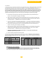
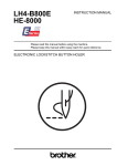
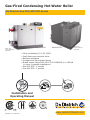
Gas-Fired Condensing Hot Water Boiler
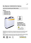
De Dietrich Gas 310/610 ECO Series
Gas 310 ECO
Boiler may
not be exactly as
illustrated.
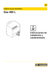
Gas 610 ECO
Boiler may
not be exactly as
illustrated.
•
•
•
•
•
Fully modulating (5:1) 20-100%
Cast Aluminum sectional boiler
Reduced emissions
Compact and light weight design
Broad output range from 63 to 3,911 MBH/18 to 1,146 kW
or more in cascade installations
• Gas 310 ECO - 5 models
• Gas 610 ECO - 4 models
Installation and
Operating Manual
G310E 01 v1.0 04/2010
www.dedietrichboilers.com
De Dietrich Gas 310/610 ECO
Warning:
Before you operate this boiler, read this manual carefully and take extra precautions to all safety and warning symbols or important
items. The operating manual is part of the documentation along with the boiler. The installer is required to explain your heating
system and boiler operating instructions.
Notice:
Please read t his manual and retain f or future reference. Improper installation, adj ustment, al teration, s ervice or maintenance c an
cause i njury, l oss of l ife or pr operty da mage. R efer to this manual f or a ssistance or addi tional i nformation or c onsult a qual ified
installer, service agency or the gas supplier.
important:
This is a category II or IV boiler, only use an
approved type ‘BH’ vent material or equivalent,
consult the venting section in this manual
In the interest of customers, DE DIETRICH & DDR Americas are continuously endeavoring to make improvements in
product quality.
All the specifications stated in this document are therefore subject to change without notice
1
De Dietrich Gas 310/610 ECO
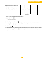
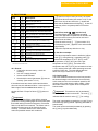
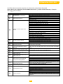
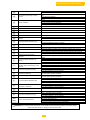
TABLE OF CONTENTS
PREFACE
5
1. SAFETY INSTRUCTIONS
1.1
Symbols
General Instructions
Modifications – Spare parts
6
6
6
6
2. DESCRIPTION OF BOILER
7
3. DESIGN
Boiler version
Operating principle
8
8
9
Dimensions
Technical data
Quotation specifications
Delivery options
Gas 610 Quotation Specification
Delivery and ordering options
10
10
11
16
16
17
17
3.1
3.2
4. TECHNICAL DATA
4.1
4.2
4.3
4.4
4.5
4.6
5. EFFICIENCY INFORMATION
5.1
Combustion efficiency
5.2
Thermal efficiency
5.3
Standby losses
18
18
18
18
6. APPLICATION DATA
18
7. INSTALLATION INSTRUCTIONS
7.1
General
7.2
Delivery and installation
7.3
Flue gas discharge and air supply
7.3.1
General
7.3.2
Boiler venting types
7.3.3
Venting options
7.3.4
Vent terminations
7.3.5
Combustion air supply requirements
7.3.6
Chimney & CLV systems
7.3.7
Direct vent or DVS systems
7.3.8
Co-venting precautions
7.3.9
Vent terminations precautions
18
18
18
21
21
21
21
21
21
22
23
24
25
7.4 INSTALLATION DETAILS
7.4.1
Water pressure
7.4.2
Condensate discharge
7.4.3
Water treatment
7.4.4
Safety relief valve
7.4.5
Water flow & content
7.4.6
Noise pollution
7.5
Multiple boiler installation
7.6
Typical water system layout
26
26
26
26
26
26
26
26
27
8. INSTALLATION INSTRUCTIONS FOR ELECTRICAL INSTALLER
8.1
General
8.2
Electrical specifications
8.2.1
Main power voltage
8.2.2
Control unit
8.2.3
Power consumption
8.2.4
Fuse ratings
8.2.5
Temperature control
8.2.6
Low water level protection
8.2.7
Hi-Limit protection
8.2.8
Air pressure differential sensor
28
28
28
28
28
28
29
29
29
29
29
2
De Dietrich Gas 310/610 ECO
8.3
8.4
8.5
8.6
8.6.1
Connections
Wiring diagram
Sequence of operation
Boiler control
Gas 310 Introduction
30
31
34
34
34
8.6.2
Gas 310 Modulating controls general
A. Single boiler
B. Multiple boiler
BMS Analog control
On/Off control
High/Low control
2-Stage control
4-Stage High/low control
Other inputs
Shutdown input
Lockout input
External interlock
Other Outputs
Analog output
Operational signal
Common alarm
External gas valve
Optional inputs
System pressure sensor
Gas valve leak proving system
Low gas pressure switch
Flue gas damper
Return butterfly valve
Other connections
Boiler or system pump control
Frost protection
35
35
35
35
36
36
37
37
37
37
37
37
38
38
38
39
39
39
39
39
39
40
40
40
40
40
8.6.3
8.6.4
8.6.5
8.6.6
8.6.7
8.7
8.7.1
8.7.2
8.7.3
8.7.4
8.7.5
8.7.6
8.7.7
8.7.8
8.8
8.8.1
8.8.2
8.8.3
8.8.4
8.8.5
8.9
8.9.1
8.9.2
9. GAS INSTALLATION INSTRUCTIONS
9.1
Gas connection
9.2
Gas pressure
9.3
Gas/air ratio control
41
41
41
41
10. COMMISSIONING
10.1
10.2
42
42
45
Initial lighting
Shutdown
11. CONTROL AND SAFETY EQUIPMENT
11.1
General
11.1.1
Instrument panel layout
11.1.2
LED indicators
11.2
Switch function key
11.2.1
Manual/Automatic operation
11.2.2
Forced High mode
11.2.3
Forced Low mode
11.3
Display of values
46
46
46
47
47
47
47
47
48
12. OPEARATING MODE
12.1
12.2
12.3
12.4
12.4.1
12.4.2
12.5
12.5.1
12.5.2
Operating mode
Read out mode
Control strategy
Shut-off
Shut-off
Shut-off mode
Counter mode
General
Reading out counter mode
48
48
49
50
50
50
50
51
51
51
13. SETTING MODE
13.1
13.1.1
13.1.2
13.1.3
13.2
User level setting mode
Flow temperature
Pump run on time
Boiler control
Setting mode service level
52
52
52
53
53
53
3
De Dietrich Gas 310/610 ECO
13.2.1
13.2.2
13.2.3
13.2.4
13.2.5
13.2.6
13.2.7
13.2.8
13.2.9
13.2.10
13.2.11
13.2.12
13.2.13
13.2.14
13.2.15
14. FAULT-FINDING
14.1
14.2
14.3
14.4
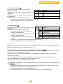
Table 16 – Service level setting mode
Minimum fan speed
Maximum fan speed
Forced part load time
Cycling prevention delay time
Required flow temperature
Switch point high/low operation
Shunt pump post-purge time
T from control stops point to start point ()
Maximum flue gas temperature
High limit temperature setting
Modulation start point at ∆T
Minimum water pressure
Adjustments option/accessory
Low speed with H/L control
Boiler type
54
55
55
55
55
55
55
55
56
56
56
56
56
56
57
57
58
58
58
58
59
60
General
Failure mode
Cooling mode
Summary of failure (lock-out)
Table 23 Failure codes
15. INSPECTION AND MAINTENANCE
15.1
General
15.2
Cooling mode
15.3
Annual inspection
15.4
Maintenance
15.4.1
Inspection of air box and dirt trap
15.4.2
Non return valve cleaning
15.4.3
Venturi cleaning
15.4.4
Fan cleaning
15.4.5
Heat exchanger cleaning
15.4.6
Burner assembly cleaning
15.4.7
Condensate collector cleaning
15.4.8
Condensate siphon cleaning
15.4.9
Ignition/ionization electrode cleaning
15.4.10 Gas filter check
15.4.11 Inspection glass cleaning
15.5
Explode part view
15.5.1
Spare parts listing
61
61
61
61
62
62
62
62
63
63
63
64
64
64
65
65
66
67
16. APPENDICES
69
70
71
16.1
16.2
Control menu
shut-off codes
73
73
74
74
17. COMMISSIONING & MAINTANENCE
17.1
Boiler commissioning report
17.2
Boiler control settings
17.3
Routine maintenance checklist
4
De Dietrich Gas 310/610 ECO
PREFACE
Read t hese i nstructions c arefully, bef ore pu tting t he boi ler i nto op eration, f amiliarize your-self w ith i ts
control f unctions, op eration and s trictly observe t he instructions g iven. F ailure t o do s o m ay invalidate
warranty or prevent the boiler from operating.
The Installation and commissioning of the boiler needs to be performed by a licensed and trained heating
contractor. A c omplete commissioning report must be performed, r ecorded an d s ent t o DDR Americas
Inc. for successfully active t he pr oduct warranty, t he s tartup r eport a nd an y service records w ill b e
requested when any warranty claims are made.
If you have any questions or require more information about specific subjects relating to this boiler or its
installation please do not hesitate to contact us.
The data published in these technical instructions is based on the latest information (at date of
publication) and may be subject to revisions.
We r eserve al l t he r ight t o c ontinuous d evelopment i n both d esign a nd m anufacture, t herefore an y
changes t o t he t echnology e mployed m ay n ot be r etrospective nor m ay we be obliged t o adj ust ear lier
supplies accordingly.
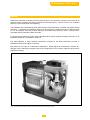
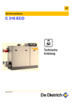
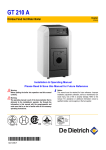
Fig 01 – Gas 310 ECO 3D. Gas 610 ECO consists of one Gas 310-L (left hand) and one Gas 310-R (right hand).
5
De Dietrich Gas 310/610 ECO
1
SAFETY INSTRUCTIONS
1.1 Symbols
The f ollowing symbols are us ed in t his d ocument to emphasize certain instructions. This is i n order t o
increase your personal safety and to safeguard the technical reliability of the boiler.
Instructions must be followed closely to avoid personal injury or serious damage to the unit or the
environment.
Important!!
Instructions are of essential importance for the correct functioning of the unit.
= Indicates danger of electrical shock. Serious personal injury may occur.
Read
and familiarize yourself with these instructions:
Instructions contain useful information
General Instructions
Keep unauthorized personnel away from the boiler. Do not place objects on or against the boiler. Do not
touch hot water connections or the flue outlet when the boiler is operating – burn hazard.
Danger
This boiler is connected to a 120v power supply. An improper installation or attempts to repair electrical
components or controls may result in life threatening situations.
WHAT TO DO IF YOU SMELL GAS:
• Do not smoke and make no fire or sparks;
• Do not operate electrical switches
• Do not use any phone in the building
• Immediately call your gas supplier from another building. If the gas suppler is not available, call
9-1-1
Warning!
Follow the gas supplier’s instructions.
Be aware of flue gas leaks
If you smell flue gas fumes, turn the boiler off and contact your service company or installer.
Beware of water leaks
If you see water leaking from the boiler, turn it off and contact your service company or installer.
Working on the boiler
Installation, commissioning, maintenance and repair work must only be carried out by a licensed and
qualified technician. Designed and engineered in accordance with all relevant national/local standards
and certifications.
Always disconnect the main power supply and close the main gas cock before working on the boiler.
Casing panels should only be removed for maintenance and servicing purposes. Refit all panels on
completion of maintenance or servicing before putting the boiler back into service.
Instructions and warning labels on the boiler must never be removed or covered and must be clearly
legible throughout the entire service life of the boiler. Damaged or illegible instructions and warning labels
must be replaced immediately.
Generally applicable safety instructions related to accident prevention must be consulted in addition to the
information supplied in this technical documentation.
Boiler modification and spare parts
6
De Dietrich Gas 310/610 ECO
The boiler must not be modified or fitted with non OEM spare parts without the express written approval
of DDR Americas Inc. [De Dietrich Boilers].
2
GENERAL DESCRIPTION OF BOILER
The Gas 310/610 ECO boiler is a fully assembled, free standing, gas fired (natural gas only), fully
modulating, high efficiency condensing boiler and is supplied, plastic wrapped, crated on a pallet.
The sectional cast aluminum heat exchanger and other major components are contained within a rigid
steel frame with removable casing parts for maintenance purposes. The Gas 310/610 ECO frame is fitted
with a set of casters to enable the assembled unit to be easily maneuvered into position within the plant
room on site with minimum effort. All major electrical and electronic controls are contained within the
instrument panel mounted on top of the boiler at the opposite end to the connections facing to the front
(long side).
The boiler is available with flow and return connections on the right hand end of the boiler, with the gas
connection on the top of the boiler. The flue gas outlet c/w a condensate connection will be at low level
on the same side as the connections. Combustion air inlet (from room sealed operation) is located at the
top of the boiler. The front or “service side” of the boiler provides access to the heat exchanger
inspection hatch and other service items, see fig. 02 and fig. 04.
The boiler is suitable for room-sealed or open flue applications and has been designed for central heating
and indirect hot water production at working pressures not exceeding 100 psig [6.8 bar]. It must be
installed on a fully pumped system and is designed for operating pressures between 11 – 100 psig [0.8 –
6.8 bar].The boiler is to be used for indoor installations only.
The pre-mix gas burner (NG only) with its gas/air ratio control system ensures clean, trouble free
operation with higher than average efficiencies of up to 99.9% in the condensing mode combined with
ultra low NOx and minimum CO emissions.
The standard control package allows for external On/Off, High Low (volt free switch/s) or modulating
control (0-10V input). The built in digital display shows normal operating/fault code indication and allows
actual and set values to be read and adjusted.
(R)
The intelligent, advanced boiler control (‘abc ’) continuously monitors the boiler operating conditions,
varying the heat output to suit the system load. The control is able to react to external “negative”
influences in the rest of the system (flow rates, air/gas supply problems) maintaining boiler output for as
long as possible without resorting to a lock out condition. At worst the boiler will reduce its output and/or
shut down (shut off mode) awaiting the “negative” conditions to return to normal before re-starting.
The ‘abc®’ control cannot override the standard flame safety controls.
All Gas 310/610 boilers are fully test fired after assembly to ensure the boiler and controls comply with
our strict quality policy.
The packaged boiler is constructed and approved according to the following standards:
▪
▪
▪
▪
▪
▪
▪
▪
ANSI Z21.13 / CSA 4.9
UL 795
CGA CAN1-3.1
ASME Section IV
CRN for each Canadian Province
Electrical according CSA 22.2 & NEC/NFPA 70
Gas Vent Category II & IV – Use vent type BH
Consult factory for other certifications or qualifications.
7
De Dietrich Gas 310/610 ECO
3 DESIGN
3.1 Boiler Version
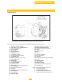
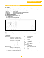
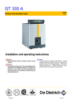
Fig. 02 Cross-section Gas 310 ECO (Left hand boiler illustrated). Gas 610 boiler consists of Gas 310-L and Gas 310-R.
The service side of the boiler (with the heat exchanger inspection cover) is the front.
1. T/P gauge (supply manifold)
2. Relief valve 1 ½ In. & additional ½ In.
port for external Hi limit
3. Flow-connection
4. Not available
5. Return-connection
6. Filling/drain cock
7. Condensate collector
8. Flue gas temperature sensor
9. Condensate drain
10. Measuring point (O2, CO2, CO)
11. Positioning wheels
12. Jacking bolts
13. Condensate drain hose
14. Flue gas discharge
15. Inspection hatch
16. Not available, 10” vent ø system only
17. Heat exchanger
18. Flow temperature sensor
19. Air supply
20. Not available, 10” vent ø system only
21. Air supply grille
22. Gas connection
23. Inspection glass
24.
25.
26.
27.
28.
29.
30.
31.
32.
33.
34.
35.
36.
37.
38.
39.
40.
Ignition/Ionization electrode
Return temperature sensor
Boiler block temperature sensor
Frame
Steering castor
Fan
Venturi
Gas valve multiblock
Non return valve
Gas filter
Air pressure differential sensor (LDS)
Air box
Instrument panel
Control Keys
Read-out window
Weather compensator (optional)
On/Off switch
Other items see parts view section 15.5:
a. Firing valve (3026)
b. Vent safety switch (3046)
c. Inlet gas adapter 2” NPT (3045)
d. Safety relief valve, see chapter 7.4.4.
8
De Dietrich Gas 310/610 ECO
e. Flue gas damper (optional for Gas 310
boiler, standard for Gas 610 boiler)
3.2 OPERATING PRINCIPLE
Combustion air is drawn into the inlet connection from the plant room (room ventilated version) or from outside via
the eccentric flue system (room sealed) by an air supply fan.
On the inlet side of the fan is a specially designed chamber (venturi unit) which takes gas from the multi-block and
mixes it in the correct proportions with the incoming air. This mixing system ensures that the correct gas/air ratio
is delivered to the pre-mix burner at all times.
Depending on demand (under the dictates of flow/return sensor and other external/internal control inputs) the
’
‘abc®’ system determines the required boiler output. The ‘abc® control then varies the speed of the air supply
fan which alters the volume of air being drawn into the venturi, this change in volume is measured using air
pressure differential which directly controls the volume of gas also being delivered to the venturi. The resultant
controlled mixture is delivered to the premix burner.
This mixture is initially ignited by the combined ignition/ionization probe which monitors the state of the flame.
Should the flame be unstable or not ignite within the pre-set safety time cycle the controls will (after 5 attempts)
shut the boiler down requiring manual intervention to reset the boiler. The digital display will indicate a flashing
fault code confirming the reason for the failure.
The products of combustion in the form of hot flue gases are forced through the heat exchanger transferring their
heat to the system water, (the flue gas temperature is reduced to approximately 9-14° F [5-8° C] above the
temperature of the system return water) then discharged via the condensate collector, to the flue gas outlet
connection, to atmosphere.
Because of the low flue gas exit temperature there will be a vapor cloud formed at the flue gas terminal – this is
not smoke -, simply water vapor formed during the combustion process.
If the flue gas temperature falls below dew point 131°F [55°C], water vapor (created during the combustion
process) will begin to condense out in the boiler, transferring its latent heat into the system water, thereby
increasing the output of the boiler with-out increasing the gas consumption.
Condensation formed within the boiler and flue system is discharged from the boiler to an external drain via the
drain pan and siphon supplied.
9
De Dietrich Gas 310/610 ECO
4 TECHINCAL DATA
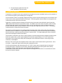
4.1 Dimensions
fig. 03 Elevation drawings
Flow connection
Return connection
Gas connection
Condensate drain
Flue gas discharge
Combustion air supply
3 inch ANSI 150# flange
2.5 inch
2 inch NPT (BSP to NPT adapter provided)
1 ¼ inch
10 inch (starter piece may be required, consult vent manufacturer)
10 inch (starter piece may be required, consult vent manufacturer)
Dimensions
310-5
310-6
310-7
310-8
310-9
mm
1590
1590
1980
1980
1980
inch
62 39/64
62 39/64
45 61/64
45 61 64
45 61/64
B
mm
1312
1312
1702
1702
1702
inch
51 21/32
51 21/32
67
67
67
D
mm
1600
1600
1990
1990
1990
inch
63
63
78 11/32
78 11/32
78 11/32
N
mm
1463
1463
1853
1853
1853
inch
57 39/64
57 39/64
72 61/64
72 61/64
72 61/64
0
mm
1004
901
1110
1007
904
inch
39 17/32
35 31/64
43 45/64
39 21/32
35 19/32
Unit
Inch
mm
C
23 15/32
596
E
23 5/8
600
F
14 3/16
360
G
12 41/64
321
H
55 13/64
1402
I
40 1/4
1022
J
14 3/8
365
K
12 39/64
320
L
17 59/64
455
M
55 33/64
1410
Unit
Inch
mm
P
26 25/32
680
Q
7 7/8
200
R
50 51/64
1290
S
28 23/64
720
T
57 3/8
1457
U
6 45/64
170
V
21/64
8
Gas 310 ECO Model
A
table 01, main dimensions, all fractions rounded up
10
De Dietrich Gas 310/610 ECO
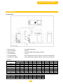
4.2 GAS 610 ECO TECHNICAL DATA
Back view
C
B
A
F
=Q=
=P=
=R=
Top (plan) view
=D=
E
I
J
K
Service side view
H
G
Heat exchanger
cleanout hatch
N
O
11
M
L
Front view
De Dietrich Gas 310/610 ECO
Gas610-6
Gas610-7
Gas610-8
Gas610-9
Model
Gas610-6
Gas610-7
Gas610-8
Gas610-9
Model
Gas610-6
Gas610-7
Gas610-8
Gas610-9
In.
mm
40.5
1029
27
In.
mm
22.2
564
A
685
14.4
In.
mm
6.7
170
G
365
10.2
In.
57.6
mm
1463
72.95
1853
In.
35.5
43.7
39.6
35.6
H
M
I
N
In.
mm
57.4
1457
E
In.
mm
In.
mm
258
57.1
1450
50.8
1290
mm
901
1110
1007
904
In.
mm
In.
mm
26.8
680
55.2
1402
J
O
K
P
In.
51.7
mm
1312
In.
63
mm
1600
67
1702
78.3
1990
F
L
Q
R
In.
mm
In.
mm
In.
mm
9.8
250
28.7
730
28.9
734
C
Model
Gas 610 ECO Series
MAIN DIMENSIONS
B
C
D
In.
mm
In.
mm
In.
mm
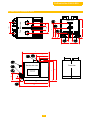
Gas 610 ECO Series
Service & Combustible Clearances (MIN)
A*
B
C
In. mm In. mm
In.
mm
12
300
12
300
31.5
800
A
C
B
12
C
De Dietrich Gas 310/610 ECO
A
A
C
D
Gas 610 ECO Series
Service & Combustible Clearances (MIN)
A*
B
C
D
In. mm In. mm
In.
mm In. mm
12 300 12 300
31.5
800 24 600
Gas 610 ECO Series
Base & leveling legs dimensions
Model
Gas610-6
Gas610-7
Gas610-8
Gas610-9
A
In.
57.08
B
mm
In.
1450 24.8
C
D
mm
In.
mm
630
4.1
104
In.
mm
1590 62.6
1980
13
F2 (Square)
E
78
In.
44
mm
1118
59.4 1508
In.
mm
2.16
55
De Dietrich Gas 310/610 ECO
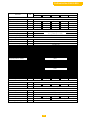
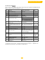
Boiler Model
Unit
De Dietrich Gas 310 ECO
310-5
310-6
310-7
310-8
310-9
General
On-Off, 2 Stage or Fully Modulating
Firing Sequence Operation
Minimum Fuel Input
MBH [kW]
205 [60]
256 [75]
311 [91]
358 [105]
413 [121]
Maximum Fuel Input
MBH [kW]
1,017 [298]
1,269 [372]
1,529 [448]
1,785 [523]
2,041 [598]
Minimum Heat Output
MBH [kW]
191 [56]
242 [71]
287 [84]
334 [98]
386 [113]
Maximum Heat Output
MBH [kW]
962 [282]
1,205 [353]
1,457 [427]
1,703 [499]
1,955 [573]
Efficiency
Combustion [Gross]
%
CSA Certified
Certified Avg.
Avg. 97.4
95.3 –
- [potential
CSA
(potentialup
uptoto≈≅99.0]
99.9%)
Thermal Efficiency [Net]
%
97.2–- (potential
[potential up to ≈
95.3
≅ 98.5]
99.9%)
Standby Losses [Average]
%
< 0.3
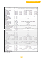
Gas & Venting
Type
Natural GasNatural
Only - LNG
consult factory
Gas Only
Gas Inlet Connection Size
BSP Inch
2 inch BSP - Adapter Required 2" M-BSP to 2" M-NPT
Gas Inlet Pressure Range
In. w.c. [mbar]
Gas Type
NOx emissions [02 = 0%]
Residual Fan Duty
73.5-14/8.5-35
- 14 [17 - 35]
ppm
< 35
In. w.c. [mbar]
0.60 [1.50]
Available In: Room air vertical or horizontial venting - Sealed combustion horizonital or vertical venting arrangements
Flue-Gas Vent Diameter
Inch
10
Combustion Air Vent Diameter
Inch
10
Flue-Gas Mass Range
Maximum
Flue Gas Temperature
Flue
gas temperature
at 104/860F
lb/h [kg/h]
201-999 [91-453]
251-1,246 [114-565]
304-1,499 [138-680]
°F [°C]
149
[65]
126/52
inch
1.25
Heating Return
inch
2.5
Heating Supply
inch
3.0
Condensate Drain Connection
353-1,748 [160-793]
403-2,000 [183-907]
Water
Maximum Water Temp. Safety Limit
°F [°C]
230
[110]
200/93
Water Temperature Operating Range
°F [°C]
68 - 194 [20 - 90]
psig [barg]
11.6 - 100 [0.8 - 6.89] ASME MAWP 100
Water Pressure Range
Gallons
12.9 [49]
15.9 [60]
18.8 [71]
21.7 [82]
24.6 [93]
Water Resistance @ 20°F ΔT [11°C ΔT mbar]
Boiler Water Content [Liters]
Ft. H20 [mbar]
12.5 [374]
12.2 [364]
13.3 [397]
12.2 [364]
13.8 [413]
Water Resistance @ 36°F ΔT [20°C ΔT mbar]
Ft. H20 [mbar]
3.78 [113]
3.68 [110]
4.01 [120]
3.68 [110]
4.18 [125]
24 - 610
24 - 840
Electrical
Main Supply
Power Consumption
120/60/1 - 15A maximum
V/P/H
watt
24 - 370
24 - 380
24 - 470
Rating
IP 20 [NEMA Type 1]
Gas Vent Category
Types
ANSI Z21.13/CSA 4.9 Gas Vent Category II or IV - Special Venting Type BH Only
Combustion Air Temperature
°F [°C]
-4 to 104 [-20 to 40]
Installation Altitude
Ft. [m]
4,500 [1,370m]
IP-IEC-NEMA Protection
Other
Dry Boiler Weight
Floor Area
Noise Level @ 1m [Average]
lb [kg]
Ft2 [m2]
794 [360]
904 [410]
1,014 [460]
12.9 [1.2]
15.1 [1.4]
60
dB(A)
14
1,124 [510]
1,235 [560]
De Dietrich Gas 310/610 ECO
CSA Certified Avg. 97.4 – (potential up to ≅ 99.9%)
95.3 – (potential up to ≅ 99.9%)
3.5-14/8.5-35
126/52
Flue gas temperature at 104/860F
Table 02, Technical data
15
De Dietrich Gas 310/610 ECO
4.3 GAS 310 ECO QUOTATION SPECIFICATION:
Fully assembled cast aluminum floor
standing sectional hot water boiler.
Premix burner with stainless steel
cylinder with perforated holes for precise
air-fuel mixture and velocity with a
stainless tube with woven steel fiber for
stable flame and heat insulation.
Fully condensing boiler.
ASME approved design, CRN for each
Canadian Province.
Precise air to fuel ratio through firing
range with high turn down 5:1.
Boiler comes complete with a digital
combination flame safe guard and a
boiler control, with comprehensive
operating, service and fault diagnostic
capabilities.
Firing capabilities, ON-Off, 2-stage or
fully modulating [0-10v].
Capable of receiving BMS control.
Local-remote control [enable/disable].
Boiler control equipment communication
socket for PC or PDA device used with
OEM software for advanced service and
trouble-shooting diagnostics.
A = Control facing short side or (front)
I = Service side (right or left hand
execution)
Available for conventional chimney with
room or direct vent, CLV and sidewall
vented venting systems.
Fully factory pressure and fire tested.
Distinctive powder coasted enamel steel
removable casing.
Rigid steel boiler frame with castors for
easy maneuvering into boiler’s final
position.
Certified by CSA for USA and Canadian
markets.
High combustion and thermal
efficiencies.
No proven water flow requirements.
No minimum temperature requirements.
Manufactured in an ISO 9001 certified
facility.
Max 100 psi - System water operating
pressure
ASME safety relief valve
Pressure & Temperature gauge
Optional communication protocol
gateway (LonWorks®, BACnet®, etc…)
Lead/lag (cascade) system manager for
up to 8 boilers, space heating pump, 2
mixing valve circuits, 2 mixing valve
pumps, DHW pump.
4.4 Delivery & ordering options:
Available in 5 models
Left or right service side option
2 stage or modulating control
Weather compensator control
Condensate neutralization
system with or without pump
Multiple (Cascade) boiler control
DHW production kit
Vent damper [required for coventing]
Pressure transducer for system
pressure
Low & High gas pressure switch
Gas valve proofing system
Secondary (CSD-1 compliant) Low water cut-off control
Safety relief valve according to system pressure
Combustion air filter
Cleaning tool
Consult factory DDR Americas Inc. [De Dietrich Boilers] for other available options, all orders must specify
if optional controls are to be installed or shipped loose.
16
De Dietrich Gas 310/610 ECO
4.5 GAS 610 QUOTATION SPECIFICATION:
Fully assembled cast aluminum floor
standing sectional hot water boiler.
Premix burner with stainless steel
cylinder with perforated holes for precise
air-fuel mixture and velocity with a
stainless tube with woven steel fiber for
stable flame and heat insulation.
Fully condensing boiler.
ASME approved design, CRN for each
Canadian Province.
Precise air to fuel ratio through firing
range with high turn down 5:1 per unit.
Boiler comes complete with a digital
combination flame safe guard and a
boiler control, with comprehensive
operating, service and fault diagnostic
capabilities.
Firing capabilities, ON-Off, 2-stage or
fully modulating [0-10v].
Capable of BMS control.
Local-remote control [enable/disable].
Boiler control equipment communication
socket for PC or PDA device used with
OEM software for advanced service and
trouble-shooting diagnostics.
2 control orientation versions, service or
short end option.
4.6 Delivery & ordering options:
Available in 4 models
2, 4 stage or modulating control
Weather compensator control
Condensate neutralization system with or
without pump
Multiple boiler control
pressure switch
Gas valve proofing system
Low water cut-off control (CSD-1 compliant)
Safety relief valve according to system pressure
Combustion air filter
Cleaning tool
Available for conventional chimney,
direct vent and sealed combustion
venting systems.
Fully factory pressure and fire tested.
Distinctive powder coasted enamel steel
removable casing.
Rigid steel boiler frame with castors for
easy maneuvering into boiler’s final
position.
Certified by CSA for USA and Canadian
markets.
High combustion and thermal
efficiencies.
No proven water flow requirements.
No minimum temperature requirements.
Manufactured in an ISO 9001 certified
facility.
Max 100 psi - System water operating
pressure
ASME safety relief valve (x2)
Pressure & Temperature gauge (x2)
Optional communication protocol
gateway (LonWorks®, BACnet®, etc…)
Lead/lag (cascade) system manager for
up to 8 boilers, space heating pump, 2
mixing valve circuits, 2 mixing valve
pumps, DHW pump.
DHW production kit
Standard vent damper
Pressure transducer for system pressure
Low gas pressure switch
High gas pressure switch
Accessories must be ordered in pairs, one for each module.
Consult factory DDR Americas Inc. [De Dietrich Boilers] for other available options, all orders must specify
if optional controls are to be installed or shipped loose.
17
De Dietrich Gas 310/610 ECO
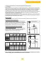
5 EFFICIENCY INFORMATION
5.1 Combustion efficiency
▪ Theoretically efficiency up to 99.9% can be achieved with return water temperature of 104°F
[40°C], the combustion efficiency according to ANSI Z21.13b-/CSA 4.9b-2007 average = 95.3%
5.2 Thermal efficiency [heat to water]
▪ Average thermal efficiency 97.4%
5.3 Standby losses
▪ Less than 0.3% with an average water temperature of 113°F [45°C]
6 APPLICATION DATA
The Gas 310/610 ECO can be used on all new and retrofit projects in both single and multiple
configurations. Conventional and sealed combustion venting system capability means that the boiler can
be sited almost any-where within a building.
External control systems (BMS) can be interfaced with the boiler to provide on/off – high/low or
modulating (0-10 V dc input) firing control options.
7
INSTALLATION INSTRUCTIONS FOR HEATING INSTALLER
7.1 General
All gas appliances must, by law, be installed by competent person (Licensed gas-heating technician)
It is in your own interest and that of safety to ensure that the law is complied with. The following codes
must be adhered to when the De Dietrich Gas 310/610 ECO is installed:
CSA B149 gas installation code & ANSI Z223.1 / NFPA 54 gas code.
In addition to the above regulations, this boiler must be installed in compliance with:
▪ National & local building codes
▪ ASME CSD-1 as required
▪ CSA & NEC electrical codes
▪ Other Regulations
Important:
The De Dietrich Gas 310/610 ECO is a CSA certified boiler and must not be modified or installed in any
way contrary to these “Installation and maintenance Instructions.” Manufacturer’s Instructions must NOT
be taken as overriding statutory obligations.
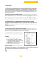
7.2 Delivery and installation
The De Dietrich Gas 310/610 ECO is supplied fully assembled, plastic wrapped and crated on a pallet.
The overall dimensions of the crate are 31.5” [80cm] wide and 68.9” [175 cm] high with the length
dependent on the number of sections (5 & 6 sections: 66.9” [170 cm], 7 to 9 sections: 82.3” [209 cm]).
At the base of the packaging is a 30” [76 cm] wide pallet enabling it to be transported with a pallet truck,
forklift truck or 4-wheel transport boards. Excluding the crate, the boiler is 28.4” [72cm] wide c/w casing
panels and 27 5/8“ [70 cm] without casing and will fit through most standard doors (minimum door
opening width 31.5” [80 cm]. The boiler itself has wheels so that, once the packaging has been removed,
it can easily be moved around on a smooth surface. The packaging lid includes a rocking ramp, which
can be used to negotiate obstacles such as doorsteps and small plinths. Once in position the boiler is
fixed into position using the fitted jacking bolts which both raise the wheels of the ground and level the
boiler. Technical documentation is supplied in a holder on the inside of the boiler casing (beneath the
instrument panel). A number of small loose components, such as the 4 support pads and the siphon for
the boiler have been placed in the flue gas discharge.
The Gas 610 ECO boilers consist of a Gas 310-L and a Gas 310-R. Please refer to page 11 for
details.
18
De Dietrich Gas 310/610 ECO
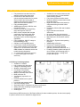
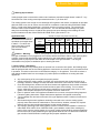
It is advisable (preferable) to install the Gas 310 ECO as follows:
C
C
Place the crate c/w the boiler in the
Single boiler “right hand version”
Single boiler “left hand version”
boiler room. Make sure there is
enough room at one end of the crate
for the boiler and ramp and clearance
for the crate to be removed (at least
10ft [3M]).
Place the 4 support pads under the
adjustment bolts.
Use the adjusting bolts to jack up the
boiler – lifting it clear of the wheels
and with the top of the condensate
collector level.
Fit the siphon assembly.
2 boiler “one right & one left” end to end
Use the plastic packaging to protect
the boiler until required for use.
unit
A
B
C
Service side dimension ‘B’, for servicing it is recommended that an
inch
12
31.5
6
additional 8 inches [200mm] be added, but is not absolutely required.
If the control is orientated to the short end, dimension A will need to
mm 300 800 150
be increased by 19.5 inches [495mm].
At least 16” [400mm] above the boiler
B
A
A
C
C
B
B
C
A
A
E
B
B
B
A
A
2 boiler “one right & one left” back to back
A
A
D
E
6
24
150
600
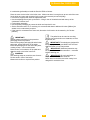
Important!!
Always transport the boiler in the protective packaging whenever possible.
Remove fixing strips, packaging lid and all other packaging, leaving the boiler on the pallet.
Place the packaging lid on the end of the pallet, creating a ramp – secure with screws.
Roll the boiler, on its wheels, off the pallet and down the ramp to the boiler room floor.
WARNING!
Use retaining straps to control the rate of travel – Do Not stand in front of the boiler!
▪ Maneuver the boiler to required final position.
The pallet lid can be used as a rocking ramp to
convey the boiler over obstacles, such as thresholds, etc.
Important!!
The wheels are designed for transport purposes only and
MUST NOT be used when the boiler is in its final position!
Important!!
Additional protection may be required if site conditions
warrant it – overhead builders working, insulation, etc.
Important: Do not install boiler on carpet or other combustible materials. Never stand on the
boiler. The boiler casing is not designed for excessive force or weight.
Boiler base dimensions
Boiler
Model
310-5
310-6
310-7
310-8
A
B
inch
Mm
62
39/64
1590
45
61/64
1980
inch
28
23/64
C
mm
720
inch
2
11/64
D
mm
E
inch
mm
44
1/64
1118
55
59 3/8
310-9
table 03[b] - base - foundation dimensions
19
1508
F
G
inch
mm
inch
mm
inch
mm
5
23/32
145
24
13/16
630
1
25/32
45
De Dietrich Gas 310/610 ECO
It is advisable (preferable) to install the Gas 610 ECO as follows:
Place the crate c/w the boiler in the boiler room. Make sure there is enough room at one end of the crate
for the boiler and ramp and clearance for the crate to be removed (at least 10ft [3M]).
Place the 4 support pads under the adjustment bolts.
Use the adjusting bolts to jack up the boiler – lifting it clear of the wheels and with the top of the
condensate collector level.
Fit the siphon assembly.
Use the plastic packaging to protect the boiler until required for use.
Service side dimension ‘B’, for servicing it is recommended that an additional 8 inches [200mm] be
added, but is not absolutely required.
If the control is orientated to the short end, dimension A will need to be increased by 19.5 inches
[495mm].
The pallet lid can be used as a rocking
ramp to convey the boiler over obstacles, such as
thresholds, etc.
IMPORTANT!
Always transport the boiler in the protective
packaging whenever possible.
Remove fixing strips, packaging lid and all other
packaging, leaving the boiler on the pallet.
Place the packaging lid on the end of the pallet,
creating a ramp – secure with screws.
Roll the boiler, on its wheels, off the pallet and
down the ramp to the boiler room floor.
IMPORTANT!! The wheels are designed for
transport purposes only and MUST NOT be used
when the boiler is in its final position!
IMPORTANT!! Additional protection may
be required if site conditions warrant it – overhead
builders working, etc.
WARNING!
Use retaining straps to control the rate of travel –
Do Not stand in front of the boiler!
Maneuver the boiler to required final position.
IMPORTANT!! Do not install boiler on
carpet or other combustible materials.
Never stand on the boiler the boiler casing is not
designed for excessive force.
20
De Dietrich Gas 310/610 ECO
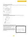
7.3 Flue gas discharge and air supply Venting
any flammable liquids, fluids, vapors or materials
near the vicinity of the boiler.
7.3.1 General
The Gas 310/610 ECO is suitable for both
conventional room-supplied or direct vent
(sealed combustion air) applications. All vent
terminals should comply with the local and
national codes. Any horizontal pipe-work in the
flue gas discharge system should slope towards
the boiler. Horizontal pipe-work in the air supply
system should slope towards the supply opening
and may require a drain point at the low point.
Care should be taken when locating the flue exit
points as a vapor plume will be visible when the
boiler is operational (flue gas temperature can
be less than 170°F [75°C] resulting in the water
vapor condensing upon contact with the air).
Special attention:
Quality of combustion air
Dust, fumes, corrosive elements,
hydrocarbons, other unknown
containments
Paint, beauty, automotive etc. shops
Room combustion air supply requirements:
The boiler must be provided with an adequate
combustion air supply, the combustion air supply
requirements must be determined and sized in
accordance to national and local codes having
jurisdiction. CSA B149 & ANSI Z223.1 – More
than one combustion air source maybe required.
An optional filter should be fitted air intake
housing.
7.3.2 Boiler Venting Types
Flue gas venting material: Use only an
approved gas vent category II and IV type “BH”
Made of AL29-4C® or SS316 as approved. Do
not use PVC-CPVC plastic vent systems.
Air supply venting materials:
Aluminum, galvanized or stainless steel
material, do not used flexible/corrugated
materials.
7.3.3 Venting options
The standard delivery of the De Dietrich Gas
310/610 ECO boiler can be installed with any of
the venting options listed above. See each
respective section for details.
Air supply structure:
The air supply pipe must also be airtight.
Horizontal sections in the air supply must slope
away from the boiler towards the supply opening
and incorporate a drain connection if the route
rises from a lower point. It is necessary to
provide an easily removable air vent for
maintenance reasons from the boiler air intake
connection.
7.3.4 Vent Termination Inlet/Outlets
The vent terminals must be installed to provide
suitable protection against wind, rain, snow or
blockage along with a rodent/debris screen.
See section 7.3.6 & 7 for other requirements.
Conventional chimney application tapered
(finishing) cone, and sidewall or direct vent
applications require a termination TEE or 90°
Elbow fitting.
Conventional Chimney Applications:
(Section 7.3.6)
A vertical chimney-vent system with either room
or direct vent supplied (sealed combustion) air
supply.
Warning:
The flue gas vent pipe must be airtight and
watertight. Horizontal sections of the venting
must slope downward towards the boiler ½” per
linear foot [12mm] and adequate vent support
must be provided.
CLV – Sealed Combustion Systems
Applications: (Section 7.3.6)
A vertical chimney vent system with direct vent
combustion air supply (sealed combustion),
operating at two different pressure zones or vent
terminal locations.
7.3.5 Combustion Air Supply Requirements
The boiler requires a clean, fresh and
adequate supply of combustion air, failure to
provide sufficient combustion air supply will
result in carbon monoxide (CO) production that
could lead to personal injury including loss of life
or damage to boiler or property. Do not store
Sidewall Vented Applications: (Section 7.3.7)
A horizontal venting system for the exhaust and
air intake, the flue gases and combustion air
terminated at same elevation and pressure level,
can be either room supplied combustion air or
direct vented (sealed combustion)
21
De Dietrich Gas 310/610 ECO
7.3.6 Conventional Chimney & CLV Systems Application Requirements:
Warning:
The boiler should never be operated in a negative building pressure. Caution should be exercised with
exhaust fans, air handling & other devices, that could affect the buildings air pressure or combustion air
supply. All venting must be arranged to avoid and prevent the accumulation of flue gas condensation.
An improperly sealed venting system could result in carbon monoxide poisoning; ensure adequate
support and fastening of the system. Ensure venting can safely exhaust all flue gases to the outside in a
safe and effective manner. Do not puncture or drill holes in any portion of the venting, the boiler is
equipped with a pressure and emission test port.
Venting lengths values must be between equivalent lengths show in table 04a-b. Any horizontal runs of
the venting must slope towards the boiler ½” per linear foot. The length in the tables apply to each vent
length separately (air intake and flue gas exhaust)
Exterior Venting:
Any portion of the venting exposed the outside climate shall be suitable for exterior applications.
Conventional Chimney applications:
This venting system uses a single vent to discharge all flue
gases to the outside vertically, combustion air provided with
the boiler room, the air source must be sized in accordance to
national codes CSA B149 & ANSI Z223.1 or local codes
having jurisdiction, more than one source may be required.
á
Not shown air intake filter (recommended)
L = Max
Conventional Chimney with direct vent (sealed
combustion air) applications:
This venting system uses either a co-axle or single vent for
both the air intake and the flue gas exhaust; the boiler room
does not require a combustion air source, as all air for
combustion is taken from the outside source.
Chimney Application [room supplied combustion air]
Vent
Vent
90°
45°
Gas
Length
Length
Elbow =
Elbow =
310/610
Vent ø
[Min]
[Max]
Length
Length
Model
inch mm Ft.
m
Ft.
m Ft.
m
Ft.
m
310-5
310/610-6
310/610-7
10
250
5
1.5 250 76 12 3.5 6.5
2
310/610-8
310/610-9
Table 04[a] - venting length chart. Table also applies to Gas 610 models.
Chimney application with direct vent (sealed combustion air)
Vent
Vent
90°
45°
Length
Length
Elbow =
Elbow =
Gas
Vent ø
[Min]
[Max]
Length
Length
310/610
Model
inc
m
h
mm Ft.
m
Ft.
m Ft.
m
Ft.
m
310-5
310/610-6
310/610-7
10
250
5
1.5 200 60 12 3.5 6.5
2
310/610-8
310/610-9
Table 04[b] - venting length chart. Table also applies to Gas 610 models.
Convention Chimney application with
room supplied combustion air
Gas310 Eco Boiler
[Left hand version shown]
á
à
Fig. 7(a)
L = Max
Convention chimney application with
Direct vent (Sealed Combustion Air) supply
Gas310 Eco Boiler
[Left hand version shown]
Fig. 7(b)
Note: All lengths shown in table 04a-b are for a single boiler only. For multiple boilers (cascade)
common venting systems consult DDR Americas Inc. for assistance.
22
De Dietrich Gas 310/610 ECO
7.3.6 Continued
á
L = Max
L = Max
CLV (different pressure zones) application with
Direct vent (Sealed Combustion Air) supply
à
CLV system application (Different Pressure Zones)
This venting system uses two separate vents that terminate a
different points of the building (2 different pressure zones), a
vent for combustion air and another for the flue gases. All
combustion air is from the outdoor source. The vent terminal
shall discharge flue gases away from the building structure so
that the flue gases do not cause damage to the building. The
vent terminal locations follow local and national codes
requirements. [See section 7.3.9]
Gas310 Eco Boiler
[Left hand version shown]
Fig. 8
Gas 310/610
Model
CLV vent systems venting length chart
Vent
90° Elbow =
Vent Length
Length
Length
Vent ø
[Min]
[Max]
inch
mm
Ft.
m
Ft.
m
Ft.
m
310-5
310/610-6
10
250
5
310/610-7
310/610-8
310/610-9
Table 04[c] - venting length chart.
Table also applies to Gas 610 models.
1.5
180
54
12
3.5
45° Elbow =
Length
Ft.
mm
6.5
2
7.3.7 Sidewall vented application with or without direct vent (sealed combustion air):
Warning:
An improperly sealed venting system could result in
carbon monoxide poisoning; ensure adequate support
and fastening of the system. Ensure venting can safely
exhaust all flue gases to the outside in a safe and
effective manner. Do not puncture or drill holes in any
portion of the venting, the boiler is equipped with a
pressure and emission test port. All venting must be
arranged to avoid and prevent the accumulation of flue
gas condensation.
L = Max
Sidewall vented application with or without
Direct vent (Sealed Combustion Air) supply
áà
Caution – Warning:
Flue gas condensation is very aggressive and corrosive
which could lead to failure of the venting system or
drains, consult local and national codes regarding flue
gas condensation disposal. The P-trap assembly must
be properly filled with water to avoid escape of the flue
gas emissions. The flue gas condensation may require
neutralization prior to entering the drain.
Gas310 Eco Boiler
[Left hand version shown]
Fig. 9
23
De Dietrich Gas 310/610 ECO
Warning & precautions:
Venting lengths must not exceed the minimum and maximum equivalent lengths shown in table 07. Any
horizontal runs of the venting must slope towards the boiler ½” per linear foot.
This venting system uses a single vent to discharge all flue gases to the outside, combustion air provided
within the boiler room, the air source must be sized in accordance to national codes CSA B149 & ANSI
Z223.1 or local codes having jurisdiction, more than one source may be required. The vent terminal
locations follow local and national codes requirements. The vent terminal shall discharge flue gases
away from the building structure so that the flue gases do not cause damage to the building, the vent
terminal locations must also follow CSA B149 & ANSI Z223.1.[See section 7.3.9
Application Note:
The venting must be between
the minimum and maximum
equivalent vent lengths show
in table 5. For values not
show in the chart, consult
your local De Dietrich
Representative.
Gas 310/610
Model
310-5
310/610-6
310/610-7
310/610-8
310/610-9
Sidewall vent length chart [sealed combustion air]
Vent
90° Elbow =
Length
Vent Length
Length
Vent ø
[Min]
[Max]
inch
mm
Ft.
m
Ft.
m
Ft.
m
10
250
5
1.5
65
20
12
3.5
45° Elbow =
Length
Ft.
mm
6.5
2
Table 05 - venting length chart. Table also applies to Gas 610 models.
Caution – Warning:
Flue gas condensation is very aggressive and corrosive which could lead to failure of the venting system
or drains, consult local and national codes regarding flue gas condensation disposal. The P-trap
assembly must be properly filled with water to avoid escape of flue gas emissions. The flue gas
condensation may require neutralization prior to entering the drain.
7.3.8 Co-venting – Retrofitting:
At the time of removal of any existing boiler is removed from a common vent system, the following steps
shall be performed with the each remaining appliance connected to the common vent in operation and not
in operation. This boiler must not be co-vented with a category I or III appliance. The boiler must have a
vent damper installed when in a vent category IV positive pressure installation co-venting with other
appliances.
a. Any used opening of the vent system be properly sealed
b. Visually inspect the venting system for proper size and horizontal pitch, determine there is no
blockage, restriction, leakage, corrosion and other deficiencies could cause an unsafe condition.
c. Close all building doors, windows and all doors between the appliances which remain connected
to the common venting system are located and other space of the building. Turn on clothes
dryers, exhaust fan at maximum speed and any appliance not connected to the common vent
system, close fireplace dampers. Do not operate a summer exhaust fan.
d. Place in operation each of the appliances installed in the common vent system being inspected.
Follow the lighting instructions. Adjust thermostat so appliance will operate continuously.
e. Test for spillage near and around the each of the gas appliances after 5 minutes of main burner
operation.
f. After determining that each appliance remaining connected to the common venting system
properly vents when tested as outlined above, return all doors, windows, exhaust fan, fireplace
dampers and any other gas burning appliance to their normal positions.
g. Any improper operating of the venting system must be corrected so the installation conforms to
either ANSI Z223.1/NFPA 54 or CAN/CSA B149.1 gas installation codes. When resizing any
portion of the common venting system, the common venting system shall be resized to approach
the minimum size as determined using the appropriate tables in Part II of ANSI Z223.1/NFPA 54
gas code &/or CAN/CSA B149.1 natural gas and propane installation code.
24
De Dietrich Gas 310/610 ECO
7.3.9 Vent terminations installation precautions:
[Consult national & local codes for other requirements]
All exhaust terminations for conventional chimney must be finished with a finishing cone with tapered end,
with a bird/rodent screen. All sidewall, direct vent, CLV systems must be finished with either a 90° elbow
TEE termination, the combustion air inlet must be a 90° and must be provided with a debris/bird-rodent
screen. All terminals shall be arranged to avoid prevailing winds and prevent the accumulation of flue gas
condensation.
Warning: In all installations avoid vent termination locations where excessive debris or snow could
accumulate leading to blocking of the vent terminals or where prevailing winds and rain could enter the
vent terminal creating additional resistance to the venting system.
Vent terminals should avoid being installed where the building exterior could be tarnished from the flue
gases, a shield or another location should be considered.
The vent terminals shall be installed according to the instructions as provided terminals shall not be less
than 2 inches [50mm] from the wall surface or more than 10 inches [254mm] from the ℄ of terminal to the
wall. For high traffic locations, the vent terminal shall be guarded.
According to the national gas codes [CSA B149 & ANSI Z223.1/NFPA 54] a vent shall not terminate...
Directly above a paved walkway or driveway which serves two or more buildings or where the flue
gas condensation or vapor could create a hazard or improper operation of regulators, relief’s or
valves or any other device.
Above or below any electric or gas meter, regulators & relief devices unless a 4ft [1.2m]
horizontal clearance distance to be maintained.
Less than 7ft [2.1m] above any paved sidewalk or driveway.
Less than 6ft [1.8m] from any combustion air inlet source from any nearby building.
Less than 4 ft [1.2m] above a meter/regulator assembly horizontally from a vertical centerline of
the regulator vent outlet to a maximum vertical distance of 15ft [4.6m].
Less than 1ft [03m] above grade or normal snow level in the area is expected.
Less than 3ft [0.9m] from windows, doorways, and combustion air supplies nearby buildings or
other appliances.
Under a veranda, porch or deck, unless [1] the veranda, porch or deck is fully open on at least 2
sides underneath. [2] The distance between the top of the terminal and the grade is greater than
1ft [0.3m].
25
De Dietrich Gas 310/610 ECO
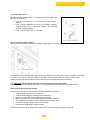
7.4 INSTALLATION DETAILS
7.4.1 Water pressure
The boiler is suitable for a maximum working pressure of 100 psi [6.8 bar], the system pressure shall be at least 12
psi [0.8 bar]
7.4.2 Condensate discharge
Discharge the condensate directly into a drain. Only use synthetic material for the connecting pipe-work because
of the acidity of the condensate (pH 2-5) and allow a min. 1.2 inch per 3 ft. [30mm per meter fall], to ensure a good
gravity siphon flow rate. Fill the siphon with clean water before firing the boiler. It is not advisable to discharge into
an outside gutter because of the risk of freezing. Consult local codes.
7.4.3 Water treatment
The system should be filled with mains, cold water (this will usually have a pH of between 7 and 8). Pressurized
installations with a boiler/system content ratio of 1:10 or less should not require water treatment, provided the
following conditions apply:
1. The system is flushed thoroughly to remove all fluxes and debris and filled completely once.
2. Make up water is limited to 5% per annum.
3. The hardness of the water shall conform to the water quality document requirements
All scale deposits will reduce the efficiency of the boiler and should be prevented. However provided the
above is complied with any scale produced will not be too detrimental to the boiler efficiency and will not reduce the
anticipated life expectancy of the boiler.
7.4.4 Safety valve
A safety relief valve NB certified with V or HV symbol as supplied must be installed on the boiler supply piping
without any obstructions. The relief must be not smaller than ¾” and no larger than NPS 4”; the pressure shall not
exceed 10% above the MAWP and must be of an automatic reset type. The valve opening must be routed away so
that no injury to persons or damage to property will result. Consult local codes. When replacing this safety relief
valve, the relief capacity must be > than the minimum relief capacity as listed on the rating plate.
7.4.5 Water Flow & Content Protection:
The boiler if installed above radiation [heating circuits below the boiler] or as required by local codes or authorities
having jurisdiction must install a low water cut-off safety device.
The boiler has been approved and has found to be in compliance to the LWCO protection, provided the factory preset high limit and flow temperatures are not altered and the modulating controls are used and no minimum flow rate
is required as the ‘abc®’ system will monitor these conditions and reduce the boiler output, finally shutting down
until flow conditions improve. As a result, the boiler is virtually unaffected by low water flow. Although boiler flow
and content protection is provided, does not safeguard the entire heating system, additional low water content and
temperature safety controls maybe needed in certain jurisdictions.
7.4.6 Noise production
The average noise level measured at 3 ft. [1m] distance around the boiler is < 60 dBA at full output, avoiding the
need for additional acoustic measures.
7.5 Multiple boiler installation
The Gas 310/610 ECO can be installed individually or in a multiple boiler installation. The narrow width and depth
of the boiler and its ability to be mounted closely together provides a high output within a small floor area.
26
De Dietrich Gas 310/610 ECO
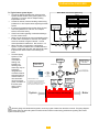
7.6 Typical water system layout
The piping diagram illustrates the minimum boiler
system controls needed, the by-pass system is not
necessary, but can be used in multiple heating
temperature circuits.
Consult all national, local and building codes having
jurisdiction for other requirements regarding the boiler
system.
It is strongly suggested a decoupling devise is used
when the system flow is unknown. For multiple
boilers, consult the factory.
Check local codes regarding condensate discharge
into the common drain.
Water must be analyzed to ensure acceptable quality.
If make water consumption is unknown, the system
should be checked at regular intervals – consult
water specialists for assistance. See section 7.4.3.
When the boiler is connected to a refrigeration
system, it must be installed so the chilled medium is
piped in parallel with the boiler with appropriate valve
to present the chilled medium from entering the
boiler.
The boiler piping
system of a hot
water boiler
connected to
heating coils
Hydrolevel OEM 550
located in air
SafGard LWCO
handling units
where they may be
exposed to
refrigeration air
circulation must be
equipped with flow
controls valves or
other automatic
Installer/Installation note:
means to prevent
The LWCO can be mounted anywhere
gravity circulation of
on the boiler supply piping instead of
mounting on supplied cross tee, must be
the boiler water
within 48 inches be above the boiler.
during cooling
operations.
Boiler Water Connections [Minimum]
Legend
A
Feed Water Main
Boiler Return
H
Pressure-Temp Gauge
I
Safety Relief Valve
Boiler Supply
J
Modulating Sensor
D
Valve
K
Automatic Air Vent
E
Non-Return Valve
3-Way Valve
F
Automatic Fill Valve
L
M
G
Expansion Tank
N
B
C
Heating Circuits
Primary-Secondary
Loop Decoulping
J
K
Pump
Drain
I
H
L
C
M
M
B
A
D
E
F
D
D
N
G
Bell & Gossett
#97 Air vent
Apollo/Conbraco
10-604 or 605 series
relief valves
1 ½ In x 1/8 reducing
bushing for Air vent
1 ½ In x ?? reducing bushing (if
required) for relief valve as required
Relief valve must be piped vertical
1½
Cross
TEE
1 ½ In x ¾ In
reducing
bushing for LWCO
System
Miljilco P/T
gauge
1 ½ in x 2 In.
nipple
Honeywell
L4006E 1067
Safety Hi Limit
Gas310/610 Supply manifold pipe
Boiler
All water piping and reliefs shall be piped to avoid any ingest of water near the boiler controls. The piping diagram
shown below does not reflect all systems consult local and national codes having jurisdictions regarding other water
system controls required.
27
De Dietrich Gas 310/610 ECO
8
INSTALLATION INSTRUCTIONS FOR ELECTRICAL INSTALLER
8.1 General
The De Dietrich Gas 310/610 ECO is supplied as standard with electronic operating and flame ionization safety
controls with a specially designed microprocessor at the heart of the system.
The boiler is pre-wired as shown in the wiring diagram in fig. 18. All external connections can be made on the
terminal strips (one low voltage 24V AC and one main power voltage 120V AC).
Each boiler must be fused protected for a single phase power source 120/1/60 @ 15A, the circuit must be earth
grounded and provided with a service switch that is within hand reach.
Warning – Electrical shock hazard, can cause personal injury or loss of life, including property damage. –
All electrical wiring to the boiler and controls must be protected from ingest of water and be properly grounded and
bonded according to CEC Part I CSA 22.1 & NEC NFPA 70.
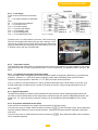
8.2 Electrical specifications
8.2.1 Main power voltage
Each boiler requires a 120V – 1 – 60 Hz supply rated at 10 amps
with line/neutral/earth. The boiler is sensitive to line/neutral and
therefore has a facility to ensure that line and neutral are correctly
connected. If line and neutral are crossed, the display will flash / - alternately.
8.2.2 Control unit
Manufacturer : Honeywell
Type
: MCBA 1458 D
Main voltage
: 120V 60 Hz
Safety time
: 3 sec.
Fig. 13 Position code-key
Each De Dietrich Gas 310/610 ECO has a unique “boiler code.” These codes, together with other data as to boiler
type, counter data, etc., are stored in a “code-key” that belongs to the boiler. If the control unit is replaced this
information remains stored in the code-key.
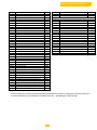
8.2.3 Power consumption
Power consumption at stand-by / part load / full
per boiler unit:
310-5: 12 Watt / 53 Watt / 370 Watt
310-6: 12 Watt / 56 Watt / 380 Watt
310-7: 12 Watt / 45 Watt / 470 Watt
310-8: 12 Watt / 45 Watt / 610 Watt
310-9: 12 Watt / 80 Watt / 840 Watt
load
Fig. 14 control unit
Max boiler module start current 4 amps excluding a
“system pump” if connected to terminal block X27
connections 9 and 10
28
De Dietrich Gas 310/610 ECO
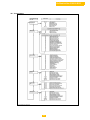
8.2.4 Fuse ratings
Fuses on the circuit board on the control
unit:
F1 – 2 AF mains voltage fuse (automatic
fuse)
F2 – 2 AT for gas valve multiblock
F3 – 2 AT for 24 V circuit
F10 – 2 AT for shunt pump
F11 – 1 AT for flue gas damper
F12 – 1 AT for butterfly valve
F13 – 2 AT for heating pump
F14 – 1 AT for external gas valve
Fig. 15 – Fuse plan
The boiler fuse Fa is located behind / next to the 120V terminal strip.
This fuse de-energizes the whole boiler and has a rating of 10 AT.
The fan has a Power Factor Control (PFC ensures the main power
supply is distributed more uniformly) and is fused with a 12 AT fuse
Fb (behind / next to the 120 V terminal strip).
Fig. 16 – Position fuses (Fa & Fb)
8.2.5 Temperature control
The De Dietrich Gas 310/610 ECO is equipped with an electronic temperature limit control based on flow, return,
and boiler bl ock and f lue gas t emperature s ensors. T he f low t emperature i s a djustable bet ween 68-194°F [2090°C].
8.2.6 Low water level protection (flow and content)
The Gas 310/610 ECO is equipped with low water protection based on temperature differences (∆T) between flow
°
and return. When the ∆T = 45°F [25 C] (factory setting) the boiler starts modulating down so that it remains
°
°
operational as long as possible. When the ∆T = 72 F [40 C] the boiler will be at part load.
°
If the ∆T continues to rise and reaches 81°F [45 C], the boiler shuts down (note a boiler failure, see section 12.4)
and will restart when conditions return to normal. If the boiler is fired dry, it will go to high temperature lock out,
failure code .
8.2.7 High limit protection
The high limit temperature protection device switches off and locks out the boiler (showing a flashing fault code,
see section 14.4 for details) when the flow temperature exceeds the high limit set point (adjustable parameter, see
section 13.2 .10). When the fault is corrected, the boiler can be restarted by using the reset-key on the control
panel.
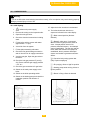
8.2.8 Air pressure differential sensor (LDS)
At the start of the heat demand, the system checks whether the LDS input is open.
If not, there are (max.) 4 restarts, before the boiler is locked out ().If the LDS input is open, the fan will speed
up and a pressure difference is built up across the boiler. When the LDS control speed is reached the LDS input
must close.
If not, there are (max.) 4 restarts before the boiler is locked out (). Once started the LDS function is switched
off for modulation purposes.
29
De Dietrich Gas 310/610 ECO
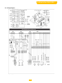
8.3 Connections
The terminal strips and boiler connectors can be seen once the control box cover is removed. The left-hand
terminal strip (X29) is used for 24-volt connections. The right-hand terminal strip (X27) is used for 120-volt
connections. All external connections are made on these terminal strips (see fig. 17). The various connections
options are detailed in the following sections.
Fig. 17 Terminal strip
30
De Dietrich Gas 310/610 ECO
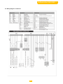
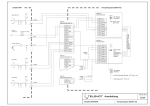
8.4 Wiring Diagram
Fb
12AT
fig. 18 wiring diagram
31
De Dietrich Gas 310/610 ECO
8.4 Wiring Diagram - Continued
32
De Dietrich Gas 310/610 ECO
Field wiring examples (Additional wiring examples are supplied separately)
Example 1, local modulation
LEGEND:
Typical Gas310/610 boiler field wiring
1 Main fuse disconnect
•
•
On/Off control or jumper – modulates according to internal set-point (Connect X29.9 &
X29.10)
LWCO & External Hi-Limit fault attenuation on control, connect devices in series on X29.1 &
X29.2 – Generates fault code flashing numbers requires manual reset of safety
devices first then reset of the boiler control. = Code display & = display
•
•
Optional flow switch application (Start interlock only)
Optional LWCO & Safety Hi limit – can be wired on X29.5 & X29.6 if power failures are
common, note boiler display will not display fault code, but a shut-off code (Flashing
dots)
33
2 Service switch
3 External Hi Limit
4 External LWCO device
5 External Flow Switch
(optional not required)
L
Line 120v
N
L (NC)
L (NO)
Earth ground
Neutral
Output 120v (normally closed)
Output 120v (normally open)
C
Common dry contact
No
Normally open dry contact
Nc
Normally closed dry contact
De Dietrich Gas 310/610 ECO
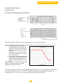
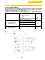
8.5 Switch sequence diagram
8.6 Boiler control
8.6.1 Gas 310 Introduction, Gas 610 each module
Fig. 19 Switch sequence diagram [04.31H.79.00003]
The De Dietrich Gas 310/610 ECO can be controlled using one of the following methods:
Note: When using on/off control the boiler will also modulate to maintain the flow temp set point (parameter )
• Fully modulating, where the output
modulates between the minimum and
maximum value on the basis of the flow
temperature defined by the modulating
controller.
• Analog control (0-10 volts), where the
heat output or temperature is controlled
by a 0-10 volt signal.
• On/off control, (one-volt free relay) where
the heat output modulates between the
minimum and maximum value on the
basis of the flow temperature set in the
boiler.
High/low control, (two volt free relays) where the
boiler is controlled by means of a 2-stage
controller at part load and full load.
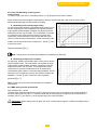
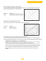
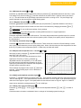
Fig. 20 °output control characteristic
In all cases, modulation is based on the required flow temperature and there is a T dependent output control with
the following characteristic. Up to a T of 45°F [25°C] (factory setting, parameter ) the boiler operates at full
output. Between T full load and T part load the output reduces in linear fashion (see fig. 20).
34
De Dietrich Gas 310/610 ECO
8.6.2 Gas 310 Modulating controls general
(2 wire control)
To make full use of the boiler’s modulating feature, a 0-10v [dc] input control will be needed.
Some controls can provide weather compensation to achieve maximum efficiency and minimum boiler cycling
whilst maintaining design condition within the building.
A. Modulating boiler control [single boiler]
An optional optimizing weather-compensated boiler control can be
used for single boilers. The compensator can regulate the boiler
output against outside weather conditions, and provide time and
temperature control over the DHW. The compensator is mounted
in a reference room (uses an internal sensor to monitor room
temperature) and is interfaced to communicate with the boiler’s
controls via the two wire serial interface. On site connection of the
outside and common flow sensors complete the... Set the value
of the boiler control
Operation parameter to .
Fig. 21 Temperature control via analog (0-10 Volt) signal
Note: Please refer to the control documentation for installation requirements.
B. Modulating multiple boiler controller
An optimizing, weather-compensated boiler control can be used to
control multiple boilers. The compensator can regulate the boiler
output against outside weather conditions, and provide time and
temperature control over the DHW. The multiple boiler controlcompensator is mounted centralized and can be interfaced to
communicate with the boiler’s control the supplied adapter. On site
connection of the outside and common flow sensors complete the
installation. Set the value of the boiler control operation
parameter to .
Note: Please refer to the control documentation for installation
requirements.
Fig. 22 °output control via analog (0-10 Volt) signal
8.6.3 BMS Analog control (0-10 Volt DC)
Input resistance Rim = 66 k.
The heat output modulates between the minimum and the maximum value on the basis of the voltage supplied by
an external analog (0-10V) input. To control the boiler with an analog signal, the signal has to be connected on
terminals X29-11 (+) and X29-12 (-) of the terminal strip in the instrument panel.
Important!!! When analog control is opted, the on/off –contact and the high/low –contact have higher priority
(e.g. frost protection).
35
De Dietrich Gas 310/610 ECO
Gas 310 Temperature based 68 – 194°F [20-90°C]
Set the value of the boiler control operation parameter to . To set the ratio between voltage and the
desired flow temperature (see par. 13.2.5 and fig. 21)
0 to 0.9 Volt
1 Volt
8 Volts
= boiler off
= Flow temperature set point 50°F [10°C]
= Flow temperature set point 176°F [80°C]
Output based – fixed parameters (20 to 100%)
Set the value of the boiler control setting parameter to (see fig. 22)
0 to 1.9 Volt
2 Volt
10 Volts
= Boiler off
= Boiler 20% output
= Boiler = 100% output
8.6.4 On/off control (1 X no volt switched pair) internal modulation
The heat output modulates between the minimum and the maximum value based on the set flow temperature,
terminal connections X29-9 and X29-10. Set the value of the boiler control operation parameter to (on/off).
8.6.5 High/low control 2 stage (2 x no volt switched pairs)
The heat output is controlled between part load (50%, adjustable) and full load by means of a two-stage
controller, terminal connection X29-9 and X29-10 low fire; X29-7 and X29-8 high fire.
Set the value of the boiler control operation parameter to . The output percentage on which the
boiler runs on low fire can be adjusted with parameter (low fire start point as percentage) in the setting
mode. The ‘high fir e’ percentage is dependent of the maximum adjusted output, see setting mode,
parameter (maximum output). During this ‘high’ state modulation on adjusted flow temperature is
released.
36
De Dietrich Gas 310/610 ECO
Gas 610 Temperature based 68 – 194 F [20-90 C] set the value of the boiler control operation
o
o
parameter to . To set the ratio between voltage and the desired flow temperature (see par. 13.2.5
and fig. 21)
0 to 0.9 Volt
= boiler off
o
o
1 Volt
= Flow temperature set point 50 F [10 C]
o
o
8 Volts
= Flow temperature set point 176 F [80 C]
Output based – fixed parameters (20 to 100%), set the value of the boiler control setting parameter
to (see fig. 22)
8.6.6 2-Stage control (2 X no volt switched relays)
The heat output on each boiler module stages between the minimum and the maximum value based on
the set flow temperature, terminal connections X29-9 and X29-10. Set the value of each boiler control
operation parameter to (on/off).
8.6.7 4-Stage High/low control (4 x no volt switched relays)
The heat output is controlled between part load (50%, adjustable) and full load by means of a 4-stage
controller, terminal connection X29-9 and X29-10 low fire; X29-7 and X29-8 high fire.
Set the value of each boiler control operation parameter to . The output percentage on which the
boiler runs on low fire can be adjusted with parameter (low fire start point as percentage) in the setting
mode. The ‘high fire’ percentage is dependent of the maximum adjusted output, see setting mode,
parameter (maximum output). During this ‘high’ state modulation on adjusted flow temperature is
released.
8.7 Other inputs
8.7.1 Shut down input
As standard each boiler module is supplied with a shut down interlock carrying a 24 Volt AC boiler control
circuit. This input does not require manual re-set.
Any external devices required to stop the boiler (e.g. limit switches of throttling valves, minimum gas
pressure switches) should be wired in series and connected to terminals X29-5 and X29-6, breaking the
circuit will activate the safety interlock and put the boiler into a shut-off condition with code . If
this input is being used, the wire bridge must first be removed.
8.7.2 Lock-out input
As standard each boiler module is supplied with a lock out interlock carrying a 24 Volt AC boiler control
circuit. This input requires manual re-set if activated.
Any external devices required to stop the boiler (e.g. maximum gas pressure switch) must be volt free and
should be wired in series and connected to terminals X29-1 and X29-2. Breaking the circuit will activate
the safety interlock and put the boiler into a lock out condition, failure code requiring manual
intervention to re-set it. If this input is being used, the wire bridge must first be removed.
8.7.3 External interlock
As standard each boiler module is supplied with an external interlock carrying a 24 Volt AC boiler control
circuit.
Any external devices required to prevent the boiler from operating (e.g. boiler room ventilation air flow
switch, or butterfly valve end switch) must be volt free and should be wired in series and connected to
terminals X29-3 and X29-4, breaking the circuit will prevent the boiler from starting. Boiler does not go to
lock-out. If this interlock is being used, the wire bridge must first be removed.
37
De Dietrich Gas 310/610 ECO
8.7.4 Other outputs
8.7.5 Analog output
Depending on the option
settings in the service level (see
section 13.2.13), the analog
output signal is able to transmit
the following values: This output
relates to terminals X29-13(+)
and X29-14(-)
Output Signal
[0-10Vdc]
0 Volts
0.5 Volts
1.0 Volts
2.0 - 10 Volts
Description
Boiler off - standby
Alarm
Shut-off
Output between 20 & 100% or Flow temperature
between 68 – 212°F [20 - 100°C]
table 06 - Analog °output signal
8.7.6 Operation signal
As standard the boiler is supplied with internal relays to indicate boiler “Low fire” and boiler on “High fire”.
The relay contacts are volt free and close to confirm operation.
For the “boiler Low fire” signal connect to terminals X27-6 and X27-7.
For the “boiler High fire” signal connect to terminals X27-4 and X27-5.
For On/Off signal (regardless of firing position): Set parameter to 60 in the service level access
Contact load:
• Maximum voltage:
• Maximum current:
120 V
1 A.
8.7.7 Common alarm (Lockout or power ON signal)
Alarm contacts (dry-volt free)
X27.3 (Common) contact
X27.2 (Normally Closed) contact
X27.1 (Normally Open) contact
•
•
For alarm indication status (Boiler Lockout or loss of power), connect remote alarm signal
between X27.3 (Common) and X27.2 (Normally Closed)
For Power “ON” indication status (Normal boiler status), connect remote signal between X27.3
(Common) and X27.1 (Normally Open)
See Section 8.7.6 for operating signal indication (Actual boiler firing signal) connections.
8.7.8 External gas valve control
As standard the boiler is supplied with an internal relay that is energized when there is a heat internal
relay that is energized when there is a heat demand, this applies a 120 V supply to terminals X27-15
(live) and X27-14 (neutral). The relay is de-energized when the gas valve multiblock closes at the end of
the heat demand. Additional external interlocks (by others) may be required in a multi boiler installation.
Important!!! This supply cannot be used to control an external gas valve if it supplies other
appliances.
- External gas valve voltage:
120 Volts
- Maximum current:
1 Amp.
38
De Dietrich Gas 310/610 ECO
8.8 Optional Inputs
8.8.1 System pressure sensor (optional)
The system pressure sensor shutdown the boiler (with shutoff code ) when the minimum water
pressure is reached (adjustable 11-100 psig [0.8 – 6 bar] factory setting = 14.5 psig [bar], see section
12.2.12) the hydraulic pressure sensor must be connected on the 5-pin female plug X22 on the 24-volt
terminal strip. Press the and simultaneously for 2 seconds to indicate the presence of the
pressure sensor in the control.
8.8.2 Gas valve leak proving system VPS (optional)
The gas valve leak proving system checks and operates the safety valves on the gas valve multiblock.
The test takes place before the boiler pre-purge mode. In the event of a leak between the 2 valves in the
gas valve multiblock, the boiler will lock out and show the failure code or on the display. The
gas valve leak proving system must be fitted to the boiler and connected to the 3-pin female plug X21 on
the 24-volt terminal strip and the control set to recognize it using the parameter in the setting mode
(see section 13.2.13)
8.8.3 Minimum gas pressure switch (suitable for gas pressures up t° 14” w.c. [30mbar])
The minimum gas pressure switch (set to 3.5 inches w.c. [8mbar]) shuts down the boiler (shut-off code
) if the inlet gas pressure becomes too low. The minimum gas pressure switch must be
connected to the 3-pin female plug X21 on the 24 –volt terminal strip. The connection is automatically
detected by the boiler control.
8.8.4 Flue gas damper (Gas 310 – optional, Gas 610 - standard)
In a positive pressure vent application, an optional flue gas damper can be installed to avoid hot flue
gases to pass through the boiler during the off periods. A vent damper is required for each Gas 310/610
boiler connected to Cat IV single boiler or Co-vented common venting system.
The flue gas damper [RGK] is wired to the boiler control
with a special 4-pin connector marked X14, the damper is
an 115v – 60Hz operated damper. See wiring on page
25.
Installation:
1. Install vent damper assembly on to the boiler flue
connector observe the flow direction
2. Route vent damper wire harness – supplied in
through the boiler casing channels so that it avoid
contact with any hot boiler components
3. Remove existing jumper on X14 connector on the
boiler control
4. Install the 4-pin from the vent damper
Once the vent damper is installed; the remaining venting
can now be completed.
Confirm the correct operation of the boiler equipped with this vent damper, the damper shall be in its
fully open position prior to allowing the boiler to start the pre-purge phase.
This optional device installed or not does not affect the overall efficiency of the boiler.
Please refer to the document supplied with the vent damper for detailed installation information.
39
De Dietrich Gas 310/610 ECO
8.8.5 Return butterfly valve 3-way valve (supplied by others)
A butterfly valve should be installed in return for each boiler module is hydraulically disconnected from the
system. The return butterfly valve is fully open the valve end switch contact is closed, allowing the boiler
to run. The return butterfly valve must be connected to terminals X21-11 (neutral), X27-12 (power close)
and X27-13 (power open) on the 120-volt terminal strip. The end switch on the return butterfly valve must
be connected to the external interlock terminals X29-3 and X29-4 (first remove bridge). After boiler shutoff, the power supply will remain on X27-13 keeping the valve open during the post purge time of the
pump (set point code , then switch to X27-12 to close the valve (this remains valid even if no pump has
been connected to the control box. (also see sections 8.9.1 & 13.1.2
Please refer to the document supplied with the return of 3-way valve for detailed installation
information.
8.9 Other connections
8.9.1 Boiler or System pump control
The Gas 310/610 ECO a power supply (120V max 2amps) to run or control an external boiler or system
pump. The boiler control will run the pump once every 24hrs when the boiler not enabled to prevent
sticking and will also provide a run on period at the end of a heat demand (parameter , see section
13.1.2)
Important!! Phase/Neutral sensitive!
Important!! For multiple boiler installations the system pump cannot use this power supply.
If the boiler shuts down the system pump will also shutdown.
8.9.2 Frost protection
The boiler must be installed in a frost-free area to prevent freezing of the condensate drain.
If the temperature of the heating water drops too low the integrated boiler protection activates under the
following conditions.
If the boiler flow temperature:
▪ Is below 44°F [7°C], the external heating pump connected to the boiler is switched on at
minimum capacity:
▪ Is below 39°F [3°C] the boiler is switched on at minimum capacity;
▪ Exceeds 50°F [10°C], the boiler and heating pump are switched off again. The pump now
has a fixed post-circulation time of 15 minutes.
Important!!
This frost protection only protects the boiler. Other measures must be employed to protect the
building and system and will depend which parameters are set or what form of external controls
are in use.
40
De Dietrich Gas 310/610 ECO
9.0 INSTALLATION INSTRUCTIONS FOR GAS INSTALLER
9.1 Gas connection
The Gas 310/610 is suitable for use with natural gas only. The gas connection is at the top of the boiler
(see fig. 02). The boiler is fitted with a gas filter as standard to prevent dirt from contaminating the gas
valve or burner assembly. An isolating main gas cocks must be installed in the vicinity of the boiler.
A main gas shutoff valve should be connected to the 2 Inch NPT connection on the boiler, and
must be readily accessible and within hand reach.
Sediment trap must be installed upstream of the main gas cocks shutoff valve.
The boiler fuel train does not require venting to the atmosphere, other regulators and safety
shutoff valves may require venting and relief piping to the atmosphere, consult their
documentation.
9.2 Gas pressures
The boilers main gas valve can accept a maximum inlet pressure up to ½ psi or 14 “w.c. [35 mbar], but
MUST provided with a min. of 3.5 “w.c. [8 mbar] at the gas filter inlet test point when the boiler is
operating at max output. Pressures below this level can result in lockouts (for multi gas appliance
installations this minimum pressure must be available at each boiler with all gas appliances firing on max
output).
Gas system pressure checks:
The boiler main gas cocks shutoff valve and piping must be isolated from any gas piping pressure
testing in excess of ½ psi or 14 ”w.c. [35 mbar]
The boiler main gas cocks shutoff valve and piping must be isolated by closing the main gas
cocks shutoff valve during gas piping pressure testing less than ½ psi [3.5 kPa]
The boiler main gas piping and gas train must be leak tested prior to placing the boiler in
operation
9.3 Gas / air ratio control
The boiler has a pressure differential gas/air ratio control. This gas/air ratio control maintains the correct
balance of gas and air quantities to the burner at a constant level under variable loads. This ensures
clean and reliable combustion and high part load efficiency across the entire load range. Minimum airflow
is monitored before a start by an air pressure differential sensor.
41
De Dietrich Gas 310/610 ECO
10.0 COMMISSIONING
Warning:
If you do not follow the commissioning instructions exactly, a fire or explosion may result causing property
damage, personal injury or loss of life.
10.1 Initial lighting
15. Adjust the boiler controls to heat demand.
1. Isolate main power supply
2. Remove the casing on the inspection side.
3. Open the main gas valve.
4. Check the electrical connections including
earth.
5. Fill the boiler and the system with water
(approximate > 11 psi).
6. Vent all air from the system.
7. Fill the siphon assembly with water.
8. Check the flue gas discharge connection
and air inlet duct or air supply connections.
9. Vent the gas pipe, Open the gas cocks to
the boiler.
10. Check the inlet gas pressure PI (see fig.
23). Ensure sufficient gas supply pressure
> 3.5 “w.c.
11. Check the gas connections for gas leaks.
16. The boiler should start with the run
sequence indicated in the code-display:
= Boiler neutral position (No heat
demand)
= Butterfly valve open, if connected;
Wait for minimum gas pressure switch to
close: Neutral position check of air
pressure differential sensor; Vent damper
opens (if applicable); The fan runs and the
boiler waits until sufficient air transport is
established; the air pressure differential
sensor must switch to guarantee sufficient
airflow.
= Gas valve leak proving system test
(Only if option employed)
= Pre-purging, drives to high fire position
= Heating pump starts running; drives to
ignition position.
12. Switch on the main power supply to the
boiler.
= Burner is firing a flame is detected
13. Switch on the boiler operating switch.
14. Switch on the heating pump and check the
installation position and direction of
rotation.
Fig. 24 flue gas measuring point
Fig. 23 Gas valve (multiblock) adjustments – Artist impression
42
De Dietrich Gas 310/610 ECO
17 Continued:
a. Check and correct, if necessary, the boiler for correct gas/air ratio set-up. Checking takes place on full and part
load, adjustment takes place only on the gas valve multiblock. For checking and adjusting are required: an
electronic CO2-gauge (on the basis of O2) and a gas pressure gauge. Note that the opening (see fig. 24) around
the measuring probe is sealed properly during measurement. Note also that measuring the O2 levels in the flue
gas is necessary, because direct measurement of CO2 can lead to inaccuracies due to varying CO2 levels in the
natural gas. Connect the gas pressure meter between measuring point PG on the underside of the gas valve
multiblock and measuring point PL on the venturi (see fig. 23), ensuring the connections are gas tight.
a. Run the boiler at full load (forced mode ‘high’) by pressing the and [+]-key simultaneously for 2
seconds. The letter will now appear on the display.
b. When full load is reached, measure P gas at measuring point P on the underside of the gas valve
multiblock and at the measuring point PL on the Venturi and compare to the value in table 7 adjust if
necessary using the adjustment screw on the gas valve multiblock.
c.
Check CO2- percentage (O2-percentage) against table 11. If the values exceed the given tolerances,
adjust according to fig. 23. Check the flame through the inspection glass, the flame must not blow off.
d. Run the boiler at part load (forced mode ‘low’) by pressing the and [-] keys simultaneously for 2
seconds. The letter will now appear on the display.
e. When part load is reached, measure P gas at measuring point P on the underside of the gas valve
multiblock and at measuring point PL on the Venturi and compare to the value in table 7 adjust if
necessary using the adjustment screw on the gas valve multiblock.
f.
Check CO2-percentage (O2-percentage) against table 11. If the values exceed the given
tolerances, adjust according to fig. 23.
g. Remove measuring equipment and seal test points.
Check the flame through the inspection glass, the flame must not blow off. Repeat the check starting from
point 17b until the readings match the values in the tables. Contact our Service Department if deviations
cannot be corrected.
Combustion Readings
Full Load
Part Load
Unit
(100%)
(20%)
CO2 Range
%
9.0 ± 0.5
CO2 Set Point
%
9.0 ± 0.15
O2 Range
%
4.8 ± 0.5
O2 Set Point
%
4.8 ± 0.25
CO Limit
ppm
< 100
Emission
Boiler
Models
Gas Pressure Readings*
Full Load (100%)
Part Load (20%)
Δp [in w.c.]
Δp [mbar]
Δp [in w.c.]
Δp [mbar]
310-5
5.20 ± 0.6
13.0 ± 1.5
0.28 ± 0.08
0.70 ± 0.20
310-6
4 ± 0.6
10 ± 1.5
0.18 ± 0.08
0.45 ± 0.20
310-7
3.80 ± 0.6
9.5 ± 1.5
0.20 ± 0.08
0.50 ± 0.20
310-8
5 ± 0.6
12.5 ± 1.5
0.30 ± 0.08
0.75 ± 0.20
310-9
6.20 ± 0.6
15.5 ± 1.5
0.32 ± 0.08
0.80 ± 0.20
* For reference only. Measured combustion values more important.
IMPROTANT SAFETY WARNING:
The installation of the boiler is not completed until all controls and safety device have been tested and
verified for correct function and operation. It is the sole responsibility of the installer to ensure that safety
control system and gas ignition system and any there safety control must be tested.
43
De Dietrich Gas 310/610 ECO
18. Check gas leakage control and minimum gas
pressure switch (if installed); Parameter
must be set to a value greater than or equal to
8, depending on the connected options (see
section 13.2.13). Then set the gas leakage
control pressure switch to a switch pressure
equal to 50% of the inlet pressure. Check that
the measured inlet pressure is not the (higher)
closing pressure.
19. Return the boiler to ‘user level’ by pressing the
reset key.
o
°
20. Heat the system to approximately 176 F [80 C]
and switch off the boiler.
21. Bleed the system and check the water
pressure.
22. The boiler is now ready for operation.
23. Set the boiler controls to the required values.
24. Check all safety controls and ignition systems
for correct operation and safety shutdown
function.
25. Send completed commissioning reports to
DDR Americas Inc.
Note:
The Gas 310/610 ECO is supplied with a number of factory default settings that should be correct for most
installations. If there setting values are required: see sections 13.1 and 13.2.
The following operating situations are now possible:
26.
a. Modulating operation: The output of the boiler modulates on the basis of the flow temperature,
asked by the modulating control (see ‘Note’ in point 25c and section 8.6.2).
b. High/low operation: The boiler is operating at part load or full load, depending on the heat demand
(see section 8.6.5). on the safety boundaries the boiler is going to modulate.
c. On/off operation: the boiler modulates between minimal and maximum output on the basis of the
flow temperature pre-set on the boiler (see section 8.6.4).
d. Important!! The boiler will initially operate in forces part load. The factory setting for forced
part load time is 30 seconds. This setting is correct if modulating controllers are used (see point
25a). A forced part load time of 3 minutes is recommended for on/off operation (setting mode,
parameter , see section 13.2.3).
e. 0-10 V operation: Depending on the adjustments, two situations are possible (see section 8.6.3):
The given off output varies linear with the sent signal, 2V = 20%, 10V = 100%
The given off flow temperature varies linear with the sent signal (depending on parameter and
); example: 0V – 32°F [0°C], 10V = 212°F [100°C].
The boiler modulates on the basis of the set flow temperature (setting range 68-194°F [20-90°C]
and a maximum T protection.
Boiler gas ignition control operation and safety shutdown safety check procedure:
1. Shut off electrical power to boiler
2. Shut off main gas supply cocks valve to boiler
3. Restore power to boiler
6. Observe safety shutdown condition, the boiler
shall shutdown then attempt to restart (max 5
automatic restarts, followed by lock-out code =
and error on control, confirm shutdown
code is correct.
4. Activate heat demand
5. Observe ignition
7. Reset the boiler control
8. Open main gas supply cocks valve
9. Observe ignition and note irregular ignition –
consult maintenance section of this manual
44
De Dietrich Gas 310/610 ECO
10.2 Shutdown
1. Switch off the on/off switch of the boiler. With this, a possible boiler control will be without power.
2. Close the main shutoff valve.
Important!! – No frost protection when the boiler power is turned off
45
De Dietrich Gas 310/610 ECO
11.0 CONTROL AND SAFETY EQUIPMENT
11.1 General
The boiler is supplied with a standard set of defaults pre-programmed for normal operation but can be tailored by
the engineer to suit most site conditions. These values are set and read, using the built-in instrument panel or
with a laptop/computer or PDA (with optional software and interface).
For tamper proofing and security reasons the control has three levels of access:
1. User level
- owner access
2. Service level
- access with service code by qualified personnel
3. Factory level
- access by PC with factory code
11.1.1 Instrument panel layout
The instrument panel consists of (see fig. 25):
1. Operating switch
2. PC/PDA connection for monitoring
3. Facility for incorporating a weather compensator
Fig. 25 Instrument panel
The functions of the keys and read-out windows (a-h) are explained below.
A summary of the key functions can be found in section 16.1 which is helpful when stepping through the
modes.
a. Code window:
Display at user level:
b.
operating mode = only digit or letter
▪
setting mode = digit or letter with steady
dot
▪
▪
read-out mode = digit or letter with
flashing dot
▪
shut-off mode
d.
letter
mode
forced mode = ‘HIGH’ letter
▪
failure mode = flashing digit (current fault)
▪
▪
▪
Key (step key):
- program function; use this key t° select a parameter
within the mode
f.
Display at service level:
▪
key (mode key):
- program function; use this key to select the required
e.
forced mode = ‘L°W’ letter
▪
c.
window displaying:
- temperatures
- settings
- shut-off or failure codes
reset key:
- reset/unlock key
failure mode = flashing digit (failure
memory)
g.
h.
counter mode = alternating + +
shut-off mode = alternating digit and dot in first
section
46
key (stare key);
- program function; increase setting
[+] key:
-program function; increase setting
[-] key:
- program function; decrease setting
- switch function; manual or automatic °operation
De Dietrich Gas 310/610 ECO
11.1.2 LED indicators
The instrument panel has 4 indicating LED’s with the following functions:
▪
The LED above the [-] key (in the symbol); when illuminated green confirms the boiler is in manual
override (see section 11.2)
▪
The LED above the [] key indicates that “24 hour pump operation” has activated the heating pump
(and the shunt pump if required).
▪
The LED above the [+] key flashes if the optional hydraulic pressure sensor detects that the water
pressure is too low.
▪
The LED above the [] key flashes if there is no communication with the code key (code key not
connected).
▪
Two LED’s flash green when there is no communication anymore between code key and control unit.
The boiler will keep on operating. Only after the power supply was switched off and back on, the boiler
will refuse to operate.
11.2 Switch function key
Some keys on the instrument panel have dual functions, i.e. a programming and a switch function.
The programming function is described in section 13.
The switch function (on or off) is activated by pressing down the relevant key for 2 seconds. Whether the function
is switched on or off is indicated by the indicator for the key, which is either lit or not lit, or by the appearance of a
letter in the code window.
11.2.1 Manual/automatic operation
If the [-] key is pressed for 2 seconds the boiler will switch on, even if there is no heat demand from an external
control. The green LED above the key stays on continuously to indicates a manual heat demand (central heating
bridged internally). When the [-] key is pressed for 2 seconds again the boiler will return to automatic central
heating operation (green LED off).
During manual operation the flow temperature cannot exceed its pre-set maximum value. This is to protect
the boiler and the system. Parameters can be changed during manual operations.
Important!! If the external heating pump is not connected to the control unit, the pump will not be switched.
11.2.2 Forced mode ‘high’ ()
By pressing the and [+]-key simultaneously in operating mode during 2 seconds, the boiler will run at maximum
power. The letter will now appear on the display. To protect the boiler and the system, the flow temperature
cannot exceed its pre-set maximum value. This is...Parameters can be changed in this mode. By pressing the
[+]-key and {-}-keys simultaneously, the boiler will return to operating mode.
Following a manual override the boiler will return to normal (auto control) if no keys are used within a 15-minute
period.
11.2.3 Forced mode ‘low’ ()
By pressing the and [-]-key simultaneously in operating mode, the boiler will run at minimum power. The letter
will now appear on the display. To protect the boiler and the system, the flow temperature cannot exceed its
pre-set maximum value. This is... Parameters can be changed in this mode.
By pressing the [+]-key and [-]-key simultaneously, the boiler will return to operating mode.
Following a manual override the boiler will return to normal (auto control) if no keys are used within a 15 minute
period.
47
De Dietrich Gas 310/610 ECO
11.3 Display of value
The display has only two digits available therefore values over this are displayed as followed:
▪ Values from 00 to 99 will be indicated without any decimals points.
▪ Values from 100 to 199 will be indicated by a dot between both digits e.g. =100, =110, =199
▪
Values from 200 to 299 will be indicated by a dot behind every digit e.g. = for 200, =210, =299
▪ Value over 300 will be indicated by showing the thousands, hundreds, tens and units in separate
alternating pairs. (see section 12.2 and 12.5)
▪ Negative values (for instance when using an external sensor or when sensors are not connected) will be
indicated by a dot behind the last digit, e.g. indicates -10.
12.0 OPERATING MODE
12.1 Operating mode ()
During normal operation the code-display show the status (position in cycle) of the boiler, with the -display
indicating the actual flow temperature.
The digits or letters in the code-display have the following meaning:
Code
Description
Standby, there is no heat demand
Pre-ventilation (pre-purge time 30 seconds, post purge time 3 seconds)
Trial for ignition
Burner firing and flame detected
N/a
Waiting mode, startup check, air sensor LDs sufficient pressure
Control stop (burner off + post purge)
a) Flow temperature T1 > set point 9°F [+5°C]
b) Flow temperature T1 > desired set point modulating control 9°F [+5°C]
c) flow temperature T1 > parameter
d) Difference flow T1 and return T2 > 10°C (factory setting) Starting condition is ≤ 10°C
End of heating demand, pump post purge. During cycling prevention delay-time the boiler will
N/a
Shut-off mode (see section 12.4)
Forced full load (HIGH)
Forced part load (LOW)
Gas leakage control
remain in state and will not react to heat demand.
Burner cooling
Table 08
48
De Dietrich Gas 310/610 ECO
12.2 Read-out mode ()
Read-out mode is used to display various values. Press the key until appears in the code window (dot
flashes). Select the required code using the key.
Code
Description
Read-out range/comments
Flow temperature °F [°C]
Actual value
Return temperature °F [°C]
Actual value
Flue gas temperature °F [°C]
Actual value
Heat exchanger temperature °F [°C]
Actual value
Flow temperature set point °F [°C]
Calculated value
= on/off contact closed
Air pressure diff. sensor (LDs, 2nd digit)
= air pressure diff. sensor closed
Switch-on temperature for central heating
operation °F [°C]
Demanded value
Requested (permitted by boiler control) output
% is displayed, irrespective of boiler control
setting
= on/off contact open
Heat demand status (1st digit)
Read-out
(e.g.)
= air pressure diff. sensor °pen
- = 100% demanded value
- = 100% actual value
- = 100% actual value
Control strategy (see section 12.3)
-
Current water pressure
- ÷ 10 bar units, then x 14.5 for
psi units. with pressure sensor (optionally),
N/a
Fan speed
-
Ionization level (flame signal)
- = x 0.1µA
Calculated output %
Analog input voltage - volts
no pressure sensor
then
=
4000*
Unique boiler code
-
Pressure difference over air pressure
differential sensor
- = x 0.1 mbar, then x 0.4 for
inches w.c. units
Table 09 Read-out mode user level
*The displayed value has 4 digits. The display alternately flashes from to with code
indicating the value being read. In this example: fan speed 4000 i.e.
49
De Dietrich Gas 310/610 ECO
12.3 Control strategy
During normal operation, the boiler control can operate
according to a specific strategy. Most control
strategies are meant to keep the boiler burning for as
long as possible, regardless of changes in flow and
flow problems, etc.
The control strategies can be viewed in read-out mode
with the code .
= modulate up (control below ionization limit)
= modulate down (maximum temperature difference
between flow and return)
= minimum output (return temperature higher than
flow temperature)
= modulate down (flue gas temperature too high)
= pump/boiler on (frost protection)
= zero-flow protection 2 (minimum output)
= zero-flow protection 1 (modulate down)
= boiler block temperature too high (control stop)
12.4 Shut-off ()
12.4.1 Shut-off
During shut-off, the code window displays and the
window indicates the shut-off code.
Important!! Shut-off is, a normal boiler
operating function and does not represent a boiler
failure. However, this may indicate a system problem
or an incorrect parameter setting.
12.4.2 Shut-off mode
In shut-off mode last shut-off and corresponding
operating codes can be reviewed. With PC (version
Recom PC and higher) or PDA the last six shut-off’s
can be reviewed.
During this particular mode both dots in the window
flash.
The last shut-off and corresponding operating codes
and applicable temperatures are stored in the microprocessor memory and can be read out in shut-off
mode as follows:
- Enter the service code (see section 13.2).
- Press the key until appears in the code window
(flashing digit with flashing dot).
Select the required step with the key.
Code
Description
Shut-off code (see table 23)
operating code, at shut-off intervention (section 12.1)
Flow temperature, at shut-off intervention
Return temperature, at shut-off intervention
Flue gas temperature, at shut-off intervention
Boiler block temperature, at shut-off intervention
Time from shut-off intervention (PC software °only)
Ionization level (analog), at shut-off intervention
operating hours (hundred thousand, and ten thousand)
operating hours (thousand and hundreds)
operating hours (tens and units)
Fan speed at shut-off intervention (thousands and hundreds)
Fan speed at shut-off intervention (tens and units)
Table 10 Shut-off in service level
The letters and numbers in the code window and the window are explained in appendix 16.2.
50
De Dietrich Gas 310/610 ECO
12.5
Counter mode ( , and ) (service level)
12.5.1 General
The boiler control records various data on the combustion trend of the boiler. This data can be read out in
counter mode. The following data can be read out:
▪ Hours run
▪ Total number of start attempts
▪ Number of shunt pump operating hours
▪ Number of shunt pump starts
▪ Number of internal resets (control unit)
▪ Number of hours energized (control unit)
12.5.2 Reading out counter mode
First enter the service code (see section 13.2).
Press the key until the required code (see table 15) appears in the code window.
Hours run
Number of successful ignitions attempts
Total number of start attempts
Number of shunt pump operating hours
Number of shunt pump starts
Number of internal reset (control unit)
Number of hours energized (control unit)
Table 15 Counter mode codes
The counter has 6 digits. The code window displays the following (in sequence):
st
rd
Code figure, 1 , 2nd , 3 with a value in the window.
Cede figure
Meaning of readout in window
Total number or total number of hours in the hundred thousand and ten thousands
Total number or total number of hours in thousands and hundreds
Total number or total number of hours in tens and units
Table 16 Counter mode readout
Example:
Code window window
value
210000
5700
53
This means 215753 Hours run
51
De Dietrich Gas 310/610 ECO
13.0 SETTING MODE
13.1 User level setting mode ()
Setting mode is used to change various settings to suit individual requirements. The required code is selected by
pressing the key until appears in the code window. Select the required code with the key. Now press
the [+] key to increase a setting or the [-] key to decrease a setting.
Press the key to stare the new setting. The new value will flash twice in the window to confirm the setting.
Cede
Setting range and explanation if
necessary
Description
- = 68 – 194°F or
Flow temperature set point (see
section 13.1.1)
Pump post purge setting
(see section 13.1.2)
Boiler control setting
(see section 13.1.3)
- [20-90°C]
Boiler operating limit set point, also maximum
setting if external control is used.
= 176°F
= 80°C
= Pump post purge = 10 seconds
- = pump run on in minutes
= Pump operates continuously
Control mode (modulating, on/off, etc.)
Table 17 Settings mode user level
Factory setting
Important!! Changing and should only be 0n design engineer’s advice.
13.1.1 Flow temperature ()
The required flow temperature is adjustable from 68-194°F [20-90°C].
The following diagram shows a typical example of this procedure:
Fig. 26 Setting flow temperature
52
De Dietrich Gas 310/610 ECO
13.1.2 Pump run on time ()
Pump run on time can be adjusted (Please refer to
Code
installation contractor)
-Press the -key until the digit (with dot) appears in the
code-display.
-Press the -key until the digit (with dot) appears in
the code-display.
-Set the required value, using the [+] and [-]-keys.
▪ Press the -key to stare the new value (value will flash twice).
▪ Press the reset-key to return to operating mode.
Description
Pump post purge = 10 seconds
Pump purge time for 1 to 15 minutes
( = to )
Continuous pump operation
Table 18 Adjustments pump run on time
13.1.3 Boiler control ()
Setting mode, parameter , can be set to different values
Code
Description
(see table 19).
heat demand off
Proceed as follows to change the boiler control:
Heat demand on
▪ Press the key until the number (with dot)
on/off and High/Low
appears in the code window.
on/off and modulated on flow temperature
▪ Press the key until the letter (with dot)
appears in the code window.
External 0-10v analog signal on temperature
▪ Use the [+] and/or [-] keys to specify the required
External 0-10v analog signal on output %
setting.
▪ Press the key to stare the new setting (flashes twice to confirm).
▪ Press the reset key once to return to operating mode.
Table 19 Boiler control settings.
Example: boiler control indicates that the boiler is controlled by means of a 0-10 volt signal modulated on the
basis of flow temperature (= 4). Heat demand is on ( = 1).
13.2 Setting mode service level (only for the qualified service engineer) ()
To prevent accidental, unauthorized access by non-qualified persons the control system requires an input code to
gain access to the second level of boiler control.
-Press the and keys simultaneously and hold. The code-display now shows a letter with a random
number in the -display.
-While holding both keys pressed, set the -display to , using the [+] or [-] keys and press the key.
-The display will flash twice, confirming acceptance of the access code.
-Release the keys and will disappear from the display.
Important!! Changing the pre-set values without reference to the tables contained in this manual may result
in incorrect boiler operation.
• The service settings can now be reached by pressing the -key until the digit (with dot) appears in the
code-display. Set the required value, using the key.
• To deletes the service code, press the reset-key once.
• If no keys are pressed over a 15 minute period, the service code will delete automatically.
53
De Dietrich Gas 310/610 ECO
Code
Description
Minimum fan speed (hundreds)
see section 13.2.1
Setting Range
Factory setting
- x 100 rpm
310/610-5 = 15 = 1500 rpm
310/610-6 = 16 = 1600 rpm
310/610-7 = 11 = 1100 rpm
310/610-8 = 11 = 1100 rpm
310/610-9 = 12 = 1200 rpm
Minimum fan speed (units) see section 13.2.1
- x 1 rpm
Maximum fan speed (hundreds)
see section 13.2.2
- x 100 rpm
310/610-5 = 5500 rpm
310/610-6 = 5600 rpm
310/610-7 = 3650 rpm
310/610-8 = 4200 rpm
310/610-9 = 4500 rpm
Maximum fan speed (units) see section 13.2.2
- x 1 rpm
Forced part load running time, see section 13.2.3
- x 10 sec.
Cycling prevention delay-time, see section 13.2.4
- x 10 sec.
= 20 seconds
Required flow temperature at 0 volts (analog signal), see
section 13.2.5
- = -58 to 122°F or
Required flow temperature at 10 volts (analog signal), see
section 13.2.6
- , , , = 122 to 480°F or = 212°F or = 100°C
- x 100 rpm
310/610-5 = 3500 rpm
a) Signal "Low fire" if value less than
b) Signal "High fire" if value is greater than
- = 50°C to 249°C
Switch point High/Low operation signal, see section 13.2.6
- = -50°C to 50°C
Shunt pump post purge time, see section 13.2.7
ΔT from control stop point start point, see section 13.2.10
Maximum flue gas temperature, see section 13.2.9
High limit temperature set point, see section 13.2.10
Modulation start point ΔT, see section 13.2.11
310/610-6 = 3900 rpm
310/610-7 = 2500 rpm
310/610-8 = 2700 rpm
310/610-9 = 3500 rpm
= 1 seconds t° = minutes.
= continuous
- = 9 – 54°F
- = 5 - 30°C
= 50 of or = 10°C
- = 176 to 248°F or
= 248 of or = 120°C
- = 194 to 212°F or
= 212 of or
- = 9 to 54°F or
= 45 of or = 25°C
- = 80 to 120°C
- = 90 to 100°C
- = 5 to 30°C
= 100°C
Minimum water pressure, see section 13.2.12
- = x 0.1 bar units or x 14.5 psi units
= 0.8 bar or 11.6 psi
Adjustments options/accessories, see section 13.2.13
-
"Low" fan speed with H/L control parameter =21, see
section 13.2.14
- = x 100
310/610-5 = 1500 rpm
310/610-6 = 1600 rpm
310/610-7 = 1100 rpm
310/610-8 = 1100 rpm
310/610-9 = 1200 rpm
-
depends on output variant
Boiler type; Appears only after replacing the control unit
Table 16 Service level setting mod
54
De Dietrich Gas 310/610 ECO
13.2.1 Minimum fan speed ( and )
Parameter , adjustable between 06 and 60 (x100 rpm) parameter , adjustable between 0 and 100 (x 1 rpm).
This setting is only active if setting has been selected in the boiler control: high/low control (see section
13.1.3). The value relates to the percentage output when the boiler is running at ‘low’. The percentage ‘high’
position depends on the set maximum central heating speed.
13.2.2 Maximum fan speed (and )
Parameter adjustable between 10 and 60 (x100 rpm) and parameter adjustable between 0 and 100 (x 1
rpm).The maximum speed can be limited at a lower value in the software by changing parameters and .
Important!! Do not modify these settings, factory settings.
Important!! Only make changes after consulting DDR Americas Inc. support department.
13.2.3 Forced part load time ()
Parameter adjustable between 0 and 300 seconds. The boiler always starts with a specified output for a certain
time. The boiler can then be sent to the minimum position (20% of output) for a specific period, independent of
the heat demand.
13.2.4 Cycling prevention delay time ()
Parameter () adjustable between 0 and 300 seconds. These values set a minimum off time following a control
stop / end of a heat demand to prevent cycling taking place. When, after this delay time flow temperature lies less
than 9°F [5°C] above return temperature (check °n water flow), the boiler will restart.
13.2.5 Required flow temperature at 0 – 10 volts ( and )
Start point (0 volts): parameter , adjustable between -58
°
°
and 122°F [-50 C and +50 C]
This value sets the required flow temperature at 0-volt
signal input. End point (10 volts): parameter ,
adjustable between 124 and 480°F [+51°C and +249°C
this value sets the required flow temperature at 10-volt
signal input (restricted by the maximum flow temperature
set-point and the maximum output).
These settings only apply if boiler control has been
selected: ‘external analog input 0-10V on the basis of
flow temperature’.
13.2.6 Switch point high/low operation signal ()
Parameter , adjustable between 0 and 60 (x100) rpm. This parameter enables setting the switch point between
“low fire” and “high fire.” A fan speed below the set value will cause a “low fire” signal. A fan speed above the set
value will cause “high fire” signal. A fan speed above the set value will cause a “high fire” signal. An “ON/OFF”
signal can be obtained by setting parameter to 60 = 6000 rpm
13.2.7 Shunt pump post-circulation time ()
Parameter , setting = 10 sec; = continuous and adjustable between and = number of
minutes.
Continuous water circulation is advisable if there is a danger of the heating system freezing up.
55
De Dietrich Gas 310/610 ECO
13.2.8 T from control stops point to start point
Parameter , adjustable from 9 to 36°F [5 to 20°C]
This value sets the flow temperature at which the boiler will cut back in after a control stop.
The boiler will always goes to a control stop when the flow temperature equals the flow set-point temperature >
+9°F [> +5°C] The T defines when the burner is switched on again. A value of 18°F [10°C] indicates the
temperature has to drop 9°F [5°C] below the calculated flow temperature set point before the boiler starts to run
again, cut back in temperature = flow set-point (80) + 5 – parameter (10), i.e. 176 + 9 – 18 = 167°F [80 + 5 –
°
10 = 75 C]
13.2.9 Maximum flue gas temperature ()
Parameter , adjustable between 176 and 248°F [80 and 120°C] This value sets the maximum operating flue
gas temperature – non metallic vent flue systems.
13.2.10 High limit temperature setting ()
Parameter , adjustable between 194 - 230°F [90 - 110°C] This value sets the high limit temperature at which
the boiler will shutdown in a lockout condition requiring manual intervention.
Important!! If the factory setting is reduced, a corresponding reduction in flow set-point will be required
otherwise the min. flow rate may be affected.
13.2.11 Modulation start point at T ()
Parameter , adjustable between 18 and 54°F [10 and 30°C] this value sets the flow/return T point at which the
control modulation begins. The boiler starts to modulate at the set-point and will be at minimum output if the T
continues to rise to 72°F [40°C]. At 81°F [45°C] T the boiler will shut-off (shut-off code ). For
installations with low flow rates the starting point modulation can be brought forward (i.e. 27°F [15°C]), closer
matching boiler output to system demand. In systems with small volume flows the modulation start point can be
brought forward. The boiler is better equipped to anticipate low heat demand. The factory set-point should be
correct for most installations. The setting start point should only be changed if absolutely necessary.
13.2.12 Minimum water pressure ()
Parameter , adjustable between 0 – 58 psi [0 – 4 bar]. This setting only applies if an optional hydraulic pressure
sensor has been connected. This value sets the point at which the boiler will shut-down if the system pressure
falls below it. The boiler will resume normal operation when pressure is restored.
13.2.13 Adjustments options/accessories/units ()
Parameter is adjustable between 0 and 31. This setting is only applicable if options from table 17 are
connected to the boiler. The control unit detects which options have been connected by means of the value of
this parameter and adjusts the boiler control on this basis.
The required feedback message (as output in % or as temperature is °F or °C) can also be selected here if the
(standard) analog output is used. A list of values that have been assigned to specific options can be found in
Adding together the values of the options used gives the parameter setting
56
De Dietrich Gas 310/610 ECO
Example (Factory setting is always = 0)
Options
Boiler water pressure sensor off
Water pressure sensor on = 1
Analog output % = 0
Gas leakage control VPS on = 8
Imperial units of / PSI = 16
Boiler water pressure sensor on
1
Analog output Heat output %
0
▪
▪
▪
▪
Value
0
Analog output Temperature of [°C]
4
Gas leakage control VPS off
0
Gas leakage control VPS on
8
Metric units °C & bar
0
Imperial units °F & psi
16
Parameter :
Sum
…
The sum of these settings provided parameter setting
(1) + (0) + (8) + (16) =
Table 17 adjustment options/accessories
13.2.14 “low” speed with H/L control ()
Parameter , adjustable between 10 and 60 (x100) rpm. This setting only applies if the boiler is in High/Low
control mode (parameter = 21).
13.2.15 Boiler type ()
This code appears only when replacing the control unit. After placing the new control unit, code appears
automatically in the display. The value must be changed in to the correct value for your boiler type (see
mounting-instructions of the service unit
57
De Dietrich Gas 310/610 ECO
14 FAULT-FINDING
Code
Description
Failure code (see table 19)
(section 12.1)
Flow temperature, with failure intervention
Return temperature, with failure intervention
Flue gas temperature, with failure intervention
Boiler block temperature
operating code, with failure intervention
+ Time from failure (with PC software only)
Ionization level (analog)
thousand)
operating hours (thousands and hundreds)
operating hours (tens and units)
hundreds)
Fan speed at failure (tens and units)
operating hours (hundred thousand and ten
fan speed at failure (thousands and
Table 22 Service level failure mode
14.1 General
• If the boiler does not start up, check the
following:
• Is a 120 V supply present?
• Is there a heat demand?
• Has the boiler control (parameter ) been set
correctly ?(see section 13.1.3)
If the above items have been verified and the boiler
does not start, this indicates a failure. In the case of a
failure signal, both the code window and the
window will flash. Except for failure (does not
flash).
Important!!
Keep a record of the failure codes before resetting
(numbers, including flashing digits and dots) and quote
them when asking for technical support or consult the
failure code tables in this manual. The failure code is
needed to find the cause of the fault quickly and
correctly. For further details on the various failure
codes and possible causes refer to table 23.
58
Apart from failure codes (lock-out), the system
also knows shut-off codes (see section 12.4). In the
latter case only the two dots in the window will
flash and the code window will display . A shut-off
code may refer to a system problem or incorrect
setting.
14.2 Failure mode () (service level)
The latest failure and corresponding operating
codes and applicable temperatures are stored in the
micro-processor memory and can be read out in
failure mode as follows:
-Enter the service code (see section 13.2).
-Press the key until appears in the code window
(digit flashes).
-Select the required step with the key.
In the above example:
The return temperature sensor is defective (=failure
code ), during burning (= operating code )
with a flow temperature of 127°F [53°C], return
temperature of 104°F [40°C] and a flue gas
temperature of 136°F [58°C]. The boiler block
temperature was 145°F [63°C], the ionization level was
1.8 A, and the boiler had 118026 operating hours and
a speed of 2667 rpm. The time elapsed after the
failure can only be read on a PC or laptop.
14.3 Cooling mode
This mode enables maintenance on the burner and/or
the heat exchanger to be carried out more efficiently.
In this mode, the fan runs at maximum speed for two°
minutes, which cools down the boiler rapidly. When
this mode is active, the system does not respond to
heat demands.
Important!!
This mode can only be activated if
there is no heat demand on the boiler. The code
indicates that the mode is active ( for cooling).
The mode is activated by pressing the and [+] keys
simultaneously (during normal °operating status with n°
heat demand).
The mode can be terminated prematurely by pressing
the [+] and [-] keys simultaneously.
De Dietrich Gas 310/610 ECO
14.4 Failure (lock-out) codes (requires user intervention, manual reset of control)
When a failure code is displayed, both the code window and the window will flash alternately. Except for
failure (does not flash).
Failure
Description
Flame simulation,
(flame detected in the off position)
Short Circuit in 24v circuit
No flame or ionization signal after 5
attempts
Gas valve multiblock defective
Fuse 3 blown
Cause/check points
- Burner glows as a result of high CO2 percentage (> 10% CO2)
- Check ignition/ionization electrode gap 1/8" or [3-4mm]
Gas valve is leaking or is stuck open, check and replace
Check;
- Wiring to sensors
- Wiring to gas valve
a) N° ignition spark, Check;
- Connection of ignition cable and spark plug cover
- Ignition cable and electrode for breakdown
- For 'flash over' between spark plug cover and earth
- Electrode distance, should be 1/8" or 3.5mm
- Condition of burner set (burner set / electrode seal) earth
b) Ignition spark is present, but no flame. Check;
- The gas main cock valve is open
- There is sufficient inlet gas pressure > 3,5 "w.c. [8.7 mbar]
- The gas pipe has been purge of air
- The gas valve multiblock is energized, during ignition
- The electrode is clean and fitted correctly
- The gas pip is not blocked or fitting correctly
- The air supply or flue gas discharge is not blocked/fitted incorrectly
- The gas/air mixture is set correctly
c) There is flame, but there is insufficient ionization < 2µA, Check;
- The condition of the electrode and earth
- The temperature sensors for leakage current
Control unit does not recognize gas valve multiblock, check;
- The wiring on the gas valve has been disconnected or not fitted
- The gas valve is not defective (burned °out or short-circuit)
Replace fuse 3
Mains voltage has been disconnected during lock out, solution; reset (original lockout usually return automatically)
Fault in control unit or fault due to EMC influences, Reset first if fault persists,
replace control unit. If fault still persists, locate and remove possible external EMC
sources
Check the wiring of the temperature sensors. If fault persists, replace control unit. If
fault still persists, locate and remove possible EMC sources.
Permanently locked out
No processor handshake (or external
influences)
Input failure; sensors are short circuiting
Gas valve multiblock relay fault
Gas valve multiblock defective or not connected.
Air pressure differential sensor does not
maintain check level
Check;
Air pressure differential sensor does not
maintain check level
Fault on internal communication bus
(I2C-bus) when reading EPROM
Locked input open (external safety
controls) LWCO & Hi Limit
Gas multiblock protection
Flow temperature too high
Excessive fan speed
- The air supply or flue gas discharge for blockages/ installation faults.
- The air pressure differential switch and connections
Check
- The multiple wire cable in the instrument panel for short circuit
- Moisture on the display
- Find and remove and EMC sources
- Maximum thermostat (=external protection), connected to terminals X29.1 & 29.2
on the terminal strip, has tripped or jumper has been removed.
- Fuse F3 on automatic burner unit is defective
Gas valve multiblock defective or not connected.
Check;
- Flow
- System as has proper air elimination
- Temperature sensors for deviations
- Water pressure in the system
Check;
- Fan setting parameters
- Fan cable is defective or poor connection, if failure persist fan or control unit may
be defective.
59
De Dietrich Gas 310/610 ECO
- Fan defective
- Fan cable is corroded, resulting in absence of voltage or control signal.
- Check the fan cable connectors on both the fan and the automatic burner unit
side.
- Fan electronics defective
- Excessive negative chimney pressure
Check;
- Flow
- System as has proper air elimination
- Water pressure in the system
Fan not operating
Fan operates continuously or signal
incorrect
Max ΔT exceeded
Temperature sensor fault
Short circuit of flow temperature sensor
Temperature sensor fault
Short circuit of return temperature sensor
Temperature sensor fault
Short circuit of flue gas temperature sensor
Temperature sensor fault
Flow temperature sensor not connected or defective
Temperature sensor fault
Return temperature sensor not connected or defective
Air pressure differential sensor short
circuited
Air pressure differential sensor open
- Check the connecting cable of the air pressure differential sensor
- Air pressure differential sensor is defective or not connected
- Check the air pressure differential sensor connecting cable for short circuiting,
etc.
- Air pressure differential sensor is defective
Temperature sensor fault
Flue gas temperature sensor not connected or defective
one or more parameters are out of limits
The input of the parameter(s) are incorrect
Hydraulic pressure sensor short circuited
Hydraulic pressure sensor open
Maximum flue gas temperature
exceeded
Air pressure differential sensor not
opening
Weak flame ionization signal during
operation (after 4 restarts during 1 heat
demand)
Boiler block temperature too high
Gas leak VA1 (optional)
Gas leak VA2 (optional)
Air pressure differential sensor fault
Boiler block temperature > flow
temperature + hysteresis
Temperature sensor fault
Short circuit of boiler block sensor
Temperature sensor fault
Boiler shut-off sensor is not connected or defective
Boiler block temperature too high
other
codes
Control unit has internal fault
Table 23 Failure codes
- Check the hydraulic pressure sensor connecting cable for short circuit, etc...
- Hydraulic pressure sensor is defective
- Check connecting cable of the hydraulic pressure sensor for short circuit, etc...
- The hydraulic pressure sensor is defective or not connected
Check the heat exchanger for fouling on the flue gas side
Check;
- Is the air pressure differential sensor defective
- Has the wiring been short circuited
- Excessive positive chimney pressure
- Flue gas recirculation, check venting & heat exchanger for leaks
- Insufficient air flow due to blockage
- Check the boiler settings
Check; The heating pump is operating
- There is sufficient water flow through the boiler
- The water pressure is > 11 psi or 0.8 bar
The VPS gas leakage control has detected a leak, Check for external leaks,
otherwise replace gas valve multiblock
The VPS gas leakage control has detected a leak, Check for external leaks,
otherwise replace gas valve multiblock
Air pressure differential sensor fault during pre-purge (after 4 restarts)
Check; Is the air pressure differential sensor defective
- Has the wiring short circuited
- Excessive high positive chimney pressure
Check; - The heating pump is operating
- There is sufficient water flow through the boiler
- The water pressure is < 11 psi or 0.8 bar
Check; - The heating pump is operating
- There is sufficient water flow through the boiler
- The water pressure is < 11 psi or 0.8 bar
Proceed as follows with all non-listed codes
- Press the reset button once
- Check that the wiring is not short circuited
- If the fault persists, contact our service department
WARNING!! Do not reset the boiler control until you can identify and have resolved the problem. Unresolved problems
could cause personal injury or damage to the boiler and controls.
60
De Dietrich Gas 310/610 ECO
15 INSPECTION AND MAINTENANCE INSTRUCTIONS
15.1 General
The De Dietrich Gas 310/610 ECO has been designed to need minimum maintenance, but to ensure optimum
efficiency, we advise that once a year the boiler should be checked and if necessary cleaned and reset. All
service and maintenance must be carried out by a qualified heating contractor with the relevant training and
certifications.
15.2 Cooling mode
This mode enables maintenance on the burner and/or the heat exchanger to be carried out more efficiently. In
this mode, the fan runs at maximum speed for two minutes, which cools down the boiler rapidly. When this mode
is active, the system does not respond to heat demands.
Important!! This mode can only be activated if there is no heat demand on the boiler. The code
indicates that the mode is active ( for cooling).
The mode is activated by pressing the and [+] keys simultaneously (during normal operating status with no
heat demand). The mode can be terminated prematurely by pressing the [+] and [-] keys simultaneously.
15.3 Annual Inspection
The annual inspection of the De Dietrich Gas 310/610 as follows:
▪ Check combustion characteristics, full and part load (see section 10.1)
▪ Note: When checking combustion the CO2 levels should be in accordance with the values in table 11 with a
tolerance of +/- 0.5%. If the levels are outside these tolerances, adjustment to the levels must be made in
accordance with a tolerance of +/- 0.15%.
▪ Check flue gas temperature. If flue gas temperature is more than 86°F [30°C] above the boiler return water
temperature the heat exchanger must be cleaned (see section 15.4.5).
▪ Check/clean the condensate siphon (refill with clean water).
▪ Check for leaks (waterside, flue gas side and gas soundness).
▪ Check flue and air inlet system is clear and gas/water tight.
▪ Check system pressure.
▪ Check control settings.
▪ Check ionization level, minimum 3 A dc (see 12.2, parameter ).
If ionization level < 3 A dc or is not present, check:
▪
▪
▪
▪
▪
▪
▪
▪
▪
Is flame shape stable and color as described in
commissioning instructions?
Check ignition probe earth.
Check condition of ignition/ionization probe
replace if necessary.
Replace electrode at least every 2 years.
Clean any oxides/deposits with sandpaper or
fine emery cloth.
Check shape of probe and ignition gap, i.e. 3 to
4 mm (see fig. 36).
Check temperature sensors for resistance
values against fig. 28 (temp vs. resistance on
sensors).
Check and clean if necessary the gas filter (see
section 15.4.10).
Check air box and dirt trap (see section 15.4.1).
61
Fig. 28 Sensor resistance graph
De Dietrich Gas 310/610 ECO
15.4 Maintenance
If during the annual inspection combustion results indicate that the boiler is no longer operating at the optimum
level additional maintenance should be carried out as follows:
The Gas310/610 ECO boiler or any of its components does not contain any crystalline silica.
Warning – Electrical Shock Hazard:
Please label all wires prior to disconnecting when servicing this boiler. Wiring errors can cause improper operation
and dangerous operation. Verify boiler operation after service!!
Note:
Please ensure that the gas supply and main power supply is isolated before any maintenance work is carried out
on the boiler. Care should be taken when stripping the boiler for maintenance making sure that all parts, nuts,
washers and gaskets, etc. are kept safe, clean and dry for re-assembly. Following maintenance/cleaning, the
boiler should be re-assembled in the reverse order re-placing gaskets and joints where found necessary.
All general cleaning should be carried out with compressed air, a soft brush or damp cloth to avoid
damaging components. (Solvents must not be used).
Remove front and end casing panels – lift casing panel slightly upwards and tilt toward you lift again clear of the
bottom rail.
15.4.1 Inspection of air box and dirt trap
The air box has a dirt trap on the inlet side. Check this for dirt, leaves, etc. If the boiler is closed, the clamping
strip under the casing must be removed first, check using a mirror if necessary.
Check the air box for dirt using a lamp. If the air box is dirty, it must be dismantled and blown clean. If the air box
is dirty, the following components must also be dismantled and blown clean:
▪ non return valve
▪ venturi
▪ fan
Important!! Ensure the balancing clips in the impeller stay in place!
Important!! The sealing between the burner and the mixing blend may be sticky. Prevent the sealing from
tearing. Damaged or hardened sealing must always be replaced.
15.4.2 Cleaning the non return valve
Use compressed air or a synthetic brush to clean the
non return valve.
Fig. 29 non return valve being cleaned with soft brush
15.4.3 Cleaning the Venturi
Use compressed air or a synthetic brush to clean
Venturi. Make sure that the hose between gas valve
and Venturi is clear and in good condition.
Fig. 30 Venturi being cleaned with compressed air
62
De Dietrich Gas 310/610 ECO
15.4.4 Cleaning the fan
Use compressed air or a synthetic brush to clean the fan, be careful
not to disturb the balance clips on the vanes.
Fig. 31 fan being cleaned with soft brush
15.4.5 Cleaning the heat exchanger
Release the retaining nuts from heat exchanger cover plate,
remove plate, being careful not to damage the gasket, store safely.
Heat exchanger can be washed with clean water, if badly
contaminated, clean with a small stiff bristle “bottle type” brush or
use the special cleaning tool (supplied optional). Care should be
taken when using water in the confined space of the boiler casing
to avoid contaminating the electrical controls. Compressed air can
also be used but care should be taken to ensure disturbed dust,
etc, does not contaminate the rest of the boiler and controls.
Replace the heat exchange plate after cleaning and retighten the
retaining nuts.
Fig. 32 – Heat exchanger opened for cleaning.
15.4.6 Cleaning the burner assembly
Clean the burner assembly by using compressed air only – between 30 – 70 psi [2-5 bar] with the nozzle
positioned a min of 3/8” [10mm] away and towards the face of the burner. Check the retaining bolts are tight. If
the burner is removed from the front plate ensure burner-retaining screws are tight on re-assembly
Fig. 33 – Burner cleaning with
compressed air and/or soft brush.
63
De Dietrich Gas 310/610 ECO
15.4.7 Cleaning the condensate collector
Clean the condensate collector by removing the inspection cover (next to the flue gas discharge) and then rinsing
the collector with water
Fig. 34 – Condensate collector inspection
15.4.8 Cleaning the siphon
Remove the complete siphon (located underneath condensate collector beneath the flue connection).
Remove siphon, clean and refill with clean water and re-fit.
Fig. 35 – Condensate siphon assembly
15.4.9 Cleaning/Replacing the Ignition/Ionization electrode
Remove safety bracket from the heat exchanger then remove the two retaining screws on the electrode
assembly, remove assembly and examine for wear and
dirt, clean and re-gap electrode 1/8” [3mm] re-fit if in good
condition (replace gasket if necessary).
Replace electrode assembly if necessary – then discard
screws and gasket and fit replacement assembly c/w new
gasket and screws making sure that the earth connection is
in good condition and in contact with the base plate and refit safety bracket.
Fig. 36 – Ignition/ionization electrode
64
De Dietrich Gas 310/610 ECO
15.4.10 Gas filter check
Measure the pressure differential P at measuring points, Pi and Pu (see
fig. 37) on the gas filter.
• If the P value is above 4.0” w.c. [10 mbar]: gas filter must be
replaced.
• If the P value is between 2.4 - 4.0” w.c. [6-10 mbar]: measure
outgoing pressure on Pu. If this value is below 7” w.c. [18 mbar]:
gas filter must be replaced.
• If the P value is below 2.4” w.c. [6 mbar]
Fig. 37 – Gas filter measuring points
15.4.11 Inspection glass cleaning
Remove the two retaining screws on the inspection glass holder, clean and replace.
Fig. 38 – Flame inspection port removal
Re-assemble boiler in reverse order, check front plate gasket and insulation piece, replace if required. Also check
the gasket on fan and on gas valve, replace if necessary. Ensure that all cables are routed correctly using
existing clips and ties were possible to ensure that they do not touch any hot parts of the boiler.
Important!! Ensure that wires do not come into contact with hot boiler parts
Commission boiler in accordance with section 10.1; complete site report and/or boiler log book if present
Other items requiring periodic checks:
At least once a year the must be checked, cleaned or replaced as required:
Venting system leaks or poor connections
Venting system sagging or damaged vent components
Debris in vent terminal screens [exhaust and air inlet]
Boiler room kept clear of flammable liquids, combustible materials,
The combustion air supply source(s) clear without any obstructions
Combustion air filter if fitted, replace as necessary
Inspection of combustion air supply venting
Additional boiler check list or routine boiler maintenance checklist has been provided on page 66
65
De Dietrich Gas 310/610 ECO
15.5 Exploded view and spare parts list (right hand version shown)
66
De Dietrich Gas 310/610 ECO
Fig. 39 Exploded view
Part #
S100410
S100411
S100412
S100413
S100414
58816
58042
S100415
S100416
S100417
S100418
S100419
S100420
S100421
S100422
S100423
49427
57800
54565
54568
58606
S14254
S100424
S100425
S100426
S100427
S100428
S100429
S54500
S57699
S54501
S44698
S54583
S45004
S100430
S100431
54525
54526
54584
54563
S100433
183
42859
62346
54527
S54822
54528
S54585
25696
58462
S100434
30629
Description
boiler casing/frame
Casing top panel 6 sections
Casing top panel 7 sections
Casing top panel 8 sections
Casing top panel 9 sections
Casing top switch instrument end
Clamp band 260mmØ
Bracket 2"
Front and rear casing panel 5 or 6 sections
Front and rear casing panel 7,8 and 9 sections
Front and rear casing panel (grey)
End casing panel right hand connections
Casing panel handle
Set casing plinths 5 and 6 sections
Set casing plinths 7,8 and 9 sections
End casing panel
Set casing corner posts (set of 4)
Documentation holder A4
Main wheels with axle
Base frame 5 and 6 sections
Base Frame 7,8 and 9 sections
Caster wheel (steering)
Sheet-metal screw 4, 2x9, 5 (20 pc's.)
Front and rear casing panel 5 and 6 secs.
Front & rear casing panel 7,8 & 9 sections (red)
Front and rear casing panel
Casing support 5 & 6 sec.
Casing support 7, 8, 9 sec.
Casing support central
Boiler heat exchanger
Section right hand end
Section intermediate
Section left hand end
Temp. sensor; return, block & flow NTC 12K/007
Electrode ignition/ionization
Glass inspection c/w gasket & 2 screws
Flange blank return
Flange blank flow
O-ring Ø 107 x 5mm
O- ring 81,92 x 5,33
Cover plate
Gasket for electrode ignition/ionization
Supply pipe
Bolt M12X40mm
Nut flange M12
Dowel Ø12 x 20
Stud M12
Mounting frame (for Inspection glass)
Gasket for cover plate/burner
Cover plate for burner hole
Silicone sealant rtv 106
Dowel burner
Return pipe
Sealing silicone red 7 mm (per meter)
Item
#
1001
1001
1001
1001
1001
1004
1005
1006
1006
1007
1008
1009
1010
1010
1011
1012
1013
1014
1015
1015
1016
1017
1019
1019
1020
1021
1021
1022
2001
2002
2003
2004
2005
2006
2007
2008
2009
2010
2011
2012
2015
2016
2017
2018
2019
2020
2021
2022
2023
2024
2025
2027
67
Part #
S100441
S100442
S100443
S100444
S100445
S100348
S100347
S100331
S100329
S100330
S54593
S54591
S54592
S54512
S54513
S54517
S100487
S100460
S59202
S59203
S59204
S59738
S44483
S14254
22222
S100446
S100447
S100448
S100449
S100450
S100451
19609
40139
1035
54549
51163
S100452
58603
S15524
S59818
54595
54528
58622
42859
141
S100453
S59651
59652
59638
58609
S46687
54580
S59650
Description
Premix burner
Valve gas multi block 5 sections
Valve gas multi block 6 sections
Valve gas multi block 7-8-9 sections
Fan 5-6 sections
Fan 7-8-9 sections
Burner for 6 sections
Burner 5 sections
Burner 9 sections
Burner 7 sections
Burner 8 sections
Venturi assembly 7-8-9 sections
Venturi assembly 5 sections
Venturi assembly 6 sections
Venturi connecting piece Ø 130 mm
Venturi connecting piece Ø 100 mm
Air intake damper Ø100 mm with o-rings
Gas filter Dungs 1½"
Air differential pressure switch - Vent safety
Tube gas test point
Tube air pressure test point
Tube pressure compensation test point
Air box 7, 8 and 9 sections
Nut M 8 (10 pc’s.)
Sheet-metal screw 4, 2x9, 5 (20 pc’s.)
Bolt M6x16
Air box
Pipe gas supply 5 sections
Pipe gas supply 6 sections
Pipe gas supply 7 sections
Pipe gas supply 8 sections
Pipe gas supply 9 sections
Pressure test nipple ¼"
Adapter 1.½"x1.¼"
Pressure test nipple 1/8"
Adapter 1.¼"
Gasket Ø 56x42x2
Gas supply pipe 1.¼" w/ Test firing valve
Gasket for venturi
Bolt M 8 x 16 (10 pc’s.)
Nut M 8 (20 pc’s.)
O-ring Ø 142 x 3,5mm
Gasket for cover plate/burner
Bracket plug cap guard
Nut flange M12
Bolt M8 x 30mm
Mixing chamber/pipe
Gasket fan 7,8 and 9 sections
O-ring Ø 180 x 3,5mm
Bolt flange M5 X 20
O-ring Ø 111 x 4mm
Nut flange M5 (10 pc’s.)
Fan adapter plate 5-6 sections
Gasket fan
Item #
3001
3001
3001
3002
3003
3004
3004
3004
3004
3004
3005
3006
3006
3007
3008
3009
3010
3046
3012
3013
3014
3015
3016
3017
3018
3019
3020
3020
3020
3020
3020
3021
3022
3023
3024
3025
3026
3027
3028
3029
3030
3031
3032
3033
3034
3035
3036
3037
3038
3039
3040
3041
3042
De Dietrich Gas 310/610 ECO
S54520
S54521
S54522
S54523
S54524
53544
55558
S54538
S54539
S54540
S54541
S54542
593
S54533
S54534
S54535
S54536
S54537
22222
S54548
S49297
54598
S54529
54562
S100435
S100436
S100437
S100438
S100439
S58818
S58611
54587
S100114
S100440
S48950
113324
113323
113325
113327
113326
S59727
S58823
Access plate heat exchanger 5 sections
Access plate heat exchanger 6 sections
Access plate heat exchanger 7 sections
Access plate heat exchanger 8 sections
Access plate heat exchanger 9 sections
Stud M8x20mm
Nut M 8
2nd return water pipe blind 5 sections
2nd return water pipe blind 6 sections
2nd return water pipe blind 7 sections
2nd return water pipe blind 8 sections
2nd return water pipe blind 9 sections
Plug no. 290 3/8"
Return water distribution pipe 5 sections
Return water distribution pipe 6 sections
Return water distribution pipe 7 sections
Return water distribution pipe 8 sections
Return water distribution pipe 9 sections
Bolt M6x16
Flue gas connection Ø 250mm
Sensor flue gas temperature NTC 12kohm 3%
Sealant silicone red 7 mm L=790mm
Inspection cover (condensate collector)
Sealant silicone red 10 mm per meter
Condensate collector 5 sections
Condensate collector 6 sections
Condensate collector 7 sections
Condensate collector 8 sections
Condensate collector 9 sections
Hose PVC 27/19
Siphon assembly complete
Bolt M12 X 180mm
Washer Ø 13mm (20 pc’s.)
Pipe 5 sections
Screw M4 x 10 (50 pc’s.)
Insulation front plate heat exchanger 6 sec.
Insulation front plate heat exchanger 5 sec.
Insulation front plate heat exchanger 7 sec.
Insulation front plate heat exchanger 9 sec.
Insulation front plate heat exchanger 8 sec.
Flue gas damper MUK Ø 250mm.
Cleaning device L = 560 mm.
2028
2028
2028
2028
2028
2029
2030
2031
2031
2031
2031
2031
2032
2033
2033
2033
2033
2033
2034
2035
2036
2037
2038
2039
2040
2040
2040
2040
2040
2042
2043
2044
2045
2046
2047
2050
2050
2050
2050
2050
2098
S100488
S58602
S58604
S100454
S43563
S43561
S59208
S100455
S59430
S101528
S59429
S100456
S59245
S100457
S100458
S100459
S59238
S100419
57350
S57010
59436
S38187
Adapter 2" NPT (Gas inlet pipe)
Air-pressure sensor Huba 4030
Gas leakage control or gas pressure control
Control
Control board MCBA
Fuse glass 2 amp fast (10 pc’s.)
Fuse glass 2 amp slow (10 pc’s.)
PC board display
Cable set complete wiring harness
Main fuse10A slow acting (5 pc’s.)
Fan/Blower Fuse 12A slow acting (5 pc’s)
Fuse holder FPG2
Flat cable
On/off switch (5 pc’s.)
Ignition/ ionization cable with cap & grommet
Front cover instrument panel
Top cover instrument panel
Cover plate compensating controller
Casing panel handle
Screw control cover m4 x10
Spacer (10 pc’s.)
Cable Flue gas damper (option)
Fuse 1 amp slow acting (10 pc’s.)
3045
3011
310/6100
4001
4001
4001
4002
4003
4003
4003
4003
4004
4005
4006
4007
4008
4009
4010
4011
4012
4096
4001
Please contact your local De Dietrich Authorized Representative or Dealer for spare parts, pricing and delivery, if
you do not know who your local dealer is, DDR Americas Inc. – De Dietrich @ 1.800.943.6275
68
De Dietrich Gas 310/610 ECO
16 ADDENDICES
69
De Dietrich Gas 310/610 ECO
16.1 Control menu
Fig. 40 Control menu flow chart
70
De Dietrich Gas 310/610 ECO
16.2 Shut-off codes
71
De Dietrich Gas 310/610 ECO
16.2 Shut-off codes (Continued)
Table 25 Shut-off codes
72
De Dietrich Gas 310/610 ECO
17 BOILER COMMISIONING REPORT & MAINTENANCESCHEDULE
17.1 – Boiler Commissioning Report
LOCATION OF INSTALLATION
Address
Province or State
City-Town
Mail Code
Installer
Country
Phone #
E-Mail
Company
Phone #
EQUIPMENT DETAILS
Boiler Model
Serial #
Burner Model
Serial #
Control Model
Serial #
Firing
Relief Valve
Size
Capacity Mbtu/h
Chimney Type
Size
LWCO Device
Vent Safety Device
Size
Shunt Pump
Other Controls
FLUE GAS EMISSIONS
Input Rate Gph or MBtu/h
Fuel Type
Item
Min Rate
Min
Min
Min Rate
Max Rate
Max Rate
CO2 & O2 [%]
Air Setting - Index
Head Setting - Index
CO [ppm]
Supply Pressure In. w.c. or psig
NOx [ppm]
Fuel Pressure In. w.c. or psig
Smoke-VOC-PM10
Breech Pressure In. w.c. [mbar]
Ambient [°F or °C]
Chamber Press. In. w.c. [mbar]
Flue Gas Temp. [°F-°C]
Supply-Return Temp [°F or °C]
Gross Combustion Efficiency [%]
Control Safety Checklist
Item
Set Point
Tested
Note
Safety Hi-Limit
Hi-Limit
Operating Limit
LWCO
LGP switch
HGP switch
Vent Device
Aux. Safety
Analyzer Print-outs
To successfully activate the boiler warranty a copy of this startup report must be returned to us to keep on file.
Mail:
DDR Americas Inc.
1090 Fountain Street, North, Unit 10
Cambridge, Ontario, Canada N3E 1A3
Attention: Service Manager
Email: [email protected]
Website: www.dedietrichboilers.com
Facsimile: 519.650.1709 Tel: 519.650.0420
73
De Dietrich Gas 310/610 ECO
17.2 Boiler Control Settings
Site Applied Boiler Control Settings: [Setting Mode]
Advanced Setting Mode – Service Level
17.3 Routine Boiler Maintenance Checklist [Typical] – Does not respect all installations, guideline °only
Responsible
Owner should at least be
familiar with what items
or areas need periodic
attention and
maintenance, the
licensed and authorized
service personnel shall
inform the owner what
symptoms to be aware
of and course of action
Description
Schedule
System pressure 11 – 100 psi
Control functioning
Seals or evidence of leaks
Monthly
Monthly
Monthly
Unobstructed combustion air supply, no
chemicals, garbage, gasoline, other combustible
materials or flammable liquids are stored near the
boiler.
Check for water on the floor – around relief, vent
and other parts and piping of the water system
Check operating limits for correct operation
Ensure neutralization system is working
Check exhaust terminals for ice, snow or debris
buildup
Check and test pressure relief safety valve
Check PH levels of condensate
Test temperature Hi limit functions
Monthly
Monthly
Semi-annually
Semi-annually
Monthly
Annually
Annually
Annually
Checks for system leaks
Check all auxiliary and other safety limits for
function and correct operation.
Check system water quality
Check pump °operation
Check fuel lines for leaks
Check combustion
Check control settings
Clean combustion chamber
Monthly
Monthly
Annually
Annually
Annually
Annually
Clean condensation collector and siphon
Annually
74
Monthly
Annually
DDR Americas Inc.
1054 North DuPage Avenue
Lombard, Illinois 60148 USA
Tel: 630-953-2374 / Fax: 630-953-2376
1090 Fountain Street North, Unit 10
Cambridge, Ontario N3E 1A3 Canada
Tel: 519-650-0420 / Fax: 519-650-1709
Toll Free: 800-943-6275
www.dedietrichboilers.com
[email protected]
G310E 01 v1.0 04/2010