1
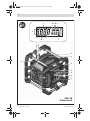
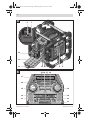
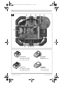
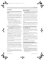
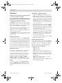
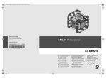
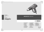
OBJ_BUCH-1181-001.book Page 1 Monday, March 1, 2010 12:05 PM Vo Ba lum ss e Treb Eq M Po we rB ox ua liz em or er y Cus to m Clo ck + Tu ne – – Se ek Se ek So + ur ce BB AA Robert Bosch GmbH Power Tools Division 70745 Leinfelden-Echterdingen Germany GML 20 Professional www.bosch-pt.com 1 609 929 W27 (2010.03) T / 318 UNI de en fr es pt it nl Originalbetriebsanleitung Original instructions Notice originale Manual original Manual original Istruzioni originali Oorspronkelijke gebruiksaanwijzing da Original brugsanvisning sv Bruksanvisning i original no Original driftsinstruks fi Alkuperäiset ohjeet el tr pl cs sk hu ru Πρωτότυπο οδηγιών χρήσης Orijinal işletme talimat Instrukcja oryginalna Původní návod k používání Pôvodný návod na použitie Eredeti használati utasítás Оригинальное руководство по эксплуатации uk Оригінальна інструкція з експлуатації ro Instrucţiuni originale bg Оригинална инструкция sr sl hr et lv lt ar fa Originalno uputstvo za rad Izvirna navodila Originalne upute za rad Algupärane kasutusjuhend Instrukcijas oriģinālvalodā Originali instrukcija ΔϴϠλϷ ϞϴϐθΘϟ ΕΎϤϴϠόΗ ̶Ϡλ έΎ̯ ίήσ ̵ΎϤϨϫέ OBJ_BUCH-1181-001.book Page 3 Monday, March 1, 2010 12:07 PM 3| a b c d e f g h i j k n m l 1 2 1 1 Vo Bas lum s Tr e eb Eq Po we rB ua M lize ox 1 3 r Cu sto m em ory Clo ck + Tu ne – ee k Se ek So + A –S urc e 4 BB 5 GML 20 Professional 1 609 929 W27 | (1.3.10) Bosch Power Tools OBJ_BUCH-1181-001.book Page 4 Monday, March 1, 2010 12:07 PM 4| A 6 7 REPLACE AA BATTERY WHEN UNIT NO LONGER KEEPS CORRECT TIME. E LINT OU V 12 X AU IN 1 B ia ed lM ita Dig ay 14 13 12 11 10 B 9 8 15 16 17 18 27 PowerBox 26 + 25 Volume Bass Treb Equalizer Memory Custom Tune Clock – 24 23 20 – Seek Seek + Source 1 609 929 W27 | (1.3.10) 19 21 22 Bosch Power Tools OBJ_BUCH-1181-001.book Page 5 Monday, March 1, 2010 12:07 PM 5| C 28 29 30 AUX 1 IN IN SD / MMC 36 31 32 LINE LI L LIN I IN OUT 250V 1AMP FUSE FOR 12V OUTLET USB AUX 2 IN 35 34 31 33 14,4 V (Li-Ion) 2 607 336 150 (1,3 Ah) 2 607 336 078 (2,6 Ah) 2 607 336 224 (3,0 Ah) AL 1820 CV (14,4/18 V) 2 607 225 424 (EU) 18 V (Li-Ion) 2 607 336 170 (1,3 Ah) 2 607 336 092 (2,6 Ah) 2 607 336 236 (3,0 Ah) AL 1860 CV (14,4/18 V) 1 609 929 W27 | (1.3.10) 2 607 225 322 (EU) 2 607 225 324 (UK) Bosch Power Tools OBJ_BUCH-1181-001.book Page 18 Monday, March 1, 2010 12:07 PM 18 | English Safety Notes en WARNING Read all safety warnings and all instructions, including the information on the bottom side of the construction site radio. Failure to follow the warnings and instructions may result in electric shock, fire and/or serious injury. Save all safety warnings and instructions for future reference. The term “construction site radio” used in the safety notes, refers to mains-powered construction site radios (with mains cable) and to battery-operated construction site radios (without mains cable). f Keep work area clean and well lit. Cluttered or dark areas invite accidents. f The plug of the construction site radio must match the outlet. Never modify the plug in any way. Do not use any adapter plugs with earthed (grounded) construction site radios. Unmodified plugs and matching outlets will reduce the risk of electric shock. f Do not misuse the cord to carry the construction site radio, hang it up, or for pulling the plug out of the outlet. Keep the cord away from heat, oil, sharp edges or moving parts. Damaged or entangled cords increase the risk of electric shock. f When operating the construction site radio outdoors, only use extension cords suitable for outdoor use. Use of a cord suitable for outdoor use reduces the risk of electric shock. f When operating the construction site radio in damp environments is unavoidable, use a residual current device (RCD). The use of a residual current device (RCD) reduces the risk of electric shock. f Connect the construction site radio to a mains supply that is properly connected to earth. Socket and extension cord must have an operative protective conductor. 1 609 929 W27 | (1.3.10) f Do not expose the construction site radio to rain or wet conditions. Water entering a construction site radio will increase the risk of electric shock. f Keep the construction site radio clean. Contamination may result in danger of electric shock. f Check the construction site radio, cord and plug each time before using. Do not use the construction site radio when defects are detected. Do not open the construction site radio yourself and have it repaired only by qualified personnel using original spare parts. Damaged construction site radios, cords and plugs increase the risk of electric shock. f Completely unwind the mains cable when operating the construction site radio via mains supply. Otherwise the mains cable can heat up. f Do not open the battery. Danger of shortcircuiting. Protect the battery against heat, e.g., against continuous intense sunlight, fire, water, and moisture. Danger of explosion. f When battery pack is not in use, keep it away from other metal objects like paper clips, coins, keys, nails, screws, or other small metal objects that can make a connection from one terminal to another. Shorting the battery terminals together may cause burns or a fire. f Recharge only with the charger specified by the manufacturer. A charger that is suitable for one type of battery pack may create a risk of fire when used with another battery pack. f Only use the battery in conjunction with your construction site radio and/or a Bosch power tool. This is the only way to protect the battery against dangerous overload. Bosch Power Tools OBJ_BUCH-1181-001.book Page 19 Monday, March 1, 2010 12:07 PM English | 19 f Use only original Bosch 14.4 V and 18 V lithium ion batteries. When using other batteries, e.g. imitations, reconditioned batteries or other brands, there is danger of injury as well as property damage through exploding batteries. f Where the Mains plug or an appliance coupler is used as the disconnect device, the disconnect device shall remain readily operable. f Read and strictly observe the safety warnings and working instructions in the operating instructions of the tools that you connect to the construction site radio. f Products sold in GB only: Your product is fitted with an BS 1363/A approved electric plug with internal fuse (ASTA approved to BS 1362). If the plug is not suitable for your socket outlets, it should be cut off and an appropriate plug fitted in its place by an authorised customer service agent. The replacement plug should have the same fuse rating as the original plug. The severed plug must be disposed of to avoid a possible shock hazard and should never be inserted into a mains socket elsewhere. Functional Description Read all safety warnings and all instructions. Failure to follow the warnings and instructions may result in electric shock, fire and/or serious injury. Technical Data Construction Site Radio GML 20 Professional 3 601 D29 7.. Article number Back-up batteries 2 x 1.5 V (LR06/AA) Battery 14.4–18 V Operating temperature °C 0...45 Storage temperature °C –20...+70 Weight according to EPTA-Procedure 01/2003 kg 10.2 /I Protection class IP 54 (dust and splash water protected) Degree of protection Audio Operation/ Radio Operating voltage – for mains operation – for battery operation V V 230/110 14.4–18 Rated output of amplifier (for mains operation) W 20 MHz kHz 87.5–108 531–1602 Reception range – FM – AM Supported file formats 1) MP3, WMA Please observe the article number on the type plate of your construction site radio. The trade names of individual construction site radios can vary. 1) (for SD/MMC card or USB audio source) Bosch Power Tools 1 609 929 W27 | (1.3.10) OBJ_BUCH-1181-001.book Page 20 Monday, March 1, 2010 12:07 PM 20 | English Product Features The numbering of the product features refers to the illustration of the construction site radio on the graphics page. 1 Speaker 2 Carrying handle 3 Control lamp for A/C supply (not for article number 3 601 D29 760) 4 A/C outlet cover (not for article number 3 601 D29 760) 5 A/C socket outlet (not for article number 3 601 D29 760) 6 Latch of back-up battery lid 7 Back-up battery lid 8 Locking latch of digital media bay flap 9 Digital media bay flap 10 Rod antenna 27 Display 28 “AUX 1 IN” socket 29 12 V connection socket 30 “LINE OUT” socket 31 Fuse cap 32 Fuse for 12 V connection 33 USB port 34 SD/MMC slot 35 “AUX 2 IN” socket 36 Holder for external audio sources *Accessories shown or described are not part of the standard delivery scope of the product. A complete overview of accessories can be found in our accessories program. Display elements for audio operation a Equalizer (sound-pre-set) indicator b Changing treble – indicator 11 Battery port c Changing bass – indicator 12 Locking latch of battery lid d Indicator for volume, memory location for radio station and title (depends on the selected audio source) 13 Battery lid 14 Battery* 15 “Equalizer” button 16 “Memory ” button 17 “Custom” button (for manual sound adjustment) 18 “Clock” button (for setting the time) 19 “Tune” adjustment knob (for tuning of stations) 20 Button for random playback/repeat e Station-memory reception indicator (for radio operation) f Random playback indicator (for SD/MMC card or USB audio source) g Repeat-current-track indicator for all tracks in the current folder/directory (for SD/MMC card or USB audio source) h Repeat-current-track indicator (for SD/MMC card or USB audio source) 21 “Seek +/>>|” button i Stereo indicator 22 “Source” button (for selecting an Audio Source) 23 “|<</– Seek” button j Indicator of radio frequency/Play duration of current track (depends on the selected audio source) 24 Play/pause button k Temperature warning l Battery inserted indicator 25 Adjustment knob for volume level (“Volume”) and sound (“Bass/Treb”) m Audio-source indicator 26 On/Off button for audio operation n Time indication display 1 609 929 W27 | (1.3.10) Bosch Power Tools OBJ_BUCH-1181-001.book Page 21 Monday, March 1, 2010 12:07 PM English | 21 Assembly Power Supply of the Construction Site Radio The power supply of the construction site radio can take place via the mains supply or via a lithium ion battery inserted in the battery port 11. When the battery is used for power supply, only the functions audio operation and power supply of external devices via the integrated USB connection, are available. f Observe the mains voltage! For power supply via mains, the voltage of the power source must correspond with the data on the type plate of the construction site radio. Construction site radios marked with 230 V can also be operated with 220 V. Battery Charging f Use only the battery chargers listed on the accessories page. Only these battery chargers are matched to the lithium ion batteries used in your construction site radio. Note: The battery is supplied partially charged. To ensure full capacity of the battery, completely charge the battery in the battery charger before using your power tool for the first time. The lithium ion battery can be charged at any time without reducing its service life. Interrupting the charging procedure does not damage the battery. The battery is equipped with a NTC temperature control which allows charging only within a temperature range of between 0 °C and 45 °C. A long battery service life is achieved in this manner. Battery Insertion/Removal (see figure A) f Use only original Bosch 14.4 V and 18 V lithium ion batteries. Using other batteries can lead to injuries and pose a fire hazard. Inserting/Replacing the Back-up Battery (see figure A) Note: Use of batteries not suitable for the construction site radio can lead to malfunctions of or cause damage to the construction site radio. In order to store the time in the construction site radio, back-up batteries have to be inserted. Using alkali-manganese batteries is recommended for this purpose. Disengage locking latch 12 of the battery lid (“Battery Bay”) and fold out the battery lid 13. Disengage locking latch 12 of the battery lid (“Battery Bay”) and fold out the battery lid 13. Insert a battery into the battery port 11 in such a manner that the connections of the battery face against the connections in the charging compartment 11, and allow the battery to engage in the battery port. As soon as a battery is inserted, the indication l appears on the display. The indicator flashes when the battery is low. When the battery is too warm or too cold for operation, the temperature warning indicator k on the display lights up. Wait until the battery has reached the allowable temperature range before putting the construction site radio into operation. To remove the battery 14, press the release button on the battery and pull it out of the battery port 11. After inserting or removing the battery, close the battery lid 13. Lock the battery lid by engaging the locking latch 12 in the housing and then pressing down. Bosch Power Tools Remove the battery 14, if required. To open the back-up battery lid 7, press on the latch 6 and remove the back-up battery lid. Insert the back-up batteries. When inserting, pay attention to the correct polarity according to the representation on the inside of the back-up battery compartment. Mount the back-up battery lid 7 again. “REPLACE AA BATTERY WHEN UNIT NO LONGER KEEPS CORRECT TIME”: Replace the back-up batteries when the construction site radio no longer stores the time. Always replace all batteries at the same time. Only use batteries from one brand and with the identical capacity. f Remove the back-up batteries from the construction site radio when not using it for longer periods. When storing for longer periods, the back-up batteries can corrode and discharge themselves. 1 609 929 W27 | (1.3.10) OBJ_BUCH-1181-001.book Page 22 Monday, March 1, 2010 12:07 PM 22 | English Operation f Protect the construction site radio against moisture and direct sunlight. Audio Operation (see figures B and C) Switching Audio Operation On/Off To switch on audio operation (radio and external playback devices), press the On/Off button 26. The display 27 goes on and the last set audio source after switching off is activated. When the construction site radio is in the energy saving mode (see “Energy Saving Mode”, Page 25), press the On/Off button 26 twice to switch on audio operation. To switch off audio operation, press the On/Off button 26 again. The current audio source setting is stored. Adjusting the Volume To increase the volume, turn the “Volume” 25 adjustment knob clockwise; to reduce the volume, turn the adjustment knob anticlockwise. The volume setting (value between 0 and 20) appears for a few seconds in indicator d on the display. Before adjusting or changing a radio station, set the volume to a lower setting; before starting an external audio source, set the volume to medium. Adjusting the Sound An equalizer is integrated in the construction site radio for optimal sound reproduction. The treble and bass setting can be manually changed or sound pre-sets for various music styles can be used. The following pre-programmed settings are available: “JAZZ”, “ROCK”, “POP” and “CLASSICAL” apart from the individually programmable setting “CUSTOM”. Changing the “CUSTOM” Setting: – Press the “Custom” button 17 once. The “BAS” indicator c flashes on the display and the stored bass level flashes in indicator d. – Set the desired bass level (value between 0 and 10). To increase the bass level, turn the “Bass/Treb” adjustment knob 25 clockwise; to reduce the bass level, turn the adjustment knob anticlockwise. – To store the set bass level, press the “Custom ” button 17 a second time. The “TRE” indicator b flashes in the display for the following treble adjustment, and the stored treble value flashes in indicator d. – Set the desired treble level (value between 0 and 10). To increase the treble level, turn the “Bass/Treb” adjustment knob 25 clockwise; to reduce the treble level, turn the adjustment knob anticlockwise. – To store the set treble level, press the “Custom” button 17 a third time. Selecting an Audio Source To select an audio source, press the “Source” button 22 until indicator m for the desired internal audio source (see “Setting/Storing Radio Stations”, page 23) or external audio source (see “Connecting External Audio Sources”, page 23) appears in the display: – “FM”: FM radio, – “AM”: AM radio, – “AUX 1”: External audio source (e.g. CD player) via the 3.5 mm socket 28 on the side, – “AUX 2”: External audio source (e.g. MP3 player) via the 3.5 mm socket 35 in the digital media bay, – “USB”: External audio source (e.g. USB stick) via the USB port 33, – “SD”: External audio source (SD/MMC card) via the SD/MMC slot 34. To select one of the stored sound pre-sets, press the “Equalizer” button 15 until the desired setting is indicated in indicator a on the display. 1 609 929 W27 | (1.3.10) Bosch Power Tools OBJ_BUCH-1181-001.book Page 23 Monday, March 1, 2010 12:07 PM English | 23 Setting the Rod Antenna The construction site radio is provided with a mounted rod antenna 10. For radio operation, point the rod antenna toward the direction that enables the best reception. When the reception is insufficient, position the construction site radio at a different location that enables better reception. Note: When operating the construction site radio in the direct vicinity of radio-communication equipment or radio transceivers, the radio reception can be subject to interference. If the rod antenna 10 should become loose, tighten it directly at the housing by turning in clockwise direction. Setting/Storing Radio Stations Press the “Source” button 22 until m “FM” is indicated for the ultra-short wave reception range or “AM” for the medium wave reception range. To set a certain radio frequency, turn the “Tune” adjustment knob 19 clockwise to increase the frequency, and anticlockwise to decrease it. During setting, the frequency is indicated in display section n, then in j. To scan for radio stations with a high signal strength, press and briefly hold the “– Seek” button 23 to scan down and the “Seek +” button 21 to scan up the frequency scale. The frequency of the found radio station is briefly indicated in display n and then in j. When the reception of a suitable signal is sufficiently strong, the construction site radio automatically switches to stereo reception. The indicator for stereo reception i appears on the display. To store a set station, press the “Memory” button 16. The “PRESET” indicator e flashes in the display and the number of the last preset in d. To select a preset, press the “– Seek” button 23 to scan down and the “Seek +” button 21 to scan up, until the desired preset is displayed in indicator d. Press the memory button 16 again to store the set station as the selected preset. The indicators e and d no longer flash. Bosch Power Tools A total of 20 FM and 10 AM stations can be preset. Please note that an already occupied preset is overwritten when a new radio station is assigned to it. For playback of a preset station, briefly press the “– Seek” button 23 to scan down or the “Seek +” button 21 to scan up, until the desired preset is displayed in indicator d and “PRESET” is displayed in e. Connecting External Audio Sources (see figure C) Apart from the integrated radio, various external audio sources can be played. AUX-In connection 1: The AUX-In connection 1 is particularly suitable for audio sources to be placed outside of the digital media bay (e.g. a CD player). Remove the protective cap of the “AUX 1 IN” socket 28 and insert the 3.5 mm plug of the provided or of another matching AUX cable into the socket. Connect the AUX cable to an appropriate audio source. After removing the AUX cable, reattach the protective cap of the “AUX 1 IN” socket 28 to protect against dirt/debris. For external audio sources via the following connections, open locking latch 8 and open lid 9 of the “Digital Media Bay”. – SD/MMC connection: Insert a SD or MMC card into the SD/MMC slot 34. The labelling of the card must face toward the fuse cap 31. Playback of the card can be started as soon as the track number as well as the number of available tracks on the card are displayed in indicator d. To remove the card, briefly press on the card, which is then ejected. – USB connection: Insert a USB stick (or the USB plug of an appropriate audio source) into USB port 33. Playback of the USB stick can be started as soon as the track number as well as the number of available tracks on the stick are displayed in indicator d. To remove the USB stick, pull it out of the USB port. – AUX-In connection 2: AUX-In connection 2 is particularly suitable for audio sources that can be placed inside of the digital media bay (e.g. a MP3 player). Insert the 3.5 mm plug of the provided AUX cable into the “AUX 2 IN” socket 35. Connect the AUX cable to an appropriate audio source. 1 609 929 W27 | (1.3.10) OBJ_BUCH-1181-001.book Page 24 Monday, March 1, 2010 12:07 PM 24 | English When small enough, the connected external audio source can be fastened into the digital media bay using the Velcro strap of the holder 36. After connecting the external audio source, close the Media/connections flap 9 if possible, to protect against damage and debris. For playback of the connected audio source, press the “Source” button 22 until the indicator m for the desired audio source appears on the display. Controlling External Audio Sources For audio sources connected via the SD/MMC slot 34 or the USB port 33, playback can be controlled via the construction site radio. The number of the selected track is displayed at the left of indicator d and the number of available tracks on the right. Play/Pause: – To start playback, press the play/pause button 24. The playing time of the current track is displayed in indicator j. – To interrupt or continue the playback, press the play/pause button 24 again. The current playing time flashes in indicator j. Selecting Tracks: – To select a track, press the “– Seek” button 23 to scan down or the “Seek +” button 21 to scan up, until the number of the desired track is displayed on indicator d. – To start playback, press the play/pause button 24. Random Playback/Repeat: – For random playback of all tracks on the card or the USB stick, press the random playback/ repeat button 20 once. The indicator f appears on the display. – To repeat all tracks in the current folder/directory, press the random playback/repeat button 20 a second time. The indicator g appears on the display. Note: Only in this function, the number of the current folder/directory on the card or USB stick will appear on the right-hand side of indicator d. To change the folder/directory, you have to return to the normal playback first and select a track from the desired folder/directory. 1 609 929 W27 | (1.3.10) – To repeat only the current track, press the random playback/repeat button 20 a third time. The indicator h appears on the display. – To return to normal playback mode, press the random playback/repeat button 20 a fourth time, so that none of the indicators f, g or h appear on the display. – To start playback, press the play/pause button 24. Connecting External Audio Playback (see figure C) The current audio signal of the construction site radio can also be transferred to other playback devices (e.g. amplifier and speakers). Remove the protective cap of the “LINE OUT” socket 30 and insert the 3.5 mm plug of a matching AUX cable into the socket. Connect an appropriate playback device to the AUX cable. After removing the AUX cable, reattach the protective cap of the “LINE OUT” socket 30 to protect against dirt/debris. Power Supply of External Devices The power supply of external devices via the 12 V and the AC connection is possible only when the construction site radio is connected to mains, and not via the inserted battery. When the construction site radio is connected to the mains supply, this is confirmed by the lit green control lamp 3. USB Connection With the USB connection, it is possible to operate and charge most devices whose power supply is possible via USB (e.g., various mobile phones). Disengage locking latch 8 and open the digital media bay flap 9. Connect the USB plug of the external device to the USB port 33 of the construction site radio. To start the charging procedure, the external device must possibly also be selected as the audio source on the construction site radio. Bosch Power Tools OBJ_BUCH-1181-001.book Page 25 Monday, March 1, 2010 12:07 PM English | 25 12 V Connection (see figure C) With the 12 V connection socket, you can operate an external electrical device with a 12 V plug and a max. current consumption of 1 A. Remove the protective cap of the 12 V connection socket 29. Insert the plug of the external electrical device into the 12 V socket outlet. The 12 V connection socket is protected by a fuse 32. When no voltage is given after connecting an external device, disengage locking latch 8 and open the digital media bay flap 9. Unscrew the fuse cap 31 and check if the inserted fuse 32 has blown. If the fuse has blown, insert a new finewire fuse (5 x 20 mm, 250 V max. voltage, 1 A rated current and quick-acting tripping characteristic). Screw on and tighten fuse cap 31 again. Note: Use only 1 A fuses for a max. voltage of 250 V (“250V 1A FUSE FOR 12V OUTLET”). When using other fuses, the construction site radio can become damaged. The 12 V connection is also protected with an internal thermal fuse, which is blown/actuated when overheated. The fuse is automatically reset after the construction site radio has cooled down. After removing the external plug, reattach the protective cap of the 12 V socket outlet 29 to protect against dirt/debris. A/C Connection (“Power Outlets”) (not for article number 3 601 D29 760) Further external electrical devices/tools can be operated via the A/C outlets. The socket outlets can vary in consideration of country-specific standards. The total maximum permitted current consumption of all connected electrical devices/tools must not exceed the value in the following table (also see the labeling on the housing under the outlet cover 4): Article number Total max. current consumption (in A) 3 601 D29 700 15 3 601 D29 730 9 3 601 D29 770 12 3 601 D29 7W0 15 3 601 D29 7X0 9 Bosch Power Tools Open one of the A/C outlet covers 4 and insert the plug of an external electrical device into a socket outlet 5 of the construction site radio. Time Indication The construction site radio is equipped with a time indication with separate power supply. When back-up batteries with sufficient capacity are inserted in the back-up battery compartment (see “Inserting/Replacing the Back-up Battery”, page 21), the time can be stored even when the construction site radio is disconnected from the A/C power supply or the battery. Setting the Time – To set the time, press and hold the “Clock” button 18 until the hours indication flashes in the time indication display n. – Press the “Seek +” button 21 or the “– Seek” button 23 until the correct hour setting is indicated. – Press the “Clock” button again, so that the minutes indication flashes in the time indication display n. – Press the “ Seek +” button 21 or the “– Seek” button 23 until the correct minute setting is indicated. – Press the “Clock” button a third time to store the time setting. Energy Saving Mode To save energy, you can switch the time indication in display 27 off. For this, press and hold the On/Off button 26 when switching off audio operation (see “Switching Audio Operation On/Off”, page 22), until there is no indication on the display. To switch the time indication on again, press the On/Off button 26 once. 1 609 929 W27 | (1.3.10) OBJ_BUCH-1181-001.book Page 26 Monday, March 1, 2010 12:07 PM 26 | English Working Advice Cause Recommendations for Optimal Handling of the Battery Power supply to external devices inoperative Protect the battery against moisture and water. Store the battery only within a temperature range between 0 °C and 45 °C. As an example, do not leave the battery in the car in summer. A significantly reduced working period after charging indicates that the battery is used and must be replaced. Mains plug not plugged-in Cause Corrective Measure Construction site radio inoperative No power supply Properly insert mains plug or battery (completely) Construction site radio too warm or too cold Wait until the construction site radio has reached operating temperature Construction site radio inoperative on A/C power supply Mains socket faulty Use another socket Mains plug or cord de- Check mains plug and fective cable and have repaired as required Construction site radio inoperative on DC power supply Battery contacts contaminated Battery defective Clean the battery contacts (e.g. by inserting and removing the battery several times) or replace the battery Replace the battery Plug mains plug in (completely) 12 V power supply inoperative No fuse 32 inserted Insert fuse 32 Fuse 32 blown Replace fuse 32 Internal thermal fuse blown/actuated Remove external device and allow construction site radio to cool down Observe the notes for disposal. Troubleshooting – Causes and Corrective Measures Corrective Measure Construction site radio suddenly inoperative Mains plug or battery not properly or completely plugged in Plug in mains plug or battery properly or completely Software error To reset the software, pull the mains plug and remove the battery; wait 30 seconds, then insert mains plug and battery again Bad radio reception Interference from oth- Position construction er devices or insuffisite radio at other locient set-up location cation with better reception Rod antenna not opti- Turn/change position mally directed of rod antenna Time indication faulty Back-up batteries of clock empty Replace back-up batteries Back-up batteries incorrectly inserted (wrong polarity) Insert back-up batteries correctly When the corrective measures do not eliminate an error, please contact an authorised service agent for Bosch power tools. Battery too warm or Wait until of the battoo cold (temperature tery has reached operwarning indicator k lit) ating temperature 1 609 929 W27 | (1.3.10) Bosch Power Tools OBJ_BUCH-1181-001.book Page 27 Monday, March 1, 2010 12:07 PM English | 27 Maintenance and Service Maintenance and Cleaning f The mains cable is provided with a special safety connection and may only be replaced by an authorised service agent for Bosch power tools. If the construction site radio should fail despite the care taken in manufacture and testing, repair should be carried out by an authorised customer services agent for Bosch power tools. In all correspondence and spare parts orders, please always include the 10-digit article number given on the type plate of the construction site radio. After-sales Service and Customer Assistance Our after-sales service responds to your questions concerning maintenance and repair of your product as well as spare parts. Exploded views and information on spare parts can also be found under: www.bosch-pt.com Our customer service representatives can answer your questions concerning possible applications and adjustment of products and accessories. Great Britain Robert Bosch Ltd. (B.S.C.) P.O. Box 98 Broadwater Park North Orbital Road Denham Uxbridge UB 9 5HJ Tel. Service: +44 (0844) 736 0109 Fax: +44 (0844) 736 0146 E-Mail: [email protected] Ireland Origo Ltd. Unit 23 Magna Drive Magna Business Park City West Dublin 24 Tel. Service: +353 (01) 4 66 67 00 Fax: +353 (01) 4 66 68 88 Bosch Power Tools Australia, New Zealand and Pacific Islands Robert Bosch Australia Pty. Ltd. Power Tools Locked Bag 66 Clayton South VIC 3169 Customer Contact Center Inside Australia: Phone: +61 (01300) 307 044 Fax: +61 (01300) 307 045 Inside New Zealand: Phone: +64 (0800) 543 353 Fax: +64 (0800) 428 570 Outside AU and NZ: Phone: +61 (03) 9541 5555 www.bosch.com.au Republic of South Africa Customer service Hotline: +27 (011) 6 51 96 00 Gauteng – BSC Service Centre 35 Roper Street, New Centre Johannesburg Tel.: +27 (011) 4 93 93 75 Fax: +27 (011) 4 93 01 26 E-Mail: [email protected] KZN – BSC Service Centre Unit E, Almar Centre 143 Crompton Street Pinetown Tel.: +27 (031) 7 01 21 20 Fax: +27 (031) 7 01 24 46 E-Mail: [email protected] Western Cape – BSC Service Centre Democracy Way, Prosperity Park Milnerton Tel.: +27 (021) 5 51 25 77 Fax: +27 (021) 5 51 32 23 E-Mail: [email protected] Bosch Headquarters Midrand, Gauteng Tel.: +27 (011) 6 51 96 00 Fax: +27 (011) 6 51 98 80 E-Mail: [email protected] 1 609 929 W27 | (1.3.10) OBJ_BUCH-1181-001.book Page 28 Monday, March 1, 2010 12:07 PM 28 | English People’s Republic of China Malaysia Website: www.bosch-pt.com.cn Robert Bosch (S.E.A.) Pte. Ltd. No. 8A, Jalan 13/6 G.P.O. Box 10818 46200 Petaling Jaya Selangor, Malaysia Tel.: +60 (3) 7966 3194 Fax: +60 (3) 7958 3838 [email protected] Toll-Free: 1800 880 188 www.bosch-pt.com.my China Mainland Bosch Power Tools (China) Co., Ltd. 567, Bin Kang Road Bin Jiang District 310052 Hangzhou, P.R.China Service Hotline: 800 8 20 84 84 Tel.: +86 (571) 87 77 43 38 Fax: +86 (571) 87 77 45 02 HK and Macau Special Administrative Regions Robert Bosch Hong Kong Co. Ltd. 21st Floor, 625 King’s Road North Point, Hong Kong Customer Service Hotline: +852 (21) 02 02 35 Fax: +852 (25) 90 97 62 E-Mail: [email protected] www.bosch-pt.com.cn Indonesia PT. Multi Tehaka Kawasan Industri Pulogadung Jalan Rawa Gelam III No. 2 Jakarta 13930 Indonesia Tel.: +62 (21) 4 60 12 28 Fax: +62 (21) 46 82 68 23 E-Mail: [email protected] www.multitehaka.co.id Philippines Robert Bosch, Inc. 28th Floor Fort Legend Towers, 3rd Avenue corner 31st Street, Fort Bonifacio Global City, 1634 Taguig City, Philippines Tel.: +63 (2) 870 3871 Fax: +63 (2) 870 3870 [email protected] www.bosch-pt.com.ph Bosch Service Center: 9725-27 Kamagong Street San Antonio Village Makati City, Philippines Tel.: +63 (2) 899 9091 Fax: +63 (2) 897 6432 [email protected] 1 609 929 W27 | (1.3.10) Thailand Robert Bosch Ltd. Liberty Square Building No. 287, 11 Floor Silom Road, Bangrak Bangkok 10500 Tel.: +66 (2) 6 31 18 79 – 18 88 (10 lines) Fax: +66 (2) 2 38 47 83 Robert Bosch Ltd., P. O. Box 2054 Bangkok 10501, Thailand Bosch Service – Training Centre 2869-2869/1 Soi Ban Kluay Rama IV Road (near old Paknam Railway) Prakanong District 10110 Bangkok Thailand Tel.: +66 (2) 6 71 78 00 – 4 Fax: +66 (2) 2 49 42 96 Fax: +66 (2) 2 49 52 99 Singapore Robert Bosch (SEA) Pte. Ltd. 11 Bishan Street 21 Singapore 573943 Tel.: +65 6571 2772 Fax: +65 6350 5315 [email protected] Toll-Free: 1800 333 8333 www.bosch-pt.com.sg Bosch Power Tools OBJ_BUCH-1181-001.book Page 29 Monday, March 1, 2010 12:07 PM English | 29 Vietnam Robert Bosch Vietnam Co. Ltd 10/F, 194 Golden Building 473 Dien Bien Phu Street Ward 25, Binh Thanh District 84 Ho Chi Minh City Vietnam Tel.: +84 (8) 6258 3690 ext. 400 Fax: +84 (8) 6258 3692 [email protected] www.bosch-pt.com Transport Dispatch batteries only when the housing is undamaged. Tape or mask off open contacts and pack up the battery in such a manner that it cannot move around in the packaging. When dispatching lithium-ion batteries, compulsory labeling may be required. Please observe the respective national regulations. Disposal The construction site radio, accessories and packaging should be sorted for environmentalfriendly recycling. Only for EC countries: Do not dispose of the construction site radios and batteries into household waste! According to the European Guideline 2002/96/EC for Waste Electrical and Electronic Equipment and its implementation into national right, power tools or batteries that are no longer usable must be collected separately and disposed of in an environmentally correct manner. Bosch Power Tools Battery packs/batteries: Li-ion: Please observe the instructions in section “Transport”, page 29. Do not dispose of battery packs/batteries into household waste, fire or water. Battery packs/ batteries should, if possible, be discharged, collected, recycled or disposed of in an environmental-friendly manner. Only for EC countries: Defective or dead out battery packs/batteries must be recycled according the guideline 2006/66/EC. Batteries no longer suitable for use can be directly returned at: Great Britain Robert Bosch Ltd. (B.S.C.) P.O. Box 98 Broadwater Park North Orbital Road Denham Uxbridge UB 9 5HJ Tel. Service: +44 (0844) 736 0109 Fax: +44 (0844) 736 0146 E-Mail: [email protected] Subject to change without notice. 1 609 929 W27 | (1.3.10)