1
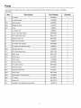
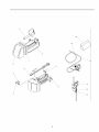
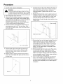
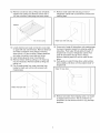
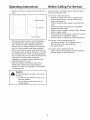
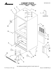
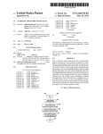
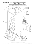
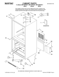
IC7 Bottom
Freezer
Refrigerator Ice
Maker Kit
Installation and
Operating
Instructions
2
Contents
Safety Instructions
Introduction ...............................................................
3
WARNING
Safety Instructions ....................................................
Materials Required ..................................................
Parts .......................................................................
Procedure ...............................................................
3
3
4
6
To avoid electrical shock which can cause
severe personal injury or death, disconnect
power to refrigerator before installing kit.
After installing kit, connect power.
Operating Instructions ...............................................
Before Calling for Service .........................................
Warranty .................................................................
9
9
10
Introduction
Recognize
precaution
this symbol as a safety
Caution
To avoid personal injury or property damage,
observe all safety instructions.
Read entire manual before installing kit. All necessary
tools and materials must be available prior to
installation. Verify all listed parts are included in kit. If
parts are missing, contact source from whom kit was
purchased.
Mechanical experience is required to install kit.
Depending on installer's knowledge and skill,
installation can take from 3 to 6 hours.
If unable to solve a problem during installation,
contact an authorized Amana ®technician. Locate a
Factory Service Center or independent authorized
Amana ®technician by calling 1-800-628-5782 inside
U.S.A. and 1-319-622-5511 outside U.S.A. Service
is at owner's expense.
Caution
To avoid property damage, observe the
following:
• Confirm water pressure to water valve is
at least 20 pounds per square inch.
• Start nuts by hand to avoid cross
threading. Finish tightening nuts using an
adjustable wrench. Do not overtighten.
• Check carefully for water leaks prior to
returning refrigerator to normal location
and 24 hours after connection.
Materials Required
Important
• Before connecting ice maker, contact a plumber to
connect copper tubing to household plumbing in
compliance with local codes and ordinances.
• Amana Refrigeration, Inc. recommends using a
saddle valve. Do not use self-piercing valve. Amana
Refrigeration, Inc. is not responsible for property
damage due to improper installation or water
connection.
1/4" (6 mm) flexible copper tubing*.
*Length of copper tubing must reach from water supply
connection plus an additional 8' (2 m) for service loop
behind refrigerator. Tubing should be soft instead of
rigid and ends should be free of burrs.
Parts
Use listed part numbers only when ordering replacement parts. Part numbers are not used in installation
instructions.
Item
Description
Part Number
Quantity
1
Ice maker
D7824702
1
2
Ice maker cover
10519801
1
N/S
Warning label
A3036901
1
N/S
Diagnostic label
10834701
1
N/S
Label
10549601
2
3
Ice maker arm
10884401
1
4
Lower mounting bracket
B8391802
1
5
1/2" sheet metal screw
M0211017
1
6
Stainless steel clip
B5720301
1
7
Water fill tube elbow
10463201
1
8
Ice maker wire harness
D7813004
1
9
Ice maker wire harness clamp
10526701
1
N/S
Thermal fuse clip
10319801
1
10
5/8" sheet metal screw
M0211018
3
N/S
Button plug
M0311301
2
N/S
Oblong plug
A3124301
1
11
Water valve
10524606
1
12
Nut and sleeve
M0753001
1
13
1/4" plastic tubing
B5705325
1
14
Anti-kink spring
A1055101
1
N/S
Stainless steel insert
A3223101
1
N/S
Hose clamp
M0114003
1
N/S
Compression
10244904
1
N/S
"P" clamp
M0102301
1
15
Plastic clip
M0104101
1
16
Installation and operating instructions
10527010
1
nut and sleeve
4
16
15
\
3
4
\
6
!
11
14
_12
Procedure
7. Connect wires to water valve. Place water valve on
1. Turn off water supply to refrigerator.
mounting bracket. Insert screws into top 2 holes in
water valve cover plate and lower 2 holes in
mounting bracket. Tighten screws with a 1/4" hex
nut driver.
Caution
To avoid property damage, protect soft vinyl
or other flooring with cardboard, rugs, or other
protective material when moving refrigerator.
8. Replace fiberboard back cover by placing cover on
refrigerator cabinet. Insert and tighten screws with a
1/4" hex nut driver. Confirm elbow on water valve
2. Move refrigerator away from wall.
3. Seal open end of copper tubing with masking tape
to keep inside of tubing clean. Route copper tubing
up to refrigerator through floor or interior wall behind
refrigerator providing 3/8" (10 mm) holes as
required. Copper tubing route must be above 35°F
(1°C) to prevent water line from freezing.
4. Remove a section of the fiberboard back cover by
removing screws with a 1/4" hex nut driver. Fold
cover back to expose water valve mounting bracket
and cover plate.
protrudes through hole in back cover. Confirm
plastic tubing is routed through cutout section on top
of back cover.
Plastic tubing
.......
::::::::.
.....
Water valve elbow
9. Remove tape from end of copper tubing. Put end of
copper tubing into sink or bucket. Slightly turn on
water supply to refrigerator. Water will be under
considerable pressure. Allow water to run through
copper tubing for 1 minute to flush out copper
tubing. Turn off water supply to refrigerator when
flushing is complete.
10. Remove plastic cap from water valve. Place brass
nut and brass sleeve on copper tubing. Insert
copper tubing into water valve inlet port. Connect
brass nut on copper tubing to water valve inlet port
with an adjustable wrench. Confirm copper tubing is
secure by pulling on copper tubing.
11. Turn on water supply to refrigerator and check for
leaks. Turn off water supply to refrigerator and
correct any leaks. Repeat this process until no leaks
are found, then completely turn on water supply to
refrigerator.
S,J'"
•9 ¸ :_ _
jz ....
1/4" (6 mm) scr
)ws
5. Remove water valve cover plate by removing 2
screws with a 1/4" hex nut driver. Discard water
valve cover plate. Save screws. Use screws to
install water valve.
6. Remove wires by pushing wire tie through hole in
water valve cover plate with pliers. Do not cut wire
tie near wires.
Wire tie
6
12.Removeiceservicerackby liftingrackoffplastic
washersthenpullingout.Removescrewswitha
1/4"hexnutdriver.Insertplugsintoscrewholes.
17. Remove water tube inlet hole plug on rear of
refrigerator cabinet with a screwdriver covered with
masking tape.
/
f
Washer
\
}
1/4" (6 mm)
13. Locate electrical and water connection cover plate
on upper left rear wall of freezer. Remove electrical
and water connection cover plate by removing
screw with a 1/4" hex nut driver. Discard electrical
and water connection cover plate and screw.
14. Insert oblong plug into cover mounting slot.
15. Remove freezer shelf by pulling out. A sharp tug
may be necessary. Remove basket by lifting and
pulling out.
16. Cut out sealing tape from water inlet tube hole,
located on back wall, with a knife covered with
masking tape.
Water tube inlet hole plug
............................
18. Cover end of water fill tube elbow with masking tape
to prevent insulation beads from entering water fill
tube elbow. Push water fill tube elbow through "U"
shaped hole on back of refrigerator cabinet. Pull
water fill tube elbow through hole in freezer.
Remove masking tape from end of water fill tube
elbow.
19. Push gently on water fill tube elbow while twisting
elbow slightly until elbow is firmly seated inside "U"
shaped hole.
Water fill tube elbow
...............
Water inlet tube hole--4
20. Remove ice maker from shipping carton. Ice maker
is shipped with arm down. This is correct for ice
production. Do not force arm down or up, past stop
positions.
21. Slidestainlesssteelclipoverwallof icemaker
watercup.
Stainless steel clip
22. Remove 3 button plugs from left freezer wall with a
knife covered with masking tape. Discard plugs.
23. Start 5/8" (15 mm) sheet metal screw in top front
hole on left wall with a 1/4" hex nut driver. Leave
head out approximately 3/8" (9 mm).
24. Hold ice maker in position. Ice maker can only be
installed one way. Do not drill additional holes.Insert
wire harness plug into receptacle on rear wall until
locking fingers on top and bottom of plug snaps into
place. Slide ice maker hanger over sheet metal
screw. Ease ice maker water cup toward end of
water fill tube elbow. Water fill tube elbow fits under
stainless steel clip. Water fill tube elbow must not
be kinked. Water fill tube elbow should extend
approximately 3/8" (9 mm) into ice maker water cup
and must be secured under stainless steel clip.
25. Insert and tighten remaining 5/8" (15 mm) sheet
metal screws with a 1/4" hex nut driver.
26. Replace freezer shelf by sliding in until back locks in
place. Replace wire basket by sliding in. Position ice
storage bucket on wire section of freezer shelf under
ice maker. Confirm bucket is in the proper position.
27. Check for leaks at household water connection and
water valve. Correct any leaks.
28. Create service loop using extreme care to avoid
kinks. Secure copper tubing to refrigerator
cabinet using "P" clamp.
29. Move refrigerator in place and level if necessary.
8
Operating Instructions
Before Calling For Service
Confirm ice bucket is in place and ice maker arm is
down.
.....
===
.
Give ice maker 1 overnight period to make ice before
assuming a difficulty exists.
If ice maker is not producing ice
• Confirm ice maker arm is down. Ice bucket and
:............................
I
I
'
i
"-
.....
'
Lo ;ked position
X,IX
Up position
slide out shelf must be in proper position for ice
maker to produce ice.
• Confirm household water supply is reaching water
valve.
•
•
Confirm ice maker wiring harness is completely
inserted into proper holes.
Check for kinks in copper or plastic tubing. Remove
kinks or replace tubing.
Check electrical connections to water valve coil and
•
connector block on refrigerator cabinet.
Confirm freezer is operating at proper temperature.
•
',' Down osition
• After freezer section reaches normal temperature,
ice maker fills with water and begins operating.
Allow 24-48 hours after installation before first
harvest of ice. Ice maker produces 7 to 9 harvests
of ice in a 24-hour period under ideal conditions.
• After ice is formed, ice maker drops ice cubes into
ice storage bucket. During ice production, ice maker
arm raises and lowers. When ice storage bucket is
full, ice maker arm turns ice maker off. Discard first
3 harvests of ice after initially connecting
refrigerator to household water supply and after
extended periods of non-use.
• Stop ice production by lifting ice maker arm. A
definite click is heard when proper position is
reached. Ice maker arm will remain in that position
until pushed down.
Caution
To avoid damage to ice maker, observe the
following:
• Do not force ice maker arm down or up,
past stop position.
• Do not place or store anything in ice
storage bucket.
If ice maker is not producing enough ice
• Ice maker produces 7 to 9 harvests of ice in a
24-hour period under ideal conditions.
• See above section.
If ice maker makes unfamiliar sounds.
• These may be normal. Refer to "Normal Operating
Sounds" section in Owner's Manual.
Warranty
Ice Maker
Full One Year Warranty
First Year
Amana Refrigeration, Inc. will repair or replace, free of charge, any part which is defective due to
workmanship or materials.
Warranty Limitations
• Begins at date of original purchase.
• Applies to product used within the United States
or in Canada if product has Canadian Standards
Association listing when shipped from the
factory.
• Service must be performed by an authorized
Amana ®technician.
Warranty Is Void If
• Product is used on a commercial, rental or
leased basis.
• Product has defect or damage due to an
accident, fire, flood, connection to an improper
electrical or water supply, lightning, product
alteration, shipping and handling, or other
conditions beyond the control of Amana
Refrigeration, Inc.
• Product is improperly installed or used.
Owner's Responsibilities
• Provide proof of purchase (sales receipt).
• Provide normal care and maintenance. Replace
owner replaceable items where directions appear
in Installation and Operating Instructions.
• Make product reasonably accessible for service.
• Pay for premium service costs for service
outside technician's normal business hours.
• Pay for service calls related to product
installation or usage.
In no event shall Amana Refrigeration, Inc. be
liable for incidental or consequential damages*
*This warranty gives you specific legal rights and
may have others which vary from state to state.
example, some states do not allow the exclusion
limitation of incidental or consequential damages
this exclusion may not apply to you.
10
you
For
or
so
11
Part No. 10527010
Printed in U.S.A.
sna
A Ra_/l'h_.NmCompany
_h1996 Amana Refrigeration, Inc.
Amana, Iowa 52204