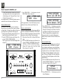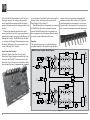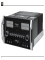
1
McIntosh Laboratory, Inc.
2 Chambers Street Binghamton, New York
MA8000
Integrated Amplifier
Owner’s Manual
13903-2699 Phone: 607-723-3512
www.mcintoshlabs.com
The lightning flash with arrowhead, within an equilateral
triangle, is intended to alert the user to the presence of
uninsulated “dangerous voltage” within the product’s enclosure that may be of sufficient magnitude to constitute
a risk of electric shock to persons.
WARNING - TO REDUCE RISK
OF FIRE OR ELECTRICAL
SHOCK, DO NOT EXPOSE
THIS EQUIPMENT TO RAIN OR
MOISTURE.
IMPORTANT SAFETY
INSTRUCTIONS!
PLEASE READ THEM BEFORE
OPERATING THIS EQUIPMENT.
1. Read these instructions.
2. Keep these instructions.
3. Heed all warnings.
4. Follow all instructions.
5. Do not use this apparatus near water.
6. Clean only with a dry cloth.
7. Do not block any ventilation openings. Install
in accordance with the manufacturer’s instructions.
8. Do not install near any heat sources such as
radiators, heat registers, stoves, or other apparatus (including amplifiers) that produce heat.
9. Do not defeat the safety purpose of the polarized or grounding-type plug. A polarized plug
has two blades with one wider than the other.
A grounding type plug has two blades and a
2
The exclamation point within an equilateral triangle is
intended to alert the user to the presence of important
operating and maintenance (servicing) instructions in the
literature accompanying the appliance.
NO USER-SERVICEABLE PARTS
INSIDE. REFER SERVICING TO
QUALIFIED PERSONNEL.
third grounding prong. The wide blade or the
third prong are provided for your safety. If
the provided plug does not fit into your outlet,
consult an electrician for replacement of the
obsolete outlet.
10. Protect the power cord from being walked on
or pinched particularly at plugs, convenience
receptacles, and the point where they exit
from the apparatus.
11. Only use attachments/accessories specified by
the manufacturer.
12. Use only with the cart, stand, tripod, bracket,
or table specified by the manufacturer, or sold with the apparatus. When a cart is used, use
caution when moving the cart/
apparatus combination to avoid
injury from tip-over.
13. Unplug this apparatus during lightning storms
or when unused for long periods of time.
14. Refer all servicing to qualified service personnel. Servicing is required when the apparatus
has been damaged in any way, such as power-
To prevent the risk of electric
shock, do not remove cover or
back. No user-serviceable parts
inside.
supply cord or plug is damaged, liquid has
been spilled or objects have fallen into the
apparatus, the apparatus has been exposed to
rain or moisture, does not operate normally, or
has been dropped.
15. Do not expose this equipment to dripping or
splashing and ensure that no objects filled
with liquids, such as vases, are placed on the
equipment.
16. To completely disconnect this equipment from
the a.c. mains, disconnect the power supply
cord plug from the a.c. receptacle.
17. The mains plug of the power supply cord shall
remain readily operable.
18. Do not expose batteries to excessive heat such
as sunshine, fire or the like.
19. Connect mains power supply cord only to a
mains socket outlet with a protective earthing
connection.
Thank You
Customer Service
Your decision to own this McIntosh MA8000 Integrated Amplifier ranks you at the very top among
discriminating music listeners. You now have the best.
The McIntosh dedication to precision performance
assures many years of musical enjoyment.
Please take a short time to read the information in
this manual. We want you to be as familiar as possible with all the features and functions of your new
McIntosh.
If it is determined that your McIntosh product is in
need of repair, you can return it to your Dealer. You
can also return it to the McIntosh Laboratory Service
Department. For assistance on factory repair return
procedure, contact the McIntosh Service Department
at:
Please Take A Moment
The serial number, purchase date and McIntosh Dealer
name are important to you for possible insurance
claim or future service. The spaces below have been
provided for you to record that information:
Serial Number:________________________________
Purchase Date:________________________________
Dealer Name:_________________________________
Technical Assistance
If at any time you have questions about your McIntosh
product, contact your McIntosh Dealer who is familiar
with your McIntosh equipment and any other brands
that may be part of your system. If you or your Dealer
wish additional help concerning a suspected problem,
you can receive technical assistance for all McIntosh
products at:
McIntosh Laboratory, Inc.
2 Chambers Street
Binghamton, New York 13903
Phone: 607-723-3512
Fax: 607-724-0549
Copyright 2013 © by McIntosh Laboratory, Inc.
McIntosh Laboratory, Inc.
2 Chambers Street
Binghamton, New York 13903
Phone: 607-723-3515
Fax: 607-723-1917
Table of Contents
Safety Instructions.............................................................2-3
Thank You and Please Take a Moment................................3
Technical Assistance and Customer Service........................ 3
Table of Contents..................................................................3
General Information.............................................................4
Connector and Cable Information........................................4
Introduction.......................................................................... 5
Performance Features...........................................................5
Dimensions........................................................................... 6
Installation............................................................................7
Connections:
Rear Panel Connections........................................................ 8
(Separate Sheet)............................................................Mc1A
Connecting Components...................................................... 9
Connection Diagrams (Separate Sheet)..................Mc2A/2B
Passthru Connections......................................................... 10
Connecting for Bi-Amplification....................................... 11
Connecting Loudspeakers............................................. 12-13
Remote Control and Front Panel:
Remote Control Push-buttons............................................ 14
How to use the Remote Control.......................................... 15
Front Panel Displays, Controls,
Push-buttons and Jack........................................................ 16
Setup Mode:
How to Operate the Setup Mode........................................ 17
Default Settings........................................................... 17
Firmware Version........................................................ 18
Source Input Reassigment........................................... 18
Source Input Renaming............................................... 19
Passthru....................................................................... 20
Power Control Triggers 1 and 2................................... 20
Comm Port Baud Rate................................................. 21
Remote Control Codes................................................ 22
Power Mode................................................................. 22
Operation:
How to Operate the MA8000............................................. 24
Power On/Off.............................................................. 24
Source Selection.......................................................... 24
Volume Control........................................................... 24
Trim Functions:
Balance............................................................... 24
Equalizer Mode.................................................. 25
Trim Level.......................................................... 25
Mono/Stereo Mode and Phono Adjustments..... 26
Display Brightness............................................. 26
Digital Audio Display........................................ 27
Meter Backlight................................................. 27
Equalizer Bypass, Trim, Mute.................................... 27
Headphone Jack........................................................... 27
Power Output Meters................................................... 28
Power Guard and How to Make a Recording.............. 28
Using a Separate Power Amplifier.............................. 28
Using Output 2............................................................ 28
Passthru and Equalizer Controls................................. 29
Optical and Coaxial Digital Inputs............................. 30
USB Input Operation with a Computer....................... 30
Reset of Microprocessors............................................ 30
Resetting the MA8000 to default settings.................. 30
Technical Description........................................... 32-37
Photos....................................................................38-40
Specifications........................................................ 41-42
Packing Instructions.................................................. 43
3
General Information, Connector and Cable Information
General Information
1. For additional connection information, refer to the
owner’s manual(s) for any component(s) connected
to the MA8000.
2. Apply AC Power to the MA8000 and other McIntosh Component(s) only after all the system components are connected together. Failure to do so may
cause a malfunction of system operations as the
Microprocessor’s Circuitry inside the components
is active when AC Power is applied.
3. The MA8000 includes an Auto Off Power Save
Feature and the default setting is enabled. For
additional information including how to disable it,
refer to page 22.
4. When Power Amplifier Protection Circuitry of
the MA8000 has activated, the Front Panel Power
Guard LEDs are illuminated continuously and the
sound will be muted.
5. When the Power Transformer has overheated due
to improper ventilation and/or high ambient operating temperature, AC Power is removed from the
MA8000. Normal operation will resume when the
operating temperature is in a safe range again.
6. For the best performance and safety, it is important
to always match the impedance of the Loudspeaker
to the Power Amplifier connections. Refer to pages
11 thru 13.
Note: The impedance of a Loudspeaker actually varies as the Loudspeaker reproduces different
frequencies. As a result, the nominal impedance
rating of the Loudspeaker (usually measured at
a midrange frequency) might not always agree
with the impedance of the Loudspeaker at low
frequencies where the greatest amount of power
is required. Contact the Loudspeaker Manufacturer for additional information about the actual
impedance of the Loudspeaker before connecting
it to the McIntosh MA8000.
4
7. The MA8000 Remote Control is capable of operating other components. For additional information
go to www.mcintoshlabs.com.
8. The IR Input, with a 1/8inch mini phone jack, is
configured for non-McIntosh IR sensors such as
a Xantech Model HL85BK Kit. Use a Connection
Block such as a Xantech Model ZC21 when two
or more IR sensors need to be connected to the
MA8000. The signal from a connected External
IR Sensor will have priority over the signal from
the Front Panel IR Sensor.
9. When discarding the unit, comply with local rules
or regulations. Batteries should never be
thrown away or incinerated but disposed
of in accordance with the local regulations concerning battery disposal.
10. For additional information on the
MA8000 and other McIntosh Products please visit
the McIntosh Web Site at www.mcintoshlabs.com.
Data Port Connectors
The Data Out Ports send Remote
Control Signals to Source Components. A 3.5mm stereo mini phone
plug is used for connection.
Data
Signal
N/C
Data
Ground
IR IN Port Connectors
The IR IN Port also uses a 3.5mm
stereo mini phone plug and allows the
connection of other brand IR Receivers to the MA8000.
IR Data
Control
N/C
Ground
RS232-C Data Port Cable
The RS232 Data Cable is a 3.5mm stereo mini phone
plug to a sub miniature DB 9 connector:
DB9
Connector and Cable Information
XLR Connectors
Below is the Pin configuration for the XLR Balanced
Input and Output Connectors on the MA8000. Refer
to the diagrams for connections:
PIN 1: Shield/Ground
PIN 2: + Output
PIN 3: - Output
PIN 2
PIN 1
PIN 3
the illumination of the Power Output Meters on McIntosh Power Amplifiers. A 3.5mm stereo mini phone
plug is used for connection to the Power Control, Trigger and Passthru Outputs.
PIN 1
PIN 3
PIN 2
Power Control and Trigger Connectors
Main, Trig 1&2
The Power Control Trigger Output
and Pass-Thru
Jacks send and Passthru Input Jack
receives Power On/Off Signals (+12 Power
volt/0 volt) when connected to other Control
Meter
McIntosh Components. An addiIllumination
Control
tional connection is for controlling
Ground
Data In
(DB9-pin2)
Data Out
(DB9-pin3)
Ground
(DB9-pin5)
PIN 1
PIN 6
(male connector)
PIN 5
PIN 9
McIntosh Plug-In Jumper Connector
The MA8000 utilizes a phono style Plug-In Jumper to
connect the Preamplifier Output to the
Power Amplifier Input, one Jumper for
each channel.
Note: The Jumper Connector is available
from the McIntosh Parts Department:
McIntosh Jumper Connector Part No. 11808000
Introduction and Performance Features
Introduction
Now you can take advantage of traditional McIntosh
standards of excellence in the MA8000 Integrated
Amplifier. The Power Amplifier section of the
MA8000, with a power output of 300 watts per channel, will drive a pair of quality Loudspeakers to a high
level of performance.
The flexible Preamplifier section provides connections for various input sources and may also be used to
drive an external Power Amplifier(s).
The MA8000 reproduction is sonically transparent
and absolutely accurate. The McIntosh Sound is “The
Sound of the Music Itself.”
Performance Features
• Power Output with Patented Autoformer
The MA8000 consists of a 300 watts per channel stereo Power Amplifier with less than 0.005% distortion.
The McIntosh designed and manufactured Autoformer
allows connection of 2, 4 or 8 ohm Loudspeakers. The
Power Amplifier uses ThermalTrak1 Output Transistors for lower distortion and cool operation.
• Power Guard
The patented McIntosh Power Guard circuit prevents
amplifier clipping and protects your valuable Loudspeakers.
• Sentry Monitor and Thermal Protection
McIntosh Sentry Monitor power output stage protection circuits ensure the MA8000 will have a long and
trouble free operating life. Built-in Thermal Protection
Circuits guard against overheating.
• Electronic Switching and Balanced Connections
The Preamplifier uses Logic Circuits controlling
1
ThermalTrak™ and ON Semiconductor are trademarks of Semiconductor Components Industries, LLC
Electromagnetic Switches on all inputs and operating
functions for reliable, noiseless, distortion free switching. There are Balanced Inputs for connection of a
source components.
• PassThru Mode
The Automatic PassThru Mode allows the MA8000
to become part of a Multichannel Sound System for
DVD-Audio, SACD and Home Theater Movies.
• Digital Audio Inputs
The MA8000 has Coaxial, Optical and USB Digital Inputs to decode PCM Signals from an external
source. The MA8000 Up Samples the Digital Signal
to 192kHz with 32 Bit resolution before the Digital to
Analog process begins.
• Power Control and Remote Control
The Power Control Output connection provides convenient Turn-On/Off of McIntosh Source Components.
The Data Ports together with the supplied Remote
Control provide control of McIntosh Source Components connected to the MA8000.
• Moving Coil and Moving Magnet Phono Inputs
The MA8000 contains two precision Phono Preamplifier Circuits. One for low output Moving Coil Phono
Cartridges with selectable resistance loading, the
other is for Moving Magnet Cartridges with selectable
capacitive loading. They use the latest designs for the
lowest possible noise and distortion. The RIAA Correction Circuitry utilizes close tolerance resistors and
capacitors for an extremely flat frequency response.
• Special Power Supply
The large Power Transformer, multiple filter capacitors with 140 Joules of Energy Storage and regulated
Power Supply ensures stable noise free operation even
though the power line varies.
• Eight Band Equalizer
The Equalizer Controls provide 12dB of boost or cut
at center frequencies of 25, 50, 100, 200, 400, 1,000,
2,500 and 10,000Hz. There is also an Equalizer Bypass Mode to remove the Equalizer from the Signal
Path of any selected input.
• Multifunction Fluorescent Display
The Front Panel Display indicates source selection,
volume levels and setup functions.
• Illuminated Power Meters
The Illuminated Power Output Watt Meters on the
MA8000 are peak responding, and indicate the power
output of the amplifier.
• McIntosh Custom Binding Posts
McIntosh Patented gold plated output terminals deliver
high current output. They accept large diameter wire
and spade lugs. Banana plugs may also be used only in
the United States and Canada.
• Fiber Optic Solid State Front Panel Illumination
The even Illumination of the Front Panel is accomplished by the combination of custom designed Fiber
Optic Light Diffusers and extra long life Light Emitting Diodes (LEDs).
• Glass Front Panel and Super Mirror Chassis
Finish
The famous McIntosh Illuminated Glass Front Panel
and the Stainless Steel Chassis with Super Mirror Finish ensures the pristine beauty of the MA8000 will be
retained for many years.
5
Dimensions
Dimensions
The following dimensions can assist in determining
the best location for your MA8000. There is additional
information on the next page pertaining to installing
the MA8000 into cabinets.
Front View of the MA8000
17-1/2"
44.5cm
8-13/16"
22.4cm
Side View of the MA8000
9-7/16"
24.0cm
19-3/4"
2-1/4"
5.7cm
50.2cm
16-7/16"
41.8cm
8-1/4"
21.0cm
3/16"
0.5cm
Rear View of the MA8000
16-13/16"
42.7cm
7/8"
2.2cm
12-3/4"
32.4cm
7-15/16"
7.9cm
11-1/2"
29.2cm
6
1-1/4"
3.2cm
Installation
Installation
The MA8000 can be placed upright on a table or
shelf, standing on its four feet. It also can be custom
installed in a piece of furniture or cabinet of your
choice. The four feet may be removed from the bottom
of the MA8000 when it is custom installed as outlined below. The four feet together with the mounting
screws should be retained for possible future use if the
MA8000 is removed from the custom installation and
used free standing. The required panel cutout, ventilation cutout and unit dimensions are shown.
Always provide adequate ventilation for your
MA8000. Cool operation ensures the longest possible
operating life for any electronic instrument. Do not
install the MA8000 directly above a heat generating component such as a high powered amplifier. If
all the components are installed in a single cabinet, a
quiet running ventilation fan can be a definite asset in
maintaining all the system components at the coolest
possible operating temperature.
A custom cabinet installation should provide the
following minimum spacing dimensions for cool
operation.
Allow at least 6 inches (15.24cm) above the top, 2
inches (5.08cm) below the bottom and 2 inches (5.1cm)
on each side of the Integrated Amplifier, so that
airflow is not obstructed. Allow 20 inches (50.8cm)
depth behind the front panel. Allow 2-1/2 inch (6.4cm)
in front of the mounting panel for knob and handle
clearance. Be sure to cut out a ventilation hole in the
mounting shelf according to the dimensions in the
drawing.
17-1/16"
43.3cm
MA8000 Front Panel
Custom Cabinet Cutout
8-5/16"
21.1cm
Cutout Opening for Custom Mounting
6"
Cabinet
Front
Panel
15.2cm
Opening
for Ventilation
MA8000 Side View
in Custom Cabinet
Cutout Opening for Ventilation
Support
Shelf
4-5/8"
11.8cm
MA8000 Bottom View
in Custom Cabinet
Note: Center the cutout Horizontally
on the unit. For purposes of
clarity, the above illustration
is not drawn to scale.
9-1/2"
24.1cm
Cutout
Opening
for
Ventilation
16"
40.6cm
Chassis
Spacers
11-1/2"
29.2cm
10"
25.4cm
7
MA8000 Rear Panel Connections
Rear Panel Connections
The identification of Rear Panel Connections for the
MA8000 Integrated Amplifier is located on a separate
folded sheet contained in the Owner’s Manual Packet.
Refer to separate sheet “Mc1A” for the Rear Panel
Connections.
MA8000 Rear Panel Connections
8
Connecting Components
Connecting Components
The MA8000 has the ability to automatically switch
power On/Off to McIntosh Source Components via
the Power Control (Trigger) connections. The Data
Port Connections allow for the remote operation of
basic functions using the MA8000 Remote Control.
With an external sensor connected to the MA8000, remote control operation of the system is possible from
another room and/or when the MA8000 is located in a
cabinet with the doors closed.
The connection instructions below, together with
the MA8000 Input and Output Connection Diagrams
located on the separate folded sheet “Mc2A/2B”, are
an example of a typical audio system. Your system
may vary from this, however the actual components
would be connected in a similar manner. For additional information refer to “Connector and Cable Information” on page 4.
Note: Source components may be connected to the
MA8000 Balanced Inputs or Digital Inputs instead of Unbalanced Inputs. Refer to Setup “Reassigning Inputs” to activate them on page 18.
Power Control Connections:
1. Connect a Control Cable from the MA8000 PWR
CTRL (Power Control) MAIN Jack to the Power
Control In on the Turntable.
2. Connect a Control Cable from the McIntosh Turntable Power Control Out Jack to the Audio/Video
Player Power Control In Jack.
3. Connect a Control Cable from the Audio/Video
Player Power Control Out Jack to the AM/FM
Tuner Power Control In Jack.
4. Connect a Control Cable from the AM/FM Tuner
Power Control Out Jack to the SACD/CD Player
Power Control In Jack.
5. Optionally connect a Control Cable from the
MA8000 PWR CTRL (Power Control) TRIG
(Trigger) 2 Jack to the Power Amplifier (Secondary Room) Power Control In Jack.
Note: The default setting for the TRIG 2 Jack is
“MAIN”. Refer to Setup “Power Control Triggers 1 and 2” on page 20 to change TRIG 2 setting to “OUTPUT 2”.
6. Connect any additional McIntosh Components in
a similar manner, as outlined in steps 1 thru 4.
Data Control Connections:
7. Connect a Control Cable from the MA8000 CD
DATA PORT Jack to the SACD/CD Player Data In
Jack.
8. Connect a Control Cable from the MA8000
TUNER DATA PORT Jack to the AM/FM Tuner
Data In Jack.
9. Connect a Control Cable from the MA8000 DVD
DATA PORT Jack to the Audio/Video Player Data
In Jack.
10. Connect any additional McIntosh Components in
a similar manner, as outlined in steps 7 thru 9.
Sensor Connection:
11. Optionally, connect the cable with stereo mini
plug coming from the compatible External Sensor
to the EXT CTRL (External Control) IR IN Jack
on the MA8000. Refer to page 4 “General Information, note 8” for additional information.
Audio Connections:
12. Connect Balanced Cables from the MA8000 BAL
(Balanced) INPUT 1 L & R Connectors to the
SACD/CD Player Fixed Audio Output Balanced
Connectors.
13. Connect Audio Cables from the MA8000 TUNER
INPUT Jacks to the AM/FM Tuner Output Jacks.
14. Connect Audio Cables from the MA8000 DVD
INPUT Jacks to the Audio/Video Player Output
Jacks.
15. Connect the Audio Cables coming from the Turntable to the MA8000 PHONO INPUT MC (for a
Moving Coil Cartridge) or PHONO INPUT MM
(for a Moving Magnet Cartridge) Jacks.
16. Optionally, connect Audio Cables from the
MA8000 OUTPUT 2 (Balanced) Jacks to the
Power Amplifier (Secondary) Input Jacks.
17. Connect any additional Components in a similar
manner, as outlined in steps 11 thru 14.
Optional Digital Audio Connections:
18. Connect a Coaxial Cable from the MA8000 DIG
(Digital) 4 Digital Audio Input Jack to the Digital
Out Coaxial Jack on the Audio/Video Player.
Note: Source components may be connected to the
MA8000 Digital Inputs instead of Analog Inputs.
Refer to Setup “Reassigning Inputs” to activate
them on page 18.
19. Connect an Optical Cable from the MA8000
DIG (Digital) 1 Digital Audio Input connector to
the Digital Audio Out Optical Connector on the
SACD/CD Player.
Optional USB Connection:
20. Connect a USB cable with (type A to type B) connectors from the MA8000 USB D/A Digital Audio
Input to an available USB connector.
Ground Connections:
21. Connect the Ground Cable coming from the Turntable to the MA8000 GND Binding Post.
Notes: 1. If the MA8000 is part of a Home Theater
System, proceed to “PassThru” connection on
page 10.
2. When the MA8000 will used together with a
separate Power Amplifier for Bi-Amplification
of a Loudspeaker System, proceed to page 11.
9
Passthru Connections
Passthru Connections
The MA8000 can be part of a Multichannel Sound
System for SACD, DVD-Audio and Home Theater.
The Right and Left Front Channels from an Audio/
Video Control Center can “Passthru” the MA8000. In
the following example the SRVR Input will become
the “Passthru” input:
1. Connect Audio Cables from the A/V Control
Center Front Left and Right Channel Outputs to
the MA8000 SRVR Input Left and Right Jacks.
2. Connect a Control Cable from the A/V Control
Center ZA (Zone A) PC (Power Control) Output
to the MA8000 PWR CTRL (Power Control)
PASSTHRU Input Jack.
Note: Refer to Setup “Passthru” on page 20 to assign
the SRVR Input as the “Passthru” Input.
3. Proceed to “Connecting Loudspeaker” on
Page 12.
10
A/V Control Center
Connecting for Bi-Amplification
Connecting for Bi-Amplification
The MA8000’s Power Amplifier, together with an
additional separate Power Amplifier, may be used to
Bi-Amplify a Loudspeaker System. In the illustration
on this page the Power Amplifier of the MA8000 is
connected to the Midrange/High Frequency Section
of the Loudspeaker. The additional separate Power
Amplifier is connected to the Low Frequency Section
of the Loudspeaker System.
Warning: The Loudspeaker System used for
Bi-Amplification must have the
jumpers removed from between the
MID/HIGH and LOW Frequency
Sections of the Loudspeaker System.
Failure to remove them could result
in damage to the MA8000 and/or the
separate Power Amplifier.
MA8000 Connections:
1. Remove the “McIntosh Jumpers” from between
the OUTPUT 1 Jacks and the PWR AMP In Jacks
located on the Rear Panel of the MA8000.
Note: Place the “McIntosh Jumper” in a safe place
for possible future use.
2. Using a pair of shielded RCA Type Audio “Y”
Adapters connect the OUTPUT 1 Jacks to the
PWR AMP In Jacks, for both Left and Right
Channels.
3. Connect the remaining unconnected part of the
“Y” Adapters to the separate Power Amplifier.
4. Referring to the Loudspeaker Connection Instructions on page 12, and in the Owner’s Manual supplied with the Power Amplifier and Loudspeaker,
connect the MA8000 Output Terminals to the
Loudspeaker MID/HIGH Input Terminals.
Left Channel
Loudspeaker
“Y” adapter Cable
Power Amplifier
-
+
Note: The Loudspeaker Connection illustrations
on this page are for the Left Channel. Connect the Right Channel Loudspeaker in the
same manner.
11
Output Terminals
When connecting the Loudspeaker Hookup Cables to
the MA8000 Amplifier Output Terminals please follow the steps below:
1. Rotate the top of the Output Terminal Post counterclockwise until an opening
appears. Refer to figures A and
B.
2. Insert the Loudspeaker hookup
cable into the Output Terminal
Opening
Post opening or the cable spade
Figure B
Figure A
lug around the center post of
the Output Terminal. Refer to
figure C.
3. Rotate the top of the Output
Terminal Post clockwise until it
is finger tight. Refer to figure D.
4. Place the supplied McIntosh
Figure C Figure D
Wrench over the top of the Output Terminal and rotate it one
quarter of a turn (90° ) to secure
the Loudspeaker Cable ConnecFigure E
tion. Do not over tighten. Refer
to figure E.
How to Connect Loudspeakers
Caution: Do not connect the AC Power Cord to the
MA8000 Rear Panel until after the Loudspeaker
Connections are made. Failure to observe this
could result in Electric Shock.
The connection instructions below, together with the
MA8000 Connection Diagram located on the separate
folded sheet “Mc2B”, is an example of a typical audio
system. Your system may vary from this, however the
actual components would be connected in a similar
manner. For additional information refer to “Connector and Cable Information” on page 4.
12
The McIntosh MA8000 Power Amplifier Circuitry
is designed for Loudspeakers with an impedance of
2 ohms, 4 ohms or 8 ohms. Connect a single Loudspeaker only to the Right and Left Output Terminals.
When connecting Loudspeakers to the MA8000
it is very important to use cables of adequate size, so
there is little to no power loss in the cables. The size is
specified in Gauge Numbers or AWG (American Wire
Gauge). The smaller the Gauge number, the larger the
wire size:
Loudspeaker Cable Distance vs Wire Gauge Guide
Loudspeaker
Impedance
25 feet
(7.62 meters)
or less
50 feet
(15.24 meters)
or less
100 feet
(30.48 meters)
or less
2 Ohms
12AWG
10AWG
8AWG
4 Ohms
14AWG
12AWG
10AWG
8 Ohms
16AWG
14AWG
12AWG
1. Prepare the Loudspeaker Hookup Cable for attachment to the MA8000 Power Amplifier:
Bare wire cable ends:
Carefully remove sufficient insulation from the
cable ends, refer to figures F, G & H. If the cable
is stranded, carefully twist the strands together
as tightly as possible.
Figure F
Figure G
Figure H
Notes: 1. If desired, the twisted ends can be tinned
with solder to keep the strands together.
2. The prepared bare wire cable ends may be
inserted into spade lug connectors.
3. Banana plugs are for use in the United
States and Canada only.
Banana Plugs are for use in the United States and
Canada only:
2. Attach the previously prepared bare wire cable ends
into the banana plugs and secure
the connections. Refer to figure I.
3. Rotate the Output Terminal Post
clockwise until it is finger tight.
Figure I
Refer to figure J. Then using the
McIntosh Wrench, rotate the top of
the Output Terminal one quarter of
a turn (90° ). Do not over tighten.
Refer to figure E.
4. Referring to figure K, connect the
Loudspeaker hookup cables with
Figure J
banana plugs into the hole at the
top of the terminal to
the MA8000 Negative
Output Terminal and
Positive Output Terminal indentified as 2Ω
(ohms), 4Ω (ohms) or
Figure K
8Ω (ohms) connection
to match the impedance of the Loudspeaker, being
careful to observe the correct polarities.
Note: The illustration located on the separate
folded sheet “Mc2B” is for connection to an
8Ω (ohms) Loudspeaker.
If the Loudspeaker’s impedance is in-between
the available connections, use the nearest lower
impedance connection. Refer to “General Information” Note 6 on page 4 for additional information.
WARNING: Loudspeaker terminals are hazardous live and present a risk of electric
shock. For additional instruction on
making Loudspeaker Connections contact your McIntosh Dealer or McIntosh Technical Support.
Connecting Loudspeakers
5. Connect the MA8000 power cord to an active AC
outlet.
Spade Lug or Wire Connections:
6. Connect the Loudspeaker hookup cables to the
MA8000 Negative Output Terminal and Positive Output Terminal indentified as 2Ω (ohms),
4Ω (ohms) or 8Ω (ohms) connection to match the
impedance of the Loudspeaker, being careful to
observe the correct polarities. Insert the spade
lug connector or prepared section of the cable end
into the terminal side access hole, and tighten the
terminal cap until the cable is firmly clamped into
the terminals so the lugs or wire cannot slip out.
Refer to figures L and M.
Note: The illustration located on the separate folded
sheet “Mc2B” is for connection to an 8Ω
(ohms) Loudspeaker.
Figure L
Figure M
If the Loudspeaker’s impedance is in-between the
available connections, use the nearest lower impedance connection. Refer to “General Information” Note 6 on page 4 for additional information.
WARNING: Loudspeaker terminals are hazardous live and present a risk of electric
shock. For additional instruction on
making Loudspeaker Connections contact your McIntosh Dealer or McIntosh Technical Support.
7. Connect the MA8000 power cord to an active AC
outlet.
13
Remote Control Push-Buttons
LED illuminates during the time a remote command is sent to the MA8000
Switches the Trigger 1 and/or 2
Power Control Jack(s) On/Off, refer
to “Setup, Power Control TRIG 1
and TRIG 2” on page 20 for additional information
Selects a Disc Player, Music Server or
Recorder Function. Seek Stations Up
or Down the AM/FM Dial. Select and/
or enter AM/FM Station Presets and
performs various functions on a variety of McIntosh Components
Displays On Screen Functions on the
McIntosh Music Server and a variety
of other McIntosh Components
Adjusts the volume level up or down
Activates the TRIM
Stereo/Mono Mode
Mutes the audio
Selects AM Tuner Operating
Functions and Disc Selection on
certain McIntosh Disc Players
Selects Functions as a “shift” key
when used with the AM or FM
push-buttons to select Output 1
or 2
Scrolls through the available
MA8000 Inputs
Press to Power the MA8000 ON
Press to Power the MA8000 OFF
Press to change broadcast bands on
an external McIntosh Tuner connected. Select certain functions on a
variety of McIntosh Components
Selects On Screen Functions on a
variety of McIntosh Components
Press TRIM and then the LEVEL
Push-buttons to select and adjust
various functions
Selects FM Tuner Operating Functions and Track Selection on certain
McIntosh CD Players
Use to select tuner presets, direct access an AM/FM Station Frequency,
disc tracks or any numbered operation
Scrolls through the available
MA8000 Inputs
Selects one of the eight
available Audio Sources
Note: Push-buttons whose function is not identified above are for use with other McIntosh Products.
14
How to use the Remote Control
How to use the Remote Control
The supplied HR072 Remote Control is capable of
directly controlling the functions of contemporary
Source Components connected to the MA8000 via the
Data Ports.
Notes: 1. If at any time the MA8000 seems unresponsive to HR072 Remote Control Commands
press the
Push-button first.
2. For additional information on using the
HR072 Remote Control with the MA8000,
please refer to the “How to Operate” section
of this Owner’s Manual starting on page 24.
Input Source Selection
Press the appropriate Source Push-button to select the
desired program source.
Note: When the MA8000 is Off, pressing one of the
Source Push-buttons will switch the MA8000 On
and it will go to that Input.
Mute
Press the MUTE Push-button to mute the audio in all
outputs except the REC OUTPUT. The word MUTE
will appear on the Front Panel Display. To un-mute the
audio, press the MUTE Push-button again.
Disc, Server and Recorder Functions
Use these push-buttons to operate a DVD Player, CD
Player, CD Changer, Music Server or Recorder.
Numbered Push-buttons
Press Push-buttons 0 through 9 to access tuner station presets, tracks on discs or selections on a Music
Server.
Disc and Track
Use the AM (disc) and FM (track) Push-buttons when
a Disc Player or Music Server is being used.
Tuner Push-buttons
Press the AM or FM Push-button to select the desired
broadcast band. Press and release the Seek Up : the
band or Seek Down 9 the band Push-button to seek
the next available station. Press and hold a Directional
Up p or Down q Push-button to tune continuously
from station to station.
Amplifier Selection
Press the BLUE (Setup) Push-button followed by the
AM (Output 1) or FM (Output 2) Push-button, to control the rear panel Audio OUTPUTS 1, 2 (ON or OFF)
and Power Control TRIG 1 / TRIG 2. These OUTPUTS provide signals to the MA8000 Power Amplifier and/or other accessory component.
Note: Refer to SETUP on page 20 “Power Control
Triggers 1 and 2 to change the default setting of
“MAIN” to “REMOTE”.
Volume
Press the VOLUME Up p or Down q Push-button to
raise or lower the listening volume level.
Note: The Record Signals present at REC OUTPUTS are
not affected by volume changes.
Pause
Press the Pause Push-button to perform various
functions on a variety of McIntosh Components. It
will also pause the playing of a disc or tape player.
Trim
Press the TRIM Push-button until the desired Trim
function (Balance, Trim Level, etc.) appears on the
Front Panel Display, then press the LEVEL Up p or
Down q Push-button to adjust the Trim setting.
Note: Press the TRIM Push-button to recall the last Trim
function selected. For additional information on
the Trim Functions refer to page 24 thru 27.
15
INPUT Control allows the
selection of various sources
for listening and recording.
TRIM allows selection
of various types of audio
settings. It is also used in
the setup mode for various
functions
LED indicates when the Right
Channel Amplifier POWER
GUARD circuit activates
LED indicates when the Left
Channel Amplifier POWER
GUARD circuit activates
Meter indicates the
Left Channel Output
of the amplifier
EQUALIZER Controls increase or decrease the volume levels at the Center Frequencies of 25Hz, 50Hz, 100Hz, 200Hz,
400Hz, 1,000Hz, 2,500Hz and 10,000Hz
Meter indicates the
Right Channel Output
of the amplifier
STANDBY/ON Push-button
with indicator switches
the MA8000 ON or OFF
(Standby) and resets the
microprocessors
Connection for dynamic
type headphones, for
private listening
INFORMATION DISPLAY indicates the
Sources, Volume, other Audio Settings,
Operational Functions and Setup Mode
Settings
OUTPUT 1 and 2 Push-buttons with
indicators, switch Preamplifier Output
(Loudspeakers) 1 and 2 On or Off
16
VOLUME Control allows
adjustment of the listening
level for both channels.
ADJUST is also used in
the setup mode for various
functions
IR Sensor receives
commands from a
Remote Control
EQ BYPASS Push-button
with indicator, when activated
the audio signal bypasses the
Equalizer Controls
MUTE Push-button mutes the
audio from the Loudspeakers
and Headphones
Setup
How to Operate the Setup Mode
Your McIntosh MA8000 has been factory configured
for default operating settings that will allow immediate enjoyment of superb audio without the need for
further adjustments. If you wish to make changes to
the factory default settings, a Setup Feature is provided to customize the operating settings using the
Front Panel Display. Refer to the MA8000 Front Panel
Illustration on the previous page while performing an
introduction into operating the Setup Mode, follow the
steps below.
Note: If the MA8000 is currently On, proceed to
step 2.
1. Press the STANDBY/ON Push-button on the Front
Panel or press the
(Power) Push-button on the
Remote Control to switch On the MA8000. The
MA8000 will go through a brief startup intialization with the Front Panel Display indicating
the last used source and volume setting. This is
followed by the volume setting indication starting
at zero and then increasing to the last used volume
setting. Refer to figure 1.
SOURCE: CD
15%
Figure 1
2. Press and hold the INPUT CONTROL until the
Front Panel Display indicates “MA8000 V_.__,
S/N: _______”. The information indicated on the
Front Panel Display includes the Model Number,
Firmware Version and the Serial Number for this
unit; see page 18 for additional information. Refer
to figure 2.
MA8000 V_.__
S/N: _______
Figure 2
3. Now rotate the INPUT CONTROL Clockwise
until the Front Panel Display indicates “McIntosh
USB AUDIO, V_.__ Firmware”. Refer to figure 3
and to page 18 for additional information.
McIntosh USB Audio
V_.__
Figure 3
4. Next, rotate the INPUT CONTROL Clockwise
again until the Front Panel Display indicates
“SETUP: SOURCE INPUT, CD :RCA” Refer to
figure 4.
SETUP: SOURCE INPUT
CD
: RCA
Default Settings
TRIG 1 Output
(Action)
MAIN
TRIG 2 Output
(Action)
MAIN
COMM PORT
(Baud Rate)
115200
REMOTE
(Codes)
NORM
POWER MODE
(Auto Off)
ENABLED
20
20
21
22
22
Note: Setup Mode operations should be performed
in the order they appear in the Setup Menu as
they are interactive.
Figure 4
5. To exit from the Setup Mode, press the INPUT
CONTROL and the Front Panel Display will revert
back to its normal display. Refer to figure 1.
Default Settings
The Default Settings Chart below indicates the Function Name, Default Setting and the Page Number for
additional information.
Default Settings
Function Name
Setting
Page No.
V_._ _
S/N: _ _ _ _ _ _ _
18
McIntosh USB Audio
V_.__
18
SOURCE INPUT
(Reassignment)
RCA
MA8000
SOURCE NAME
(Re-asign
Input Names)
PASSTHRU
18
_____________>>
_____________
19
OFF
20
17
Firmware Version
Source Input Reassignment
The MA8000 functionality is controlled by internal
software that is know as Firmware. The MA8000
has two different Firmwares, one is the “System
Firmware” (responsible for the basic operation of the
MA8000) and the other known as USB Audio Firmware (responsible for the “USB Connection and Conversion” of a Digital Audio Signal from the Computer). The Version of the Firmwares in the MA8000 can
be identified at any time by utilizing the Setup Mode.
1. Press and hold the INPUT CONTROL until the
Front Panel Display indicates “MA8000 V_.__,
S/N: _______”. The number after the “V” is the
firmware version and the number after the “S/N”
is the serial number of the unit. Refer to figure 2.
The MA8000 provides the ability to reassign High
Level Inputs (non-Phono) to either the Balanced Input
or one of the two Digital Inputs.
In the first example, the CD Input will be reassigned
from the unbalanced CD (RCA Jacks) to the BALANCED 1L and 1R Connectors (XRL).
MA8000 V_.__
S/N: _______
Figure 2
2. The number after the character “V” is the Firmware number.
3. Rotate the INPUT CONTROL Clockwise until
the Front Panel Display indicates “McIntosh USB
AUDIO, V2.10 or higher USB Audio Firmware”.
Refer to figure 3.
McIntosh USB Audio
V_.__
Figure 3
4. To exit from the Setup Mode, press the INPUT
CONTROL and the Front Panel Display will revert
back to its normal display.
Notes: 1. Any one of the Default Inputs may be switched
Off. If any input is switched Off its name will
no longer appear on the Front Panel Display
when using the INPUT Control, nor is it accessible with the Remote Control.
2. The Phono Input MC (Moving Coil) and Phono
Input MM (Moving Magnet) are designed for
connection of a turntable only and thus nonreassignable. However, the Phono Inputs may
be switched Off.
3. Only one Input may be assigned at a time to
the Balanced (1 or 2) or Digital (1, 2, 3 or 4)
Connectors. If an already assigned Balanced
or Digital connector is to be reassigned to a
different Input, the Input currently assigned
to the connector first needs to be changed. It
can be temporarily set to Off, RCA connector,
available Balanced or available Digital connector.
1. Press and hold the INPUT CONTROL until the
Front Panel Display indicates the Setup Mode is
active. Then rotate the INPUT CONTROL and
select the Setup Menu item “SETUP: SOURCE
INPUT, CD :RCA”. Refer to figure 4.
SETUP: SOURCE INPUT
CD
: RCA
Figure 4
18
2. Rotate the VOLUME Control until “SETUP:
SOURCE INPUT, CD :BALANCED 1” appears
on the Front Panel Display. Refer to figure 5.
SETUP: SOURCE INPUT
CD
: BALANCED 1
Figure 5
The second example will illustrate reassigning the
CD2 Input (connected to a SACD/CD Player) from
CD2 Input (RCA Jacks) to the DIGital 1 Optical Input.
3. Press the VOLUME Control and the CD Input will
change to the CD2 INPUT. The Front Panel Display will now indicate “SETUP: SOURCE INPUT,
CD2 :RCA”. Refer to figure 6.
SETUP: SOURCE INPUT
CD2
: RCA
Figure 6
4. Rotate the VOLUME Control until “SETUP:
SOURCE INPUT, CD2 :DIGITAL 1” appears on
the Front Panel Display. Refer to figure 7.
SETUP: SOURCE INPUT
CD2
: DIGITAL 1
Figure 7
Record any changes made to the various inputs from
the default settings in the “Input and Power Control
Settings” chart for future reference.
5. To exit from the Setup Mode, press the INPUT
CONTROL and the Front Panel Display will revert
back to its normal display.
Setup, con’t
Input and Power Control Settings
Input Name
Connection Type
New Level
(Trim)
Triggers
1
2
2. Press and hold the VOLUME Control until the
character “A” of the name AUX starts flashing.
Refer to figure 9.
SETUP: SOURCE NAME
AUX
>> SAVED
Figure 14
SETUP: SOURCE NAME
AUX
>> AUX
TUNER
CD
CD2
Figure 9
3. Rotate the VOLUME Control until the character
“M” appears. Refer to figure 10.
DVD
AUX
SRVR (Rec)
SETUP: SOURCE NAME
AUX
>> MUX
PHONO (MC)
PHONO (MM)
Note: When direct accessing the “MY-PHONE”
Input using the Remote Control, press the AUX
Pushbutton.
Record any changes made to the various default Input
Names in the following chart for future reference.
8. To exit from the Setup Mode, press the INPUT
CONTROL and the Front Panel Display will revert
back to its normal display.
Source Input Renaming
Figure 10
Source Input Renaming
The MA8000 Default Input Names (CD, AUX, DVD,
etc. as indicated on the Front Panel Display) can be
customized with a different name up to nine characters long (My Phone, MCD1100, etc.). The available
characters for renaming the input include the following: ! < > * , / - _ 0 1 2 3 4 5 6 7 8 9 A B C D E F G H
IKLMNOPQRSTUVWXYZ.
In the following example, the AUX Input will be renamed to “MY-PHONE”.
1. Press and hold the INPUT CONTROL until the
Front Panel Display indicates the Setup Mode is
active. Then rotate the INPUT CONTROL and
select the Setup Menu item “SETUP: SOURCE
NAME, AUX >> AUX”. Refer to figure 8.
SETUP: SOURCE NAME
AUX
>> AUX
Figure 8
Note: If the AUX Input is not displayed, press the
VOLUME Control repeatedly until it is displayed.
4. Press the the VOLUME Control until the character
“U” starts flashing. Refer to figure 11.
SETUP: SOURCE NAME
AUX
>> MUX
Figure 11
5. Rotate the VOLUME Control until the character
“Y” appears. Refer to figure 12.
SETUP: SOURCE NAME
AUX
>> MYX
Default Input Name
New Input Name
TUNER
CD
CD2
DVD
AUX
SRVR (Rec)
PHONO (MC)
PHONO (MM)
Figure 12
6. Repeat steps 3 thru 5 until the new name of “MYPHONE” is indicated on the Front Panel Display.
Refer to figure 13.
SETUP: SOURCE NAME
AUX
>> MY-PHONE
Figure 13
7. To save the new Input Name press and hold the
VOLUME Control until the word SAVED appears
momentarily on the Front Panel Display. Refer to
figure 14.
19
Passthru
The MA8000 can be part of a Multichannel Sound
System for SACD, DVD-Audio and Home Theater.
The Right and Left Front Channels from an Audio/
Video Control Center or Surround Decoder can
“Passthru” the Preamplifier Circuitry of the MA8000,
and then on to the Power Amplifier Circuitry of the
MA8000. The Setup Mode allows the activation of
the Passthru Mode and the selection of the specified MA8000 Input Source. In the example below,
the Right and Left Front Channels from the Audio/
Video Control Center will be connected to the SRVR
(Server) Input Jacks on the MA8000. Refer to page 10
for additional connection information.
Notes: 1. The Phono Input Connectors and Digital Input
Connectors are not assignable as a Passthru
Input.
2. If the Balanced Input Connectors are already
reassigned to a given Input, they will not
appear in the list of available Inputs for the
Passthru Mode.
3. When one of the RCA Inputs is selected as a
Passthru Input, it is advisable to remove it
from the list of available Inputs by switching
it Off. Refer to “Source Inputs Reassignment”
starting on page 18.
1. Press and hold the INPUT CONTROL until the
Front Panel Display indicates the Setup Mode is
active. Then rotate the INPUT CONTROL and
select the Setup Menu item “SETUP: PASSTHRU,
Source: OFF”. Refer to figure 15.
SETUP: PASSTHRU
Source: OFF
Figure 15
2. Rotate the VOLUME Control until “SETUP:
PASSTHRU, Source: SRVR<RCA> appears on the
20
Front Panel Alphanumeric Display. Refer to figure
16.
SETUP: PASSTHRU
Source: SRVR<RCA>
Figure 16
3. To exit from the Setup Mode, press the INPUT
CONTROL and the Front Panel Display will revert
back to its normal display.
Power Control Triggers 1 and 2
By default the Power Control TRIGger 1 and TRIGger
2 Outputs function the same as the MAIN Power Control Jack, switching On/Off with the MA8000. Trigger 1 and 2 are also reassignable to activate when the
ACC ON/OFF Push-buttons on the Remote Control
are used, when a given Input (or Inputs) is selected or
when the Front Panel (or Remote Control) OUTPUT 1
or OUTPUT 2 Push-buttons are pressed.
EXAMPLE ONE:
The Power Control Trigger 1 Output will be set to
function via the Remote Control ACC Push-buttons.
1. Press and hold the INPUT CONTROL until the
Front Panel Display indicates the Setup Mode is
active. Then rotate the INPUT CONTROL until
the Setup Menu item “SETUP: TRIG1 OUTPUT,
Action: MAIN” appears on the Front Panel Display. Refer to figure 17.
SETUP: TRIG1 OUTPUT
Action: MAIN
Figure 17
2. Rotate the VOLUME Control until “SETUP:
TRIG1 OUTPUT, Action: REMOTE” appears.
Refer to figure 18.
SETUP: TRIG1 OUTPUT
Action: REMOTE
Figure 18
3. To exit from the Setup Mode, press the INPUT
CONTROL and the Front Panel Display will revert
back to its normal display.
EXAMPLE TWO:
This example will use selection of the Tuner FM Input
to switch the Trigger 1 Output On.
4. Press and hold the INPUT CONTROL until the
Front Panel Display indicates the Setup Mode is
active. Then rotate the INPUT CONTROL until
the Setup Menu item “SETUP: TRIG1 OUTPUT,
Action: MAIN” appears on the Front Panel Display. Refer to figure 17.
5. Rotate the VOLUME Control until “SETUP:
TRIG1 OUTPUT, Action: SOURCE” appears.
Refer to figure 20.
SETUP: TRIG1 OUTPUT
Action: SOURCE
Figure 20
6. Rotate the INPUT Control until the first Source
Input Menu item “SETUP: TRIG1 OUTPUT,
Source: _ _ _ _ _ _ _ _ OFF” appears on the Front
Panel Display. Refer to figure 21.
SETUP: TRIG1 OUTPUT
Source: AUX
OFF
Figure 21
Notes: 1. By default all the Source Inputs are set to
Off.
2. Any combination of Source Inputs from
one to all may be assigned to either Trigger (1 or 2) or both Triggers.
Setup, con’t
Comm Port Baud Rate
7. Press the VOLUME Control repeatedly until the
Source Input Menu item “SETUP: TRIG1 OUTPUT, Source: TUNER OFF” appears on the
Front Panel Display. Refer to figure 22.
SETUP: TRIG1 OUTPUT
Source: Tuner OFF
Figure 22
8. Rotate the VOLUME Control until “SETUP:
TRIG1 OUTPUT, Source: TUNER ON” appears.
Refer to figure 23.
SETUP: TRIG1 OUTPUT
Source: Tuner ON
Figure 23
9. To exit from the Setup Mode, press the INPUT
CONTROL and the Front Panel Display will revert
back to its normal display.
EXAMPLE THREE:
The Trigger 1 and Trigger 2 Outputs will be assigned
to the OUTPUT 1 or OUTPUT 2 Push-buttons.
10. Press and hold the INPUT CONTROL until the
Front Panel Display indicates the Setup Mode is
active. Then rotate the INPUT CONTROL until
the Setup Menu item “SETUP: TRIG1 OUTPUT,
Action: MAIN” appears on the Front Panel Display. Refer to figure 17.
11. Rotate the VOLUME Control until “SETUP:
TRIG1 OUTPUT, Action: OUT 1” appears. Refer
to figure 24.
12. Rotate the INPUT CONTROL until the Setup
Menu item “SETUP: TRIG2 OUTPUT, Action:
MAIN” appears on the Front Panel Display. Refer
to figure 25.
SETUP: TRIG2 OUTPUT
Action: MAIN
Figure 25
13. Rotate the VOLUME Control until “SETUP:
TRIG2 OUTPUT, Action: OUT 2 ” appears.
Refer to figure 26.
SETUP: TRIG2 OUTPUT
Action: OUT 2
Figure 26
Record any changes made to the various inputs from
the default settings in the “Input and Power Control
Settings” chart on page 19 for future reference.
14. To exit from the Setup Mode, press the INPUT
CONTROL and the Front Panel Display will
revert back to its normal display.
The MA8000 may be remotely controlled from other
equipment connected to the Rear Panel RS232C Jack.
The speed at which the MA8000 communicates (8 bit,
no parity and 1 stop bit) with other equipment is adjustable from 9,600 bits per second to 115,200 bits per
second. To change from the default speed of 115,200
bits per second, perform the following steps:
1. Press and hold the INPUT CONTROL until the
Front Panel Display indicates the Setup Mode is
active. Then rotate the INPUT CONTROL until
the Setup Menu item “SETUP: COMM PORT,
BAUD RATE: 115200” appears on the Front
Panel Display. Refer to figure 27.
SETUP: COMM PORT
BAUD RATE: 115200
Figure 27
2. Rotate the VOLUME Control to select the desired
speed.
3. To exit from the Setup Mode, press the INPUT
CONTROL and the Front Panel Display will
revert back to its normal display.
SETUP: TRIG1 OUTPUT
Action: OUT 1
Figure 24
21
Remote Control Codes
The Remote Control included with the MA8000
utilizes the NORMal McIntosh Control Codes. The
Second Set of Control Codes the MA8000 will respond to is referred to as the ALTernate Codes. When
the MA8000 is used in the same location as another
McIntosh Preamplifier and/or A/V Control Center,
the ALTernate Codes are used. This will prevent the
Remote Control from affecting the operation of both
units at the same time. To activate the Remote Control
ALTernate Codes perform the following steps:
1. Press and hold the INPUT CONTROL until the
Front Panel Display indicates the Setup Mode
is active. Then rotate the INPUT CONTROL
until the Setup Menu item “SETUP: REMOTE,
CODES: NORM” appears on the Front Panel
Display. Refer to figure 27.
SETUP: REMOTE
CODES: NORM
Figure 27
2. Rotate the VOLUME Control to select “SETUP:
REMOTE, CODES: ALT”. Refer to figure 28.
SETUP: REMOTE
CODES: ALT
Figure 28
3. To exit from the Setup Mode, press the INPUT
CONTROL and the Front Panel Display will
revert back to its normal display.
4. To change the MA8000 Remote Control to the
Alternate Codes perform the following steps:
A. Press the “Mc” Push-button.
B. Press the SET Push-button until the “Mc” Pushbutton flashes twice.
C. Press the 3, 2, 4, 2 and 9 Push-buttons within 5
seconds.
D. The “Mc” Push-button flashes twice.
22
Note: To reset the Remote Control to normal
codes perform steps A and B then enter
3, 2, 4, 2 and 8 for step C.
5. Press the VOLUME UP/DOWN Push-button on
the Remote Control to verify proper operation.
Power Mode
The MA8000 incorporates an Auto Off Feature, which
automatically places the preamplifier into the Power
Saving Standby/Off Mode. This occurs approximately
30 minutes after there has been an absence of audible
audio signals on the selected input (on either channel) or user activity (includes changes to any of the
Operation Functions such as source selection, volume
adjustment, etc). If it is desirable to disable the Auto
Off Feature perform the following steps:
1. Press and hold the INPUT CONTROL until the
Front Panel Display indicates the Setup Mode is
active. Then rotate the INPUT CONTROL until
the Setup Menu item “SETUP: POWER MODE,
Auto Off: Enabled” appears on the Front Panel
Display. Refer to figure 29.
SETUP: POWER MODE
Auto Off: Enabled
Figure 29
2. Rotate the VOLUME Control until “SETUP:
POWER MODE, Auto Off: Disabled” appears on
the Front Panel Display. Refer to figure 30.
SETUP: POWER MODE
Auto Off: Disabled
Figure 30
3. To exit from the Setup Mode, press the INPUT
CONTROL and the Front Panel Display will revert
back to its normal display.
Setup, con’t and notes
23
How to Operate the MA8000
Power On and Off
The Red LED above the STANDBY/ON Push-button
lights to indicate the MA8000 is in Standby mode.
To switch ON the MA8000, Press the STANDBY/ON
Push-button on the Front Panel or press the
(Power)
Push-button on the Remote Control. The MA8000 will
go through a brief startup intialization with the Front
Panel Displays indicating Power Guard is active, last
used source and volume setting. This is followed by
the volume setting indication starting at zero and then
increasing to the last used volume setting. Refer to
figures 50, 51, 52 and 53. To switch OFF the MA8000,
press the STANDBY/ON Push-button on the Front
Panel or the OFF Push-button on the Remote Control.
Note: For an explanation of the Remote Control
Push-button functions, refer to pages 14 and 15.
SOURCE: CD
15%
Figure 51
SOURCE: SERVER
30%
Figure 52
Source Selection
Rotate the INPUT Control to select the desired source
or press the appropriate push-button on the Remote
Control. Refer to figures 50 and 53.
Volume Control
Rotate the Front Panel VOLUME Control or use the
VOLUME Upp or Downq Push-buttons on the Remote Control for the desired listening level. Refer to
figures 50 and 53.
Trim Functions
The MA8000 has various Trim Selections with Adjustments. The Trim Functions include Balance, Trim
Level, Equalizer Mode, Mono/Stereo, Phono (MC),
Phono (MM), Display Brightness, Digital Audio and
Meter Backlight. The Trim
Settings are stored in memory
independently for each Input
Source Selected, except the
Meter Illumination and Digital
Audio Display settings of On
or Off, which are the same for
all inputs.
The selection and adjustment of all Trim Functions
may be performed by first
pressing the Front Panel
INPUT/TRIM Control. Then
rotate the INPUT/TRIM Control to select the desired Trim
Function. This is followed
by rotating the VOLUME/
ADJUST Control to make a
change/adjustment in the Trim
Setting.
The Remote Control TRIM
Push-Button together with the
LEVEL + / - Push-button may
also be used. Refer to figures
50 and 53.
After approximately 5 seconds
the Display returns to indicate the Source Selection and
Volume Level.
BALANCE
Figure 53
Listening balance varies with
different program sources,
room acoustics and listening positions relative to the
Loudspeakers. Use the Balance (Trim Function) as
needed to achieve approximately equal listening vol-
Figure 50
24
How to Operate the MA8000
ume levels in each Loudspeaker. To adjust the Balance
perform the following:
1. Press the TRIM Push-button repeatedly on the
Remote Control until “BALANCE 0 dB” appears
on the Front Panel Display. Refer to figure 54.
BALANCE:
||
0 dB
Figure 54
Note: The Front Panel INPUT/TRIM Control may also
be used.
2. Rotate the VOLUME Control or press the LEVEL
+ / - Push-buttons on the Remote Control to emphasize the Right Channel (refer to figure 55) or
the Left Channel (refer to figure 56).
BALANCE: 50 dB
¦¦ ¦¦¦¦ ¦¦¦¦
Figure 55
BALANCE: 50 dB
¦ ¦¦¦¦ ¦¦¦¦ ¦
Figure 56
The Front Panel Display indicates the Balance changes
in steps from 0 to 50dB. After approximately 5 seconds, the Display returns to indicate the Source Selection and Volume Level. To verify the Balance setting
without changing it, use the TRIM Push-button and
select Balance.
EQUALIZER MODE
The built-in five band Frequency Equalizer provides
more precise adjustment of sound than Bass and
Treble Controls. By default the Equalizer is active for
all Input Sources however, any Input Source may be
assigned to bypass the Equalizer. To bypass the Equal-
izer for a given Input Source, perform the following
steps:
Note: The audio signal present at the RECORD OUT
Jacks is unaffected by the Equalizer settings.
1. Select the desired Input Source.
2. Select “EQUALIZER MODE, ______: Enable” as
indicated on the Front Panel Information Display.
Refer to figure 57.
EQUALIZER MODE
TUNER
: Enable
Figure 57
3. Set the EQUALIZER MODE to be either enabled
or bypassed. Refer to figure 58.
EQUALIZER MODE
TUNER
: Bypass
Figure 58
After approximately 5 seconds the Information
Display returns to indicate the Source Selection and
Volume Level.
TRIM LEVEL
Source Components can have slightly different volume
levels resulting in the need to readjust the MA8000
Volume Control when switching between different
sources. The MA8000 allows the adjustment of levels
for each of the Source Inputs for the desired same relative volume. The CD and SERVER Inputs are used in
the following example.
Note: The range of adjustment is ± 6dB. The signal Level
present at the RECORD OUT Jacks is unaffected
by any changes in the Setup Level adjustment. The
level adjustments made are retained in permanent
memory. They can be changed during operation of
the MA8000 by performing a Trim Level Procedure.
1. Press the CD Push-button on the Remote Control
and press the VOLume Push-button +/- for the
desired listening level.
2. Repeatedly press the TRIM Push-button on the
Remote Control until “TRIM LEVEL: 0.0dB,
Min Max” appears on the Front Panel Display.
Refer to figure 59.
Note: The CD Input is serving as a reference level
or choose another source frequently listened
to. The Input Source should be set to a reference Level (Trim) of 0.0dB.
TRIM LEVEL: 0.0 dB
Min
||
Max
Figure 59
3. Press the SERVER Push-button on the Remote
Control and note if the relative volume is louder
or quieter than the volume level of the CD.
4. Repeatedly press the TRIM Push-button on the
Remote Control until “TRIM LEVEL: 0.0dB,
Min Max” appears on the Front Panel Display.
Refer to figure 59.
5. Press the TRIM LEVEL +/-Push-button on the
Remote Control to achive the same relative volume as the CD Input. In our example the relative
volume level of the Server Input is louder than the
CD Input, so the trim level for the Server Input is
reduced to -2.5 dB. Refer to figure 60.
TRIM LEVEL: -2.5 dB
Min
||||||
Max
Figure 60
6. Repeat steps 1 thru 4 until the relative volume is
the same between the CD and SERVER Inputs.
7. Repeat the above steps for the remaining inputs
with component sources connected until they
25
How to Operate the MA8000, con’t
all have the same relative volume levels. Record
any changes made to the various inputs from the
default settings in the “Input and Power Control
Settings” chart on page 19.
After approximately 5 seconds the Display returns to
indicate the Source Selection and Volume Level.
MONO/STEREO MODE
By default the Stereo Mode is active for all Input
Sources however, any Input Source may be assigned
to Mono Mode. To change Stereo Mode to Mono for a
given Input Source, perform the following steps:
1. Select the desired Input by using the direct access
Input Push-button on the Remote Control.
2. Press the TRIM Push-button on the Remote Control until “MONO/STEREO MODE, _ _ _ _ _ _ :
Stereo” appears on the Front Panel Display. Refer
to figure 61.
MONO / STEREO MODE
TUNER : Stereo
Figure 61
3. Press TRIM LEVEL + / - Push-button to select the
MONO Mode. Refer to figure 62.
MONO / STEREO MODE
TUNER : Mono
Figure 62
After approximately 5 seconds the Display returns to
indicate the Source Selection and Volume Level.
PHONO ADJUSTMENTS
When the Phono Input (MC) or Phono Input (MM) is
selected, an additional TRIM SELECT FUNCTION
becomes available for adjustment. Perform the following steps to make the Phono Trim Adjustments:
1. Select either Phono (MC) or Phono (MM) Source
Input.
2. Press the TRIM Push-button on the Remote Control until “PHONO CARTRIDGE, Moving Coil:
200 Ohm” or “PHONO CARTRIDGE, Moving
Magnet: 50pf” appears on the Front Panel Display.
Refer to figures 63A and 63B.
PHONO CARTRIDGE
Moving Coil: 200 Ohm
Figure 63A
PHONO CARTRIDGE
Moving Magnet: 50pF
Figure 63B
3. Press TRIM LEVEL + / - Push-button to select the
desired phono cartridge loading value (Ohms for a
Moving Coil Cartridge or Capacitance for a Moving Magnet Cartridge) that comes closest to the
Phono Cartridge makers recommended value.
After approximately 5 seconds the Alphanumeric
Display returns to indicate the Source Selection and
Volume Level.
DISPLAY BRIGHTNESS
The Front Panel Display Brightness may be changed
from the default setting. The MA8000 will remember two brightness preferences, one with the Meters
Illuminated and one without Meter Illumination. For
each preference there are four brightness settings for
the Display. The Display Brightness setting may be
varied 1 (Dim) to 4 (Bright). Follow the steps below
for reducing the Display Brightness (with the Meter
Illumination On):
1. Press the TRIM Push-button on the Remote Control until “DISPLAY, Bightness: 3” appears on the
Front Panel Display. Refer to figure 64.
DISPLAY
Brightness:
Figure 64
3
2. Press TRIM LEVEL + / - Push-button to select the
desired Brightness.
Figure 50
26
How to Operate the MA8000, con’t
Note: To change the Display Brightness preference
with Meter Illumination Off, first switch Off
the Meter Illumination and then change the
Display Brightness Setting.
After approximately 5 seconds the Display returns to
indicate the Source Selection and Volume Level.
DIGITAL AUDIO DISPLAY
By default the Digital Audio Display is switched Off.
To display information about the type of digital signal
present when any one of the three digital inputs is
selected, perform the following steps:
1. Select one of the Inputs assigned to an active digital
source.
Note: The USB-D/A Input may also be selected when
the MA8000 is connected to a computer.
2. Press the TRIM Push-button on the Remote Control until “DIGITAL AUDIO, Display Info: On”
is indicated on the Front Panel Display. Refer to
figure 65.
DIGITAL AUDIO
Display Info : On
Figure 65
3. If it is not desirable to display the information, use
the TRIM LEVEL + / - Push-button to switch it
Off. Refer to figure 66.
DIGITAL AUDIO
Display Info : Off
Figure 66
After approximately 5 seconds the Display will return
to indicate the Source Selection and Volume Level.
METER BACKLIGHT
The MA8000 Front Panel Meter Illumination may be
switched On or Off by performing the following:
1. Press the TRIM Push-button on the Remote
Control until “METER BACKLIGHT, Lights:
On” appears on the Front Panel Display. Refer to
figure 67.
METER BACKLIGHT
Lights: On
Figure 67
2. Press TRIM LEVEL + / - Push-button to switch
Off the Meter Illumination. Refer to figure 68.
METER BACKLIGHT
Lights: Off
Figure 68
After approximately 5 seconds the Display returns to
indicate the Source Selection and Volume Level.
Notes: 1. For information on how the Front Panel
Display Brightness can change with the Meter
Illumination On/Off Setting, refer to page 26
“Display Brightness”.
2. Meter Illumination of recent McIntosh Power
Amplifiers will also switch On/Off when connected to the MA8000 via a power control cable.
Equalizer Bypass
Press the Front Panel EQ BYPASS Push-button to
remove the MA8000 Equalizer Control Circuitry from
the signal path for the currently selected Input Source.
The LED above the EQ BYPASS Push-button will illuminate. Refer to figure 50. The MA8000 remembers
for each selected Input whether the Equalizer Control
Circuitry is deactivated. To reactivate the Equalizer
Control Circuitry for the currently selected Input
Source press the EQ BYPASS Push-button.
Note: 1. The audio signal present at the RECORD OUT
Jacks is unaffected by the Tone Circuitry.
2. The EQ BYPASS can also be accessed by the
TRIM Function, refer to page 24.
Trim
Press the Front Panel INPUT/TRIM Control to activate the MA8000 Trim Functions. Rotate the Front
Panel INPUT/TRIM Control to select the desired Trim
Function and then rotate the VOLUME/ADJUST Control to vary or make changes. Refer to figure 50. The
Remote Control TRIM and LEVEL +/- Push-buttons
may also be used. Approximately 5 seconds after Trim
Function Selection and/or adjustments have stopped,
the MA8000 will switch off the Trim Mode.
Mute
Press the MUTE Push-button to Mute the Audio in
Output 1 (Loudspeakers), Output 2 and Headphones.
The audio signals present at the REC OUTPUT jacks
are not effected by activating the mute function. The
Front Panel Display will indicate the Source Name and
with the word MUTE in place of the actual volume
setting. Refer to figure 69.
SOURCE: CD
MUTE
Figure 69
Pressing the Mute Push-button a second time
or adjusting the volume control will un-mute the
MA8000.
Headphones Jack
Connect a pair of dynamic headphones to the Headphones Jack for private listening. Press OUTPUT
1 and/or 2 Push-buttons to mute the Loudspeakers.
Refer to figure 50.
Note: The Headphone Output is optimized for impedances ranging from 20 to 600 ohms.
27
How to Operate the MA8000, con’t
Power Output Meters
The MA8000 Power Output Meters indicate the power
delivered to the Loudspeakers. Refer to figure 70.
Figure 70
The meters respond to all the musical information
being produced by the Amplifier. They indicate to an
accuracy of at least 95% of the power output with only
a single cycle of a 2,000Hz tone burst.
Power Guard
During normal operation, the Front Panel Power
Guard Indicators will momentarily illuminate during
peaks in the audio signals. In the event the MA8000
over heats, due to improper ventilation, high ambient
temperature and/or impedance mismatch, the internal protection circuits will activate. The Front Panel
Power Guard Indicators will continuously illuminate
and the audio will be muted. When the MA8000 has
returned to a safe operating temperature, normal operation will resume.
How To Make a Recording
1. Select the desired signal source you wish to record
by using the Front Panel INPUT Control or the
appropriate Source Push-button on the Remote
Control.
2. Adjust the record level using the recorder volume
control and proceed with the recording process.
3. To listen to the playback of the program source just
recorded select the SERVER Input.
Note: The MA8000 REC OUTPUTS are not affected
by the VOLUME, BALANCE or TONE Control
Settings.
Using a Separate Power Amplifier
There are two different ways to use a separate power
amplifier with a MA8000. The first way is to use the
separate amplifier instead of the MA8000 built-in
Power Amplifier. Connect the Loudspeakers to the
separate power amplifier and remove the McIntosh
Jumpers that are
Jumpers
located between
the OUTPUTS
1 Jacks and the
PWR AMP INPUT Jacks. Refer
to figure 71.
Figure 71
Note: The
McIntosh Jumpers must be connected, between the
above mentioned jacks, when the MA8000 Internal
Power Amplifier is to be used.
The second way is to use both a separate power amplifier and the MA8000 built-in Power Amplifier. Connect one pair of Loudspeakers to the separate power
amplifier and the second pair to the MA8000. Refer
to the MA8000
Output Connection Diagrams
located on the
separate folded
sheet “Mc2B”
Figure 72
and figure 72.
Note: The MA8000 VOLUME Control will affect the
sound level of all the Loudspeakers.
Figure 50
28
Using Output 2
The MA8000 has provisions for connecting an external Power Amplifier (to drive Loudspeakers in another
room) and an external sensor for remote operation of
the MA8000 from that room. With an external Power
Amplifier connected (as illustrated on the McIntosh
How to Operate the MA8000, con’t
Fundamental Frequencies of Acoustical Musical Instruments and the Human Voice
Connection Diagram separate sheet “Mc2B”), press
the Front Panel OUTPUT 2 Push-button or press on
the Remote Control the 2nd Push-button followed by
pressing the OUTPUT 2 Push-button to switch On or
Off the external Power Amplifier.
SOPRANO
CONTRALTO
TENOR
SINGING VOICE
BARITONE
BASS
Passthru
When the MA8000 is connected together with a McIntosh Multichannel A/V Control Center or Surround
Decoder and has the PASSTHRU Mode activated, it
will automatically switch On when the A/V Control
Center or Surround Decoder is switched On. It will
indicate on the Front Panel Display “PASSTHRU”.
Refer to figure 73.
PICCOLO
FLUTE
OBOE
ENGLISH HORN
WOODWINDS
B CLARINET
BASS CLARINET
ALTO SAXOPHONE IN B
BASSOON
CONTRABASSOON
PASSTHRU
B TRUMPET
FRENCH HORN IN F
Figure 73
TENOR TROMBONE
The MA8000 OUTPUT 1 / OUTPUT 2 Front Panel
Push-buttons are active when in the Passthru Mode.
The other Front Panel Controls and Push-buttons are
deactivated as long as the Passthru Mode is active.
Equalizer Controls
The MA8000 Equalizer has eight Frequency Controls
which will raise or lower by 12dB, the amplitude of
the band of frequencies centered at the frequency
marked above the controls. The center frequencies
of these controls are at 25Hz, 50Hz, 100Hz, 200Hz,
400Hz, 1,000Hz, 2,500Hz and 10,000Hz. Both Left
and Right Channels are affected. At the center detent
or flat position of the controls, the tone circuit components are removed from the signal path.
The illustration to the right shows the fundamental
frequency range of acoustical musical instruments and
the human voice. It also shows the range of adjustment
BRASS
BASS TROMBONE IN F
TUBA
SMALL
MEDIUM
KETTLE DRUMS
LARGE
HARP
GUITAR
VIOLIN
STRINGS
VIOLA
CELLO
BASS
PIANO
25Hz
400Hz
100Hz
50Hz
200Hz
2.5kHz
1kHz
10kHz
29
How to Operate the MA8000, con’t
How to Operate the MA8000, con’t
of frequencies for each of the Equalizer Controls of
the MA8000 at the +6dB and -6dB points.
Optical and Coaxial Digital Inputs
When a Digital Input (Optical or Coaxial Connection)
on the MA8000 is selected the Front Panel Display
will indicate when a signal is present “2CH PCM”.
Refer to figure 74. During the time there is no Digital
SOURCE: CD
15%
2CH PCM
Figure 74
Signal present the display will indicate “SILENT”.
Refer to figure 75.
SOURCE: CD
15%
SILENT
Figure 75
USB Input Operation with a Computer
The MA8000 USB-D/A Input provides the capability
to playback music from a computer, when the computer is connected to the rear panel USB D/A connector. The MA8000 USB Input is compatible with both
PC Computers using Microsoft® Windows® (XP with
Service Pack 3, Vista with Service Pack 1 and Windows 7) and the Apple® Macintosh® Computers using
OS-10.6 with the latest update.
When using a PC Computer with Windows, a special McIntosh USB Audio Software Driver A needs to
be installed on the PC Computer. The driver needs to
be installed before connecting the MA8000 USB Input
to an USB Port on the computer.
Note: If an Apple Macintosh computer is used with the
MA8000, no additional driver is required.
The McIntosh USB Audio Windows Driver A
30
and Installation and Operation Guide are available for
download from the McIntosh
Web Site:
http://www.mcintoshlabs.com/us/
support/Pages/
Manuals.aspx
Under “Product Category” select Integrated Amplifiers and under “Model
Number” select MA8000,
then click on “Select”. When the MA8000 information appears, download the “McIntosh Audio Windows Driver A Installation and Operation Guide” and
“McIntosh USB Audio Windows Driver A Version _ .
_”. Follow the instructions in the Guide and after the
USB Driver is installed, connect the MA8000 to the
PC Computer.
USB Audio Windows Driver A Version 1.0
Installation and Operation Guide
McIntosh Laboratory, Inc.
2 Chambers Street Binghamton, New York
13903-2699 Phone: 607-723-3512
www.mcintoshlabs.com
Note: When computer application programs and various computer hardware components conform to
the Microsoft® Windows® and Apple® Macintosh®
standards, they should also work well when used
in conjunction with the MA8000 USB Input. If
you are experiencing difficulty with a specific
computer hardware component or computer application program, contact the manufacturer of
the product.
The MA8000 Front Panel Display will indicate the
Bit and Sampling Rate of the incoming digital signal.
Refer to figure 76.
SOURCE: USB-D/A
15%
24/96k
Figure 76
Reset of Microprocessors
In the unlikely event the controls of the MA8000 stop
functioning, the microprocessors can be reset by performing the following:
1. Press the STANDBY/ON Push-button until the
STANDBY/ON Indicator switches Off.
2. When the MA8000 cycles On then Off, release the
STANDBY/ON Push-button.
3. When the STANDBY/ON LED is illuminated
press the STANDBY/ON Push-button, the
MA8000 will resume normal operation.
Note: This can be performed with the MA8000 On or
in the Standby Mode.
Resetting the MA8000 to default settings
If it becomes desirable to reset all the adjustable settings (Setup and Trim Settings) to the factory default
values, perform the following:
1. Press in and hold the INPUT/TRIM Control and
the VOLUMES/ADJUST Control. The Front Panel
Display will indicate “FACTORY RESET”. Refer
to figure 77.
FACTORY RESET
Figure 77
2. When the Front Panel Display indicates “FACTORY RESET, COMPLETE” release the two
controls. Refer to figure 78.
FACTORY RESET
-COMPLETEFigure 78
3. Press the STANDBY/ON Push-button and the
MA8000 will resume operation.
31
Technical Description
McIntosh Laboratory, the company who introduced
the world’s first amplifier that could be called “High
Fidelity”, has done it again. The McIntosh engineering
staff has created a power amplifier without compromise, using the most advanced McIntosh circuit
design concepts.
MA8000 Top View
32
A continuous average power output rating of 300
watts and with an output current of greater than 50
amperes per channel, making this the most advanced
Integrated Amplifier McIntosh has ever manufactured. The distortion limits for the MA8000 are no
more than 0.005% at rated power output for all frequencies from 20Hz to
20,000Hz. Typical performance at mid frequencies
is less than 0.002%. The
true distortion readings on
the MA8000 are so low,
it takes special measuring
techniques to make accurate readings. The MA8000
can deliver the best possible
performance from any type
of high quality loudspeaker
system.
Creating an Integrated
Amplifier with this level of
performance did not come
easily. Many months of
design, testing and measuring were required. Extensive controlled listening
tests, the ultimate form
of measuring, were made
before the final design was
accepted.
Preamplifier Design Philosophy
Electro-Magnetic Switching is a proven technology
using the latest in materials and manufacturing methods. Each switch consists of a glass tube filled with
an inert oxygen-free atmosphere and sealed with tiny
leads protruding from either end. Refer to figure 79.
These leads extend into the
tube and overlap one another with a separation of a
few thousandths of an inch.
Figure 79
The leads are made from a
ferrous material that is influenced by a magnetic field.
They are first plated with gold as a base material, then
with rhodium and finally ruthenium. Ruthenium is the
best contact material known.
The glass assembly is then placed in the center of
a multilayer coil of copper wire. The entire assembly
is molded together in a tough shock absorbing material. The switch and coil connectors extend from the
bottom in the form of printed circuit board terminals.
When a DC voltage is applied to the coil, current
flows and creates a magnetic field. The force of the
field causes the leads to bend and contact one another
inside the sealed glass tube. The inert gas eliminates
corrosion of the contacts and insures a low resistance,
distortion free switch. All Audio Signal Switching in
the MA8000 is done by 35 Electro-Magnetic devices.
Refer to figure 80.
Volume Adjustments
The most frequently operated control on a Integrated
Amplifier is the Volume Control. The desired volume
level can vary by the type of music, size of our listening room and even the time of day with which we
listen. So it is no surprise that McIntosh has devoted
Technical Description
a substantial amount of time in pursuit of the “Perfect
Volume Control System”.
A conventional Mechanical Potentiometer for a
volume control
is totally unacceptable for use
in the MA8000.
Mechanical
Controls have
poor tracking especially
when it comes
to maintaining
channel balance and after a
period of time
they tend to
introduce noise
into the audio
signal, as they
are rotated. The
one desirable
thing they have
Figure 80
is the rate of
change in volume for degrees of rotation, known as
the audio taper. Using Electronic Circuitry for controlling the volume can be designed to be free from noise
and maintain channel balance, however the audio taper produced by the typical Electronical Volume Control Circuit is unacceptable for use in the MA8000, as
it does not match the classic McIntosh Volume Control
Audio Taper. The MA8000 incorporates electronic
circuitry together with sophisticated firmware to
produce electronically the classic McIntosh Volume
Control Audio Taper, while maintaining the channel
balance and freedom from control noise.
The Volume Control on the Front Panel of the
MA8000 produces a series of digital pulses. The number of these digital pulses are counted by a Microprocessor which in turn controls a Precision Electronic
Attenuator. This provides a logarithmic change in
volume and maintains the channel balance throughout
the volume control range. The benefits of the digitally controlled volume attenuator is wide dynamic
range, low distortion and low noise. Refer to figure 81
for the Block Diagram of the MA8000 Preamplifier
LEFT
REC
OUTPUT
and Micro Controller.
Moving Coil Preamplifier
One of the popular types of Phono Cartridges for
Turntables used today are “Moving Coil”. Due to their
design, the Moving Coil Cartridge’s output voltage is
typically in the range of 300 to 500 microvolts (millionth of a volt) and thus requires additional amplification in order to match the output voltage of a “Moving
Magnet/Induced Moving Magnet” cartridge type with
OUTPUT
MUTING
BAL
TO
UNBAL
MA8000 Preamplifier and Micro Controller Block Diagram
BAL
TO
UNBAL
OUTPUT
MUTING
AUX
BUFFER
TUN
PHONO MC
RIAA
AMP
PHONO MM
RIAA
AMP
DIG 4
DIG 3
DIG 2
DIGITAL
INPUTS
UNBAL
TO
BAL
6
8-BAND
EQUALIZER
OUTPUT
MUTING
8-BAND
EQUALIZER
OUTPUT
MUTING
OUTPUT
MUTING
OUTPUT
2 BAL
OUTPUT
MUTING
OUTPUT
2 BAL
S/PDIF
RECEIVER
SAMPLE
RATE
CONVERTER
DIG 1
USB-D/A
EQUALIZER
BYPASS
SWITCH
USB
DECODER
PHONO MM
RIAA
AMP
PHONO MC
RIAA
AMP
BALANCED
32-Bit/192kHz
DAC
TUN
BUFFER
AUX
EQUALIZER
BYPASS
SWITCH
6
UNBAL
TO
BAL
OUTPUT
MUTING
BAL
TO
UNBAL
BAL
TO
UNBAL
RIGHT
REC
OUTPUT
OUTPUT
MUTING
RS232
TO
POWER
AMPLIFIER
CONTROL
Figure 81
33
2.5 to 10 millivolts (thousandths of a volt). The lower
the output voltage of the cartridge, the greater the
level of amplification required and thus the greater
potential for higher noise levels being generated by the
circuitry.
McIntosh has designed special ultra low noise
circuitry and thus no need for a step-up transformer. A
separate power supply is used just for the Moving Coil
Preamplifier Circuitry. The MA8000 offers the ability to change the Moving Coil Input Impedance from
50 ohms to 1000 ohms in five steps to match a wide
variety of Moving Coil Cartridges.
Logic Controlled Circuitry
All Inputs, Outputs, Data Ports, Power Control
Outputs and Trigger Outputs are controlled by Logic
Circuits in the MA8000. The microprocessor is the
heart of the Logic Circuits and is controlled by McIntosh developed software. It implements all commands
received from the Front Panel Controls or the supplied
Remote Controls and indicates them on the Front
Panel Display. Refer to figure 82.
When McIntosh Source Components are connected
to MA8000 Data Ports, basic command functions
from the MA8000 Remote Control are passed on to
those components, thus allowing one Remote Control
to operate an entire McIntosh Audio System.
optimized for the best transient performance and
minimum distortion. Refer to figure 83. Eight other
operational amplifiers are arranged in a circuit configuration that is the equivalent of a series turned circuit. A control potentiometer inserts this series tuned
Equalizer
The equalizer section uses several high technology
operational amplifiers. The amplifier stage has been
Figure 83
MA8000 Power Amplifier Block Diagram
(+)
OUTPUT
AUTOFORMER
(+)
(+)
(-)
FROM
MICRO
CONTROLLER
AMPLIFIER
CONTROL
(+)
Figure 82
OUTPUT
AUTOFORMER
(+)
(+)
(-)
Figure 84
34
Technical Description, con’t
circuit into either the feedback or input section of the
equalizer amplifier. This provides a 12dB boost or cut
at the frequency of the tuned circuit. The overall gain
of the stage is 0dB when the potentiometer is at its
center detent position. In this position the tone control
elements are completely removed from the signal path.
Power Amplifier Design Philosophy
The design philosophy incorporated in the MA8000
involved several different techniques, all based on
sound scientific logic. Every stage of voltage or current amplification must be as linear as possible prior
to the use of negative feedback. McIntosh engineers
know how to properly design negative feedback circuits so they contribute to the extremely low distortion
performance expected from a McIntosh Amplifier.
The typical McIntosh owner would never accept the
approximately 100 times higher distortion of many
non-feedback designs. Refer to figure 84.
All transistors are selected to have nearly constant
current gain over the entire current range they must
cover. The 12 Power Transistors used in each channel
of the MA8000 Power Output Circuitry, have matched
uniform current gain, high current bandwidth product
and a large active region safe operating area. These
Power Transistors are the very latest in semiconductor
technology and incorporate a new design
known as ThermalTrak™. Refer to figure
85. This allows for the instantaneous and
accurate monitoring of the Power Transistor Temperature. The MA8000 Power
Output Circuitry has a specially designed
bias circuit to take full advantage of the
ThermalTrak™ Power Transistors and
thus precisely controls the power ampliFigure 85
fier operation over a wide range of music
conditions with the benefits of lower distortion and
cooler operation. Precision metal film resistors and
low dielectric absorption film capacitors are used in
all critical circuit locations. Refer to figure 86
Figure 86
The output signal of the circuit is coupled together
in the unique McIntosh MA8000 Output Autoformer.
It provides low distortion power transfer at frequencies from below 20Hz to well beyond 20,000Hz with
optimum impedance points of two ohms, four ohms
and eight ohms. The unequaled expertise of McIntosh
in the design and manufacturing of autoformers is
legendary in the high fidelity industry.
The high efficiency circuit design of the MA8000
contributes to low operating temperatures. More
than 1,000 square inches of heat sink area keep the
MA8000 operating safely with convection cooling. No
fans are needed.
Autoformers
All solid state power amplifier output circuits work
best into what is called an optimum load. This optimum load may vary considerably from what a
loudspeaker requires. In the case of more than one
loudspeaker connected in parallel, the load to the
power amplifier may drop to two ohms or even less. A
power amplifier connected to a load that is lower than
optimum, causes more output current to flow, which
results in extra heat being generated in the power output stage. This increase in temperature will result in a
reduced life expectancy for the amplifier.
The Autoformer creates an ideal match between
the power
amplifier output
stage and the
loudspeaker.
Refer to figure
87. There is
absolutely no
performance
limitation with
an Autoformer.
Its frequency
response exceeds that of
the output circuit itself, and
extends well
beyond the audible range. Its
distortion level
Figure 87
35
is so low it is virtually impossible to measure. In the
rare event of a power amplifier output circuit failure,
the McIntosh Autoformer provides absolute protection
from possible damage to your valuable loudspeakers.
Power Output Meter
The McIntosh MA8000 has large Output Watt Meters
that respond 95% full scale to a single cycle tone burst
at 2kHz. Refer to figure 88. The Voltage Output is
Figure 88
electronically measured and fed to a special circuit
that accelerates the pointer movement in the upward
direction. When the pointer reaches its peak it pauses
only long enough for the human eye to perceive its
position, then drops. It is almost 10 times faster than a
professional VU meter.
Protection Circuits
The MA8000 incorporates its version of the McIntosh
Sentry Monitor output transistor protection circuit.
Refer to figure 89. There is absolutely no compromise
in sonic performance with this circuit, and it ensures
36
safe operation of
the amplifier under even the most
extreme operating
conditions. The
different types of
Normal Operating Area
protection circuits
incorporated
in the MA8000
Sentry Monitor
Output
Safety Area
Transistor
insure a long and
Failure
safe operating life.
Figure 89
The MA8000
also includes the unique patented McIntosh Power
Guard circuit. Power Guard eliminates the possibility
of ever overdriving the amplifier into clipping. Refer
to figures 90, 91 and 92.
Input Test Signal
An overdriven amplifier
(14kHz & 15kHz)
can produce both audible
and inaudible distortion
levels exceeding 40%.
The audible distortion is
unpleasant to hear, but
the inaudible ultrasonic
distortion is also undesirable, since it can damage valuable loudspeaker
system tweeters. You
will never experience
Figure 90
the harsh and damaging
distortion due to clipping.
The Power Guard circuit is a waveform comparator, monitoring both the input and output waveforms.
Under normal operating conditions, there are no
differences between the shape of these waveforms.
If an amplifier channel is overdriven, there will be a
difference between the two signal waveforms. When
the difference exceeds
0.3%, the Power Guard
activates the PG light
and a dynamic electronic
attenuator at the amplifier input reduces the input volume just enough
to prevent any further
increase in distortion.
The Power Guard circuit
acts so fast that there
are absolutely no audible side effects and the
sonic purity of the music
reproduction is perfectly
preserved. The MA8000
Amplifier with Power
Guard is not limited
to just the rated power
output, but will actually
produce distortion free
output well above its
rated power due to the
McIntosh philosophy of
conservative design.
Without Power Guard
Figure 91
With Power Guard
Figure 92
Technical Description, con’t
Power Supply Circuits
To compliment the design of the MA8000 Preamplifier, Power Amplifier and Micro Controller Circuitry
there is a high current high voltage power supply for
both channels. Therefore, it is important that they plug
directly into the wall outlet. The turn on inrush current is cushioned by thermistors in the power transformer’s primary circuit. This soft start eliminates
component stress during turn-on. Refer to figures 93
and 95.
The very large Power Transfomer can supply over
13 amps of continuous current. Refer to figure 94
(golf ball is for size comparison). It is enclosed in the
legendary McIntosh Potted Enclosures and weighs
28 pounds. The MA8000 two main filter capacitors
can store over 140 Joules of energy for both amplifier
channels. Refer to figure 95.
The MA8000 can provide greater than 50 amperes
peak output current to drive uneven speaker loads.
Some speaker designs have input impedance dipping
to 1 or 2 ohms at various frequencies and the MA8000
has the output current reserve to drive them. This
guarantee an excellent signal to noise ratio and a wide
dynamic range that music demands.
A perfect companion for the MA8000 Integrated
Amplifier is the McIntosh MPC1500 Power Controller. The MPC1500 provides stable voltage and superior
line surge protection for the MA8000.
Also, most owners desire one power switch for the
whole audio system. The MA8000 is equipped with a
circuit providing remote Power Control for McIntosh
Source Components.
MA8000 Power Supply
FROM MICRO
CONTROLLER
MAIN
FILTER
7
-7
7
-7
AC INPUT
Figure 93
Figure 94
Figure 95
37
38
Photos
39
40
Photos and Specifications
Amplifier Specifications
Power Output
300 watts is the minimum sine wave continuous average power output per channel, both channels operating
Output Load Impedance
2, 4 or 8 ohms
Rated Power Band
20Hz to 20,000Hz
Total Harmonic Distortion
0.005% maximum with both channels operating from
250 milliwatts to rated power, 20Hz to 20,000Hz
Dynamic Headroom
1.8dB
Frequency Response
+0, -0.5dB from 20Hz to 20,000Hz
+0, -3dB from 10Hz to 100,000Hz
Preamplifier Output 1 and 2 (for rated input)
1.7V unbalanced Output 1 (8V Maximun)
3.4V balanced Output 2 (16V Maximun)
Sensitivity (for rated output)
High Level, 300mV unbalanced, 600mV balanced
Phono MM, 3.0mV
Phono MC, 0.30mV
Power Amp In, 1.7V
Signal To Noise Ratio (A-Weighted)
High Level, 98dB below rated output
Phono MM, 84dB below 5mV input
Phono MC, 82dB below 0.5mV input
Power Amplifier, 114dB below rated output
41
MA8000 Specifications, con’t
Amplifier Specifications, con’t
Digital Input Sample Rates
Optical: 16Bit, 24Bit - 32kHz to 96kHz
Coaxial: 16Bit, 24Bit - 32kHz to 96kHz
USB: 16Bit, 24Bit, 32Bit - 32kHz to 192kHz
Intermodulation Distortion
0.005% maximum, if the instantaneous peak power is
600 watts or less per channel with both channels operating for any combination of frequencies from 20Hz to
20,000Hz
Preamplifier Output Impedance
220 ohms
Wide Band Damping Factor
Greater than 40
Power Guard
Less than 2% THD with up to 16dB overdrive at
1,000Hz
Input Impedance
High Level Unbalanced, 20K ohms
High Level Balanced, 10K ohms
Phono MM, 47K ohms; 50 to 400pF in 50pF steps
Phono MC, 50, 100, 200, 400 or 1,000 ohms; 100pF
Power Amp In, 10K ohms
Maximum Input Signal
High Level, 8V unbalanced, 16V balanced
Phono MM, 80mV
Phono MC, 8mV
+15
Power Amplifier In, 16V
A
M
P
L
I
T
U
D
E
I
N
D
E
C
I
B
E
L
S
Headphone Impedance
20 to 600 ohms
Voltage Gain
High Level to Rec Output: 0dB
High Level to Output 1: 15dB
High Level to Output 2: 21dB
Phono MM to Rec Output: 40dB
Phono MC to Rec Output: 60dB
Power Amplifier: 29dB (8 ohm Output Terminals)
0
Weight
100 pounds (45.4 kg) net, 133 pounds (60.3 kg) in shipping carton
- 5
-10
50
100
200
500
1k
FREQUENCY IN HERTZ
42
Power Requirements
Field AC Voltage conversion of the MA8000 is not
possible. The MA8000 is factory configured for one
of the following AC Voltages:
100V ~ 50/60Hz at 8 Amps
110V ~ 50/60Hz at 6.6 Amps
120V ~ 50/60Hz at 6.6 Amps
220V ~ 50/60Hz at 3.6 Amps
230V ~ 50/60Hz at 3.3 Amps
240V ~ 50/60Hz at 3.3 Amps
Standby: Less than 0.25 watt
Overall Dimensions
Width is 17-1/2 inches (44.45cm)
Height is 9-7/16 inches (24.00cm) including feet
Depth is 22 inches (55.88cm) including the Front
Panel, Knobs and Cables
+ 5
20
General Specifications
Note: Refer to the rear panel of the MA8000 for the correct voltage.
Equalizer Controls
+10
-15
Power Control and Trigger Output
12VDC, 25mA
2k
5k
10k
20k
Shipping Carton Dimensions
Width is 29-1/2 inches (74.93cm)
Depth is 29 inches (73.66cm)
Height is 17 inches (43.18cm)
Packing Instructions
Packing Instructions
In the event it is necessary to repack the equipment for
shipment, the equipment must be packed exactly as
shown below. It is very important that the four plastic
feet are attached to the bottom of the equipment. Two
#10 x 2-1/2 inch screws and washers must be used to
fasten the unit securely to the bottom pad and wood
skid. This will ensure the proper equipment location
on the bottom pad. Failure to do this will result in
shipping damage.
Use the original shipping carton and interior parts
only if they are all in good serviceable condition. If
a shipping carton or any of the interior part(s) are
needed, please call or write Customer Service Department of McIntosh Laboratory. Refer to page 3. Please
see the Part List for the correct part numbers.
MA8000 Packing Material List
Quantity
1
1
2
2
2
Part Number
034052
034051
034186
034187
034054
1
034136
1
034137
1
034188
1
034479
4
401212
2
404033
4
017937
4
404080
Description
Shipping carton top
Shipping carton bottom
Front and rear foam pad
Side foam pad
Top and bottom foam pad
Inner carton top
Inner carton bottom
Inner foam pad
Shipping skid
1/4-20 hex cap x 2-1/4 inch
screw
1/4 inch flat washer 1-1/2
inch
Plastic foot
#10 flat washer
43
McIntosh Laboratory, Inc.
2 Chambers Street
Binghamton, NY 13903
www.mcintoshlabs.com
The continuous improvement of its products is the
policy of McIntosh Laboratory Incorporated who
reserve the right to improve design without notice.
Printed in the U.S.A.
McIntosh Part No. 04143000