1
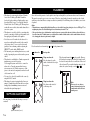
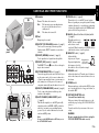
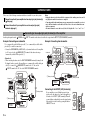
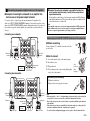
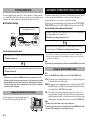
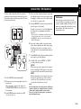
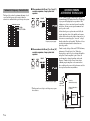
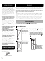
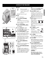
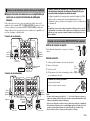
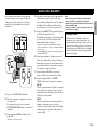
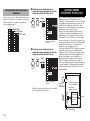
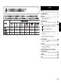
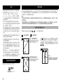
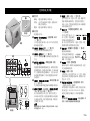
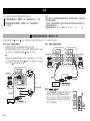
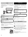
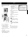
RTL English Español Subwoofer NS-SW500 中文 OWNER’S MANUAL MANUAL DE INSTRUCCIONES Thank you for selecting this YAMAHA product. CAUTION: Read this before operating your unit Please read the following operating precautions before use. YAMAHA will not be held responsible for any damage and/or injury caused by not following the cautions below. • To assure the finest performance, please read this manual carefully. Keep it in a safe place for future reference. • Install this unit in a cool, dry, clean place - away from windows, heat sources, sources of excessive vibration, dust, moisture and cold. Avoid sources of humming (transformers, motors). To prevent fire or electrical shock, do not expose this unit to rain or water. • The voltage to be used must be the same as that specified on the rear panel. Using this unit with a higher voltage than specified is dangerous and may cause a fire and/or electric shock. • Do not use force on switches, controls or connection wires. When moving the unit, first disconnect the power plug and the wires connected to other equipment. Never pull the wires themselves. • When not planning to use this unit for a long period (ie., vacation, etc.), disconnect the AC power plug from the wall outlet. • To prevent lightning damage, disconnect the AC power plug when there is an electric storm. • Since this unit has a built-in power amplifier, heat will radiate from the rear panel. Place the unit apart from the walls, allowing at least 20 cm of space above, behind and on both sides of the unit to prevent fire or damage. Furthermore, do not position with the rear panel facing down on the floor or other surfaces. • Do not cover the rear panel of this unit with a newspaper, a tablecloth, a curtain, etc., in order not to obstruct heat radiation. If the temperature inside the unit rises, it may cause fire, damage to the unit and/or personal injury. i En • Do not place the following objects on this unit: - Glass, china, small metallic, etc. If glass, etc., falls as a result of vibrations and breaks, it may cause bodily injury. - A burning candle etc. If the candle falls as a result of vibration, it may cause fire and bodily injury. - A vessel containing water If the vessel falls as a result of vibration and water spills, it may cause damage to the speaker, and/or you may get an electric shock. • Do not place this unit where foreign material, such as dripping water. It might cause fire, damage to this unit, and/or personal injury. • Never put a hand or a foreign object into the YST port located on the right side of this unit. When moving this unit, do not hold the port, as it might cause personal injury and/or damage to this unit. • Never place a fragile object near the YST port of this unit. If the object falls or drops as a result of the air pressure, it may cause damage to the unit and/or personal injury. • Never open the cabinet. It might cause an electric shock, since this unit uses a high voltage. It might also cause personal injury and/or damage to this unit. If something drops into the set, contact your dealer. • When using a humidifier, be sure to avoid condensation inside this unit by allowing enough space around this unit or avoiding excess humidification. Condensation might cause fire, damage to this unit, and/or electric shock. • Super-bass frequencies reproduced by this unit may cause a turntable to generate a howling sound. In such a case, move this unit away from the turntable. • This unit may be damaged if certain sounds are continuously output at high volume level. For example, if 20 Hz-50 Hz sine waves from a test disc, bass sounds from electronic instruments, etc., are continuously output, or when the stylus of a turntable touches the surface of a disc, reduce the volume level to prevent this unit from being damaged. • If you hear distortion (i.e., unnatural, intermittent “rapping” or “hammering” sounds) coming from this unit, reduce the volume level. Extremely loud playing of a movie soundtrack’s low frequency, bass-heavy sounds or similarly loud popular music passages can damage this speaker system. • Vibration generated by super-bass frequencies may distort images on a TV. In such a case, move this unit away from the TV set. • Do not attempt to clean this unit with chemical solvents as this might damage the finish. Use a clean, dry cloth. • Be sure to read the “TROUBLESHOOTING” section regarding common operating errors before concluding that the unit is faulty. • Install this unit near the wall outlet and where the AC power plug can be reached easily. • Secure placement or installation is the owner’s responsibility. YAMAHA shall not be liable for any accident caused by improper placement or installation of speakers. • VOLTAGE SELECTOR (Asia and General models only) The voltage selector switch on the rear panel of this unit must be set to your local main voltage BEFORE plugging this unit into the AC main supply. Voltages are 110-120 V/220-240 V. Taking care of the speaker TO REDUCE THE RISK OF FIRE OR ELECTRIC SHOCK, DO NOT EXPOSE THIS APPLIANCE TO RAIN OR MOISTURE. To maintain the spotless glossy surface of the polished finish, wipe it with a soft, dry cloth. To avoid damage to the finish, do not apply chemical solvents, such as alcohol, benzine, thinner, insecticide, etc. Also, do not use a damp cloth, or any type of cloth that contains chemical solvents, or place a plastic or vinyl sheet on top of the speaker. Otherwise, the finish may peel, the color may fade, or the sheet may stick to the surface. This unit is not disconnected from the AC power source as long as it is connected to the wall outlet, even if this unit itself is turned off. In this state, this unit is designed to consume a very small quantity of power. Yamaha recommends that you use a Yamaha Unicon cloth (sold separately). For heavy dirt, use a Yamaha Piano Unicon (sold separately). You can purchase a Yamaha Unicon cloth and Piano Unicon at your nearest Yamaha dealer. CONTENTS FEATURES......................................................................1 SUPPLIED ACCESSORY..............................................1 PLACEMENT .................................................................1 Subwoofer orientation.................................................1 CONTROLS AND THEIR FUNCTIONS...................... 2 CONNECTIONS.............................................................3 1 Connecting to line output (pin jack) terminal(s) of the amplifier.......................................................3 2 Connecting to speaker output terminals of the amplifier.......................................................4 Connecting to the INPUT1/OUTPUT terminals of the subwoofer ....................................................................4 SYSTEM CONNECTIONS .......................................5 Plugging the subwoofer into an AC outlet ........................5 AUTOMATIC POWER-SWITCHING FUNCTION ...........5 Setting the AUTO STANDBY switch ........................5 ADJUSTING THE BALANCE......................................6 Subwoofer frequency characteristics ..........................7 ADVANCED YAMAHA ACTIVE SERVO TECHNOLOGY II .........................................................7 TROUBLESHOOTING..................................................8 SPECIFICATIONS .........................................................8 ii En English WARNING FEATURES PLACEMENT • This subwoofer system employs Advanced Yamaha Active Servo Technology II, which Yamaha has developed for the production of higher quality, superbass sound. (Refer to page 7 for details on Advanced Yamaha Active Servo Technology II.) This super-bass sound adds a more realistic, theater-in-the-home effect to your stereo system. • This subwoofer can easily be added to your existing audio system by connecting to either the speaker terminals or the line output (pin jack) terminals of the amplifier. • For effective use of the subwoofer, the subwoofer’s super-bass sound should be matched to the sounds of your front speakers. You can create the best sound quality for various listening conditions by using the HIGH CUT control and the PHASE switch. • The Automatic power-switching function saves you the trouble of pressing the power switch to turn the power on and off. • The subwoofer can be linked to a Yamaha component for simultaneous power on/off operation. Use the supplied system control cable to connect the subwoofer to a Yamaha component that features a system connector jack. When you turn on or off the power to the connected component, the subwoofer will also be turned on or off. • You can select a bass effect suitable for the source by using the B.A.S.S. switch. • This subwoofer system is equipped with a linear port unique to Yamaha that provides smooth bass response during playback, minimizing extraneous noise not included in the original input signal. Since the low-end frequencies of audio signals feature long wavelengths, they are almost non-directional to human ears. The super-bass range does not create a stereo image. Therefore, a single subwoofer may be enough to produce a highquality super-bass sound. However, using two subwoofers (similarly to L and R front speakers) can enhance your acoustic experience. SUPPLIED ACCESSORY After unpacking, check that the following accessory is contained. System control cable (5 m x 1) 1 En Notes • This unit features a magnetically shielded design. However, there is still a chance that placing it too close to a CRT-type TV set might impair picture color. Should this happen, move this unit away from the TV set. • If the speaker volume is very loud, furniture or window glass may resonate and the subwoofer itself may vibrate. In this case, lower the volume level. To limit resonance, use a thick curtain or similar cloth that tends to absorb sound vibrations effectively. Also, changing the subwoofer position may be helpful. Subwoofer orientation Place the subwoofer as shown in fig. : subwoofer A A or B for the optimum effect. : front speaker Using one subwoofer Place the subwoofer on the outside of either the left or right front speaker. The placement shown in fig. C is also possible. However, if the subwoofer system is placed directly facing the wall, the bass effect may suffer due to cancellation of direct and reflected sounds. To prevent this from happening, place the subwoofer system at an angle, as in fig. A or B . C B Using two subwoofers Place them on the outside of each front speaker. Note There may be a case that you cannot obtain enough super-bass sound from the subwoofer due to standing waves. 1 Indicator 1 Green: The subwoofer is turned on. Red: The Automatic power-switching function has activated, and the subwoofer is in standby mode. The subwoofer is turned off. Off: Top panel 3 OUTPUT (TO SPEAKERS) terminals ( page 3) Can be used for connecting to the main speakers. Signals from the INPUT1 terminals are sent to these terminals. 2 Front panel 2 Port Outputs super-bass sound. 4 INPUT2 (NORMAL) terminals ( page 3) Used to input line level signals from the amplifier. 5 INPUT3 (LFE) terminals ( page 3) The HIGH CUT control ! has no effect on the signals input to these terminals. 3 6 4 5 7 8 9 ) 6 SYSTEM CONNECTOR jack ( page 5) Connect the supplied system control cable here. If you use the system control cable to connect a subwoofer to a Yamaha component (that features a system connector jack), turning on or off the power to the connected component automatically turns the subwoofer on or off. 7 INPUT1 (FROM AMPLIFIER) terminals ( page 4) Used to connect the subwoofer with the speaker terminals of the amplifier. ! Rear panel # @ $ 8 AUTO STANDBY (HIGH/LOW/OFF) switch ( page 5) This switch is originally set to the OFF position. By setting this switch to the HIGH or LOW position, the subwoofer’s automatic power-switching function operates. If you do not need this function, leave this switch in the OFF position. Note Be sure to set the POWER switch to OFF before you set the AUTO STANDBY switch. 9 PHASE switch ( page 6) This switch is to be set to the REV (reverse) position. However, depending on your speaker system or listening conditions, there may be a case when better sound quality is obtained by setting this switch to the NORM (normal) position. Select the best position by ear. ) B.A.S.S. (Bass Action Selector System) switch ( page 6) When this switch is set to MUSIC, the bass sound in audio software is well reproduced. When the switch is set to MOVIE, the bass sound in video software is well reproduced. ! HIGH CUT control ( page 6) Adjusts the high frequency cut off point. * One graduation of this control Frequencies higher than represents 10 Hz. the frequency selected by this control are all cut off (and not output). @ VOLUME control Adjusts the volume level. Turn the control clockwise to increase the volume, and counterclockwise to decrease the volume. # POWER switch During normal usage, set this switch to ON. If you plan not to use the subwoofer for a long period of time, set the switch to OFF. $ VOLTAGE SELECTOR switch (Asia and General models only) If the preset setting of the switch is incorrect, set the switch to the proper voltage (110-120 V/220-240 V) of your area. Consult your dealer if you are unsure of the correct setting. WARNING Be sure to unplug the subwoofer before setting the VOLTAGE SELECTOR switch correctly. 2 En English CONTROLS AND THEIR FUNCTIONS CONNECTIONS Choose one of the following connection methods most suitable for your audio system. 1 Choose this method if your amplifier has line output (pin jack) terminal(s). ( this page) 2 Choose this method if your amplifier has no line output (pin jack) terminals. ( page 4) 1 Audio signals input from the Notes • Unplug the subwoofer and other audio/video components before making connections, and do not plug them in until all connections are completed. • Connecting methods and terminal names on your component (such as an amplifier or receiver) may be different from those used in this book. Please refer to the owner’s manual that came with your component. • All connections must be correct, that is to say L (left) to L; R (right) to R; “+” to “+” and “–” to “–”. Connecting to line output (pin jack) terminal(s) of the amplifier /MONO and INPUT 2 terminals on the subwoofer will not be output from the OUTPUT (TO SPEAKERS) terminals. Example: Connecting one subwoofer Example: Connecting two subwoofers Use a commercially-available Mono pin cable 1 or a commercially-available Audio pin cable 2 to make the connections. • Connect the SUBWOOFER (or LOW PASS, etc.) terminal on the rear of the amplifier (or AV receiver) to the /MONO INPUT2 terminal of the subwoofer using a commercially-available Mono pin cable 1. Alternatively, • When connecting the subwoofer to the SPLIT SUBWOOFER terminals (featuring L and R channels) on the rear panel of the amplifier, use a commercially-available Audio pin /MONO INPUT2 terminal to the “L” side, and the cable 2 to connect the INPUT2 terminal to the “R” side of the SPLIT SUBWOOFER terminals. Subwoofer Subwoofer To AC outlet 1 Mono pin cable Subwoofer Amplifier or receiver 2 Audio pin cable To AC outlet 1 Mono pin cable Amplifier or receiver 3 En Connecting to the INPUT3 (LFE) terminal(s) If your amplifier can cut off high frequencies from signals sent to the subwoofer, connect the amplifier to the subwoofer’s INPUT3 (LFE) terminal(s).This will promote higher sound quality because the signal routing in the subwoofer is shortened by passing the built-in HIGH CUT circuit. To AC outlet 1 Mono pin cable Connecting to speaker output terminals of the amplifier ■ Example: Connecting the subwoofer to an amplifier that features one set of speaker output terminals Use speaker cables to connect the speaker output terminals of the amplifier to the subwoofer’s INPUT 1 (FROM AMPLIFIER) terminals. Connect the front speakers to the subwoofer’s OUTPUT (TO SPEAKERS) terminals. Although the subwoofer is connected between the front speakers and the amplifier, the sound volume or quality will not be affected. ■ Example: Connecting the subwoofer to an amplifier featuring two sets of speaker output terminals (A and B) that can output sound signals simultaneously Set the amplifier so that both sets of speaker output terminals (A and B) will output sound signals simultaneously. Then, connect the front speakers to terminals A, and connect the subwoofer to terminals B. Note If your amplifier features two sets of speaker output terminals that do NOT output sound signals simultaneously, please refer to the example for connecting an amplifier that has only one set of speaker output terminals (see the figure on the left). Connecting one subwoofer Connecting to the INPUT1/OUTPUT terminals of the subwoofer ■ Before connecting Remove 10 mm (3/8") of insulation from the ends of the speaker cables. Subwoofer Right front speaker Left front speaker To AC outlet 10 mm (3/8") Good ■ How to connect 1. Loosen the terminal’s knob, as shown in the figure. 1 2. Insert the bare wire. Amplifier or receiver Speaker output terminals 3. Tighten the knob. Red: positive (+) 4. Test the firmness of the connection by pulling lightly Black: negative (–) on the cable at the terminal. Connecting two subwoofers ■ Connecting the banana plug 1. Tighten the terminal knob. 2. Simply insert the banana plug into the terminal. Right front speaker Left front speaker Subwoofer Speaker output terminals Subwoofer Amplifier or receiver To AC outlet To AC outlet No Good 2 3 1 2 Notes • Make sure that the “+” and “–” polarity markings of the speaker cables are observed and set correctly. If these cables are reversed, the sound will be unnatural and lack bass. • Do not let the bare speaker wires touch each other, because this could damage the subwoofer or the amplifier. • If the connections are faulty, no sound will be heard from the subwoofer or the speakers. Do not insert the insulation into the hole. Sound may not be produced. • To avoid accidents resulting from tripping over loose speaker cables, fix them to the floor. 4 En English 2 SYSTEM CONNECTIONS AUTOMATIC POWER-SWITCHING FUNCTION If you use the supplied system control cable to connect a subwoofer to a Yamaha component (e.g., Yamaha Digital Sound Projector that features a system connector jack), turning on or off the power to the connected component automatically turns the subwoofer on or off. This function automatically places the subwoofer in standby mode if the subwoofer does not detect a signal from the amplifier for a certain period of time. The subwoofer automatically turns on as soon as it detects a signal from the amplifier. The Automatic power-switching function works as follows when the AUTO STANDBY (HIGH/LOW/OFF) switch is set to LOW or HIGH. (Normally, set the switch to LOW.) How the Automatic power-switching function works ■ Connection example Yamaha Digital Sound Projector The subwoofer automatically enters standby mode if it does not receive an input signal (*1) from the amplifier for 7 or 8 minutes (*2). * The indicator color changes from green to red. Subwoofer Supplied system control cable When the subwoofer detects an input signal (*1) from the amplifier, the subwoofer automatically turns on. * The indicator color changes from red to green. How the System Connection works *1 When the Automatic power-switching function is enabled, the subwoofer will detect a bass signal input of Turning on the power to the connected component will automatically turn on the subwoofer. * The indicator lights green. below 200Hz (such as sound effects of explosion in action movies, bass guitar or bass drum sound, etc.). *2 This value may vary depending on the system environment. For example, it may be affected by noise generated from other equipment. Note The Automatic power-switching function is available only when the POWER switch is set to ON. Turning off the power to the connected component will automatically turn off the subwoofer. * The indicator turns off. Notes • For this feature to be available, the POWER switch on the subwoofer must be set to ON. • Powering on/off via the system connection takes priority over the Automatic power-switching function. (While the unit is turned on, the Automatic power-switching function is enabled.) • To modify the settings of the connected components, please refer to the owner’s manual that came with the respective component. Plugging the subwoofer into an AC outlet After all connections are completed, plug the subwoofer and other audio/video components into AC outlets. Setting the AUTO STANDBY switch Note Be sure to set the POWER switch to OFF before you set the AUTO STANDBY switch. LOW: The Automatic power-switching function activates at a certain level of input signal. To enable the function, select this position. HIGH:If the Automatic power-switching function does not work well when the AUTO STANDBY switch is set to LOW, select this position. If the function still does not work, slightly raise the LFE LEVEL on the amplifier. OFF: The Automatic power-switchingy function may unexpectedly activate due to the system environment, for example, if the subwoofer detects noise generated from the peripheral components. In this case, select this position to disable the Automatic powerswitching function, and manually turn the unit on or off by using the POWER switch. Notes • The subwoofer uses a small amount of power in auto-standby mode. • If you plan not to use the subwoofer for a long period of time, set the POWER switch on the rear panel to OFF, or unplug the power cable from the AC outlet. To AC outlet 5 En English ADJUSTING THE BALANCE To achieve natural sound with an effective super-bass component, you must adjust the volume and tone balance between the subwoofer and the front speakers. Follow the procedure described below. 4. Play a source that contains low-frequency components and adjust the output level of the front speakers using the amplifier’s volume control to the desired listening level. (Set all tone controls to flat.) 5. Adjust the HIGH CUT control to the position where the desired response can be obtained. Normally, set the control to a level a little higher than the front speaker’s rated minimum reproducible frequency*. PHASE switch In most situations, set this switch to select the reverse mode. However, depending on your speaker systems or listening condition, there may be a case when better sound quality is obtained by selecting the normal mode. Select the better mode by monitoring the sound. * The front speaker’s rated minimum reproducible frequency can be looked up in the speakers’ catalog or owner’s manual. * The HIGH CUT control has no effect on signals input to the INPUT 3 LFE terminals. 6. Increase the volume gradually to adjust the volume balance between the subwoofer and the front speakers. Normally, set the control to a level where you can obtain a little more bass effect than when the subwoofer is not used. 7. Set the PHASE switch to the position which yields the more natural (or preferable) phasing. 8. Set the B.A.S.S. switch to “MOVIE” or “MUSIC” Rear panel 1. Set the VOLUME control to minimum (0). 2. Turn on the power to the component(s) connected to the subwoofer. If the component is connected to the subwoofer’s SYSTEM CONNECTOR jack, turn on the power to that component. 3. Set the POWER switch on the subwoofer to ON. * The indicator lights green. according to the played source. MOVIE: When a movie type source is played, the low-frequency effects are enhanced to allow listeners to enjoy a more powerful sound. (The sound will be richer and deeper.) MUSIC: When an ordinary music source is played, the excessive low-frequency components are cut off to make the sound clearer. (The sound will carry less bass and reproduce the melody line more clearly.) Note Once the volume balance between the subwoofer and the front speakers is adjusted, you can adjust the volume of your entire sound system by using the amplifier’s volume control. However, if you replace the front speakers, you will need to make this adjustment again. 6 En Subwoofer frequency characteristics The figures below show the optimum adjustment of each control and the frequency characteristics when the subwoofer is combined with a typical front speaker system. HIGH CUT 40 Hz HIGH CUT 90 Hz HIGH CUT 140 Hz dB 90 ■ When combined with 10 cm (4") or 13 cm (5") acoustic suspension, 2-way system front speakers PHASE dB 90 80 (70 Hz) (REV) 70 80 60 70 50 60 40 20 Front speaker 50 100 200 500Hz Frequency response graph* 50 40 20 50 100 200 500Hz ■ When combined with 20 cm (8") or 25 cm (10") acoustic suspension, 2-way system front speakers dB PHASE 90 80 (50 Hz) (REV) 70 60 ADVANCED YAMAHA ACTIVE SERVO TECHNOLOGY II In 1988, Yamaha brought to the marketplace speaker systems utilizing YST (Yamaha Active Servo Technology) to give powerful, high quality bass reproduction. This technique uses a direct connection between the amplifier and speaker, allowing accurate signal transmission and precise speaker control. As this technology uses speaker units controlled by the negative impedance drive of the amplifier and resonance generated between the speaker cabinet volume and port, it creates more resonant energy (the “air woofer” concept) than the standard bass reflex method. This allows for bass reproduction from much smaller cabinets than was previously possible. Yamaha’s newly developed Advanced YST II adds many refinements to Yamaha Active Servo Technology, allowing better control of the forces driving the amplifier and speaker. From the amplifier’s point of view, the speaker impedance changes depending on the sound frequency. Yamaha developed a new circuit design combining negative-impedance and constant-current drives, which provides a more stable performance and clear bass reproduction, without any murkiness. Front speaker Cabinet 50 40 20 50 100 200 Port 500Hz Frequency response graph* * This diagram does not depict actual frequency response characteristics. Highamplitude bass sound Air woofer (Helmholtz resonator) Advanced impedance Converter Active Servo Processing Amplifier Signals of low amplitude 7 En Signals Refer to the chart below if this unit does not function properly. If the problem you are experiencing is not listed below, or if the instructions given below do not help, disconnect the power cord and contact an authorized YAMAHA dealer or service center. Problem Cause What to Do The subwoofer does not enter standby mode automatically. Noise generated from external appliances etc., is activating the subwoofer. Move the subwoofer farther away from such appliances, and/or reposition the connected speaker cables. Set the AUTO STANDBY switch to the HIGH or LOW position. The AUTO STANDBY switch is set to the OFF position. Set the AUTO STANDBY switch to the HIGH or LOW position. The subwoofer enters standby mode unexpectedly. The level of input signal is too low. Set the AUTO STANDBY switch to the HIGH position, and increase the output level of the amplifier. The subwoofer turns on unexpectedly. Noise generated from external appliances etc., is activating the subwoofer. Move the subwoofer farther away from such appliances, and/ or reposition the connected speaker cables. If the AUTO STANDBY switch is set to HIGH, set it to LOW. Alternatively, set the AUTO STANDBY switch to the OFF position. Problem Cause What to Do Power is not supplied even though the POWER switch is set to the ON position. The power plug is not securely connected. Connect it securely. The subwoofer does not turn on automatically via the system connection. The system control cable is not connected properly or securely. Connect the system control cable properly. The POWER switch is set to OFF. Set the POWER switch to ON. No sound. The volume is set to minimum. Increase the volume. Speaker cables are not connected securely. Connect speaker cables securely. Speaker cables are not connected correctly. Connect them correctly, that is L (left) to L; R (right) to R; “+” to “+” and “–” to “–”. The PHASE switch is not set correctly. Set the PHASE switch to the other position. A source sound with little bass frequency content is being played. Play a source sound with bass frequencies. Set the HIGH CUT control to a higher position. The sound is influenced by standing waves. Reposition the subwoofer or break up parallel surfaces by placing bookshelves, etc., along the walls. The POWER switch is set to the OFF position. Set the POWER switch to the ON position. The AUTO STANDBY switch is set to the OFF position. Set the AUTO STANDBY switch to the HIGH or LOW position. The level of input signal is too low. Set the AUTO STANDBY switch to the HIGH position, and increase the output level of the amplifier. Type ............................................................. Advanced Yamaha Active Servo Technology Driver ........................................................................................... 25 cm (10") cone woofer Magnetic shielding type Amplifier Output (100 Hz, 5 ohms, 10% THD) .................................................... 250 W Frequency Response .................................................................................. 20 Hz - 160 Hz Power Supply U.K. and Europe models ...................................................................... AC 230 V, 50 Hz Australia model .................................................................................... AC 240 V, 50 Hz China model ......................................................................................... AC 220 V, 50 Hz Asia and General models ......................................... AC 110-120/220-240 V, 50/60 Hz Power Consumption................................................................................................... 80 W Standby Power Consumption ...................................................................... 0.3 W or less Dimensions (W × H × D)......................... 380 × 368 × 420 mm (15" × 14-1/2" × 16-1/2") Weight ............................................................................................. 18.5 kg (40 lbs. 13 oz.) No bass frequency content is being output from the amplifier. Check the bass output setting of the amplifier. Please note that all specifications are subject to change without notice. Sound level is too low. The subwoofer does not turn on automatically. SPECIFICATIONS 8 En English TROUBLESHOOTING Gracias por haber elegido este producto YAMAHA. PRECAUCIÓN: Lea atentamente las siguientes indicaciones antes de utilizar este aparato. Lea las siguientes precauciones de funcionamiento antes usar este aparato por primera vez. YAMAHA no se responsabilizará de cualquier daño o lesión provocada por no seguir las precauciones que aparecen a continuación. • Lea cuidadosamente este manual para obtener el mejor rendimiento posible. Manténgalo en un lugar seguro para utilizarlo como referencia en el futuro. • Instale la unidad en un lugar fresco, seco y limpio, alejado de ventanas, aparatos que produzcan calor, lugares con muchas vibraciones, polvo, humedad o frío. Evite aparatos que causen ruidos de zumbido (transformadores y motores). Para evitar incendios o descargas eléctricas, no exponga el altavoz a la lluvia o al agua. • El voltaje que se debe utilizar ha de ser el mismo que el especificado en el panel trasero. Si utiliza esta unidad con un voltaje superior al especificado podría provocar un incendio o descargas eléctricas. • No fuerce los interruptores, controles o cables de conexión. Cuando mueva esta unidad, desconecte primero el cable de alimentación y los cables conectados con otros equipos. No tire nunca de los cables. • Si no va a utilizar el aparato durante un período de tiempo prolongado (por ejemplo, durante las vacaciones, etc.) desconecte el enchufe de alimentación de CA de la toma de corriente. • Para evitar daños debidos a los relámpagos, desenchufe el cable de alimentación de CA durante las tormentas eléctricas. • Este sistema irradia calor por el panel trasero porque tiene un amplificador de potencia incorporado. Coloque la unidad separada de las paredes dejando al menos 20 cm de espacio encima, detrás y a ambos lados de la unidad para evitar un incendio o cualquier otro tipo de daño. Tampoco se debe colocar con el panel trasero contra el suelo o apoyado sobre otras superficies. • No cubra el panel trasero de la unidad con papeles de periódicos, manteles, cortinas y otros para no obstruir la radiación de calor. Si aumenta la temperatura en el i Es • • • • • • • interior de la unidad, podría provocar incendios, averías en la unidad o lesiones personales. No coloque los siguientes objetos sobre esta unidad: - Cristal, porcelana, pequeños objetos metálicos, etc. Se podrían producir lesiones personales si el cristal u otros objetos se caen y se rompen como resultado de las vibraciones. - Velas encendidas, etc. Si la vela se cae por las vibraciones, se puede provocar incendios y lesiones personales. - Recipientes con agua Si el recipiente se cae por las vibraciones y se derrama el agua, se podrían provocar daños en el altavoz o recibir descargas eléctricas. No coloque la unidad en un lugar en donde puedan caer objetos extraños como gotas de agua. Podría provocar un incendio, dañar el altavoz o sufrir lesiones personales. No ponga nunca ponga las manos o un objeto extraño en el puerto YST situado a la derecha de esta unidad. Cuando mueva la unidad, no toque el puerto, ya que podría causar lesiones personales o la unidad podría averiarse. Nunca coloque un objeto frágil cerca del puerto YST de esta unidad. Si el objeto se cae o se vuelca debido a la presión del aire, podría provocar averías en la unidad o lesiones personales. No abra nunca la carcasa. Podría provocar una descarga eléctrica, ya que esta unidad es de alto voltaje. También podría provocar lesiones personales o averiar la unidad. Si algo cae en el equipo, póngase en contacto con su distribuidor. Si utiliza un humidificador, es muy importante evitar la condensación dentro esta unidad. Para ello, deje siempre suficiente espacio alrededor de esta unidad y evite el exceso de humidificación. La condensación podría causar un incendio, averiar la unidad o producir una descarga eléctrica. Las frecuencias de ultragraves generadas por esta unidad pueden hacer que el tocadiscos emita un sonido de aullido. En este caso, aleje la unidad del tocadiscos. • La unidad podría averiarse si se escucharan continuamente ciertos sonidos en el nivel máximo de volumen. Por ejemplo, si se escuchan ondas sinusoidales de 20 Hz-50 Hz con el disco de prueba, sonidos graves de instrumentos electrónicos, etc.; o cuando la aguja del tocadiscos toque la superficie de un disco, reduzca el nivel de volumen para evitar que se dañe el equipo. • Si se escuchan sonidos distorsionados (por ejemplo, sonidos raros, “golpeteos” o “martilleos” intermitentes) provenientes de la unidad, baje el nivel del volumen. Este sistema de altavoces se puede averiar si se reproducen a un volumen extremadamente elevado las bajas frecuencias de las películas, los sonidos con graves fuertes o música de similares características. • La vibración generada por las frecuencias ultragraves puede distorsionar las imágenes de un televisor. En este caso, aleje el sistema del televisor. • No limpie la unidad con disolventes químicos: podría dañar el acabado. Utilice un paño limpio y seco para la limpieza. • No se olvide de consultar la sección “RESOLUCIÓN DE AVERÍAS” antes de dar por concluido que su aparato está averiado. • Instale esta unidad cerca de la toma de CA y donde se pueda alcanzar fácilmente la clavija de alimentación. • La instalación en un lugar seguro es responsabilidad del propietario. YAMAHA no se hace responsable de ningún accidente provocado por una instalación incorrecta del altavoz. • VOLTAGE SELECTOR (Únicamente modelos para Asia y General) El selector de tensión del panel posterior de este aparato se deberá poner en la posición que corresponda a la tensión empleada localmente ANTES de conectar el aparato con la red de alimentación de CA. Las tensiones son 110-120 V / 220-240 V. Cuidados del altavoz PARA REDUCIR EL RIESGO DE INCENDIOS Y DESCARGAS ELÉCTRICAS, NO EXPONGA ESTA UNIDAD A LA LLUVIA O A LA HUMEDAD. Para mantener impoluta la superficie satinada del acabado brillante, límpiela con un paño seco y suave. Para evitar dañar el acabado, no aplique disolventes químicos como el alcohol, bencina, disolventes, insecticidas, etc. No utilice tampoco un trapo húmedo o cualquier tipo de trapo que contenga disolventes químicos ni coloque una lámina de plástico o de vinilo encima del altavoz. Si lo hace, el acabado podría pelarse, el color desvanecerse o la lámina podría adherirse a la superficie. Esta unidad no se desconecta de la fuente de alimentación de CA si está conectada en una toma de CA, incluso si la propia unidad está apagada. En tal estado, la unidad está diseñada para consumir una cantidad de corriente muy pequeña. Yamaha recomienda la utilización de un paño Unicon de Yamaha (de venta por separado). Si hay mucha suciedad, utilice Unicon para Piano de Yamaha (de venta por separado). Puede adquirir paños Unicon de Yamaha y Unicon para Piano en el concesionario Yamaha más cercano. CONTENIDO CARACTERÍSTICAS ....................................................1 ACCESORIO SUMINISTRADO ..................................1 UBICACIÓN....................................................................1 Orientación del subwoofer..........................................1 CONTROLES Y SUS FUNCIONES.............................2 CONEXIONES................................................................3 1 Conexión con los terminales (con clavija) de salida de línea del amplificador..........................................3 2 Conexión con los terminales de salida de los altavoces del amplificador ...........................4 Conexión con los terminales INPUT1/OUTPUT del subwoofer ....................................................................4 CONEXIONES DEL SISTEMA ................................5 Enchufe del subwoofer en una toma de CA ......................5 FUNCIÓN DE ENCENDIDO AUTOMÁTICO ...........5 Configuración del interruptor AUTO STANDBY ......5 AJUSTE DEL BALANCE..............................................6 Características de frecuencias del subwoofer .............7 ADVANCED YAMAHA ACTIVE SERVO TECHNOLOGY II .........................................................7 RESOLUCIÓN DE AVERÍAS.......................................8 ESPECIFICACIONES ...................................................8 ii Es Español ADVERTENCIA CARACTERÍSTICAS UBICACIÓN • Este sistema de subwoofers emplea la tecnología avanzada de servo activo de Yamaha (Advanced Yamaha Active Servo Technology II) desarrollada para reproducir sonidos ultragraves de alta calidad. (Consulte más detalles sobre Advanced Yamaha Active Servo Technology II en la página página 7.) Este sonido de ultragraves añade a su sistema estéreo un efecto más realista de cine en casa. • Este subwoofer se puede agregar fácilmente al sistema de audio existente conectándolo en los terminales de altavoces o en los terminales de salida de línea (con clavija) del amplificador. • Para usar el subwoofer con efectividad, el sonido de ultragraves del subwoofer deberá coincidir con el de los altavoces principales. Podrá obtener un sonido de mayor calidad utilizando el control HIGH CUT y el interruptor PHASE. • La función de encendido automático le ahorra la molestia de pulsar el interruptor POWER para conectar y desconectar la alimentación. • El subwoofer se puede conectar con un componente Yamaha para su encendido y apagado simultáneos. Utilice el cable de control del sistema que se suministra para conectar el subwoofer con un componente Yamaha que cuente con un terminal de conexión del sistema. Cuando encienda o apague el componente conectado, el subwoofer también se apagará o encenderá. • Puede seleccionar el efecto de graves adecuado para la fuente utilizando el interruptor B.A.S.S. • Este sistema de ultragraves está equipado con un puerto lineal exclusivo de Yamaha que proporciona una respuesta suave de graves durante la reproducción, reduciendo al mínimo el ruido externo no incluido en la señal de entrada original. Dado que las frecuencias más bajas de las señales de audio disponen de amplias longitudes de onda, son prácticamente no direccionales para el oído humano. La gama de ultragraves no crea una imagen estéreo. Por lo tanto, un único subwoofer puede ser suficiente para producir un sonido de ultragraves de alta calidad. Sin embargo, la utilización de dos subwoofers (parecido a los altavoces principales L y R) puede realzar su experiencia acústica. ACCESORIO SUMINISTRADO Después de retirar el embalaje, compruebe que la caja contiene el siguiente accesorio. Cable de control del sistema (5 m x 1) 1 Es Notas • Esta unidad cuenta con un diseño con protección magnética. No obstante, todavía existe la posibilidad de que su ubicación demasiado cerca de un televisor con tubo de rayos catódicos afecte al color de la imagen. En tal caso, aleje esta unidad del televisor. • Si el volumen del altavoz es demasiado alto, los muebles o los cristales pueden resonar e incluso el propio subwoofer podría vibrar. En tal caso, baje el nivel del volumen. Para limitar la resonancia, utilice una cortina gruesa o un tejido similar que absorba con efectividad las vibraciones del sonido. Cambiar la ubicación del subwoofer también puede resultar útil. Orientación del subwoofer Coloque el subwoofer como se muestra en la figura : subwoofer A A o B para conseguir el efecto óptimo. : altavoz delantero Utilización de un subwoofer Coloque el subwoofer en el exterior del altavoz derecho o izquierdo principal. La ubicación indicada en la fig. C también es posible. Sin embargo, si el sistema del subwoofer se coloca orientado directamente a la pared, el efecto de los graves podría perderse debido a la cancelación de los sonidos directos y reflejados. Para evitar que esto suceda, coloque el sistema de ultragraves en ángulo, tal como se indica en la fig. A o B . C B Utilización de dos subwoofers Colóquelos en el exterior de ambos altavoces principales. Nota Se puede dar el caso de que no se logren suficientes sonidos de ultragraves desde el subwoofer debido a las ondas estacionarias. CONTROLES Y SUS FUNCIONES El subwoofer está encendido. Se ha activado la función de encendido automático y el subwoofer está en el modo de espera. Desactivado: El subwoofer está apagado. Panel superior 2 Panel delantero 3 6 4 5 8 7 ! # Panel trasero 9 @ $ ) 2 Puerto Da salida a sonidos ultragraves. 3 Terminales OUTPUT (TO SPEAKERS) ( página 3) Se pueden utilizar para conectarse con los altavoces principales. Las señales desde los terminales INPUT1 se envían a estos terminales. 4 Terminales INPUT2 (NORMAL) ( página 3) Utilizados para introducir señales de nivel de línea desde el amplificador. 5 Terminales INPUT3 (LFE) ( página 3) El control HIGH CUT ! no tiene ningún efecto sobre las señales introducidas en estos terminales. 6 Terminal SYSTEM CONNECTOR ( página 5) Conecte aquí correctamente el cable de control del sistema que se suministra. Si utiliza un cable de control del sistema para conectar un subwoofer con un componente Yamaha (que cuente con un terminal de conexión del sistema), el subwoofer se encenderá o apagará automáticamente cuando se encienda o se apague el componente conectado. 7 Terminales INPUT1 (FROM AMPLIFIER) ( página 4) Utilizados para conectar el altavoz de ultragraves con los terminales de altavoz del amplificador. 8 Interruptor AUTO STANDBY (HIGH/LOW/OFF) ( página 5) Este interruptor está ajustado, originalmente, en la posición OFF. La función de encendido automático del subwoofer se activará cuando se ponga este interruptor en las posiciones HIGH o LOW. Si no necesita esta función, deje el interruptor en la posición OFF. Nota Asegúrese de poner el interruptor POWER en OFF antes de configurar el interruptor AUTO STANDBY. 9 Interruptor PHASE ( página 6) Este interruptor se debe poner en la posición REV (invertida). Sin embargo, en función del sistema de altavoces o de las condiciones de escucha, puede darse el caso de que la calidad del sonido sea mejor si se pone en la posición NORM (normal). Seleccione de oído la mejor posición. ) B.A.S.S. (Sistema de selección de acción de graves) ( página 6) Cuando este interruptor está en MUSIC, se reproducen bien los sonidos graves en los programas de audio. Cuando este interruptor está en MOVIE, se reproducen bien los sonidos graves en los programas de video. ! Control HIGH CUT ( página 6) Ajusta el punto de corte de * Un paso altas frecuencias. de este control Las frecuencias superiores representa a la frecuencia seleccionada 10 Hz. por este control se cortarán (y no habrá salida). @ Control VOLUME Ajusta el nivel del volumen. Gire el control hacia la derecha para subir el volumen y a la izquierda para bajarlo. # Interruptor POWER Durante la utilización normal, ponga este interruptor en “ON.” Ponga en “OFF” el interruptor si no piensa utilizar el subwoofer durante un período prolongado de tiempo. $ Interruptor VOLTAGE SELECTOR (Solamente en modelos para Asia y generales) Si la presente configuración de tensión no es correcta, ajuste el interruptor a la tensión adecuada de su zona (110-120 V/220-240 V). Consulte a su distribuidor en caso de no estar seguro de la configuración correcta. ADVERTENCIA Es muy importante desenchufar el altavoz de ultragraves antes de configurar correctamente el interruptor VOLTAGE SELECTOR. 2 Es Español 1 Indicador Verde: Rojo: 1 CONEXIONES Elija entre los siguientes el método de conexión que mejor se ajuste a su sistema de audio. 1 Elija este método si su amplificador tiene terminales de salida (con clavija) de línea. ( esta página) 2 Elija este método si su amplificador no tiene terminales de salida (con clavija) de línea. ( página 4) 1 Notas • Desenchufe el subwoofer y otros componentes de audio y video antes de realizar las conexiones, y no los vuelva a enchufar hasta que se hayan realizado todas las conexiones. • Los métodos de conexión y los nombres de los terminales en su componente (por ejemplo, amplificador o receptor) pueden ser distintos de los que se emplean en este manual. Consulte el manual del usuario que venía con su componente. • Todas las conexiones deben ser correctas, esto es, L (izquierdo) con L, R (derecho) con R, “+” con “+” y “–” con “–”. Conexión con los terminales (con clavija) de salida de línea del amplificador Las señales de audio que entran desde los terminales /MONO y INPUT 2 del subwoofer no saldrán por los terminales OUTPUT (TO SPEAKERS). Ejemplo: Conexión de un subwoofer Ejemplo: Conexión de dos subwoofers Para realizar las conexiones, utilice un cable monoaural con clavija 1 o un cable de audio con clavija 2 de los que se venden en los comercios. • Conecte el terminal SUBWOOFER (o LOW PASS, etc.) en la parte trasera del amplificador (o receptor A/V) con el terminal /MONO INPUT2 del subwoofer empleando un cable monoaural con clavija 1 de venta en los comercios. Alternativamente, • Cuando conecte el subwoofer en los terminales SPLIT SUBWOOFER (que cuenta con canales L y R) en el panel trasero del amplificador, utilice un cable de audio con clavijas 2, de venta en los comercios, para conectar el terminal /MONO INPUT2 en el lado “L”, y el terminal INPUT2 en el lado “R” de los terminales SPLIT SUBWOOFER. Subwoofer Subwoofer A la toma de corriente de CA A la toma de corriente de CA 1 Cable monoaural con clavija 1 Cable monoaural con clavija Subwoofer Amplificador o receptor 2 Cable de audio con clavija Conexión con los terminales INPUT3 (LFE) A la toma de corriente de CA 1 Cable monoaural con clavija Amplificador o receptor 3 Es Si el amplificador puede cortar las frecuencias altas de las señales enviadas al subwoofer, conecte el amplificador en los terminales INPUT3 (LFE) del subwoofer. Conseguirá una mejor calidad de sonido porque la ruta de la señal en el subwoofer se acortará al pasar por el circuito HIGH CUT incorporado. 2 Conexión con los terminales de salida de los altavoces del amplificador ■ Ejemplo: Conexión del subwoofer con un amplificador que cuenta con un conjunto de terminales de salida para altavoces Conexión de un subwoofer dos conjuntos de terminales de salida para altavoces (A y B) y que puede dar salida simultánea a las señales de sonido Configure el amplificador de forma que ambos conjuntos de terminales (A y B) de salida para altavoces emitan señales de sonido simultáneamente. Conecté a continuación los altavoces delanteros en los terminales A y conecte el subwoofer en los terminales B. Nota Si su amplificador cuenta con dos conjuntos de terminales de salida para altavoces que NO da salida simultánea a las señales de sonido, consulte por favor el ejemplo para conectar un amplificador que cuente con un único conjunto de terminales de salida para altavoces (ver figura a la izquierda). Conexión con los terminales INPUT1/OUTPUT del subwoofer ■ Antes de conectar el aparato Subwoofer Altavoz derecho delantero Altavoz izquierdo delantero Bien ■ Como conectar: 1. Afloje la perilla del terminal como se muestra en la figura. A la toma de corriente de CA Amplificador o receptor 2. Inserte el cable pelado. Terminales de salida de altavoces 3. Apriete la perilla. 4. Tire ligeramente de los cables en el terminal para verificar Conexión de dos subwoofers Altavoz derecho delantero Altavoz izquierdo delantero Terminales de salida de altavoces Subwoofer Amplificador o receptor A la toma de corriente de CA Mal 2 1 Rojo: positivo (+) 3 Negro: negativo (–) que está firmemente conectado. ■ Conexión de la clavija tipo banana 1. Apriete la perilla del terminal. 2. Inserte la clavija tipo banana en el terminal. Subwoofer 10 mm Retire 10 mm del aislamiento de los extremos de cada cable de altavoz. A la toma de corriente de CA 1 2 Notas • Asegúrese de que las marcas de polaridad “+” y “–” de los cables de altavoz se respetan y se ajustan correctamente. Si dichos cables están conectados con la polaridad invertida, el sonido tendrá poca naturalidad y sentirá que faltan graves. • No deje que los cables pelados se toquen; si lo hace, se podría averiar el subwoofer o el amplificador. • Si las conexiones son defectuosas, no se escuchará ningún sonido desde el subwoofer o desde los altavoces. No introduzca el aislante en el orificio. Es posible que el sonido no salga. • Fije los cables de los altavoces al suelo para evitar tropiezos y accidentes. 4 Es Español Utilice cables para altavoces para conectar los terminales de salida de altavoces del amplificador con los terminales INPUT 1 (FROM AMPLIFIER) del subwoofer. Conecte los altavoces delanteros en los terminales OUTPUT (TO SPEAKERS) del subwoofer. Aunque el subwoofer esté conectado entre los altavoces delanteros y el amplificador, esto no afectará al volumen o calidad del sonido. ■ Ejemplo: Conexión del subwoofer con un amplificador que cuenta con CONEXIONES DEL SISTEMA FUNCIÓN DE ENCENDIDO AUTOMÁTICO Si utiliza el cable de control del sistema que se suministra para conectar un subwoofer con un componente Yamaha (por ejemplo, un Yamaha Digital Sound Projector que cuente con terminal de conexión del sistema), el subwoofer se encenderá o apagará automáticamente cuando se encienda o se apague el componente conectado. Esta función coloca automáticamente el subwoofer en el modo de espera si el subwoofer no detecta una señal del amplificador tras un período determinado de tiempo. El subwoofer se enciende automáticamente tan pronto como detecta una señal desde el amplificador. La función de encendido automático funciona de la siguiente forma cuando el interruptor AUTO STANDBY (HIGH/LOW/OFF) está en LOW o HIGH. (Habitualmente, ponga el interruptor en LOW.) ■ Ejemplo de conexión Yamaha Digital Sound Projector Funcionamiento de la función de encendido automático El subwoofer entra automáticamente en el modo de espera si no recibe una señal de entrada (*1) desde el amplificador después de 7 u 8 minutos (*2). * El color del indicador cambia de verde a rojo. Subwoofer Cable de control del sistema suministrado El subwoofer se encenderá automáticamente cuando detecte una señal de entrada (*1) desde el amplificador. * El color del indicador cambia de rojo a verde. Funcionamiento de la conexión del sistema El subwoofer se encenderá automáticamente cuando se encienda el componente conectado. * El indicador se enciende en verde. El subwoofer se apagará automáticamente cuando se apague el componente conectado. * El indicador se apaga. Notas • Para que esta función esté disponible, el interruptor POWER del subwoofer debe estar en ON. • El encendido y apagado mediante conexión del sistema tiene prioridad sobre la función de encendido automático. (Cuando la unidad está encendida, la función de encendido automático está activada.) • Para modificar la configuración de los componentes conectados, consulte por favor el manual del usuario que venía con el componente correspondiente. Enchufe del subwoofer en una toma de CA Enchufe el subwoofer y otros componentes de audio y video en las tomas de CA después de realizar todas las conexiones. A la toma de corriente de CA 5 Es *1 Cuando la función de encendido automático esté activada, el subwoofer detectará una señal de graves por debajo de 200Hz (por ejemplo los efectos sonoros de la explosión en las películas de acción, los bajos o el sonido de graves de la batería, etc.). *2 Este valor puede variar en función del entorno del sistema. Por ejemplo, el ruido generado por otros equipos pueden afectarle. Nota La función de encendido automático únicamente está disponible cuando el interruptor POWER está en ON. Configuración del interruptor AUTO STANDBY Nota Asegúrese de poner el interruptor POWER en OFF antes de configurar el interruptor AUTO STANDBY. LOW: La función de encendido automático se activa con un determinado nivel de la señal de entrada. Seleccione esta posición para habilitar la función. HIGH: Seleccione esta posición si la función de encendido automático no funciona bien cuando el interruptor AUTO STANDBY está en LOW. Si la función sigue sin funcionar, incremente ligeramente el nivel LFE LEVEL del amplificador. OFF: La función de encendido automático podría activarse inesperadamente debido al entorno del sistema, por ejemplo, si el subwoofer detecta el ruido generado por los componentes periféricos. En tal caso, seleccione esta posición para deshabilitar la función de encendido automático, y encienda y apague manualmente la unidad utilizando el interruptor POWER. Notas • El subwoofer utiliza una pequeña cantidad de energía en el modo de espera automático. • Ponga en OFF el interruptor POWER del panel trasero o desconecte el cable de alimentación de la toma de corriente si no piensa utilizar el subwoofer durante un período prolongado de tiempo. AJUSTE DEL BALANCE 4. Reproduzca una fuente que contenga componentes de bajas frecuencias y ajuste el nivel de salida de los altavoces delanteros utilizando el control del volumen del amplificador hasta obtener el nivel de escuchar deseado. (Ponga a cero todos los controles de tono.) 5. Ponga el control HIGH CUT en la posición en la que se pueda obtener la respuesta deseada. Normalmente hay que poner el control en un nivel un poco más alto que el de la frecuencia reproducible nominal mínima del altavoz delantero*. * La frecuencia reproducible nominal mínima de los altavoces delanteros se encuentra en el catálogo o en el manual del usuario de los altavoces. * El control HIGH CUT no afecta a las señales que entran en los terminales INPUT 3 LFE. Nota Cuando se haya ajustado el balance del volumen entre el subwoofer y los altavoces principales, podrá ajustar el volumen de todo su sistema de sonido empleando el control de volumen del amplificador. Sin embargo, si cambia los altavoces principales, tendrá que realizar de nuevo este ajuste. Interruptor PHASE En la mayoría de las situaciones, configure este interruptor para seleccionar el modo inverso. Sin embargo, en función del sistema de altavoces o de las condiciones de escucha, puede darse el caso de que se obtenga una mejor calidad del sonido seleccionando el modo normal. Seleccione el modo más apropiado controlando el sonido. 6. Incremente gradualmente el volumen para ajustar el balance entre el subwoofer y los altavoces delanteros. En general, hay que poner el control en un nivel en el que pueda obtener un efecto de graves un poco superior al de cuando no se emplea el subwoofer. 7. Ponga el interruptor PHASE en la posición que produzca el ajuste de fases más natural o preferible. 8. Ponga el interruptor B.A.S.S. en “MOVIE” o Panel trasero 1. Ponga el control VOLUME al mínimo (0). 2. Encienda el componente o componentes conectados con el subwoofer. Si el componente está conectado en el terminal SYSTEM CONNECTOR del subwoofer, encienda ese componente. 3. Ponga el interruptor POWER del subwoofer en la “MUSIC” en función de la fuente que se reproduzca. MOVIE: Cuándo se reproducen fuentes de películas, se mejoran los efectos de bajas frecuencias para que los oyentes puedan disfrutar de un sonido más potente. (El sonido será más rico y más profundo.) MUSIC: Cuando se reproducen fuentes de música normales, se eliminan los componentes excesivos de bajas frecuencias para que el sonido sea más claro. (El sonido tendrá menos graves y reproducirá la línea melódica con más claridad). posición ON. * El indicador se enciende en verde. 6 Es Español Para conseguir un sonido natural con un componente efectivo de ultragraves, deberá ajustar el balance del volumen y el tono entre el subwoofer y los altavoces principales. Siga el procedimiento que se describe a continuación. Características de frecuencias del subwoofer ■ Cuando se usa en combinación con un sistema de altavoces principales de 2 vías de suspensión acústica de 10 cm o 13 cm. Las cifras que aparecen a continuación muestran el ajuste óptimo de cada control y las características de frecuencia cuando el subwoofer se combina con un sistema de altavoces principales típico. PHASE 90 80 (70 Hz) (REV) HIGH CUT 40 Hz HIGH CUT 90 Hz HIGH CUT 140 Hz dB 90 dB 70 60 Altavoz delantero 50 80 70 40 20 60 Gráfico de respuesta de frecuencia* 50 100 200 500Hz 50 40 20 50 100 200 500Hz ■ Cuando se usa en combinación con un sistema de altavoces principales de 2 vías de suspensión acústica de 20 cm o 25 cm. dB PHASE 90 80 (50 Hz) (REV) 70 60 ADVANCED YAMAHA ACTIVE SERVO TECHNOLOGY II En 1988, Yamaha comercializó unos sistemas de altavoces que utilizaban la tecnología YST (Yamaha Active Servo Technology, Tecnología avanzada de servo activo de Yamaha) para posibilitar una reproducción de graves potente y de alta calidad. Esta técnica utiliza una conexión directa entre el amplificador y el altavoz, permitiendo una gran precisión en transmisión de señales y control de altavoces. Dado que esta tecnología utiliza unidades de altavoces controlados por el impulso de impedancia negativa del amplificador y por la resonancia generada entre el puerto y el volumen de la carcasa del altavoz, se crea más energía resonante (el concepto de “altavoz de aire para graves”) que con el método estándar de reflexión de graves. Esto permite una reproducción de graves en carcasas mucho más pequeñas de lo que era posible hasta ahora. La tecnología Advanced YST II de Yamaha, recientemente desarrollada, añade perfecciona considerablemente la Yamaha Active Servo Technology, lo que permite un mejor control de las fuerzas que inciden en el amplificador y el altavoz. Desde el punto de vista del amplificador, la impedancia del altavoz cambia según la frecuencia de sonido. Yamaha ha desarrollado un nuevo diseño de circuitos que combina los impulsos de impedancia negativa y corriente constante, lo cual permite un funcionamiento más estable y una reproducción clara de los graves sin ninguna opacidad. Altavoz delantero Carcasa 50 40 20 50 100 200 Puerto 500Hz Gráfico de respuesta de frecuencia* * Este gráfico no muestra de forma precisa las características de la respuesta de frecuencia real. Sonido de graves de gran amplitud Altavoz de aire para graves (resonador Helmholtz) Convertidor de impedancia avanzado Amplificador de procesamient o de Servo activo Señales de amplitud baja 7 Es Señales RESOLUCIÓN DE AVERÍAS Problema Causa Solución No hay corriente aunque el interruptor POWER está en la posición ON. El enchufe eléctrico no está conectado correctamente. Conéctelo correctamente. El subwoofer no se enciende automáticamente mediante la conexión del sistema. El cable de control del sistema no está conectado correcta o firmemente. Conecte correctamente el cable de control del sistema. El interruptor POWER está en OFF. Ponga el interruptor POWER en ON. No se escucha sonido. El volumen está ajustado al mínimo. Aumente el volumen. Las conexiones de los cables de altavoces están flojas. Conecte firmemente los cables de los altavoces. Las conexiones de los cables de altavoces están flojas. Conéctelos correctamente, o sea, L (izquierdo) con L, R (derecho) con R, “+” con “+” y “–” con “–”. El interruptor PHASE no se encuentra en la posición correcta. Ajuste el interruptor PHASE en la otra posición. Se está reproduciendo una fuente de sonidos con pocos graves. Reproduzca una fuente sonora con frecuencias graves. Ponga el control HIGH CUT en una posición más elevada. Las ondas estacionarias influyen en el sonido. Ponga el subwoofer en otro sitio o elimine las superficies paralelas colocando en las paredes estanterías, librerías, etc. El interruptor POWER está en la posición OFF. Ponga el interruptor POWER en la posición ON. El interruptor AUTO STANDBY está en la posición OFF. Ponga el interruptor AUTO STANDBY en la posición HIGH o LOW. El nivel de la señal de entrada es demasiado bajo. Ponga el interruptor AUTO STANDBY en la posición HIGH y suba el de salida del amplificador. No se emite contenido de frecuencias graves desde el amplificador. Revise la configuración de salida de graves del amplificador. El sonido es muy bajo. El altavoz de ultragraves no se conecta automáticamente. Causa Solución Existe una influencia de ruido generado por equipos digitales externos, etc. Aleje el subwoofer de dichos aparatos y/o cambie la posición de los cables para altavoz conectados. Ponga el interruptor AUTO STANDBY en la posición HIGH o LOW. El interruptor AUTO STANDBY está en la posición OFF. Ponga el interruptor AUTO STANDBY en la posición HIGH o LOW. El subwoofer entra inesperadamente en el modo de espera. El nivel de la señal de entrada es demasiado bajo. Ponga el interruptor AUTO STANDBY en la posición HIGH y suba el de salida del amplificador. El altavoz de ultragraves se conecta inesperadamente. Existe una influencia de ruido generado por equipos digitales externos, etc. Aleje el subwoofer de dichos aparatos y/o cambie la posición de los cables para altavoz conectados. Si el interruptor AUTO STANDBY está en HIGH, póngalo en LOW. O ponga el interruptor AUTO STANDBY en la posición OFF. ESPECIFICACIONES Tipo.............................................................. Advanced Yamaha Active Servo Technology (Tecnología avanzada de servo activo de Yamaha) Unidad .......................................................................................... Altavoz cónico de 25 cm Tipo de blindaje magnético Salida de amplificador (100 Hz, 5 ohmios, 10% THD)......................................... 250 W Respuesta de frecuencia............................................................................. 20 Hz - 160 Hz Alimentación Modelos para Europa y el Reino Unido............................................... 230 V CA, 50 Hz Modelo para Australia.......................................................................... 240 V CA, 50 Hz Modelo para China.............................................................................. 220 V CA, 50 Hz Modelos para Asia y general..................................... 110-120/220-240 V CA, 50/60 Hz Consumo eléctrico ...................................................................................................... 80 W Consumo eléctrico en modo de espera ......................................................0,3 W o menos Dimensiones (An × Al × Pr)................................................ 380 mm × 368 mm × 420 mm Peso .......................................................................................................................... 18,5 kg Tenga en cuenta que todas las especificaciones pueden verse sometidas a cambios sin previo aviso. 8 Es Español Consulte el siguiente cuadro cuando el aparato no funcione correctamente. Si el problema no es uno de los que aparecen en la siguiente lista o si las instrucciones facilitadas no ayudan a solucionar el problema, desenchufe el cable eléctrico y llame a un distribuidor o centro de servicio autorizado de YAMAHA. Problema El subwoofer no entra automáticamente en el modo de espera. 感谢您选用 YAMAHA 产品。 注意:操作本装置前敬请阅读 请在使用前阅读以下操作需知。对于不遵守以下操作 需知而造成的损坏和 / 或伤害,YAMAHA 公司概不负 责。 • 为了确保获得最佳性能,请仔细阅读本使用说明 书,并妥善保管,以备将来参考。 • 请在凉爽、干燥、清洁的地方安装本装置 - 应远离 窗口、热源,避免在振动过大、灰尘过多、湿气过 重和温度过低的地方使用。应远离嗡声源 (变压器 及马达)。为了避免火灾或电击的危险,请勿将本 装置暴露于雨水或湿气中。 • 使用的电压必须与后面板上标明的一致。如果在电 压高于指定电压时使用本装置会产生危险,并可能 会引起火灾和 / 或电击。 • 请勿在开关、控制器或连接线上强行施力。移动 时,应首先拔掉电源插头及连接其他设备的接线。 请勿拉动接线。 • 如果长期不使用本装置 (如度假等),请从墙壁插 座中拔出交流电源插头。 • 为防止雷电造成损坏,遇到雷雨天气时请拔出交流 电源插头。 • 因为本装置带有内置功率放大器,会通过后面板散 热。应将本装置远离墙壁放置,本装置的上方必须 留有至少 20 cm 的空间,背面和侧面保持充分的空 隙以避免火灾或损坏。另外,不得将后面板朝向地 板或其他表面放置。 • 请勿将报纸、桌布、窗帘等覆盖在本装置的后面板 上,以便散热。如果装置内的温度升高,可能会导 致火灾、损坏装置和 / 或使人体受到伤害。 • 请勿将以下物品放置在本装置上: - 玻璃、瓷器、小金属物等 如果玻璃等因振动而掉落并打碎,有可能造成身 体受伤。 i Zh - 燃烧的蜡烛等 如果蜡烛因振动而掉落,有可能引起火灾和身体 受伤。 - 装有水的容器 如果容器因振动而掉落或者水溢出,有可能使扬 声器受损,和 / 或引起触电。 • 请勿将本装置放置在有异物例如水滴落下的地方。 否则可能导致火灾、装置损坏和 / 或人员受伤。 • 切勿将手或异物放进本装置右面的 YST 出音孔中。 当移动本装置时,不可用手抓住出音孔,否则可能 使人体受到伤害和 / 或破坏装置。 • 切勿将易碎物体放在本装置的 YST 出音孔附近。如 果物体因气压而倒下或掉落,可能使装置受到破坏 和 / 或使人体受到伤害。 • 切勿开启箱体。因为本装置使用了高电压,有可能 造成电击。可能也会使人体受到伤害和 / 或破坏本 装置。如果异物落入本装置内,请与经销商联系。 • 使用加湿器时,要在本装置附近留有足够的空间或 避免湿度过大,以免本装置内部结露。结露会造成 火灾,损坏本装置和 / 或电击。 • 本装置复制的超低音频率可能使电唱盘产生啸声。 在这种情况下,请将本装置远离电唱盘放置。 • 如果某些声音以高音量持续输出,可能会损坏本装 置。例如,如果试碟产生 20 Hz 至 50 Hz 正弦波, 电子设备持续输出低音或电唱盘的唱针接触到唱片 表面时,请降低音量,以防止本装置损坏。 • 如果从本装置中听到失真 (即不自然、间断的敲击 或击打声),请降低音量。电影声轨的低频、重低 音或类似的流行音乐播放音量过大,可能会损坏本 扬声器系统。 • 超低音频率产生的振动可能会令电视机图像失真。 在此情况下,请将本装置搬离电视机。 • 请勿使用化学溶剂清洁本装置,否则可能会损坏涂 层。请使用清洁的干布。 • 在断定装置出现故障以前,请阅读有关常见操作故 障的 “故障检修”一节。 • 将本装置安装在墙壁插座附近,并留出方便插拔交 流电源插头的空间。 • 用户自行将装置牢固放置或安装。若扬声器因放置 或安装不当而造成事故,YAMAHA 公司概不负责。 • VOLTAGE SELECTOR (电压选择器) (仅适用于亚洲及一般机型) 电压选择器开关位于本装置的后面板,把本装置插 入交流主电源前,必须把电压设定为适合当地的主 电压。电压为 110-120 V/220-240 V。 警告 为了减少火灾或电击的危险,切勿将本装置暴露于 雨水或湿气中。 只要本装置仍然连接到墙壁插座,本装置即使已经 关闭也未与交流电源断开连接。此时本装置消耗的 电量很少。 爱护超低音扬声器 为了保持表面整洁光亮,请用干燥的软布擦拭。为 避免损坏表面涂层,请勿使用酒精、轻质汽油、稀 释剂、杀虫剂等化学溶剂。请勿使用湿布或任何含 化学溶剂的布匹类型,也不要将塑料或乙烯基布匹 放置覆盖在扬声器上。否则,可能发生表面涂层剥 落、颜色褪色或布匹粘住设备表面。 YAMAHA 推荐使用 Yamaha Unicon 布 (另售)。对于 顽固污渍,请使用 Yamaha Piano Unicon (另售)。 您可以在离您最近的 YAMAHA 经销商处购买 Yamaha Unicon 布和 Yamaha Piano Unicon。 内容 特性 ....................................1 随本机提供的附件 ........................1 摆放位置 ................................1 超低音扬声器摆放方向 .................... 1 控制器及其功能 ..........................2 连接 ....................................3 2 连接到放大器的扬声器输出端子 ................4 连接到超低音扬声器的 INPUT1/OUTPUT 端子..... 4 系统连接 ................................ 5 将超低音扬声器的插头插入交流电插座 .......... 5 自动电源开关功能 .........................5 设置 AUTO STANDBY 开关 .................... 5 调整平衡 ................................6 超低音扬声器频率特征 .................... 7 ADVANCED YAMAHA ACTIVE SERVO TECHNOLOGY II ........................7 故障检修 ................................8 规格 ....................................8 ii Zh 中文 1 连接到放大器的线路输出 (管脚插口)端子 .....3 特性 摆放位置 • 本超低音扬声系统采用 YAMAHA 专为产生更高品质 超低音研发的 Advanced Yamaha Active Servo Technology II 技术。(有关 Advanced Yamaha Active Servo Technology II 的详情,请参阅第 7 页。)此超低音能为您的立体声系统添加更逼真的 家庭影院效果。 由于音频信号的低频部分为长波长,对人耳而言几乎没有方向性。而超低音范围不会产生立体影像。因此,只 需一个超低音扬声器就足以产生高品质的超低音声音。但是,使用两个超低音扬声器 (类似于左前扬声器和 右前扬声器)可以提高您的听觉体验。 • 您可以在现有的音频系统中轻松添加本超低音扬声 器,只需把本装置连接至放大器的扬声器端子或线路 输出 (管脚插口)端子便可。 • 如果扬声器音量很大,家具或窗户玻璃可能产生共振,超低音扬声器本身也可能震动。此时,请降低音量。为减小共振, 请用厚窗帘或类似的能够有效吸收声音震动的布匹。此外,改变超低音扬声器的位置也可能会有所帮助。 • 为有效运用超低音扬声器,超低音扬声器的超低音 必须与您的前置扬声器的声音匹配。您可利用 HIGH CUT 控制和 PHASE 开关在不同收听环境中获得最佳 音质。 超低音扬声器摆放方向 注意 • 虽然本装置采用磁屏蔽设计,但若摆放位置与显像管电视机过于接近,仍可能影响电视的画面色彩。在此情况下,把本装 置搬离电视机。 摆放超低音扬声器的方向如图 • 自动电源开关功能可以使不再需要通过按电源开关 才能进行开机和关机的麻烦。 • 可将超低音扬声器连接到其它 YAMAHA 装置进行同 步开机和关机操作。 请使用随附的系统控制线缆,将本超低音扬声器连 接到一个有系统连接器插孔的 YAMAHA 装置。当您 打开或关闭连接装置的电源时,本超低音扬声器也 将随之开机或关机。 :超低音扬声器 A A 或 B 所示,可以获得最佳效果。 :前置扬声器 使用一只超低音扬声器 将超低音扬声器放在前置扬 声器的左外侧或右外侧。 C • 您可使用 B.A.S.S. 开关选择适合音源的低音效果。 • 本超低音扬声系统配备有 YAMAHA 特有的线性出音 孔,可以在播放期间产生平滑的低音响应,将原有 输入信号中未含有的额外噪音降低到最低限度。 随本机提供的附件 拆开包装后,检查是否含有以下附件。 系统控制线缆 (5 m x 1) 1 Zh 如图 C 的摆放方式也可以。但如果超低音扬声器系 统直接面对墙壁放置,因为发出的声音及反射的声音 会相互抵消,低音效果可能会受到影响。为了防止出 现这种情况,请使超低音扬声器系统斜向放置,见图 A 或 B . B 使用两只超低音扬声器 将超低音扬声器分别放在两 只前置扬声器的外侧。 注意 由于驻波影响,也许会无法从超 低音扬声器中获得足够的超低 音。 控制器及其功能 1 指示灯 1 绿色: 超低音扬声器处于开机状态。 红色: 已启用自动电源开关功能,超低音扬声 器处于待机状态。 熄灭: 超低音扬声器处于关机状态。 2 出音孔 输出超低音声音。 顶面板 ( 第 3 页) 可以用于连接主扬声器。来自 INPUT1 端子的信号 被传送到这些端子。 2 前面板 4 INPUT2 (NORMAL) 端子 ( 第 3 页) 用于输入来自放大器的线路电平信号。 5 INPUT3 (LFE) 端子 ( 第 3 页) HIGH CUT 控制旋钮 ! 不会影响输入到这些端子的 信号。 3 6 4 5 6 SYSTEM CONNECTOR (系统连接器)插孔 ( 第 5 页) 7 8 9 ) 将随附的系统控制线缆插到这里。如果使用系统 控制线缆连接一只超低音扬声器到一个 YAMAHA 装 置 (需要具备系统连接器插孔),在打开或关闭 该连接装置的电源时,将自动使超低音扬声器开 机或关机。 7 INPUT1 (FROM AMPLIFIER) (来自放大器)端 子 ( 第 4 页 ) 用于将超低音扬声器连接至放大器的扬声器端子。 8 AUTO STANDBY (自动待机)(HIGH/LOW/OFF) (高 / 低 / 关)开关 ( 第 5 页 ) ! @ 此开关初始设置在 OFF 位置。将此开关设置于 HIGH 或 LOW 位置时,超低音扬声器的自动电源开 关功能会起作用。如果不需要此功能,请将此开 关保留在 OFF 位置。 ) B.A.S.S. (低音效果选择系统)开关 ( 第 6 页 ) 此开关设置在 MUSIC (音 乐)位置时,将使音频软 件的低音效果得到出色再 现。此开关设置在 MOVIE (电影)位置时,将使 视频软件的低音效果得到出色再现。 ! HIGH CUT (高音截频)控制旋钮 ( 第 6 页) 调整高频率截频点。 所有超过此控制旋钮选定 * 此控制旋钮 频率的高频率声音均会被 的一个刻度 代表 10 Hz。 截断 (也不会输出)。 @ VOLUME (音量)控制旋钮 调整音量水平。顺时针方向旋转调高音量,逆时 针方向旋转调低音量。 # POWER (电源)开关 正常使用时,此开关设置在 ON (开)位置。如果计 划在很长时间不使用超低音扬声器,则将此开关设 置在 OFF (位置)。 $ VOLTAGE SELECTOR (电压选择器)开关 (仅适用于亚洲及一般机型) 如果预设的开关设定错误,请将开关设定至本地 的合适电压 (110-120 V/220-240 V)范围内。 如您对正确设定不确定时,请与经销商联系。 警告 在正确设定 VOLTAGE SELECTOR (电压选择器)开 关前,务必断开超低音扬声器的连接。 注意 后面板 # $ 确保在设置 AUTO STANDBY 开关之前已将 POWER (电源) 开关设置为 OFF (关)。 2 Zh 中文 3 OUTPUT (TO SPEAKERS) (至扬声器)端子 9 PHASE (相位)开关 ( 第 6 页) 此开关设置在 REV (逆相)位置。但是,根据所用 的扬声器系统或收听环境,有时把此开关设置至 NORM (正相)位置可能会获得更佳音质。请根据聆 听效果选择最佳位置。 连接 注意 从以下连接方法中选择最适合您的音频系统的连接方法。 1 如果放大器有线路输出 (管脚插口)端子,请选择这种方法。( 此页 ) 2 如果您的放大器没有线路输出 (管脚插口)端子,请选择这种方法。 ( 第 4 页 ) 1 从超低音扬声器上的 /MONO 和 • 在进行连接之前,请先拔掉超低音扬声器及其他音频 / 视频装置的电源插头,在完成所有连 接之后再插上电源插头。 • 其它装置 (比如放大器或接收机)的连接方式和端子名称可能与本手册中的有所差异。请 参阅所用装置的用户手册。 • 所有连接都必须正确对应,即 L (左)连接至 L,R (右)至 R,“+”至 “+”,“-”至 “-”。 连接到放大器的线路输出 (管脚插口)端子 INPUT 2 端子输入的音频信号将不会从 OUTPUT (TO SPEAKERS) 端子输出。 举例:连接一只超低音扬声器 举例:连接两只超低音扬声器 使用市售的单针线缆 1 或市售的音频针式线缆 2 进行连接。 • 使用市售的单针线缆 1 将放大器(或 AV 接收机)背面的 SUBWOOFER(或 LOW PASS 等)端子 ) 连接到超低音扬声器的 /MONO INPUT2 端子。 或者, • 连接超低音扬声器到放大器后面板上的 SPLIT SUBWOOFER 端子 (有 L 和 R 声道) 时,使用市售的音频针式线缆 2 连接 /MONO INPUT2 端子到 SPLIT SUBWOOFER 的 “L”侧, INPUT2 端子到 “R”侧。 超低音扬声器 超低音扬声器 至交流电插座 至交流电插座 超低音扬声器 1 单针线缆 放大器或 接收机 至交流电插座 1 单针线缆 放大器或 接收机 3 Zh 2音频针式线缆 连接到 INPUT3 (LFE) 端子 如果放大器能够截断发送到超低音扬声器的信号的 高频部分,请将放大器连接到超低音扬声器的 INPUT3 (LFE) 端子。这样可以产生较高的音质,因 为超低音扬声器中的信号路由会由于通过内置的 HIGH CUT 回路而缩短。 1 单针线缆 2 连接到放大器的扬声器输出端子 ■ 举例:将超低音扬声器连接到具有一组扬声器输出端子的放大器 使用扬声器线缆连接放大器的扬声器输出端子到超低音扬声器的 INPUT 1 (FROM AMPLIFIER) 端子。连接前置扬声器到超低音扬声器的 OUTPUT (TO SPEAKERS) 端 子。尽管超低音扬声器连接在前置扬声器和放大器之间,这将不会影响到音量或 音质。 ■ 举例:连接超低音扬声器到一个具备两组扬声器输出端子 (A 和 B, 可同时输出声音信号)的放大器 设置放大器以使两组扬声器输出端子 (A 和 B)可以同时输出声音信号。 然后,连接前置扬声器到 A 组端子,连接超低音扬声器到 B 组端子。 注意 如果放大器的两组扬声器输出端子不同时输出声音信号,请参考连接到一个只有一组 扬声器输出端子的放大器的例子 (见左图)。 连接一只超低音扬声器 连接到超低音扬声器的 INPUT1/OUTPUT 端子 将扬声器线缆末端的绝缘部分剥去 10 mm。 右前扬声器 中文 ■ 连接前 超低音扬声器 10 mm 左前扬声器 好 ■ 如何连接 至交流电插座 1. 如图所示,松开端子旋钮。 放大器或 接收机 3. 旋紧旋扭。 红色:正 (+) 4. 轻拉端子上的线缆,检查连接是否牢固。 黑色:负 (–) ■ 连接香蕉插头 1. 拧紧端子旋钮。 2. 只需将香蕉插头插入端子。 左前 扬声器 超低音 扬声器 扬声器输出端子 超低音 扬声器 放大器或 接收机 至交流电插座 2 2. 插入裸线。 扬声器输出端子 连接两只超低音扬声器 右前 扬声器 1 不好 至交流电插座 3 1 2 注意 • 请确保扬声器线缆上的 “+”和 “-”极性标记已正确对应和设置。如果线缆接反,声音会 显得不自然并缺少低音。 • 切勿让裸线相互接触,否则会损坏超低音扬声器或放大器。 • 如果连接故障,超低音扬声器或扬声器都没有声音。请勿将绝缘部分插入孔中。否则可能 没有声音。 • 为了避免绊到松散的扬声器线缆而发生意外,请将线缆固定在地板上。 4 Zh 系统连接 自动电源开关功能 如果使用随附的系统控制线缆连接一只超低音扬声器到其它 YAMAHA 装置 (例如具备系 统连接器插孔的 Yamaha Digital Sound Projector),在打开或关闭该连接装置的电源 时,将自动使超低音扬声器开机或关机。 启用此功能之后,如果超低音扬声器在某一段时间内不能检测到来自放大器的信 号,则自动将超低音扬声器转为待机模式。一旦检测到来自放大器的信号,超低 音扬声器将立即自动开机。 当 AUTO STANDBY (HIGH/LOW/OFF) 开关设置为 LOW 或 HIGH 时,自动电源开关功能 按下列方式工作。(通常设置该开关为 LOW。) ■ 连接举例 自动电源开关功能的工作方式 Yamaha Digital Sound Projector 如果在 7 或 8 分钟时间内 (*2)未接收到来自放大器的输入信号 (*1),超低 音扬声器将自动进入待机模式。 * 指示灯从绿色变为红色。 超低音扬声器 随附的系统控制线缆 当超低音扬声器检测到来自放大器的输入信号 (*1)时,超低音扬声器自动开机。 * 指示灯从红色变为绿色。 系统连接的工作方式 打开连接装置的电源时,超低音扬声器将自动开机。 * 指示灯点亮为绿色。 *1 启用自动电源开关功能后,超低音扬声器将检测一个低于 200Hz 的低音信号(比如动作电影中 的爆炸音效,低音吉他或低音鼓声音等)。 *2 根据系统环境,这个值有可能变化。例如,其它设备产生的噪音可能影响它。 注意 只有 POWER (电源)开关的设置处于 ON (开)时,自动电源开关功能才可用。 关闭连接装置的电源时,超低音扬声器将自动关机。 * 指示灯熄灭。 设置 AUTO STANDBY 开关 注意 • 为使此特性可用,超低音扬声器上的 POWER (电源)开关必须设置为 ON (开)。 • 通过系统连接的电源开 / 关将优先于自动电源开关功能。(本机处于开机状态时,自动电 源开关功能启用。) • 要修改连接装置的设置,请参阅该装置的用户手册。 • 将超低音扬声器的插头插入交流电插座 注意 确保在设置 AUTO STANDBY 开关之前已将 POWER (电源)开关设置为 OFF (关)。 LOW: 在某一个输入信号水平激活自动电源开关功能。要启用此功能,请选择此档位。 HIGH:如果 AUTO STANDBY 开关设置为 LOW 时自动电源开关功能工作效果不佳,则 选择此档位。如果仍然不起作用,则稍微提高放大器的 LFE LEVEL。 OFF:自动电源开关功能可能由于系统环境而意外激活,例如当超低音扬声器检测 到周边装置产生的噪音时。在此情况下,选择此档位来禁用自动电源开关功 能,并手动使用 POWER 开关使本机开机或关机。 所有连接完成后,将超低音扬声器和其他音频 / 视频 装置的插头插入交流电插座。 注意 至交流电插座 5 Zh • 超低音扬声器在自动待机模式下耗用少量功率。 • 如果计划在很长时间不使用超低音扬声器,则将后面板上的 POWER 开关设置在 OFF,或将 电源线从交流电源插座上拔出。 调整平衡 为实现超低音装置的正常声音效果,必须调整超低音 扬声器与前置扬声器之间的音量和音质平衡。请遵循 下面的步骤。 5. 调整 HIGH CUT 控制旋钮至能获得理想效果的位置。 通常要调整该控制旋钮的水平是稍高于前置扬声 器的额定最低可重现频率 *。 * 前置扬声器的额定最低可重现频率可在扬声器目录 或使用手册上查到。 * HIGH CUT 控制旋钮对输入 INPUT 3 LFE 端子的信号 没有影响。 PHASE (相位)开关 多数情况下,设置此开关在 REV(逆相)模式。 但是,根据所用的扬声器系统或收听环境,有 时选择 NORM (正相)位置可能会获得更佳音 质。监听声音效果,选择哪个模式更好。 6. 逐渐提高音量,以调整超低音扬声器与前置扬声 中文 器之间的音量平衡。 通常,将该控制旋钮调至比未使用超低音扬声器 时稍强的低音效果。 7. 设置 PHASE 开关到可产生更多自然(或偏好的)定 相的位置。 8. 根据所播放的音源,设置 B.A.S.S. 开关到 “MOVIE”或 “MUSIC”。 后面板 1. 将 VOLUME (音量)控制旋钮设置到最小 (0)。 2. 打开连接到超低音扬声器的装置的电源。 如果该装置是连接到超低音扬声器的 SYSTEM CONNECTOR 插孔,请打开该装置的电源。 3. 设置超低音扬声器上的 POWER (电源)开关到 ON MOVIE: 当播放电影类型的音源时,低频效果被加强,听 众可以感觉到更强烈的音响效果。(声音将更加浑 厚且深沉。) MUSIC: 当播放一般的音乐音源时,极低频的成分被过滤, 声音更加清晰。(声音的低音更少,旋律轮廓重现 更加清晰。) 注意 一旦调整了超低音扬声器与前置扬声器之间的音量平衡后, 通过放大器的音量控制器可以调节整个音响系统的音量。 但是,如果更换前置扬声器,则必须重新进行调整。 (开)。 * 指示灯点亮为绿色。 4. 播放含有低频成分的音源,使用放大器的音量控 制调节前置扬声器的输出水平,使之达到期望的 收听水平。(设置所有音调控制器为平。) 6 Zh 超低音扬声器频率特征 ■ 当与一套10 cm或13 cm声支撑2路系统前置扬 声器配合使用时 以下图示显示各控制器的最佳设定和当本超低音扬声 器与标准前置扬声器系统配合使用时的频率特征。 PHASE dB 1988 年,Yamaha 开始在市场上销售使用 YST (Yamaha Active Servo Technology) 实现强劲、高品质低音再 现的扬声器系统。本技术在放大器和扬声器之间采用 了直接连接方式,可实现精密的信号传输和精确的扬 声器控制。 90 HIGH CUT 40 Hz HIGH CUT 90 Hz HIGH CUT 140 Hz dB 90 80 (70 Hz) (REV) 70 80 60 70 50 60 40 20 40 20 前置扬声器 50 100 200 500Hz 频率响应曲线图 * 50 50 100 200 500Hz ■ 当与一套20 cm或25 cm声支撑2路系统前置扬 声器配合使用时 dB PHASE 90 80 (50 Hz) (REV) ADVANCED YAMAHA ACTIVE SERVO TECHNOLOGY II 由于本技术使用的扬声器装置由放大器的负阻抗驱动 和扬声器箱与开口间产生的共鸣加以控制,因此可以 比标准的低音反射方法产生更多的共鸣能量 (“气动 低音扬声器”概念)。与以往产品相比,能够以前所 未有的小箱体获得良好的低音再现。 Yamaha 新开发的 Advanced YST II 技术在 Yamaha Active Servo Technology 的基础上追加了众多改进, 可以更好地控制放大器和扬声器的驱动力。从放大器 的角度来看,扬声器阻抗随着声音频率而变化。 Yamaha 开发了新型电路设计,将负阻抗和持续电流驱 动相结合,可实现更稳定的性能和鲜明清晰的低音再 现。 70 60 前置扬声器 机箱 50 40 20 出音孔 50 100 频率响应曲线图 * * 本图并未描绘实际的频率响应特征。 200 500Hz 高振幅低音 气动低音扬声器 (亥姆霍兹共鸣器) 先进的阻抗转化器 Active Servo Processing 放大器 低振幅信号 7 Zh 信号 故障检修 如果本装置功能不良,请检查下列各项。如果问题在下表中未列出或以下给出的 说明无法提供帮助,请切断电源,与授权的 YAMAHA 经销商或维修中心联系,寻求 帮助。 原因 解决办法 超低音扬声器不能自动 进入待机模式。 有外部电器等产生的噪音影响到 了超低音扬声器。 将超低音扬声器远离这类电器,和 / 或移动扬声器连接线缆的位置。 将 AUTO STANDBY (自动待机)开关 设置到 HIGH (高)或 LOW (低)位 置。 将 AUTO STANDBY (自动待机)开关 设到 OFF (关)位置。 将 AUTO STANDBY (自动待机)开 关设置到 HIGH (高)或 LOW (低)位置。 超低音扬声器突然进入 待机模式。 输入信号电平过低。 将 AUTO STANDBY (自动待机)开 关设置到 HIGH (高)位置并调高 放大器的输出水平。 超低音扬声器电源突然 开机。 有外部电器等产生的噪音影响到 了超低音扬声器。 将超低音扬声器远离这种电器, 和 / 或移动扬声器连接线缆的位 置。 如果 AUTO STANDBY (自动待机) 开关设置为 HIGH (高),则将之 设置为 LOW (低)。或者,将 AUTO STANDBY (自动待机)开关 设置到 OFF (关)位置。 问题 原因 解决办法 即使 POWER (电源)开 关处在 ON (开)位置 时,仍然无电源。 电源插头未插牢固。 将插头插牢固。 超低音扬声器不能通过 系统连接自动开机。 系统控制线缆连接不正确或不牢 固。 将系统控制线缆正确连接。 POWER (电源)开关设置为 OFF (关)。 设置 POWER (电源)开关为 ON (开)。 音量设置到最小。 提高音量。 扬声器线缆未牢固连接。 将扬声器线缆牢固连接。 扬声器线缆连接不正确。 进行正确连接,即 L (左)连接 至 L ; R (右)至 R ; “+”至 “+”,“-”至 “-”。 PHASE 开关设置不正确。 把 PHASE 开关设置到另一档位。 规格 播放的声源低音频很少。 播放低频声源。 把 HIGH CUT 控制旋钮调至更高位 置。 类型 .....................................Advanced Yamaha Active Servo Technology 驱动器 ..................................................... 25 cm 圆锥低音扬声器 声音受到驻波影响。 重新放置超低音扬声器,或沿着 墙壁放置书架等以中断平行的表 面。 放大器输出 (100 Hz,5 欧姆,10% THD)..................................250 W 频率响应 .........................................................20 Hz - 160 Hz 供电 POWER (电源)开关设置在 OFF (关)位置。 设置 POWER (电源)开关到 ON (开)位置。 将 AUTO STANDBY (自动待机)开 关设到 OFF (关)位置。 将 AUTO STANDBY (自动待机)开 关设置到 HIGH (高)或 LOW (低)位置。 输入信号电平过低。 将 AUTO STANDBY (自动待机)开关 设置到 HIGH (高)位置并调高放大 器的输出水平。 英国及欧洲机型 ................................................AC 230 V,50 Hz 澳大利亚机型 ..................................................AC 240 V,50 Hz 中国机型 ......................................................AC 220 V,50 Hz 亚洲及一般机型 .................................AC 110-120/220-240 V,50/60 Hz 功耗 ........................................................................80 W 待机模式功耗 .......................................................0.3 W 或更低 尺寸 (宽 × 高 × 深)......................................380 × 368 × 420 mm 重量 .....................................................................18.5 kg 放大器不输出低频内容。 检查放大器的低音输出设置。 无声音。 声音电平太低。 超低音扬声器不自动开 机。 磁屏型 规格若有改变,恕不另行通知。 8 Zh 中文 问题 © 2010 Yamaha Corporation Printed in Indonesia WV17020