1
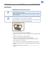
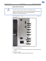
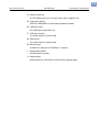
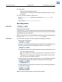
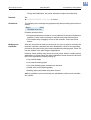
05/10 Version 5.05-00
USER MANUAL
AP5.4 – AP5.6
Commissioning and Operation
Installation ..................................................... 2
Unpacking and setting up the printer ........ 2
Checking the shipment .............................. 3
Product description ....................................... 5
Operating controls on
AP 5.4/5.6 “basic” and “peripheral” ............ 5
Operating controls on
AP 5.4/5.6 dispenser ................................. 7
Functionality of AP 5.4/5.6 dispenser ........ 9
Ports and connections ............................. 10
Warning signs on printer ......................... 12
Operation panel ....................................... 13
Operating modes ..................................... 14
Main operating steps ...................................16
Connecting the printer .............................16
Configuring the data interface ..................17
(De)activating the internal rewinder .........17
(De)activating the dispensing edge .........19
Setting the dispenser ...............................19
Operating in offline mode .........................20
Online operation ......................................21
Creating a print job ..................................22
Transferring a print job .............................23
Using SD cards ........................................25
Setting the real-time clock .......................26
2
05/10 Version 5.05-00
USER MANUAL
Commissioning and Operation
AP5.4 – AP5.6
Installation
Unpacking and setting up the printer
WARNING!
Lethal hazard from mains power!
« Only use the device in enclosed rooms under normal ambient conditions
(office atmosphere)!
CAUTION!
To avoid damage to the printer, observe the following:
« Do not lift the printer using the plastic components on the front and rear.
« To lift the printer, do not reach below the front hood.
[1]
AP 5.4 in the original packaging.
1. Remove all loose objects from the shipping box.
2. Carefully lift the printer out of the box together with the styrofoam packaging.
¯ Have a second person hold the box tightly.
3. Remove the styrofoam and plastic film from the printer.
¯ Store the original packaging for possible shipping at a later date!
4. Place the printer on a flat surface.
¯ To carry the printer, reach below the baseplate at the front and rear.
5. Open the front cover. Remove the styrofoam shipping lock from the printhead.
6. Check that the shipment is complete, see Checking the shipment on
page 3.
3
05/10 Version 5.05-00
USER MANUAL
Commissioning and Operation
AP5.4 – AP5.6
Checking the shipment
AP 5.4/5.6 “basic”
Delivery:
AP 5.4/5.6 “peripheral”
• Printer AP 5.4/5.6 including 2 pairs of core adapters [2B] and one paper
core [2A] for rewinding thermotransfer ribbon.
• Mains power cable
• Documentation CD
Contains detailed operating manual for printer as well as Windows drivers
and Servicing manual.
• Short operating manual (multilingual)
• Torx screwdriver [2C] size 10 (fastened to baseplate using adhesive tape)
• Support hooks [2D] for optional cutter (fastened to baseplate using adhesive tape)
B
A
C
E
[2]
AP 5.6 “peripheral” in delivered state.
D
4
05/10 Version 5.05-00
USER MANUAL
Commissioning and Operation
AP5.4 – AP5.6
AP 5.4/5.6 “peripheral” If you have ordered a AP 5.4/5.6 “peripheral” printer with an optional cutter [3],
with cutter
the cutter will be provided in a special carrier at the top of the box.
[3]
The cutter, if ordered, can be found in a special carrier at the top of the printer box.
For instructions on how to assemble the cutter, see Manual Cutter 2000 ,
“Fastening, Setting Up, Servicing”.
¯ The support hook needed to assemble the cutter is taped to the printer
baseplate.
AP 5.4/5.6
If you have ordered a AP 5.4/5.6 “basic” or “peripheral” dispenser, the follow“basic” dispenser,
ing parts are delivered separately:
AP 5.4/5.6
• Housing front part, bottom side with screw [4A]
“peripheral” dispenser
• Flange cover with screws [4B]
• Baffle plate [4C]
The baffle plate can be installed instead of the dispensing edge. With this
option, the printer is able to internally wind up the printed material.
¯ We recommend installing all of the housing parts when the printer is to be
used in the standard way without dispensing or rewinding functionality.
B
A
C
[4]
Components delivered separately with the AP 5.4/5.6 dispenser.
5
05/10 Version 5.05-00
USER MANUAL
Commissioning and Operation
AP5.4 – AP5.6
Product description
Operating controls on AP 5.4/5.6 “basic” and “peripheral”
C
A
B
[5]
Outside view of AP 5.4/5.6 “peripheral”.
A Control panel
LCD screen; 4 buttons; displays operating status of printer; allows parameter menu settings.
B Connection for additional devices:
(Only to AP 5.4/5.6 “peripheral”). This is where the optional cutter or rewinder (AP 5.4 only) is connected.
C Front cover:
Open this to insert material and the ribbon.
6
05/10 Version 5.05-00
USER MANUAL
Commissioning and Operation
AP5.4 – AP5.6
A
E
B
F
G
C
D
H
[6]
Operating controls of AP 5.4/5.6.
A Ribbon unwinding mandrel:
Holds the new ribbon roll
B Ribbon winding mandrel
Holds the cardboard core that rewinds the spent ribbon.
C Connection flange for additional devices
You can fasten either a cutter or rewinder (AP 5.4 only) here. To do this,
you first have to remove the plastic cover.
D Pressure lever
Opening the pressure lever lifts the printhead. You do this to insert material/ribbon or to clean the printhead/print roller.
E Material unwinder
This is where you install the roll with the label material.
F Material strain relief
Allows the label material to unroll evenly.
G Guiding disk
Prevents material roll from sliding out sideways.
H Adapter rings
For adapting unwinder to core diameter of material roll.
7
05/10 Version 5.05-00
USER MANUAL
Commissioning and Operation
AP5.4 – AP5.6
Operating controls on AP 5.4/5.6 dispenser
AP 5.4/5.6 “basic” or
“peripheral” dispenser
A
B
C
D
F
E
[7]
Additional operating controls on AP 5.4/5.6 dispenser.
A Dispensing edge:
This is where the labels are separated from the backing paper.
B Plugs:
Connector for dispensing edge sensor.
C Dispensing roll:
This holds the material ribbon taut over the dispensing edge.
D Button for dispensing roll:
Press the red button to remove the dispensing roll.
E Deflecting shaft:
This deflects the backing paper.
F Rewinder:
This rewinds the backing paper.
8
05/10 Version 5.05-00
USER MANUAL
Commissioning and Operation
AP5.4 – AP5.6
AP 5.4/5.6 “basic” or
“peripheral” dispenser
in rewinder mode
A
C
B
[8]
Additional operating controls of AP 5.4/5.6 dispenser in rewinding mode.
A Baffle plate:
Deflects the printed labels without dispensing any of them.
B Deflecting shaft:
This deflects the labels.
C Rewinder
Rewinds the label web.
9
05/10 Version 5.05-00
USER MANUAL
Commissioning and Operation
AP5.4 – AP5.6
Functionality of AP 5.4/5.6 dispenser
The AP 5.4/5.6 dispenser allows freshly printed labels to be dispensed (via the
dispensing edge) or rewound in the printer enclosure (via the defelector).
• When used as a dispenser, the label material is drawn around the dispensing edge and only the backing paper is rewound.
• When used as a rewinder, the printed label is guided across a baffle plate
and rewound together with the backing paper.
The electronic components in the rewinder control the tensile force on the release paper so that the same force is applied for all winding diameters. This is
controlled independently of the material width and printing speed. The controller can be set automatically or manually depending on the settings in the parameter menu.
¯ The manual setting is only necessary in special cases and may only be performed by qualified, authorised service personnel.
After switching on the printer, the rewinder is initialised and the backing paper
is tightened.
Once a print job is received, the printer searches for the first label start marking
at reduced printing speed. To do this, the label material is moved by at least
the distance between the label sensor and the printhead (70 mm). This distance is used by the rewinder controller to calculate the diameter of the previously wound backing paper. To allow the controller to calculate the diameter
even with endless material, in this case printing also does not start until the
material has moved 70 mm. The print job is carried out at the speed that has
been set in the parameter menu or as specified by the print job.
If a fault occurs during operation, the rewinder shuts off automatically.
Once the maximum diameter of the backing paper has been reached, a message appears on the display and the rewinder shuts off automatically.
Dispenser operating
modes
The following operating modes are available for the dispenser:
• Dispenser mode with dispenser sensor:
The material feed ends at the dispensing edge, i.e., the label to be dispensed remains hanging on the dispensing edge (set dispensing position).
The printer waits until the label is removed before moving the next empty
label beneath the printhead and then printing and dispensing it.
• Dispenser mode with foot switch:
Pressing the foot switch releases the label for printing and dispensing. Afterwards, the next empty label is positioned beneath the printhead.
See (De)activating the dispensing edge auf Seite 19.
10
05/10 Version 5.05-00
USER MANUAL
Commissioning and Operation
AP5.4 – AP5.6
Ports and connections
CAUTION!
Using poor quality auxiliary equipment can damage the printer.
« Only connect the printer to devices that fulfil the SELV (safety extra-low
voltage) circuit requirements in accordance with EN 60950.
« Only connect original accessories.
For instructions on how to use the network connections, see topic section “Advanced Applications”, chapter Data Transmission with Ethernet on page 18.
A
B
C
D
E
F
G
I
H
J
[9]
The rear side of the AP 5.4/5.6 with I/O board (option) installed.
A Start/stop signal input
Connections for a foot switch (signal starts printer) or stacker (signal stops
printer)
B Signal port (option)
4 inputs / 3 outputs on optionally available I/O board
11
05/10 Version 5.05-00
USER MANUAL
Commissioning and Operation
AP5.4 – AP5.6
C Memory card slot
For SD cards where you can store fonts, logos, graphics, etc.
D Serial port (option):
RS232 or RS422/485 on optionally available I/O board
E USB port (host)
For USB sticks, keyboards, etc.
F USB port (device)
For serial transfer of printer data.
G RS232 port
For serial transfer of printer data.
H Ethernet port
Interface for “Ethernet 10/100 Base T” network
I
Mains power switch
On/Off switch for printer
J Mains socket
Mains socket for connection to mains using supplied cable.
12
05/10 Version 5.05-00
USER MANUAL
Commissioning and Operation
AP5.4 – AP5.6
Warning signs on printer
WARNING!
If warning signs are missing on the printer, possible hazards may not be noticed in time.
« Do not remove warning stickers.
« Replace any warning stickers if they become lost or illegible.
! WARNING
A
Pinch point.
Keep hands clear
of rollers.
A5346
B
[10] Warning signs on AP 5.4/5.6.
The warning sign [10A] warns users about the pinching hazard on moving
parts of the printer (part no. A5346).
The warning sign [10B] warns users about the hazard of getting hands or
fingers burned at hot surfaces close to the printhead (part no. A5640).
13
05/10 Version 5.05-00
USER MANUAL
Commissioning and Operation
AP5.4 – AP5.6
Operation panel
A
B
C
D
E
[11] Operation panel of AP 5.4/5.6.
A Display
The display contains two rows of 32 digits for displaying operating modes,
parameters, values, statuses and messages. Users can adjust the display
language so that the text appears in their native language. The backlighting ensures that the screen is easily legible.
B Cut button
– Offline: Starts a cut (prerequisite: cutter is installed and activated)
– Parameters menu: navigates to deeper menu levels or selects menu
options.
– Parameters menu: Decreases values
C Online button
– Switches between online and offline mode.
– Confirms entries, menu options or status messages.
– Selects print job and enters field data for printer in standalone mode.
D Feed button
– Offline: Starts material feed
– Online: Starts printing process after it has been paused
– Parameters menu: Navigates to higher menu levels or selects menu
options.
– Parameters menu: Increases values.
14
05/10 Version 5.05-00
USER MANUAL
Commissioning and Operation
AP5.4 – AP5.6
E Prog button
– Offline: Opens Parameters menu
– Parameter menu: Moves back one step in Parameters menu or quits
the menu.
For more functions and more details, see
• section Offline mode auf Seite 14 and section Online mode auf
Seite 14
• topic section InfoPrintouts and Parameters Operating modes
Offline mode
OFFLINE
0 JOBS
No print jobs are queued.
In Offline mode, you can change the printer settings. This operating mode is
normally active when the printer is first turned on. Print jobs are received at the
selected port but not processed.
¯ To set the printer so that it immediately switches to online mode after being
turned on, set SYSTEM PARAMETER > Turn-on mode to “Online”.
Online mode
In Online mode, printjobs are received and immediately processed.
• No print jobs are queued.
ONLINE
0 JOBS
• If data is currently being transferred to the printer, this is indicated by a single dot to the lower right of the displayed number of current jobs.
ONLINE
0: JOBS
An additional dot at mid-line height indicates when the interpreter is active.
– No dot: no data to interpret.
– Dot: The interpreter is currently running (there is still data in the spooler)
– Flashing dot: The interpreter is waiting for more data in order to complete a command (no data in spooler).
• During printing, the number of jobs in process (13) are displayed as well as
the remaining quantity (25) of labels to be printed in the current job.
ONLINE 13 JOBS
Restcount: 25
• If a print job has been specified as continuous, the remaining quantity for
this job will be endless.
ONLINE 13 JOBS
Restcount: endless
¯ To stop the printing process, press the Online button.
15
05/10 Version 5.05-00
USER MANUAL
Commissioning and Operation
AP5.4 – AP5.6
Message mode
Status messages are used to indicate errors or certain operating statuses.
When status messages appear, the background colour of the display becomes
red. When a status message is present, the printer waits until the error has
been eliminated and/or acknowledged. When the error is acknowledged, the
printer switches from message mode to offline mode (depending on the error
and state of previous process).
Status messages consist of the status number together with a brief description:
Status
5001
No punch detected
For instance, status message 5001 (see above) appears when the printer is
configured for punched label material but continuous material (unpunched) is
inserted. In this case, the printer continues to transport the material for a few
more seconds until the error message appears.
For more on the status messages as well as a detailed list of all status messages, see Status Reports .
Standalone mode
In standalone mode (operation without data connection to computer), print
jobs are not transferred via data cable but are instead stored on a SD card.
From there, you can access them from the control panel or using a connected
keyboard.
For more information on standalone mode, see topic section “Advanced Applications”, chapter Standalone Operation on page 9.
16
05/10 Version 5.05-00
USER MANUAL
Commissioning and Operation
AP5.4 – AP5.6
Main operating steps
Connecting the printer
WARNING!
This unit operates at mains voltage! Contacting electrically live components
can cause potentially lethal electrical shocks and burns.
« Make sure that the machine has been switched off before connecting the
mains cable.
« Only operate the printer at the mains voltage given on the type plate.
« Only connect the printer to a properly installed mains socket with protective earth.
« When installing the mains cable, ensure the following:
a) Nobody can stumble over the cable
b) Mains plug can be pulled in case of emergency
C
B
A
[12] Rear side of AP 5.6.
1. Make sure that the printer is switched off (mains switch [12C] at “0” position).
2. Connect the mains cable [12A] to the mains connector at the printer.
3. Connect the mains cable into a mains socket.
4. Connect the printer and computer or printer and network using suitable
data cable (example: USB cable to USB (device) port [12B] of printer and
to USB port of host computers).
5. Turn on the unit using the mains power switch (position “1”).
As soon as the printer is ready, the following appears:
OFFLINE
0 JOBS
¯ If SYSTEM PARAMETERS > Turn-on mode is set to “Online”, the printer
switches directly into online mode after turning on the printer!
17
05/10 Version 5.05-00
USER MANUAL
Commissioning and Operation
AP5.4 – AP5.6
Configuring the data interface
The AP 5.4/5.6 has been pre-configured at our factory for data transmission
through the USB port. Alternatively, printer data can also be transmitted via
RS232, RS422/485 (only with optional I/O board), USB or Ethernet port.
« Choosing the port: INTERFACE PARA > EASYPLUGINTERPR > Interface
« Configuring the port:
• RS232 (COM1): INTERFACE PARA > COM1 PORT > …
• RS232/422/485 (COM3): INTERFACE PARA > COM3 PORT > …
• Ethernet: INTERFACE PARA > NETWORK PARAM. > …
¯ We recommend that your network administrator configures the network
settings.
• USB: no configuration required
For more information on how to set the parameters, see topic section “Info
Printouts and Parameters”, Operating the Parameter Menu .
The order numbers for network and data cables are given in topic section
Accessories .
For more information on how to use the Ethernet port, see topic section
“Advanced Applications”, chapter Data Transmission with Ethernet on
page 18.
(De)activating the internal rewinder
¯ Only applies to AP 5.4/5.6 dispensers with baffle plate installed.
Activate
¯ Ensure that material has been inserted before you activate the rewinding
function, otherwise a fault message will appear!
For information on inserting material, see topic section “Setup”, chapter
Inserting Label Material on page 6.
Set
1. SYSTEM PARAMETER > Periph. device to “Intern Rewinder”.
¯ Do not confuse this with “Rewinder” because this setting activates the
external rewinder (additional device)!
After being activated, the system checks the direction of rotation of the rewinder.
Rewinder direct.
Facing outside
“Facing outside” is set by default.
2. If required, press the cut/feed button to change the direction of rotation.
3. Press the ENTER button to confirm your selection.
The printer restarts. Afterwards, an additional menu REWINDER PARA can
be opened from the main menu, and this contains the Rewind direction parameter. Using this parameter, you can change the direction of rotation.
18
05/10 Version 5.05-00
USER MANUAL
Commissioning and Operation
AP5.4 – AP5.6
During the initialisation, the printer attempts to tighten the label strip.
Deactivate
Set
« SYSTEM PARAMETER > Perip. device to “None”.
Possible fault
The following error message may appear briefly after activating the internal rewinder:
Status
5004
Rewinder mat. tear
Possible causes include:
• No material has been inserted or end of material has not been fastened to
rewinder. Fasten end of material to rewinder and press Online button.
• The material strip is sagging in front of the rewinder. Press the Online
button.
Modifying main
initialisation
After this, the printer is ready for the first job. As soon as a job is received, the
rewinder controller calculates the main initialisation values for the rewinding
process on the basis of the given material width and printing speed. These values are suitable for a wide range of applications.
However, these settings may cause too much printer offset in certain special
applications. In these cases, the main initialisation values will have to be modified. Such applications include printing on:
• Very narrow labels
• Very coarse backing paper
• Very thick backing paper compared to the label
• Labels stuck on the backing paper
• Backing paper perforated along label contour
¯ Only qualified service technicians are permitted to edit the main initialisation values!
19
05/10 Version 5.05-00
USER MANUAL
Commissioning and Operation
AP5.4 – AP5.6
(De)activating the dispensing edge
¯ Only applies to AP 5.4/5.6 dispensers with dispensing edge installed!
Activating
Set
« SYSTEM PARAMETER > Periph. device to “Dispenser”.
The printer restarts. Afterwards, an additional menu DISPENSER PARA can be
accessed that contains all of the parameters required for dispensing mode:
Parameters
Possible settings
Dispenser mode
True 1:1 mode (default), Batch mode, Normal 1:1 mode
Dispensing position
Configurable in millimetres (default: 0.0 mm)
Display mode
Remaining qty. in job (default), dispenser counter
Dispense counter
Quantity presetting (default = 0)
Application mode
Safe mode (default), immediate mode
Start source
Foot switch, light sensor (default)
[Tab. 1] Parameters in DISPENSER PARA menu.
For more on the listed parameters, see Info Printouts and Parameters .
Deactivating
Set
« SYSTEM PARAMETER > Periph. device to “None”.
Setting the dispenser
Application A
The label should be dispensed to that a narrow strip still sticks to the backing
paper above the dispensing edge. After manually removing the dispensed label, the next label is printed and dispensed.
Set
« DISPENSER PARA > Dispenseposition to -6.0 mm (for strong adhesives, this may
have to be reduced to -8.0 mm).
Set
« DISPENSER PARA > Start source to “Light barrier”.
Application B
The label should be printed and dispensed after receiving a signal from the
connected foot switch.
Set
« SYSTEM PARAMETER > External signal to “Singlestart”.
Set
« DISPENSER PARA > Dispenseposition to -6.0 mm (for strong adhesives, this may
have to be reduced to -8.0 mm).
Set
« DISPENSER PARA > Start source to “Foot switch”.
20
05/10 Version 5.05-00
USER MANUAL
Commissioning and Operation
AP5.4 – AP5.6
Label length
< 40 mm
¯ If very short labels are to be printed (PRINT PARAMETERS > Material length is
set to < 40 mm), the printer is automatically initialised for the material before
printing.
For more information, see the parameter description DISPENSER PARA >
Calibration mode under Info Printouts and Parameters .
Operating in offline mode
• Changing from offline to online mode:
OFFLINE
x JOBS
ONLINE
Online
x JOBS
• Switching into online mode when print job is stopped
OFFLINE
Stopped
x JOBS
xx
ONLINE
Stopped
Online
x JOBS
xx
• Slow material and ribbon feed:
OFFLINE
x JOBS
OFFLINE x JOBS
feeding...
Online Feed
• Material is reversing below the printhead:
OFFLINE
x JOBS
Cut
Online
OFFLINE x JOBS
feeding...
x JOBS
Cut
Online Feed
• Reset
OFFLINE
OFFLINE
x JOBS
• Opening the parameter menu
OFFLINE
x JOBS
Prog
PRINT INFO
• Feeding material to next punch or while button is pressed:
OFFLINE
x JOBS
Feed
OFFLINE x JOBS
feeding...
• Setting the label length automatically:
OFFLINE
x JOBS
Feed Prog
OFFLINE x JOBS
Man Calibrate
For more information, see topic section “Setup”, chapter Setting the label
length automatically .
21
05/10 Version 5.05-00
USER MANUAL
Commissioning and Operation
AP5.4 – AP5.6
Online operation
• Switching to offline mode:
ONLINE
x JOBS
OFFLINE
Online
x JOBS
• Adjusting the print contrast: press Feed button to increase, press Cut button to decrease the print contrast
ONLINE
x JOBS
Prog
Print contrast
xxx%
• Stopping a print job: The label currently being printed will be completed before the printer stops.
ONLINE X JOBS
Restcount
XXX
Prog
ONLINE
Stopped
X JOBS
XXX a
OFFLINE
x JOBS
a) The message “Stopped xxx” alternates with “Press Feed”.
• Switching to offline mode when print job is stopped
ONLINE X JOBS
Stopped
XXX
Online
• Continuing a print job
ONLINE X JOBS
Stopped
XXX
ONLINE X JOBS
Restcount
XXX
Feed
• Standalone mode: select a print job stored on an SD card (example:
Testdat.FOR)
ONLINE
x JOBS
Online
Prog
Select a file
Testdat.FOR
For more information, see topic section “Advanced Applications”, chapter
Standalone Operation on page 9.
22
05/10 Version 5.05-00
USER MANUAL
Commissioning and Operation
AP5.4 – AP5.6
Creating a print job
There are basically two ways of generating a print job: You can use a label layout program together with a Windows printer driver or create a simple text file
containing printer commands.
Windows printer driver There are different printer drivers available for the various versions of Windows. Using the printer drivers, you can print from nearly any Windows application. The functionality depends heavily on the layout software you use. We
recommend using a special label layout program such as NiceLabel (test version included on Documentation CD, see Layout program on page 22).
Printer drivers can be found here:
• Internet: Avery Dennison • Documentation CD (also contains this operating manual)
Installing the printer driver:
1. Insert the documentation CD
The language selection menu [13] opens.
2. Depending on the version of Windows in use, click the upper [13A] or lower
[13B] line.
¯ Drivers for older versions of Windows (see lower line [13B]) are only
available for AP 5.4.
3. Follow the instructions given by the Installation Wizard.
C
A
B
[13] The language selection menu appears after you insert the Documentation CD.
Layout program
The Documentation CD contains a test version of the “NiceLabel” layout program.
Installing:
1. Insert the Documentation CD
2. Click “Printer drivers and label software” [13C].
3. Follow the instructions given by the Installation Wizard.
23
05/10 Version 5.05-00
USER MANUAL
Commissioning and Operation
AP5.4 – AP5.6
Command file
Enter a sequence of printer commands into a text file and send this file to the
printer. To do this, you require a simple text editor and the copy command in
MS-DOS. Easy-Plug is a special command language for formulating print jobs.
However, writing a print job in text file format does require some programming
knowledge. Furthermore, you will not be able to preview the resulting printout
on screen. Instead, you will have to create a test printout in order to view the
final results of your print job.
For a practical example of a print job together with instructions for testing purposes, see Easy-Plug Manual, topic section “General Notes, Definitions and
Command Overview”, section Programming Example .
Transferring a print job
The printer cannot process the print job until it has been loaded into RAM. This
can be accomplished in two ways:
• Using a data cable from the PC
• Using the card slot and a SD card
Data cable and layout
program
If you are using a label layout program, the appropriate print command has to
be triggered. The data port is set when you install the printer driver.
Data cable and
Easy Plug file
Requirements:
• Data cable has been connected between printer and PC or between printer
and network
• Command file was created (here: “testjob.txt”) and stored in computer or
on SD card
• The command line (DOS prompt) has been started in Windows
Enter the following command:
• Serial port (COM1): copy testjob.txt com1
• USB port: copy testjob.txt \\computer name\share
name, with
– Computer name = name of computer. In Windows XP for instance, this
can be found under START > SETTINGS > CONTROL PANEL > SYSTEM > COMPUTER NAME
– In Windows XP, the share name can be found under START > SETTINGS > PRINTERS AND FAXES after right-clicking PROPERTIES >
SHARE. The share name is a printer connected to a specific port, such
as the USB port for USB transfer or the TCP/IP port for Ethernet transfer.
• Ethernet port: as described above for the USB port. For more information
on transmitting data via Ethernet, see topic section “Advanced Applications”, chapter Data Transmission with Ethernet on page 18.
24
05/10 Version 5.05-00
USER MANUAL
Commissioning and Operation
AP5.4 – AP5.6
Tips on transferring data via USB or Ethernet:
¯ The procedure described here does not apply to Windows 98,
Windows ME or Windows NT 4.0.
¯ The share name must comply with MS-DOS conventions (max. 8 characters long, no special characters or spaces)
SD card and
Easy-Plug file
Printing starts immediately after switching on
1. Rename print job file on SD card (root directory) as autostrt.for.
2. Insert SD card into card slot on printer (see next section).
3. Switch on printer.
The printer processes the print job as soon as it is in online mode.
Alternatively, the print job can be started in standalone mode; for more details,
see topic section “Advanced Applications”, Standalone Operation on
page 9.
25
05/10 Version 5.05-00
USER MANUAL
Commissioning and Operation
AP5.4 – AP5.6
Using SD cards
CAUTION!
To prevent malfunctions, observe the following.
« Only use SD cards that have been approved by the manufacturer.
« Only insert or remove SD cards after the printer has been switched off.
« After switching off, do not remove the SD cards until the backlighting on the
screen has gone out.
Recommended card type:
Xmore industrial 2 GB (item no. A101465) [14]
[14] Recommended SD card.
Inserting the SD card:
1. Switch off the printer.
2. Insert the SD card into the card slot as shown [15].
¯ The contacts point to the front left side.
¯ Once the card is inserted two-thirds of the way [15A], a mechanical resistance becomes apparent. Apply a little more force to overcome the resistance, insert the card until it stops and then release it. The card springs
back a little ways towards its final resting position [15B].
A
B
A
[15] Insert the SD card.
26
05/10 Version 5.05-00
USER MANUAL
Commissioning and Operation
AP5.4 – AP5.6
Removing the card:
1. Insert the card into the slot until it stops [15B] and release it.
The card springs back out of the card slot [15A].
2. Remove the card fully from the slot.
For more on using memory cards, refer to the Plug-in Card Manual, topic section “Application”, chapter CF/SD Cards .
Setting the real-time clock
The real-time clock of the AP 5.4/5.6 can be used, for example, to calculate
and print the expiry date of a perishable product.
Setting the real-time clock:
1. Choose SYSTEM PARAMETERS > Realtime clock.
Realtime clock
dd.mm.yyyy hh:mm
dd=day, mm=month, yyyy=year, hh=hour,
mm=minute
2. Enter the date and time:
– Cut button: moves the cursor
– Feed button: modified the setting
– Online button: stores the setting