1
Previous Menu
‘-- ““-
VISTA
SERIES
,-.
4140XMP
lNSTALLATlON
INSTRUCTIONS
,-.
N~-lVl
1/92
CONGRATUMTIONS
on yow pmchase of the WSTA 4140~!
w
The purpose of these @tiation
Instructions is to give you a brief overview of
the ~STA 4140~
system, and provide instructions for installing a basic
system.
As always, ADEMCO is there for YOU! Our S~ES
and TECHNICfi
SWPORT stiff are eager to assist you in any way they can, so don’t hesitate
to d, for any reason!
East Coast Technical Suppoti: 1-800-645-7492(8 a.m,-6p.m. E.S.T.)
West Coast Technical Suppoti: 1-800-458-9469(8 a.m. -5p.m. P. S.T.)
PME,
Before you call Technical Support, be sure you
●
Check all wiring connections.
Dekrmine that the power supply antior backup battery are supplying
proper voltages.
●
Ve@
●
your programming information where applicable.
c Note the proper model number of this product, and the version level (if
known) along with any documentation that came with the product.
Note your Ademco customer number andor company name.
Having this information handy will make it easier for us to serve you
quic~y and effectively.
●
Again, CONGRA~TIONS,
-2-
and ~WOME
~OARD!
“
—.
GENERAL
INFORMATION
.... ... ... .. ... ... .
The VI“ISTA tintml ...... .................... ..............~
E-y P~ramming
.......... ............. ............ .. ..s
4140XMP Enhancemef nets.............................. 5
Note to 4140XKM users ................................... 5
Il.
ZONE
CONFIGURATIONS
. . . . . . . . . . . . . . . . ...6
Z~ETYPE
DEFIN~s
....... ..................... .. .. 6
SASfC9 HARD-WRED ZONES .. ........................ 6
Zone l ........................................................ 6
Zone 9 ........................................................ 6
tin2-8 ..... ............. .. ....... ......... .. ......... .. .. 6
2-WIRE POLLING L~P
(MuMplex ha) ............. 7
Wire Run Lenmk ................ ..... ........... .. ..... .. 7
Advisories .. ..................................... ... ........ 7
WIRELESS EXPANSION .................................. 8
4280t428Ga
RF Rernkem ............... .. ............ a
Programming Notes tir Wirele~ Devbs ....... .. . a
SupewisiOn ......... .... ..... ............................... a
House .ldentitication ...................................... a
Transmmer fdantfmtion ..... ... ...... ..... ............ 8
Sniffer We to Wtemine Housa ID .... ............. a
Snfler Mde to CheA Trtismittem
................. a
GOINO Go Test Mode ...................... ................ a
Im@nant Sattery Notim ................................ 9
Wireless Zone Types ..................................... 9
Advi=ties ...... .. ... ........ ............................. ..g
,.=. .
Ill.
-..
Iv.
___
TABLE OF
“ “- CONTENTS
v. SYSTEM
1.
PERIPHERAL
DEVICES . . . .. .. . . . . . . . .. . ....1 O
REWTE ~NSOLES ...... ................ ... ............10
4127 fixti
Wod Console ..............................l0
4137 Deluxe Fixti wrd Console ....................l 0
5137 Alpha Custom LCD Conmle...- ...............l O
tinsole
Wring ............................................lO
~RNALSOUND~
.............. ........ .. .. ... .....lO
Relw O~ti
......... ..... ........... .... ... ..............lO
Non-UL Insalldbns ....... ... ..........................lo
UL installations ...........................................lo
SMOKE DETECTORS ......................................1 1
Zone 1... ... . ................................................
~ne
24 ....... ..... ......... .. .. ................. ..... ...j!
timpatible
Smoke Detetiom .........................l 1
Polling Lwp Smoke Dettim
......... ........ .. ....ll
Advi%ties ................. .. .. .................. .. ..... ...ll
PASSIVE INFRARED DETECTORS ........ ...... ......11
Polflng kop PIR (4275) ................... .. ... .. ......1 1
Polli~ L*P PIR (4186/427a) .........................l 1
Wirele= PIR (5776) .. .. ........... ................ ... ...1 1
GLAsS SREAK Detectors
............................1 1
PHONE LINE CONNECnONS ....... ......... ... .. ... ...l2
coNNEcmw7RffiER
ouTpLr73 ... ... ... .. .....l2
General information .. .............. ................ .....l2
Ground Stan Nule
..... .. ... ..........................l2
Remote Keyswfich (4148) ....... ...... ... .. ....... ....13
MOUNTING
& POWERING . . . . . . . . . . . . . . . ...14
wmNG
...... .. .. ......... .. ... ................. ....... ...l4
Wuming the4140XMP PC Sod .. ... .. .. ... .......14
Mounting the 4140XMP Ld ....... .. ... ..... .. ... ...l4
hunting the 4127 C
Sudaa MountiW the 4137E137 tinsoles .......l 5
Flush Mountiw with Trim Ring Kt (5137TRw .. ...1s
Adiusting the Alpha tinsola Mewing Angia .......l 5
PowERING THEsYsTEM .............. .. ...............l6
Prima~POwer ..................... .. ............. ..... ...la
Sa*-Up POwer.. ....... .................. ...... .. ........l6
Satte~
Standby Table ..................................l6
Eanh Ground tinnembns
... ... ...... ... .. ...........l6
Power-Up Pmmdure . .... ... .. .............. .. .. .. ......l6
PolliW LMP Cunent Draw Worksheet .... .. ........16
Auxifiaw Device Cumenl Draw Woksheet .........l 6
OPERATION . . . . . . . . . . . . . . . . . . . . . . 17
SECURfTY AwESSCODES ... .. ............ ...........l7
Maser Code ... ......... ........ ... .. .... ..... ............17
Dures Ne ..................... .. .... ... ............. ...l7
Tem~ra~
bales ........................................l7
S*ysMer
tide
(User 22) ............................. 17
K5YPwwNCmS,
... .. ... .. ..... .. .. ..... ............l8
General information .....................................l8
VieMWhnhdd
h~ages
.....................la
Using the Suift.in Users Gutie .......................18
Dispbying Descriptors ........ ....... ..................la
Pank Keys ....... .. ..... .. ................................l8
TROUSLE COND~lONS ..................................l9
.Check. Message ........................................l9
Pwer Fdlure ...... ............. ..... .. .. .............. ...lg
Other TmuNe~nditions
....... ............... .. ......l9
~CALLING ALARM& TROUBLE MESSAGES ..... 19
S~lNG
THE REAL-nME CLOCK . .. .. ...............19
V1.
SYSTEM
COMMUNICATIONS
. . . . .. .. . .. . ..2O
Split/Dual ReWtiing .....................................2o
Adew
LOw SW
.. ............................. ......20
SESCOAtRadionics .....................................2O
&2
ReWfling .............................................2O
*2 ~press ....... ... .... .. ..... .. .... ... .. ..............20
Ademm High SWed Reponing .......................2o
tintaa
ID Re@iW .. .............. .. .. ... .. ..........2o
Table of tintaa
ID Event @ales, ...................2l
4140xMP timmunbtbn
P~ramming
Gutie. .21
V1l.
PROGRAMMING
THE SYSTEM . . . . . . . . . ...22
GENERAL PRffiRAMMING PROCEDURES ........22
Defauk Prqrammim
. ... ..... .. .. .. ............ ........22
Data Pmg~amming .......................................2
Pmgmmming Steps, ....................................22
COMMUNICA~N
DEFAULT PR~WMING
....23
Easyto-PrWrm
timmuntitb”
Fietis ..........23
LOW Speed .................................................23
Ademrn fipress ......... ..... .. .................. ... ...23
Mm=
Hgh S~
. .................. .. ... .. ..........23
tint=
lD . ............ .. ................ ............. .....~
P-~Miffi
ZONE DESCRIPTORS .............24
Entering Zone De=btom
............. ..... ..........24
Adding Custom Words ..................................24
Creating a Custom Message ..........................25
V_la~
of Words In MemoV. . ........ ...... ....25
Vlll.
00WNLOAOING
PRIMER* . . . . . . . . . . . . . ...26
lx.
TESTING THE SYSTEM . . . . . . . . . . . . . . . . . ...27
Using Tes Me .. ............................. ..........27
Am4 System Test . ..... ... .................... ........27
Turning the SyMem @er to the User ...............27
Note TO The lnstallar ....................................27
x.
TROUBLESHOOTING’
. . . . . . . . . . . . . . . . . . . ...28
~NSOES
......... ... ............... .. .. ....... ............28
HARD-WIRED ZONES 14 .......................... ......26
RPMs .................... .. ... ........................ .........2a
WIRELESS .... .. ........... ................ .. .. ..............29
~MMUNICAn~S
...... .. ... .... .. ... .............. .....3O
xl.
X11.
-—
-—
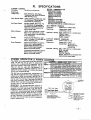
SPECIFICATIONS
4190WH
DIP
SWITCH
PROGRAMMING
*
. . . . . . . . . . . . . . . . . . . . . . . . ...31
OPERATION
SETTING
&
WIRING .... ......31
TAsLES
.... .......33
FORM . . . . . . . . . . . . . . . . . . ...36
This i=ua has a revised format a“d incl.des
thenewsedions
indicated byastetisks.
Mamin fines indicate other principal chanqes.
-3-
LIST OF FIGURES
1.
4140XMP
SYSTEM
LOOP DEVICES
2.
POLLING
3.
4280/4280-8
....... .............. .. ...... .. .. ... .. .... . . . ...... .. ........... .......... .. ........ .... ................. ..5
........ ............ .. ........ ........ ... . .. .... ................... .. .......... .. ............. ..7
RF RECEIVER
... .... ............................ ....... ....... ........... .... ...............................8
4.
CONNECTOR
5.
GROUND
6.
REMOTE KEYSWCH
?.
MOUNTING
THE
PC BOARD ................................. .. ....... ....... ............................................l 4
8.
MOUNTING
THE
CABINET
9.
SURFACE
10.
FLUSH MOUNTING
J7 ... ......... ..................... ................. ......... ......... ........................ ......... .........l 2
START
MODULE
MOUNTING
11.
ADJUSTING
12.
4180WH
13.
SUMMARY
. .............................. .. ..................................................... ........ I 2
WRING
.. .. .. ...... .......... .... .. ..... .... .. .. .. .... .. ......... ........ .... .......... .. .. ... ..l 3
LOCK ............ ............................................. .............................14
THE CONSOLES
THE CONSOLES
. .................. .... .. .................. . .. ....... .......... ...........1 5
.... ............ ...... .. ........................... ......... .......... .. .. .....l 5
THE VIEW ANGLHINSERTING
OPERAnON
THE NAMEPUTE
& WIRING DIAGM
OF CONNECTIONS
stvtN
DIAGRAM
fltps
..........................................l 5
.............. .. .. .... .................................. ...............3l
.........................................................................32
TO
t~sy
mLLATION
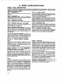
The following steps are reauired to Drooerlv
install a VISTA XMP system:
!..
STEP
1
Become fami~ir wkh the system by readng the GENERAL
determina the hardware reauired for the installation.
STEP
2
Determine the aysfem’a zone cotigurefion
and wiring requirements
by reviewing section
11:ZONE CONFIGURATIONS
and sedbn
Ill: PERIPHERAL
DEVICES. ff the inetallatnn
is
UL rated, che~ the special UL requirements
included in aati escfion.
STEP
3
Orwe tha wiring is mmpleted,
mount the Control
the inetmctiirra
provided in seamn IV MOUNTING
STEP
4
Learn how the ayatem operatea,
Conditions
and how to set the
OPERATION.
STEP
5
V the ayatem is to be euwrvised
by a central monitoring efa~wn, read section Vl: SYSTEM
COMMUNICATIONS
and aecfiin Vll: PROGRAMMING
THE SYST~,
COMMUNICATION
DEFAULT
PROGRAMMING
for descriptions
of reporting
tormate
and a list of
@M~ntition
programming
defauft valuea.
STEP
6
Program the system via the keypad or by downloading
from a remote bcafwn,
following
the instructions
in section
Vil: PROGRAMMING
THE SYSTEM
and ae~ion
VIII:
DOWNLOADING
PRIMER (K sppl~le).
STEP
7
Teat fhe system and teach the
procedures in sedlon IX: TESTING
ff problems
ADVISORIES
MODEL
-4-
.
NUMBERS
ar,
including
real-time
INFORMATION
aecrion
and
and make power connections
Iollowing
& POWERING THE SYSTEM.
security codes, keypad tutilons,
trouble
clock, by reading
se~ion
V: SYSTEM
user how to perform
WE SYSTEM.
all commanda,
following
the
refer to section X: TROUBLESHOOTING.
Throughoti
this manual, information
that requires special attention is highlighted
in the
ADVISORIES
paragraphs. This informatwn
includes system timitatwns, caveats and other
information
vital to the proper operation of the system. Be sure to read these paragraphs
carefully.
Unless othewise
products.
noted,
product
mdel
numhrs
listed in this manual
refer to Ademco
. ,,
1. GENERAL
z.
THE VISTA CONTROL
The vISTA 4140XMP bntrol
is a microprocessor basti
pm$rammable
system and Iaatures EEROM memo~
Iectlnology (power loss d~s
not msuft in the loss of
information). ~
@nml su~ns
up to 9 wired zones of
prottiion,
ex~titib
to W zones (wired and/or wireless)
using 2-wire polling
loop devices,
and/or wireless
tranmfiem
(5700 series).
EASY PROGRAMMING
programming
can ti
pdormed
al the office prior to
inStallatWn, or on the~b sita dtrtily
from the ~n~Ie,
Or
an b downbadd
fmm a remote ~Wn
or m the @b she
(using a PC -p
wkh 41oOSM Serial Modub) by mi~ the
Ademco 4130PC Downloading
SoWare.
For installer
rnnl!enbm,
the tinml
ispe.pmgrammed
wfih aset Of
stindard values fhti b des~nd to meat the neds of many
insta!llalbns. These values. however, ~ntichangdtosufi
ther!eds ofanypntikr
imtdktiin.
Theamml~nabo
ba pre~qmmmd
@ the instdkr wfih one of four Sandwd
Wmmunbtion
default p~ramming
values, eliminating the
need for efienske p~ramming
time and effofi.
NOTE TO 4140XM USERS: The following are some
dfierenrns bween tk 4140XMP & 4140XM @nels that will
affti your inslalbtiin
Drai~$
. Retis4, O*Y to folbw taminal bti
kyoti.
. AC power suppfiti by No. 1361 tmnslormer (unpolartid)
rated at 16.5VAC,,, AnuA
. One value (2k Q) k ufor dl EOLR su~wisd
zonas. I
. ~ne 1 o~rates ~ an EOLR supwkd
‘mne onfy.
. Revisal rating md wiriW method to tb mxifiaw triggers.
‘I
fom to a~mmdate
new f~tiures.
. Revised p~rammi~
I Use PC ~wnbad
*WO
tht woooti
lb 4140xMP.
I
. Real-time clti
must k set (usin~”5137 wnsole) bafore
-“
.,-- .
.
-.
NFORMATION
4140XMP
ENHANCEMENTS
. Buih-in Polhng Lwp inted-,
wkh WUW bop taminab
htW
on tha Fna?s terminal b~.
. Suppofls btching ~
2-wire glass break dd~m
on
zone 8.
. Su@Rs up to 16 smtie det-om
on zow 1
. Up to 70 usr s~~
des
mn & p~mmm~.
.- ~tie~
of mmal (Uigit) or hgh s~~
[6Mtgit) _rhy
. All zonas -n b assgnd a~ha descriptions.
. Up to 20 cmtm wds =n MW k addad to the buih4n
buw.
The Wer .s. or”’s. m now ~ ddd
to
de=riptom.
. Eu%r p~ramming
for rnmmunbbn
fink.
Sim~
emer the desirad tie
for eti
zone,
. timunbtbn
defauk ~ramming
-n & badad
anflime, and does mt Mti
nonammun~mn
p~ram
fieUs.
. All 64 ZOMS a
r-d
to a -mral stmion using aW
repofiing formti.
. tillti
ddeM o@in for do~bad i~.
. ‘Real-Tma CM includd for time rel~d futiiow.
.
NOTE: 5137 rnnde
rquiti
to Wt the real-time ti.
. Ratiom AC Losz rapning optti ~tis
re~d ~mty
fmm 1~
min~es *W AC b,
to hefp PWti
rnotral
stations fmm r-tii~
an overbd of mm
due to area
bla~outs.
. WellQant ta~ r~tirng
option mans test re~ns All mt
ba aant Hmy othw mpofl wzw sam tin
the ~mmad
‘es’r’~are:x
. Revised mathod for w~rmming
the dialer r~ns.
. PrWmm mode ml
b ememd wh!k Wstems am~.
. Tem~ra~
user des
cannot be assignd
whle
~tem
is amti
the
T&mmw
etiad.
. PC -tider
abilty to indtidual~ -mm
nh~
triggem to pulse on for 2 s-rids.
...
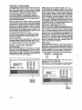
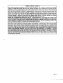
Three technologies to suit eve~ installation:
HARt)WIRE, SUPERVISED WIRELESS, 2.WIRE MULTIPLEX
VfSYA XMP COWROL
.
7
2.wlRE
MULTIPLEX
L~P
2.WE
mu
2wlRE
SM~E
DETECTOR
OW
:;,
8.%
EXPkNDER
~
,,RE#~
J
,UPT02
CANBEU5EDI
I
#
Ii>
t
o
42**
4275
Y
4192SD
4,92SDT
or4192CP
:~o~
41%
2W
TOADDITIONAL
2WIRE
lNTEL1!GENT
OEVICES
EXPANOER
-sFigure 1. 4t40XMP SYaTEM
Il. ZONE CONFIGURATIONS
.20NE TYPE
TheVISTA 4140XMP
DEFINITIONS
System allws up 10 S4 zones of hard-wire, pii~
.bp and/er wireless pm~ion.
Each zone must be
assigned m a zone type, which defines the way in which the system ,es~nds m fauns i“ that ZO”e. In add~b”, there are
three keypad adivated zones “(PANIC keys), a Wlfing Imp supwisbn
zone, and tw RF suWwiso~ zones, one far each
428o or 42W8 RF fl~tier
inswlled.
TYPE 1: ENTRY/EXIT
#1
TYPE 7: 24 HOUR AUDIBLE
Used for the prima~ enhylexit retie (ax front &or, main
This type also assigned to a zone mntaini”g a Panic button,
entrance).
but whkh will inhiate an audible alarm i“ addMon to an aIarm
re~ti to the ~ntral Station (RX bdside panti).
TYPE 2: ENTRY/EXIT
#2
Used for a semnda~
ent~/exit
route (ex: Garage door,
TYPE 8: 24 HOUR AUXILIARY
b%ing dodr dmr, bz~mem tir),
wbre more time mght b
This ty~ assigned ti a zone mntaining a button for “se in
needed to get to and tmm the mnsle.
personal eme~encies
or to a zone containing monitoring
deviws such as water sensors, temperature sensors, etc.
TYPE 3: PERIMETER
BURGLARY
Desgned to intirate an alarm repn to the Central Station ati
Used for etierior doors a“dlor windows which require an
on~ provides tinsole slam zounds and slam displays,
instant dam when vblatd.
WPE 9: SUPERVISED
FIRE
TYPE 4: INTERIoR
BURGLARY
(FOLLOWER)
Used for zones mntaining smoke deteztors, heat detetiors,
Used for areas where an ent~ delay k required only if an
pull stattins, etc. An own in this zone will initiate a trouble
entV/exit delay zone is tauK# timt.
signal. A shon in tMs zone will initiate a fire alarm (pulsed
etiernal sounder and rewti to central station).
TYPE 5: DAY/NIGHT
BURGLARY
Used for zones which mntain a toil~roteded door or window
TYPE 10: INTERIOR
BURGLARY
(DELAY)
(such as in a store), or to a zone revering a senstive area
~s type is simifzr to type 4, exmpt that entw delay hgins
such as a stock coom, drug supply rwm, etc., 01 othel
whenever sensors in this zone are vtilatad, regardless of
mntrolled access area where immediate notifi~tion
of an
whether or not 8n entV/exit delay zone w= faufted fimt.
ent~ k desired.
TYPE 6: 24 HOUR SILENT ALARM
This zone typ is genemlly assgned to a zone rnntaining a
Hold-up or Panic button that k designed to intiate an alarm
rewti to the &ntral
Statb”. bti which ptiu~s
no visuaf
dkplaW or alarm ~unds (ex: banks, jewel~ munterz).
BASI C 9 HARD-WIRED
ZONES
ZONE 1
TNS zone has a 350 milfise~nd
response and ca” be
assigned to any zone type and is set up for EOLR
su~wision on~. Ths zme k the Mly zone that =n supwfl
2-wire smoke detetiors.
See SMOKE DETECTORS sedion
for a Iia of mmpatible detmom.
@nnad all cbsedmircuit sen=rs in ~ries wkh one another
between
terminals
10 & 11 (see SUMMARY
OF
CONNECTIONS Diagram), The 2,000 ohm EOLR s~uld alm
be in series wkh the bop at the last devia.
1{the sensors used are open-circuit devbes, such as smoke
detetiors, each one must be in parallel to the next. The
EOLR must then be placed across the last wired detec!or,
M8simum zone resistan-,
excluding EOLR, k 1.00 Ohms,
UL NOE. The 4100 EOL resistor, rated 2.Ok ohms, must be
used on hardwire tire bow.
ZONE 9
This zone is unsupewised and an be assigned to my zone
type except fire. Only closed-circuit devbes can b used,
Conneti these devices in series with one another Wtween
lerminals 22 & 23 [sac sUMMARY OF CONNECTIONS
Oiagram). This zone can be programmed for either normal
resWnse (350mS, the defauft res~nse) or for fast res~nse
(lOmS), This zone is sutable for monitoring fat ading glass
break sensors or vibration sensors when programmed for
fast response. Avoid using mechanical magnetic or relay
tYPe contacts in this zone when programmed
for fast
rss~nss,
Note that the maximum resistance tor this zone is
300 ohms.
-6-
ZONES 2 THROUGH 8
These zones have a 350 millisernnd res~nse and can be
ass~ned to any zone typ. They ~n b EOLR supewised or
closed circuh unsu~ wised, as required (program field .41
determines whether or not these zones will use the 2,oOO
ohm EO~. Enter [1] in field .41 to d!sable the use of EOLRS
on zones 2 through 8). If programmed for use with EOLRS,
both closed-circuti and open-circuit devices can be used
with the 2,000 ohm EOLR resistor in series with tha loop at
the last devke. ft the use of EOLRS is disabled ~41 =1 ), only
Cbsd-irmit
devices an b used,
-
Zone 8 has the addd apati~fiy of sup~tiing 2 wire, latching
type glass break detedors.
See GLASS BREAK
OETECTORS se~ion for a fist of @mpatible detectors.
These detedors may be reset at the ansole in the same
manner as two wire smoke detetiors. (i.e. samnd entV or
.OFP sequence). fine 8 shouti & mnfigured as an EOLR
type zone when gla= break detetiors are used.
UL NOTE: The rnnnestion to glass break detetiors
apphcaMe for UL Listed applications.
is not
The maximum resistance per zone, excluding EOLR, is 300
ohms 101zones 2-7, ati 100 ohms for zone 8.
I
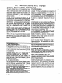
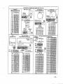
2-WIRE POLLING LOOP (Zones 10-64)
The4140XMP pmvkbs a buiti.in 2. wire ~lhng tip inteti~
IMPoRTANT:
Whti albws the n“m~r ~ ~o”es ~ h expanded f,Om th~.
basic 9 zones to up to 64 zones usiW varbus RPMs, ad the
4280 RF R=eiver.
See Mlow tar a tist of mmoatibla
sensors.
-.
The p)liing bop protides pcwer to sensors md sewes as a
mmmtJni~tbn
path hWeen the panel and sensom. Each
sensor mwt bc ~ignd
a unique address ID number (from
10+4) bfore being conneded to the plting Imp. Most
Senwrs have DIP switches for this pu~se.
See the DIP
SW~CH S~lNG
TABLE FOR POLLING LOOP DEVICES
for inf<>rmation on how to assign ID numbc~ using DIP
switches. Care must & tcken to cscign unique ID numbsrs
to a~!l senwr in order to allow the pcnel to supcwise and
pmvidll unique rnnsola status indications for individual
sensors.
@nne@ these sensors m Ieminab 24 & 25. Sensors ~n
bc rnnn~d
to a single run, or groups of sensors may bc
connect~
to sepaate wire rum wfiho~ aff~rng the pcne~s
abitity to suWwise individual senw~.
Follow the wiri~
inStrUtiOns provided with indtitiual senmrs (4190WH wiring
diagram is provided at the e“d of this manual). Be sura to
okewe ~mor ~ladty when wiring, The m~imum dbwcble
wire ru[l length bcwean the panel and the last sensor on a
gk9n wire run is as Ioibw:
Tha muimum mmbind
~ihng bop mn
i5 400@. h using shielded wire, the m~imum is 200W. If
Ionoer wire runs are neded. a4197 Lmp mender Mdule
mui be u4.
INTERCOM
INTERFERENCE
If an intermm system u bci”g used, the ~lti”g Imp wires
must bs as IW fmm the intemm wiring as ~ssible (minimum
~). If this spacing =nnot be achieved, shielded wire must
be usd. H this is not done, intetierence on the interrnm
system might -r.
Al= ntie that the m-imum total wire
length suppcfisd h ti in hati when shie~sd wire k usd.
ADVISORIES
The m~imum dbw~e
wrmnt draw on the ~lhng I@p is
84mA. Refer to the POLLING LOOP CURRENT DRAW
WORKSHEET (found in the POWERING THE SYSTEM
setion) for current draws of various Plhng Imp devices. If
more than 64mA is being drawn, use of the 4197 provides
anaher @ wdh UmA avtilatie.
Make ~tiain to include the total current drawn on the @lling
m in !he AUXILfARY CURRENT DRAW WORKSHEET (SW
POWERING THE SYSTEM se~ion) when tiguting the total
auxila~ I@ on the pme~s pwer supp~.
m“’’”
POLLING
.-.
LOOP
OEVICES
see
l~ERIPHERAL
DEVICES
compatible
polllng
loop
smoke
passive
infrared
motion
detectors.
section
deta~tor~
for
gnd
4208 Eight Zone Polfing Loop Expsnsion
Module
. Used to supemise up to 8 hcd.wired devkes via the Plfiw
hop. KIOTE: Does not suppn 2-tire smoke detmom.
. Set DIP switches to identify 8 zones.
.
. The first two zones can
= -a
~=be etiher normal or fast
response (DIP switch
m,==
selectabla),
.=..—
. All zones are EOLR
supervised
(first
six
zones S. 4,7k ohms, laa
two zorles = 30k ohms),
provided with the 4206.
B
,.<-
4190WH Two Zone Remote Point Module
. Used to supewi~ 2 hard-wired devims via the Wlfing tip
. DIP switch programmable.
. The left zone can be
EOLR supervised,
if
necessary,
and can
accept either open or
closed circuit sensors.
e
The
right
zone
is
unsupewised
and can
accept closed circuit
sensors only. Refer to
H
4190WH
the
OPERATION setiion at
the end of this manual
for more informatbn.
4f 94 Surface
Mounted
. Wide gap sudace
mounted reed rnntact
with built-in
RPM,
which is DIP swkch
~rammable.
Reed
Contact
(Wide
Gap)
w
4197 Polllng
Loop Extender
Module
Can be used if the 2-wire ~llng Iwp mud be greater than
the remmmanded length (4000- max). By insalting a 4t 97
at the end of the first loop, the polling loop can be
rnntinued. Mmore than 64mA needs toba drawn from the
Wlting loop to Wwer RPMs, use of the 4t 97 provides
aother loop wfih 64mA available.
tinnects to the p)fing
loop and is powered
from auxiha~ ~wer or
q
by a separate
729
m—
power
supply
with
bafte~ batiup.
—-—
- —~~:~c==a
-.—-.--~=.~~--* =---..—-,
n
figure 2. Polling Loop Davi=es
-7-
WIRELESS EXPANSION {Zones
..–
.-—--- 1-63) ,
4280/4280.8
RF RECEIVER
31 It, wkhin a pr~rammed inlawal of time, the 4280 dms not
The VISTA XMP system suppotis
up to 63 wireless
hear from my of tis transmhtars, an ALARM or TROUBLE
Iransmhtws (5700 series), DIUSa 5727 wireless kevoad. To
will h displayed de~nd!ng on the res~nse programmed
expand lhe “system using’ wirelass, ona or two 4280 RF
for zones 88& 90 (fieMs 1.08 & 1.09).
Receivem (or 4280-8 ti only 8 wireless zones are used) musi
ba rnnneded to the polfing loop. Tha 4280 ra=ives status
HOUSE
IDENTIFICATION
and alarm signals from wireless transmitters (@345 MHz
The 428o reswnds on~ to transmhters with the same house
USA 315MHz Canada) within a nominal range of 200 feet,
ID (DIP switch pr~rammable
from 01-31). Ttis prevents
system inletierence
from transmitters
in other neatiy
and relays this hformation to the =ntml via the ~lfing Imp.
Two 4280s can be used to provide either a greater area of
syctems. To make sure wu do not chmse a House 10 that is
mverage, or provide redundant prmedbn.
in use neatiy, pm the system in the SnMar Male, which is
describsd Iaterinthbsedbn.
IMPORTANT:
Note that if using tw RF R~eivers, one of
them must be powered from auxifia~ power. For mora
information regarding the 4280 installation, refar to the
installation instrutiions provided with the 428o.
NOTE Unless stated othewise,
references to Ihe 4280
Receiver represent the 4280 andbr 4280-8 Recebem.
..-—
-,-....
‘“--
II
11
~
RgUW 3. 4280t4SS0.8 RF RECEWR
PROGRAMMING
NOTES FOR WIRELESS
DEVICES
All RF zonss mud ba designated as such in their raspatifie
program fields (t.1 S-1 .25). Any zone from 1-83 ca bs
des@nated as an RF zone. To enable a zone as wireless,
simply enter a “1. in the lo~tion for that zone. B* careful
when designating
RF zones. if you want a zone 10 ba
either hard-wired or on tha ~lling
Imp, but ~identally
en~le k as RF, the system will ignore that zone. RF enable
overrides hard-wire! h using a 4280.8, a“ly “p to 8 ZOMS mn
be enabled as RF zones. lf more than 8 zones are enabled,
the massage “SET-UP ERROR. (51 37) or .E8. (41 37/4127)
will be displayed.
SUPERVISION
Each transmitter (except 570! and 5727) is su~wisad
by a
check-in signal that is sent to the receiver at 70-90 mintie
intewals. If at least one Cheti-in
is not ramivsd from a
transmitter within a programmed intewal (field 1.31), the
con=le will display the transmitter numbsr and ‘CHECW will
be displayed,
Each transmitter
fincluding
5701 and 5727) is also
supewised for low batte~ mnddions, and will transmit a low
battery
signal to the 4280 when the batte~
has
approximately 30 days of lie remaining.
NOTE: After replacing a low or dead batte~, activate the
transmfiter and enter the security ade + OFF to clear its
memo~ of the .bw Batte~. signal.
The 428o itself is also supewised three ways
1. If the cover of tha 4280 is removed, an ALARM or
TROUBLE will be displayed depending upon the reswnse
programmed for zones 89& 91 (field t .09).
2. If the connection is broken between the 428o and the
control panel, or the 428VS rover is removsd, an ALARM
or TROUBLE will be displayed depending on the response
programmed ior zones 89 & 91 (field 1“09), This response
is usually that of a DAY?NIGHT or 24 hour type.
-a-
~
-
TRANSMITTER
IDENTIFICATION
E=hlransmftter
has fis own unique ~num@r(~ne
#),
wtichis DIPswitch programmable in each unit. Whenevara
transmi=ion takes plaa, either for an alarm, fauft, check-in
‘or low batfe~, thk ID numbr is sent along wth the mess~e
to the 42a0 which, in turn, relays this information to the
mntroi panel, which disdaysthemndtion
and zone number
on the console. See the OIP SWITCH TASLES FOR
WIRELESS DEVICES af the eti ~ this mmwl, for itii~ual
transmhter settings.
SNIFFER MODE TO OETERMINE
HOUSE ID
(Code+
[#] + 2)
To ch~
Ior house IDs baing used in neatiy systems, set
the DIP swtches in the 4280 fora House lDof .O~ (all
switches up), thenenter your.lnataller tide. +[#]+[2].
The
4280 will now .sn~ OM any House IOS m the area ad
display them. Keeping the 42a0 in this mode for *M
2
houm will ghe a gd
ind-n
of the hauw 10s Wmg usad.
To exit the SnMer Mode, simply key your installer mde +
OFF, then set your house 10 to one not ds~ayad in lhe
.Sniffer We..
sNIFFER MODE TO CHECK TRANSMITTERS
(Coda + [#] + 3)
To check that all transmhtem have baen aet for the pmpr
house 10, set the 4280 to the pmxr houso ID and entsr the
ln~aller de
+ [#] + [3]. All trmsmitfer ID numtirs thct have
the house ID set for the 4280 will ba dnphyed wtin each
transmitter number che~
in (up to 2 hours). A f~er way 10
do this is to fault each transmitter,
which causes a
transmission to ba sent to the 4280. Chink that tha ID
numtir is displaysd when the transmftfer k f auft~.
GO/NO GO TEST MODE (Patented)
Ttis mode helps determine the best Iocatio” for each
transmitter and is adivated by p~ing the rnntrol pael in
the TEST mode and removing the 4280’s cover. The
receiver’s senstiivity is reduced by half. Once transmitters
ara placed in their desired Io=tions and the approximate
length of wire to be run 10 sensors is mnneded
to the
:ransmhter’s wrew terminals, own circuit each transmitter,
& not mnduti this test wdh your hmd wrappsd around the
transmitter.
If a single 42sO is used, the mnsola will baep three times to
indicate signal reception. H tw 4280s are used, the mnsole
will beep ome i tha first 4280 recetied the signal, mke t the
second 4280 received the signal and three times ti both
re-ivers
heard the signal (which is desirable for redundant
configurations).
ff the consoie does not beep, reorient or move the
transmtiter to another location.
To exit this mode, replace the 428VS aver, then enter the
installer code and press OFF. Note that the Receiver’s
sensitivity is fully re$tord when the cover is replaced.
\
IMPORTANT
BA~ERY
NOTICE
The VISTA wireless transmhters am desgned to pmv’de bng
batioty Itie under normal ~pe,ating renditions. Longevity Of
balloties may ba as much as 4-7 yaars depanding on fha
environment, usaga, and tha Spacifc wireless device being
used.
Eflernal faders such as humidity, high or low
tem~wtaturas, as well as Iafge swings in temperature may all
reduce the aaual batte~ life in a given installation.
The
VISTA wimlesa system can identify a true low batta~
stuatian, thus alfowing the dealer or user of the system time
to arrange a change of bafte~ and maintain pmtastion for
that given pint wkhin the system.
-..,
WIRELESS
ZONE TYPES
Each RF zone m h programmed to ras~nd ~ any zone
tYP@such as ENTRYEXIT, lNTERfOR, PERIMETER, @tc.
(see the section under ZONE TYPES for a mmplete
explanation of each zone typa). Desired alarm ras~nses
=n ts broken down az folbws:
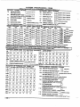
ZONE TVPE
Entw/Exil Burg
Perimeteraug
lntatir Wq
Fim
24 W, P&
Jsifant or atiible)
Day/Night Ourg~
24 HourAuxiliaV
TRANSMITTER ID #
1@m”qh 47.
1 timugh 47.
1 fiwgh 47.
32 thw h 47. (5775)
4Stiwgh 63.
46 timugh 55.. (57N)
46 thwgh 67
62 WW-. (57O1)
1 tim”gh 67.
1 hmugh 47.
O. Using W Rarnivers does not increase the numbar of
transmitters the system san suppofl (63 transmitted,
plus a wireless keypad).
6. Refer ~ the mcsimum polling hp wira runs de=ribad in
the POLLING LOOP sa3fion whan rnnneding 4280s to
the polliW hop.
lMPORTA~
The muimum mmbined polling kmp run
is ~.
K using shbM6d tire, tha mzsimum k 200V.
NoES:
-LESS
OEVICES
See
the
PERIPHERAL
compatible
wireless
paasille
Infrared
motion
OEVICES
section
smoke
detectors
detectors.
57o1 Panic Transmitter
. Pmgrmmable for either silent or audibb
24 kur _
(DIP switi prwrmmd
br
Zme$ S2 w 63).
5711 Sllmllne
Ooor/Window
Transmitter
. Can k used with any closed circuit
mnsor. NOTE: Can b usw Q“ ay z1.63 but, it Pqmmmed for zones 3247,
them will k a 3 minute fock-out bameen
Uansfnissions.
5711 WM Ooor/Window
Transmlfter
w/Reed
Switch
. Sfimtire dmrmindw aansmi”w with built.
in rrnd Srnmh (magne ncludad). Cm &
used with any closed circuit sensor.
NOTE: Can be usad on my zone 143 bm,
if pmg~med for zones 32-47, tiem wiM
be a 3 minute lock-out beween
uansntissions.
.-
5716 ~oor/Window
Transmitter
. Cm be usad witi my opsn or dosd cirmit
sensox (DIP switch selectable), and
features a built4n reed switti. NOTE: Can
be used 0. any Zcne 1-63 but, if
pmramtiti
for zoms 3247, tiere will k ~
3 minuie Iokaut Mwen transmissions.
ADVISORIES
1. Do not Dla@ transm~em on or near matal obiads. This
will dec;aa6a range and/or blti
lransmissbns;
area for Wst
2. Place the 42a0 in a high, mntrally l-ad
r~ptbn.
M not placa r6miver on or near metal o~aas.
3. The 4280 receiver must M at least 10 feet from the
Controf panel or any ramote consoles to avoid
intedarenm from their micmprocessor.
4. When connetiing
a door~indow
contact to a 57t i,
5711 WM, or 5715 tmnsmhmr, avoti a wire fangth of 20.24
inches. Thk paflicular length decreaws range. A shmter
or bnger Ia@h haz no effacf.
For UL Household 9urglaV Installations, wimtf loops
mnnaed
to these devicas =nnot axcaad 3 fact.
5. If dual 4280s or 4280-8s are u=d:
A. Both must ba al Ia=t 10 f6at from e=h other, as well
as fmm the @mml panel and remme mnabs.
B. One of the 4280s or 4280-8s must ba Wwered from
Aux. power so u nd b ax-ad Sd mA Plfiw IMP current
rating.
C. The kusa IDs must ba the same.
for
and
o
B
9
571 5WH
Universal
Transmitter
. DIP switch sebctabk for fast response,
-n
as dosad dwit sensor usage, md
has a hmwr profected cover, use in
aPPficatiOns where open circuit heat
detectors are needed or where fast
msmse deri-s am naa~.
NOTE!Can b usti w my ZOM l= hi,
Hpmgmmmad for zonac 32d7, hem will
be a 3 minute lock-out beween
~nsmissions,
5727 Wlrelees
Keypad
. WImless keypti that =n h US4 to Wm
the burglaw protection on and off, and
faawms the same built<n pank tinctions
as wirad consoles for either silent w
audble 24 Mur dam. & LEO indiation
hghtseach time a kw is Pres- to verify
transmission (LED Iocatad in the ~]
READYkey).
. W keypd is idntifids
Z.W.~
wh
it Imnsmits low httew messages. The
kYPad Panicsam identified as .W for ~)
+ [s], WF for [#l+ [3], md %~ for ~] + [1]
if ~mmm~.
B
u
H
.L,
.,,
,.,
. .
.
.
-9-
Ill. PERIPHERAL
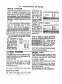
REMOTE
CONSOLES
The 4140XMP suppies up 10750 mA 01 auxilia~ pwer for
remote consoles, polling bop devices andlor other auxiha~
devices such as motion detectors
or 4-wire smoke
deteaors.. The 4140XMP suppotis, independent of auxilia~
power rnnsiderations, up to six 4127, 4137 or 5137 remote
mnsoles. All mnsolas may ba pwerad from the auxiiia~
~er
outpul prov~ad that the total current drawn fmm this
otipti doss not excaed 75o mA. You must keap this in mind
when adding remola anwles
so you don? overdraw mrrent
from the panel. This WOUMresuh in a batta~ which does not
charge proparly or possibly a trippd
auxiiia~ solid state
circuit breakar,
ff the auxila~ load is dalarminad to M greater than 750 mA,
than addtional mnsoles (total of 6) can ba powered from a
suppiementa~ ragulated t 2vDC power supply (e.g. 487-12
suppiias 12V, 250mA; 486.12 supp~es t 2V, 500mA).
Connect the consoie,s
rad and black Iaads to the
suppbmenta~
supply-s positive (+) and nagative (-)
terminals, Also mako a co””etiion
between this suppiyIs
nagativa (-) larminal and tha 4140xMPs Auxihay power (-)
terminal 7 so that kth hava a common ground referame.
NOT : Co”sobs mnneati m s“pflewn~
power supplies wh~h
do not have a ba~up batie~ will no! o~raw w~n AC PWM is
lost. [n tirs w% make sure m Wwer a! least one mnsde IWM tk
paners auxilia~ power output. The pa”ers ba~up bane~ will
~
. 4-wire smoka dataaors
3ppflcati0ns.
4127 FIXED-WORD
LCD
Compact dssig”, ~ip~
wilh a fiquid c~swl display
(LCD} us!ng 2digi~ n“metis
~~~:=~~::f::~~~:
language prompts, such as
‘-OY,
‘NoT READY, ~.
for sysmm $titus. A built-i”
alarm sounder
is also
indudd, winch elimim~s tk
n-d {or a separate intior
swtiw. ~mA cumenttiaw.
=TtRNAL
cannot
be used in UL Listad
CONSOLE
‘——–——
4137 DELUXE FIXED-WORD
EquipMd witi a liquid c~sml
display (LCD) using 2.digit
numerics
for
zone
ide”tificatio”, and a set of
pre:desig”ated
English
la”g”age prmpt%, such a%
.READV, .NOT READY, em.
for system smtus. Keys m
backlit. A built-in alarm t
sounder is also iwlu~,
whi& elimi”a~s the n-d for
a separate i“&or sounder,
6W amnt *w.
5137 ALPHA CUSTOM LCD
Equipped
with
programmable 2-Dne, 32?
*aracler (16chamaem ~r
tine), ALPHA-NUMERIC LcO
for
ccmplete
zone
idemificalion
in Englisti
language fif descriptors am
programmed). Keys are also
backlit, An alarm sounder is
built in, eliminating the n-d
for a separate in&Or soun*r.
90mA wnent drew.
w
CONSOLE
CONSOLE
h!
WIRING
Consoles
consoles
maimum
homerun
-I
_
LcD
1
may ba wiradto a single wire run or individual
may be sonnetied to seDarale wira runs. The
wire run length from the p’nel to a sonsola whiti is
bask to the panel must not exceed:
–—=..
-.mmm
. . ..
FJmm
-,.“. .gmm
mmm
‘-
E
SOUNDERS
RELAY OUTPUT
The 4140XMP providas a wet bell ralay output which is used
to ~wer external alarm soundem. Conna&ions ara mada to
terminals 4 (positive output) and 5 (negative return). See
SUMMARY OF CONNECTDNS Diagrm.
UL INSTALLATIONS
For UL installations, the total current drawn from this output
and the auxiliary Wwer output, combinad, cannot axceed
750 mA, In addition, the sounting device must be a UL Listed
audible signal Wpliance ratad to operata in a 10.2-13,8 VDC
voltage range, and must be mounted indoors. Example:
Whaalock Signals Inc. siran model24T-12 (provides 85dB[A]
for NFPA 74 a Standard 965).
IMPORTANT: Going beyond these bmits will overload the
power supply or may possibly trip the bell output thermal
circuit breaker.
NON-UL
INSTALLATIONS
The total current drawn from this output cannot exceed 2.6
amps. A batiery must be installed since this current is suppliad
by the batlery. Up to two 702 sirens can be used, wirad ill
series. Up to two 719 sirans can be used, wired in parallel.
-1o-
DEVICES
=::::
250 feet m=
runs
combined
must
not
62s feat ma
900 ,eet ~=
unsh)eldad
quad cOnductOr
cable is used (45o fact if
If more than one rnnsole is wired to a run, than the above
m~imum lengths must be dwided by the number of mn301es
on the run (i.e. the maximum length would b 125 feet i WO
--. –.,..
..
---mnwles are wlrea on a *U gauge run)
Compatible
SOUNDERS
702 Outdoor Siren
. %Il+ontilned siren (&iWr built-in) and Weathrpmof br outioor
“se. Ca” k wirti for eitier a stea~ or yelp sound and is ,ated a!
120 dB @ 10 feel. This siren =n also be mmwr promcwd, or ~“
be mounted in a metal cabinet (?16), which can be mmpe,
prmected.
719 Outdoor Siren (Compact)
. Compaa, SIlantiwd
siren (tilver built-in), and weatie~mf
for
outioor “se. Can b wired tor a Slea@ or yelp souti, md ramd at
90 d6 @ 10 feet, A ~wr
vomcld 7088E &Wt
is avaikbk.
740 tigh Inlensity Sound-r
. Compact high intensity soutier ramd at 123 dB @ 10 fwt, This
so.”der emtls an ear pie%ing-, tigh kequency sound, and ~“ be
mounted i“dw~ (bracket in.l”&d) or O“ttiors (in 703BE ~bi”et),
AES1031 Motor Eel{ & Sox
. AMSECOmotor &ll & bx, rated at 81 dB @ 10 I*I.
PA400S (beige) lPA400R (red) Indoor Piezo Sounder
. BRK indwr piezo sounder(rti or hige), ra=d at W dB @ 10 Iwt.
“
SMOKE
20NE3
DETECTORS
When progmmmed = an EOLR sumwised FIRE mne (tym
09 in program field .02), up 10 sixteen 2-wire smoke
dtietiors
can be used. When programmed for fire, the
smd
~DE + OFF sequenm momemwi~ intemupts power
to reset the smoke dmetiors.
~MATfU
~KE
DETECTORS
DETECTOR TVPE
BRK MODEL
Photoeletirk, dired wire
BRK24D0
Photoeledric wheat sensor, direti wire
8RK2400TH
Photoeletiric wA401 B base
BRK2451
Photoeledfic wlheat sensor and B401 B base BRW451 TH
Ionization, direti wire
BRK1400
Ionization w/B401 B base
BRK1451
Photoeletitic duti detaaar wmH2851Dc bsm BRK2651 DH
Ionization duti detnaor wfOHl 851 DC ~se
BRK1651DH
ADVISORIES
It the EOLR is not at tha end of the Iwp, the zone is not ful~
supewised. The system will not respond to an open cimuh
within the zone. The alarm cument provided by this zone k
su~lcient to suppofl operation of on~ one detador in the
alarmed state. Refer to the maimum pclhng Imp wire runs
hsted in the POLLING LOOP setibn when using ~lKng bcp
‘“*’
‘ete”ors’
q,,
.,
.
@
@@ ~
4192sD
~lR
MOTION
Amid beating the unfl !n dtrea sunllght or d!,eti~
above
. Amid beating the unt on unst~le sutiaces.
F. Avoid running alarm witing close b hea~ dufy elmri~l
POLLING
LOOP PIR (4275)
Tho 4275 is a dual element
p=sbe infralti
delemor, wth
a built-in
RPM,
that
is
connected
directly
to the
2-wire Wlliw bcp.
,.---
I
be used i“ UL ~~t~d
f~-1
~!
H
~
ZOne 6 -n
suppofl 2-wire, latching type glass break
detectors when configured as an EOLR supewised zone.
The sarnnd COOE + OFF sequence momentarily interwpts
rower to this zone IO reset devbes wired 10 i. Use datedom
whkh are rnmpatible with the ratings bebw
Standby Voftage:
5VDC - 13.6WC
Standby Resistance: Greater than 20k ohms (equivalent
resistance of all deteaors in paralial)
Alarm Resistance: Less than 1.Ik ohms (see nma klow)
Alam Cuwant
2 mA -10 h
Reset Tree:
Less than 6 sands
UL NO=: tinnedion
of glass break detedors to zone a is
not ~rmittti
for UL Listed a~lications,
POLLING
LOOP PIR (4196/42T8)
The 41 96/4278
are quad
element
passive
infrared
deta~om with a buiH-in RPM
that is mnnected dire~ly to
the Z-wire polhng loop. The
~.’
detatiors feature an auxitia~
sensor
loop that permits
m
Wnnetiion of another neaby
Q
alarm sensor (reed contaa,
etc.).
WIRELESS
PIR (5775)
The 5775 is a batte~ opratd,
wireless, dual element p=stie
infrared motion dete~or that
can & monitorti
by a 426o
(4280-6) wireless
receiver.
The 4260 is wnnectd
to the
2-wire pclti~ hop.
I
I
POLLING
LOOP SMOKE OETECTORS
(4192SD,
4192SDT,
4192CP)
Can be addd to the 2-wire PolliW Lmp o“ ZO”eS 10 thm~h
64 (as programmed in fields .03, .04, “05, 1.01, 1.02, 1.03,
1“04 and 1.05). These detwom have a built.in RPM whch
is DIP swtch p~rammable.
They are wird in parallel to the
plting loop, and do not need auxiha~ power or a separate
reset switch. The ~lting loop provides power and reset
signals to the detemors, as well as alarm and trouble sgnals
fmm the detetiors.
Dt i kCTOHS
NOTES ON P(R MOUNTING LOCATIONS
. AvOid locating the unti whe,e cem,al heating ,adiatOrs,
flames or heating outlet duas are wittin the prmetitie
GLASS BRtAK
U“not
5T0a
Selwt a mountino ske wkh the followina notes in mid. Sea
wverage will b-obtained
if the mou~ting site is seled~
such that the tikely diretion of intruder motktn u across the
patfam of pmtedion.
,-.
. 4-wire smoke detedors
appli=tions.
WIRELESS
SMOKE DETECTOR
(5706)
One piece photoeledtic
smoke dete~or
with built-in
transmitter (DIP switch pmgrammabb
for zones 48-55),
Built-in 85 dB piezoebmrb alarm sounder and autible bw
ktte~ warning,
-a
‘J
20NES 2 THROUGH 8
These zones can sup~ti as many 4.wire smoke detedom”
as -n be pcwered, wha” p~ramed
~ a FIRE zone, t~
09, in program fieti .02. There are on~ two requirements:(1)
The zones must be mnfgur~
for EOLR su~wisbn,
ati (2)
a normailyalosed,
momenta~ swhch must M instdld
in
seties wth the power to the det-om
in o~er to allow reset
of-the smoke deteaors after an alarm. The detmors must
b wired in parallel, with the EOLR at the last detmor for full
su~wtion.
To su~wiw
power, a BRK No. A7771 601 EOL
Relay Mule
k rammended.
i! / ‘+
~~;
1
u
Tha IEI 735L saries detaaors have been tested ati tound to
be compatible with thesa ratings.
Up to 50 IEI 735L
detetiors, connatied in parallel, may be used (the alarm
currant provided by this zone is sufficient to suppofi
Omratbn of onb one datetior in alarmed state), Follow the
manufamurer,s’
recommendations
on proper detactor
installatbn.
NOTES: Detetiors which exceed 1.1 k ohms in alarm, but
maintain a vokage drop in alarm of less than 3.6 volts ~n
ako & usti.
Use of NO. or N.C. mntatis on the same zona may pravant
proper glass break detaaor opration.
-11-
PHONE
LINE CONNECTIONS
Inrnming phone tine and handsel wiring is wnntied
to the
main terminal bloti = follows (reier 10 SUMMARY OF
~NNEC~S
Di~rm):
TB1-26:
-1
Hand%t UIP)
TB1-27
L-1 Hand=l (RING)
Inmming Phni U* ‘~)
tii-26:
Inwmiw Phone Line (RING)
TB1-29:
Hit k desird m mnnthe Wnel m phow In= Iha rwfuire
ground stati =pebili,
then a 675 Ground Stan Mtiule.
mu6t k u*.
This mdub is triggerad by one of the mdpfi
on the mnnmr
l~ld
J7 (s8 ~NNECTOR
J7 TRfGGER
OUTPUTS).
“The 675 Ground Sta
CONNtCTOR
IMPORTANT
Hthe aommuntior
k rnnnetid
to a tebphone hne insMe a
PABX, k sure Ihe PABX has a bati.up pwer supply that
=n su~ti
the PABXior24
houm. Many PABXs are not
power ba~~
up and rnnnedbn to such a PABX will resuh
in a mmmuni=tion
failure
t war
k Ioet.
Module k mt UL LMad.
J7 TRIGGtR
OU~UTS
GENERAL
INFORMATION
hnne~or J7, Imtad on the @h! hand stie of the man PCB
pwides 4 tr@ger oows
for owratiw
the 675 Ground San
Module! the 4146 Keyswficti,
and for !riggeting auxitia~
am
sgnalting ~uipment (LORMS, SWS, em.)
The pin a~~nments of thk rnnn~or
are shown balow. Use
only the 4142TR 9-wire c~le (available = a option) for
mting mnnatiions to this mnnetior.
Each o~ti
b ratd m follow:
When Adtited
10. 13.6 VDC through SK Ohms
Whan DM~watad:
1K Ohms to Ground
OWW 1 o~rates, ~ defauh, as a trqgerfor the 675 gmu@
stafl mtiule,
~~ ompw may optionally * p~rammd
to
oWrata m an o~nlclose
trigger. Onfy one of thesa options
mW k ~ed at any time.
Outputs 2 & 4 oparate, by defautt, m Fire and Silent
Panic/Oumss triggem raspetilvely.
These ttiggam may
optionally h programmed to ad as Arm and Ready status
indi=tors when it k desirad to usa tha 4146 keywkch
. The Mtial
WARNING:
To prevent the risk of shock, disconneti
ptine hn~ at Ie& ja~ @tore seticing the ~nel.
4146 Kayswtich S nm UL used.
(Ground
Stan
GROUND START
Not Intandad
for
Module,
KeySwltCh,
MODULE
u8a In UL Llated
etc.)
appllaatlona.
An optional 675 Ground Stati module can be used for
installti(om
haviW tekphona lines which require ground
stafl imtead of tip Safi opeti!on to obtain dial tone from
the talrn cemml offi~.
ff usad, p~mm
fiald 1.46 mus &
set to “0- (iadoW dtiautt) and the 675 Ground Stan Modub
must k oonntid
to the ~ne~s J7 mnn~r
trigger ompti
1, to uxiibw
Pwar, and to tha %ING. skfe of the telaptine
~nes sbm
in tha diagmm k~.
Use the folbing
p~dure
Iakphme hm is the .RING
ti determina whch side & tha
stiw
a. ~nnti
tha “+. lead of a OC vokmatar w ~tih
and tb “-. bti m om stie of tha teb~na
fine.
b. The tira wheh reads +WVDC k tk
ground,
%ING. stie.
When Ik panel h= a m~~ge
to tfansmti to the mntral
station, it will seke the tine, go off hmk, and then tr~ger the
675 mtiule to wnnaa tha .RINW side of tha telephone tine
to eaflh omund. W oanal will ~usa the mdule to bm~ the
Mnnatiin
kmaen
‘.RING” and eamh ground when a dbl
tone is obtaind.
.,@xM,
,7 C“NNCCTOU
CABLE
OUT,: GRO”NOS,-1 OROPE.,CLOSC
0“, 2 ,,RE m KE”S*!,CH ARMEDLE.
0“1 3. BURGUR”,A”D,BLEWN(C,.”XIL ,6,”
OUT4: S,tiN1 PANICm”RESSOR tiE”SW8TC”~E&D” LE.
Figun
-12-
4. CONNE=OR
J7
ngum
5. GROUND
START
MODUU
w
REMOTE
KEYSWITCH
NOTE:
4146 Keyswltch
18 not
If the keyswitch option is seieaed
trigger oufpti
are disabled.
-.
UL aDDrOVSd.
(fiald “15), the alarm
An optional Remote Keyswitch an be used for remote
arming and disaning
of the system. If used, program iield
.15 must h set to “1. to enable the keyswitch option, and
the 4146 keyswtc~s normalfy open momentay switch and
EDs must & wnnetied
b tine 7 and to the J7 wnnemr
ttigger omputs respetiiveiy.
A 2k EOL resistor must b
wnneaed
across the sivkch r~ardless d whether or not
zones 2-8 are seleaed to use EOL resktors. See diagram
bbw.
An optional cbsed~ircuk tam~r switch (model 112) an b
wired in series wtih zone 7, w that, if the swi!chpla!e is
removed from the wall, the tamper will open, disabting
keyswkch o~ration
unttl the syqem is nefl tisarmed from
the rnnsole.
NO=
Onfy one kayswtch wfih LEDs -n
the syslem’s power suDP&.
I
be suppned
by
follows:
f
,,,
A momenta~ shon across lhm zone will arm the system in
the .AWAV mode. If the shOfl is heid for ~are than 3
seconds, the system will arm in the .STAW mode, ~.e. all
zones designated as zone tyWs 4 or 10 will be a~omatiml~
bypassed). After the system has bean armed, the ne~ lime
zone 7 is shon~, the system will tiswm.
-”,
I
.,
BROKENUNES REPRESE~
INSTWMR WIRINGCONNECTIONS
\&KMED)
,-----------
,Rmv,
----
.-.
---
I
It
----
I
----
---------
—--__-,
------e,--ThMwn
WITCH (N.C.,
,, KEYsWITCMIS uSED,
,, OUT, Cm S,,U BE“SEOTO P.W,DE
GROUNDWM. OPEWCLOSE,s~ F,U
2) ~
2,3,4 NOLOWER PNOWDE-M
ST-US lNDlul,ONs. Om 2 &, WWE
REYSWITCHEm. Om 3 IS NOTUS~,
~LV %XEY~CH
cm BE“SEO.
31Z~E 7 IS NO LNOER UW= @ A
PmTEcT,w ZONE.
10 ERM.
20
, . al.
Lx.
SWITCH(N.O.,
TOZWE 7
10 XRM. ,,
—
----------?
p’
L---
1
:“y~
/
$
Eow
4,.. KEVSWIW
[.01 UL LET=>
figure
6. REMOTE
KEYSWITCH
WIRING
-13-
.—
IV.
MOUNTING
AND POWERING
THE SYSTEM
MOUNTING
MoUNTING
THE 4140XM? ‘PC BOAUO
Before mounting the circuit bead ‘be cenain that the
~mpriate
me~l kntiuw
have been removed. DO NOT
A=MPT
TO REMOVE THE KNOCKOUTS A~R
~E
CIRCU~ SOARO HAs BEEN tNST~.
1. Hang the three mounting d~ on tkc miscd ~net
tcbc.
Obcewe pm-r
ctip orient~hn
10 avoid damage b the
chp when mouming ccrews are tghtencd and 10 avoid
pmbbms tih imetibn ad rmvd
d the PC Wti.
2. Insen the top of the circuk bard into the sbts al the top
Of the ~inet.
M*
cenain that the ~ati
rastc in the
sbts ind~td
in ccep 2 de~il.
3. Swing the b~e of the bard itio the mounting c~is and
secure the bard to the cdinet whh the a~mpanying
ecmwc (as illutmtd
in step 3 detail).
ADVISORY
Make -tiain
that the mounting ~rew
are reason~ly tght
~ insure that there is a gd
ground rnnne~ion tieen
the
PC bwd md the mnet.
Ah, dress fmti wiring awW fmm
the micropmesso,
(tinter) section of the PC tiad.
The
=binet provides 2 Imps on its hft and right sidewalls for
anchoting field wiring using tie wrapt.
These stew are
imptiam to minimtilng the rik d pnel RF intetierem
with
televisbn rmption.
MOUNTING
THE 4140XMP
LOCK
1. Remove the Iti
kno~om on the mntml tiinet
rover.
Inseti the kcy imo the Iti.
Postion the I*
in the hole
recking Mnain that the latch till m~e mmaa wtih the
Ietch bm~et when the dwr is doccd.
.T-
2. While holding the 1A cteady, insen the retainer ctip into
the retainer slots. Position dip as illustrated in the
diagram m the nefi page to f~ltate
e~
remwal.
-
MOUNTING
THE 4127 CONSOLE
1. Sepamte the rnnsoie from hs ba~plate by removing the
two swew fmm the mp and bttom edges.
2. Usa the ba~piate to mark the ~shiins
on tk wall @r the
screw mounting holes and the cti~ut
for the intetiam
wiring. Use wall ancbm for the screwc md m~e the Mout in the wall no larger than indimted on the template.
me backplate k designed to be direaiy moumed to ether
a single or double gang eldfical
bx.
3. Pull the intetiace wiring in the wall through the c~-ut.
-14-
4. Pass the intedawiring through the opening in the
b~late,
then mount the ba~plate to the wall sutiace
wtih screws.
5. Splice the intetiace wiring to the wnsole wires. Insulated
solderle= w;re splims (eg, Ademm311 ) may be used for
splicing.
6. Attach the main kdy of the mnsole to the wall-mounted
ba~plate. The rnnsole is properly attached when it is
screwed to the ba~plate by the top and bottom screws
previously removed.
.--.,
SURFACE
MoUNTING
THE 4137/5137
CONSOLES
1. Use the template provided (On a separate sheet) to mak
the ~sfibns on the wall for the screw mounting hola$ and
the ti~ut
for the witing.
\
2, Pull the intetiam witing in the wall through the ~~ut.
3, Remove the mn~le,s back rover. me securing screw at
the front of the wnsole must be removti to release the
bab rnver
4. Pass the intetiace wiring throWh the opening in the ba~
rover, then mount the b~
wver to the wall suda~ with
screws.
~i,eS (or to the
5. Spfi~ the inteda~ wiring to the ~“SOIe
wires on the intati~
mnne~or
supplid with 4137s),
Insulated solderless wire spfims (eg. 311) maybe USW
for spticing.
4-
6. Mm
the main my of the wn~le to the wall-mountad
back ~ver. The m“sole
is properly attachad when i
snaps into place. Use the sacuring screw (previously
ramoved) to %cura the ~nsola to the ba~ rover
-0.
WHFACEMOUmNOCO—
—
FLUSH MOUNTING WITH TRIM RING KIT {5137TRK)
1. Cut oti a 4sf4. Mgh by 8- wide opening in’ the wall ‘ 3. Install the ttim ring into the opening in the wall with the
hinge clasps to the right. MWing sure the tdm ring is
bmween studs, no le~ than 1-1~- fmm eithar stud. Use
straight, tighten each clip screw, making sure that the
the templae provided to mark the ctiati,
attached cli s(ties down inb its guide trati,
2. Ir\sefl the four 1-1/2. long #6 screws through the
4. Install the Gnsole * follows: Engage the hinge clasps
mounting holes in the Trim Rng and than attach tha four
on the ttim ring with the notties Imated in the b~ (rightmetal securing clips, as shown in tho diagram. Use on~
hand side) of the Gnsola’s front panel. Swing the left
two or threa t“fns of eati smaw, allowing Iha metal cfi~
side of the panel toward the ttim ting (the panel will PNO1
to hang free~. Tha clips must not protrude beyond tha
sides of tha Ttim R“g or yo” will not be able to install the
on the hinge clasps), and press firmly until the panel
.snms. ciosad.
Trk RIW imo the wt+ti
in the nsfi SeD.
5. Use the panel sewring screw (supplied with the tin~le)
to s-ure the Iefi side of tha panel,
D
B
Figure 10. FLUSH MOUNnNG TNE REMOTS K~PADS
ADJUSTING
THE ALPHA CONSOLE LCO VIEWING ANGLE
Insen the end of the small, kefishaped tool (supplied) into
the small hole to the left of the rnnsole display window (the
adjustment
screw is recessed in this hole). Turn the
a~ustment screw to the left or tight until optimum viewing is
achieved, Be sure to take the height of the users into
atiunt
when making this adjustment.
~
(5137
ONLY)
=——
----
0
.-. . .. .
@
“’”’-Iv
\
I
-15-
“-w
Figure ~1. ~JU~NG
WE V!W ANGLMNSE~lNG
THE NAMEPUTE
——
POWERING
THE SYSTEM
PRIMARY
POWER
Pwer to the 4140XMP somml panel is supplied by mtial No,
1361. Plug-in Transformer which k mted at 16.5VAC, 40vA.
Catilon must be taken when wiring this t,a”sfOrmer to the
panel to guard against blwing
the fuse inside the
transformer.
“ NO=. U5e 1S61 ON Trmdormer in Cmatim
b not u= the 1361 CN in UL Lsted ~~itbns.
instilstbns.
BACK-UP
POWER
In the event of an AC power IOS, the 4140XMP ~mmI pa”eI
is supponed by a b~k-up,
r~hargeable
gel cell batte~.
YUASANP&l2(12V,
4AH) andNP7-12(12V,
7AH) bstterias
are recommended.
Do not uGatae
batterlas
(sealed
Iced-acid
type).
The standby baftey is auto”mathlly tested eve~ 24 houm,
baginning24
hours after exiting programming mode. In
addition, ent~intothetast
mde will =useabatte~
teat to
be initiated.
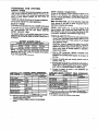
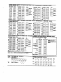
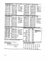
BA~ERY
BTANDBY TABLE
4140XMP AUX. STANDBY CURRENT DRAW
,AMP-HRs. 1200mA
I 400mA
I 600mA
I 750mA
4.0.
I 6hrs.
[ 4 hrs.
I 3 hrs.
[ 2.5 hm.
7.0
Illhm.
I 7 hrs,
I 5.S hrs. 14 hrs.
NOTE: The~vefigures
areapproximata,
ati mayvay
de~nding
upon the age, qua~iy, and cqictiy
of the battefy
at the lima & the AC loss.
. Uss 4AH b~aW for UL installations.
EARTH GROUND CONNECmONS
In ordar for tha tightning transient protetiiva davices in this
product to be aflatiiva,
the designated
eanh ground
terminal, must bs tarminatad in a god aadh ground. The
following ara examples of gmd aafih grounds availabla at
most installations:
Metal Qld Water Pipe: Use a non~rrosive
metal strap
ti~ly
sasured to tha pips to which tha ground laad iS
alastri~lly rnnnadad and seargd.
AC Powar Outlat
Ground:
Availabla
from 3-prong,
120VAC, pwar owlats only. To test the intagiiy of tha
ground tarminal, usa a threa-wire circuit taster whh neon
lamp inti=tom,
such as the UL-List~
Meal Modal 61-035,
or equivalent, avaibble at most eladrtii
supply storas,
POWER-UP
PROCEDURE
1. Fill OM tha PolUng Lmp Currem Draw ad Auxifia~ Deviw
Currem Draw Workshaats shown bebw. Maka sura that
tha currants drawn from these otiptis
do not exceed
their respa~ive ratings.
CAUTION: Failura to obsewa tha ~iiing loop currant
rating will cause polling loop malfuntiion.
Failure to
obseme the auxifla~ outpffl cumanl rating will result in a
battery which doss not charge proparly or posaibiy a
trippd circuti breakar.
2. ~re the 1361 transformer (1361 CN in Canada) tO the
panal (bafora mnnecting tha batte~) as shown in the
SUMMARY OF CONNECnONS diqrm.
b nd plug in at
this time.
2. Connsot all polfing loop and auxilia~ devias, such as
rnnsolas, PIRs, etc.
3. Plug the 13St into an 24 hour, unitiemupted AC otilet. In
a faw semnds, tha graan POWER LED on the rnnsoie(s)
ahouw I@ht and tha mnsola(s) ahouM display .READY.
(4127. 4137) or “DISARMED READY TO ARM” (513~,
4. bnnist
the batte~ as shown in the SUMMARY OF
~NECTIONS
disgrm.
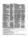
POLLING
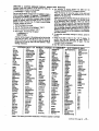
LOOP
RPM DEVICE
CURRENT DRAW WORKSHEET
CURRENT # UNITS [ TOTAL
I CUR RENT
4194 Conkd
lti
4192S0 Phob SmWe
0.4 MA
4192SOT &&
WHeat 0,4 d
4192GP 10” SmO@
0.4 d
4275 O“al PIR
lti
4278 Quad PIR
lti
41S02-Z- RPM
1MA (LOW)
2 MA (HIGH)
4208 S-20M RPM
1s d
42S0~ 20”e RF
4oti
4zw S 20W RF
4oti
J TOTAL . .
I
..
If ti M*I cuwnt &w ex~ds 64 mA, a 4197 ~
Exm*r mtiule must be usd,
..
If utiw MO 42WS or 42-s,
you -n -r
m of M
km a.xil~ pinswad of .al”g a4187 mp e~~m
&b.
-16-
~
AUXILIARY
OEVICE
14127@S~
14137GS*
DEVICE
CURRENT
DRAW WORKSHEET
I CURRENT j # UNITS I TOTAL
a, ,”----*“””en,
I
Imti
Iso@
--
I
I
,
I
!
I TOTAL
(7~ti
max)
I
. II using bti-w,re dev,~s such as PIRs, retw to ti spcifi~tions
~r Bat pticuhr univs w-t
draw.
t Only qd~s if wati
*
tiws
autil~ pwer.
i
\/
V.
--,
SECURITY
ACCESS
SYSTEM OPERATION
CODES
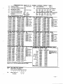
The VISTA 4140XMP System allows up to 70 s=urity
a~ess males to be assigned, each identiied by a user ID
numhr. The system al= offem either standard (4dgt)
or
hgh sm~
(6dtgti - user # + 4digts) smurfiy &es (fieti
1.S4), If H~h Securfiy mode is seleaed, the 2dgif user #
followed by the 4-digif code must be entered for all
operations (lnstaller_Ol,
Master code -02, etc.).
For
example, if user 14, whose rnde is 5676, wishes to d!sarm
the syqem, the s~uem
WOUMk 1A5+&7+8
+ OFF.
The installer pr~rams an Installer-s tie
initialy as Wn of
the programming pmcedura, and this mde is the on~ de
that permits re-ent~ into the programming mde (unless .98
h= bean previous~ used to exR the programming mode, see
bbw).
The Installers ~demnalmba
usdto
@dorm
normal system funti!ons,
but cannot assign tempora~
mdas. Note that the installers code annot
disarm the
system unless k was used to arm the system, and that if
-nnOt be used to disarm the system if the system was
amti with the QUICK ARM key [#],
h shipped from the fado~, an initial Installerns mde and
master @de k pre-programmed, and =n b changed by the
in9tallar to anv, rnde desired. The Dre-OrOarammed rndes
are as fofbw:”
Installac 4-14-0
tias~ec ~-2.3<.
The installer b rnnsierd
u<er t. The pemon to whom the
M=wr tie
is a$sign~ is mnsidered user 2. The Master
tide k the ade intended for u= by the pflma~ user of the
system when petiorming
system funofions,
and is a
Wrmanent rode. The Itioy
default master rnda is 1-2.34.
For additional secur~, the Mater tide
can k used to
-sign
up to 68 tempra~
males, which mn h used by
sernnda~ usem of the system who do not have a ned to
know the Master hde (supewisom, employees, cleaning
personnel, tenants, etc.). Each user (ID number 03-70) ~n
be assigned a tempora~ code which an be individually
elimin~d
or changed at any time.
-..
Note that the Master Code (assigned to user 2) and all
tempora~
codes can be used interchangeably
when
ptiorming
system funtiions (a system armed with a user,s
tempora~ mde mn be disarmed with the Master ~de or
another user’s tempora~ rnde), with the exception of the
Babysitter Code demri~d
later in this seotion. Temmraw
user 3 has the ability to assign and eliminate tempora~
males 04-69. User 3 cannot assiqn a mde to uwr ?0,
TEMPORARY
CODES
User 2 (master wale) can *sign and dalete all tempora~
ales,
03-70. User 3 an ~sign and delete tempra~
u~r
males 04-69, User 3 cannot assign or delete user 70’s rnde.
To add or deleta temporary
codes:
Us- 2: tister C* + CODE by + Umr # (0>70) + 44gi! User w User 3s CODE + CODE key + User # (04+9) + 4dgi!
To delete temporary
codes:
MAer Ue
+ ~DE kay + Lf-r # + Minter He
UWr numbem must be entered as 2dgit atiries. SiWle digit
usar numbers must, therefore, always b preceded by a .0”
(example, 03, 04, 05, etc.). Make sure the end user
understands !his requirement. Tha system will emti a single
beep when each temwrav
coda has been successfully
entered. H the 6digit ~de feature is in effed (field 1.54),
temwraw users must also use 6digfi males (2digit User # +
4d!git wale).
,.-.
I ~2i~r~&mf~$d
that obvious
codes, such as 1111 or
The syslem also provides an Instafler tide lock-out feature,
which prevents the use of the Inslaller’s Code from reaccessing
the Programming
mode afler the initial
programming. This feature is amivated by pressing .98 to
exit Programming
mode.
The only way to access
Programming mode once this feature is activated, is by
pwering down the s~tem and ~wefing up again, and then
pr~sing bmh the “ and # keys at the same time wthin 30
semnds of pwer up. If re.access to Programming mode
using the Installer’s tide k desired after initial programming,
then exit Programming mode by pressing .99. For additional
S=urity, the installer de
an be used to disarm the system
onfY ~ k w= used to arm the system,
The Installer alSO p~rams
the mater securtiy rode, which
is the code intended for use by the pfima~ user of the
system. The master rnde ~n then be used to assign up to
68 tem~ra~
codes (03-70), which can be used by
s-ndaw
users of the system who do not have a need to
know the master code. In addition, the Quick Arm feat”m
can also b programmd,
which enables the [#] key to be
pressed in lieu of entering the se~rty rnde when arming the
system.
The duress ade “is a means of sending a silent alarm to a
central mon”mring 6fatbn i the user is being forced to disarm
(or arm) the system under threat. This feature is only useful
if the system is annetied
to a central station. When the
system’s AuxiiiaW Voltage Triggers are conneaed
to
another communiation’s
mad[a (Derived Channei/Long
Range Radio), note that duress is signalled on the same
trigger that signals silent panic (whereas duress has its own
Unque re~n when digtil~ mmmunkated).
The duress @de is simply the usual security code, but with
the fouflh digh increased by 1. For example, i the security
de
k .t 234., tha duress de
is ‘1 235-.
When used,
the sy$!em will dtsarm (or arm), bti will also send a silent
slam to the Centrti Sation. There will be no indication at tha
rnnsola that an alarm w= sant. Nate that duress males am
nOt available for s~urity wdas ending in the digit .9-.
IMPORTANT!:
Users of temwrary
codes should be
instrudad to antar thair codas carefully, to avoid the
~ssibility of addantally
entering the duress rode.
Note: When a tempra~
rnde is inadvenently repeated for
diffarent users, or one USEVSmdo is anotharns duress ~da,
the lower user “number will take priority. Do not assign
sequential males 1 digit apafl from a=h other (ex. 4096,
4097, 4098) as this will cause a Duress to be sent each time
(one u$sts rnde k mtiher users duress code),
IMPORTANT!:
Unless Ademco Contact ID rapotiing is
usad, only user cties
#1 - #15 can uniquely repoti to the
central statbn using the mmmunicalion
formats providad.
Users #16 - #7o will rewfi as User #15, if enabled for
opnldosa
re~ning, for the other re~fling formats.
BABYSITTER
CODE (User #22)
If program field 1.50 is enabled, the code assigned to User
22 cannot ba used to dismm the system unless ths system
was armed with that rode. This code is usually assigned to
persons who may have the need to arm and disarm the
system at specific times only (ax. a babysitter needs to
control
the system
only when
babysitting).
It is
remmmandd
that tem~raw
usars, such as babysitters,
not be shown the byp=s procedure.
-17-
KEYPAD
FUNCTIONS
The keypad allo~lhe
user ti~anddisarm
the system,
ati pedorm other system fundions, such as bypassing
zones, view messages from the central station and display
zone descriptors.
Zone and system renditions
(alarm,
trouble, byp=s) are dispfayed in the Dis@ay Wtn~w,
The sy~em protides four m~es O! burgla~ proteabn:
STAY, AWAY, INSTANT, and MAXIMUM. In tidflbn, it any
zones are fauhcd ptir to amiW (NOT R~DY mndtbn), the
mn~le ccn display them one at a time, ati SPCMC zones
un be sele~ively bypamed.
When an alarm recurs, mnsole sounting
and e~ernal
sounding will uur,
md the zone(s) in dwm will h di~lsycd
on the mnmle.
Pressing sny key will $ilen@ the wnaoie
sounder for 10 semnds. Dsarming the system will silen~
bth mnmle and external soutiers.
When the sysiem is
disamed, any zones that were in an alarm wnditrnn during
the armed perbd will be displayed (memo~ of alarm]. To
clear this d!~lay, simply repeat the disarm sequence (enter
the secu~ tie
md pre~ the OFF key).
The mn~les
also feaure time annundatbn, and 3 ~ic
key pairs (for silent, audible, fire or auxiiia~ alarms) whbh
m notify the mniral stalmn of an slam mtiiion,
if that
sewice is mnnetied.
Note that if QUICK ARM is ena~acf (field .29), the [#] key an
be pre~ed inztaad of entering the s~urfiy rnde, for any of
the arming pr~dures
(Away, Shy, InSant, Mtiimum, etc.),
For ddtional
itiomation,
refer b the Users Mmual.
VIEWiNG
oowNLoADEo
MEssAGEs
5137 rnnsoies onfy.
Usars may o~sbnally
receive messages on the mnsle
dsplay fmm their installation mmpany.
When INS ~“~,
the mnmle
will display .Message. Press O for 5 se=...
Instrud the user to pre= and hold the O key m dkplay the
antral station,s message. Nde that the system must b in
the READY state @ view these mess~es,
USING THE BUILT.IN USERS GUIDE (5137 Onty)
An abbreviated User,s Manual is stored in the system’s
memo~, and an k paticular~ useful to the end user i tha
printed UsaPs Manual is not ~“veniently
a~ssible
when
the user needs to ~fiorm
a seldom “sad and u“famifiar
sysam pmmdure. The Suih+n Usets GuWe k dkplayad by
simply pressing any of the funabn keys (e.g., OFF, AWAY,
STAY, MAXIMUM, BYPASS, INSTANT, CODE, TEST,
READY, #, and CHIME) for cppmximately 5 aemnds and
then releasing it. Abbreviated instmaions ralativa ~ the key
that has ken pressed will then k displayad (2 lines of tem
are dsplayed at a time). This funaion is available when ths
sysem k in the amsd or the dls=md
ztate.
PANIC KEYS
There are three paim of keys ~ + 1], [# + 3], ~ + #]) that, if
programmed, mn be used to manual~ intiate alarms and
send a repn to the -ntral statbn. E~h pair of keys -n b
individually pr~rammed
for 24 Hour S!lent, Audible or
Auxifia~ respnses.
Tha panic funabn
is mivated when
the appmpride pair of keys are pres~
d the same time.
The panti funabns
P~a
.+1
#+3
.+#
are identified by the system ~ follows
~.
05
96
99
mnsoles,
these panic
wkh an alpha de-r.
keys
can
also
be
IMPORTANT
For the Panic fundions to b of pradiel
value, the s~tam must ~ mnnxed
to a -ntral Sation,
.
PRS AT
WE TIME
-
-
DISPLAYING
DESCRIPTORS
(51 37 only)
The Afpha tinsoles
=n display all pmgrmmed
descriptors,
which is useful to the installer whan chtirng
entties, and
=n be helpful to the user when thers is a ned to Menlw
Zonas. To display descriptors, prass and hoti the READY
key until the built-in instruaions for that key appear, then
reie~e the key. me zone de=ripom
will cppcar one at a
time, for abut 2-3 samnds each. For faster viewing, press
the READY key. to display the neti de~riptor
in numeiil
order and za on. When all deswiptom have been displayed,
the Control will exk display mods. To exit tisplay mda
before all descriptor
have been displayed,
enter the
aecu~ wde and pess the OFF key.
For 5137
pqrammd
-ls
_
TROUBLE
-.
CONDITIONS
The wrd ‘CHECK” on the Console’s display, a-mpanied
by a rapid %aeping. at the @nsole, indi~es tit there@ a
trouble mndtiion in ihe system. The audible warning sound
=n b silen-d
by pressing any key. Instrua users to call
for sewiw immediately upon saeing any of the following
massages,
“’CHEC~
MESSAGES
A display of “CHECK” ~ompanied
by a display of o“e or
mom zone desmiptor(s) (513~ or numefc zone IO(S) (4137,
4127) indimtes th~ a problem exi~s with those zone(s).
Fist, detemine ti the zone(s) displayad are intad and m~e
them so if they are not. If ;he probtem has ken mmetid,
key an OFF aequen- (Nn
PIUSOFF) to dear the d6play.
A display ti the wrd .CHECW ~mpanbd
by a numeti
dwplay of .9T indimtes that a shod axists on the Polling
LMP and m~ efiminata some & the pmtedion. Fauti W7cw b assigned analpha descriptor when using the 5137
console.
A display of the wrd ‘CHECK ~mpanied
by a numati
display of .88., “89”, .90., or .9t. indides a 4280 Receiver
problem. Fauhs .8&! ’89 ’90”& V1. m k -igned
ok
desmiptom when ustng the 5t37 mnmb.
POWER FAILURE
Mthe POWER indicator is off, md the messqa .AC LOSS”
(5137) or .NO AC. (4t37, 412~ in di~Wed, the tinmle
is
operating on batte~ Wwer on~. Che& b aae that your
system’s plu$in trandormer has ml&n
~datil~
pulled oti. Instrudthe usertomll
asetimrepresentaltie
immediately f AC Wwer ~nmt W restord.
RECALLING
~.
ALARM
& TROUBLE
A dkplay of .LO BAr (5137) or .BAr (4137, 4127) and a
zone descriptor, ammpaniad
by a onw ~r minute &ep at
the Gnwle
indiates that a low batte~ mndhion exists in
the wireless transmbter displayad. The audible warning
sound may be silenced by pressing any key. A d!splay of
.sYSTEM LO BAT (5137) or ‘BAr wfih “o zone 10 (4137,
4127) indi~tas that a bw batte~ rnndfwn exists with the
system’s ba~up batte~.
A display of ‘428o SETUP ERROR- (5137) or “Ew (4137,
4127) at the mnsole indties
that a 4280-8 re-iver is being
usadina syaemwhh more than SRFzone$pmgrammed,
If
thw is net rnrraded, none of the zones in the systam will be
p~edti.
If more lhan 8 RFmnes
are desired, a 42S0
R-tier
mmt b used.
A dii@ay of .MOOEM COW (5137) or “CC. [4137, 4127)
indmtes that the rnntml is on-tine with the remote mmp”ter
ati the mntrol is nol oper~ing.
A dbplay of Iwo numbers and .NO AN (all keypads)
ind~tes the rnntrol is in the programming mode and is noi
operating.
MESSAGES
The system’s alarm memoy retains all events for a parti of
10 days, staning a the time of the first event. Upon
expiration of the 10day period, all fdsov is amomatially
eras~ and the slam memoy will reset. The neti 10day
qde will begin whan the neti event am.
Re-11 by sewim personnel will diapfay all events that have
occurred fmm the stafl of the 10day wcle to the time of
r-n.
Note that R~ll
will and any 10day ~b
in p~rass,
Tha LCD display on the 4127/4137 rnnsob will indi~te the
numbr of the zone in whbh the event tiumed
(e.g., 01, 02,
etc.), a-mpanied
bY tha word CHECK (tmubb), ALARM
and, If apphable, FIRE, to dasctib the ty~ of event that
wuned
in the tiapfayed zona.
.
ING iHt RkAL~t
?hereal-time CIOA must b sat before
OTHER TROUBLE
CONDITIONS
A dspl~ of ‘cOMM. FAILURE- (513~ or T@ (4137, 4t 2~ at
the Console indidas that a failura mrrd
in the telephone
=mmun&tion
pmtion of your system.
(Memory
of Alarm)
ff a 5137 is used, n alpha descriptor of the zone will h
displayd
in addition to ffs zone number. ff more than one
event had muned, the events will be dis@ayti in numerical
saqueme. Each dkpiay will ap~ar for t-2 aemnds, than the
neti event will be display ad. When all events have bean
dbplayti.
the dkplays are ra~atd.
To display 10day histo~,
enter the securty mde and
pre= tha O key. Note that ra=ll will end any t Oday wde in
pmgre-.
To exit Mmll mods, anter the security -de
and press
Iha OFF kay. All axisting history is erased and the alarm
mamoy k raaat. The 10day qcie will San again only when
the nefi went ~rs.
CLOCK
tea reW~ w &
sent. Be sure to set the FIRST EST REPORT TIME in
program fiald “U, and the test re~ti intawal in fieti .27. To
set the cfock, a 5137 consob must be conneaed to the
panel.
TO -t the day, use the [3] or [1] key to change from ?
ON to MON to TUE. dC.
To sat the time, press [6] until the .?. appears in the
... - ,-,
hours position, than --11.e ~hn
f~l n,
.e~ ~k-. rll
, ., kow
..-, tn
.- .-.
. . h“,,,
..””. .
Prss [6] again and use the [3] or [1] kay to set the minuta,
10 enter real-time
clock mods, press CODE + #63. The use the [~ kay tO sat AM Or pM.
display will show
TIMErOATE
? ON
To set the data, press tha [6] key until the .?. appaars in
the month wshion, then uaa the [3] or [1] key to sat the
olmtso
12:01 AM
month. Press the [6] key again and use tha [3] or [1] key to
Tha’?
lntiates
the current mode. The [6] key changas the
set the date. Press the [6] key again and use the [3] or [1]
mode from OAY to HOUR to MINUTE to MONTH to OAR to
key to set to set tha year.
YEAR. The 14] key changes the retie in raverse order.
TO exit clock mods, press aither the [81 key or the ~]
The [3] & [1] keys are used to set the TIMErOATE values.
kay. =iting with the [8] key will save all changes. Exiting
The [3] key moves the TIM~ATE
ahead, the [1] kay moves
w~h the k] key will exit without changing any of the values
the TIMWOA~ bac~ard.
(used whan viawing the time settings, bti no changes are
desired).
-19-
V1.
SYSTEM
COMMUNICATION
SPLIT/DUAL
REPORTING
Dual repofiing ~51 ) sends all repons to Mh ptima~ and
semnday phone numbm. Splti repofling allmya repns to
k dividd ktween
the phone numbrs
-rding
to the
fields
(1.34) seleaions.
SpfiUDual reptiing
can be
seletied by entikng dual re~fling and entiling one of the
spit repmting options in fm~ 1.34. K O@iOn [1] k salemti,
all akrms, slam reaores and a=l
remm will go ~ kth
phone numkrs,
while all other re~ms will go to the
sandav
phone numkr. H [2] b selaad,
Opnblose and
test messagw will go m @th phone numbwa, while all other
rewfis will go to the primphone numhr.
ADEMCO LOW SPEED
ADEMCO LOW SPEED @ a Dubd fomai Mnh resmnds to
a 1400 W handshake and ti~-ff,
end tmnsmtis data wtih
1900Hz puke @nes @ 10 Pub- pr samnd (ws). A fypb61
message mnsists of two rounds which mud be ver~ed by
the receiver, A mmplete standad repfi mnsis@ of ether a
3 or 4d]gti a-unt
num~r Iolbwed by a 1digh al-m rode.
Even though 2 rounds are sam, only the valid rewn is
dnplayed on tha reaiver.
In expanded repfling,
w
messages are sam, two rounds
per message, the first being the a~um
numbw and atim
rode, tha sewnd king the zone ID rnde b which the alarm
was ~signad.
A mmpbte expatied ra~fl mnsiss of a 3 or
4dgfi munf
numbr followad by a 1digt slam de,
then
the slam mda is repeated, folbwed by tha channel numbr.
=.Stibti
CCCC E
CCCC. _whr
E~
~
EE
EE. ewnt d
EEEE ~
Z-~lDa
SESCOAIRADIONICS
Standard
and
expanded
raporting
in
the
SESCOAfRADIONICS
format is vinually the same ~
ADEM~
bw Sped exept for tha following:
1. ma handshake and ki~~ff frequen~ k 23OO k.
2. The d~a n transmitted wkh 1800 Hz pulm tonas.
3. The rate of transmisbn
k 20 pw.
4+2 REPORTING
A 42re~ti
mnsists of a 4dgif amount number and a 2.
dlgif alarm code, or event ~da.
42
repons can be
acmmpfishad either in ADEMCO Low SPd
(1 O pps), or
SESCOWIONICS
(20 ppS) f0n6t.
In 42
re~ning
a unique 2digit code for each zone is
re~tied. A 4dgk a~uti
numkr fofzowed by a 2d\gft de
is sent, where tha first digfi is the actual event, such as in
ALARM, RESTORE, or TROUSLE, etc., and the sarnnd dgif
of the rndo represents the zone- where the event oarred.
(b~ not necessarily tha aaual zone numbr). Each mda in
tiseti is uniqua to a s~cific zone. A typbl mpon fol~
1 234
59 ~5 Y might ~ a uniw ~~
~=W,Zw
25).
4+2 EXPRESS
ADEMCOS
new Exprass format provides
the same
information as the 62 format, bti with three dflerenrnx
1. Data is transmitted in OTMF (Dual Tone Muti-Freauenw,
known as VouchTone.,
at the rate of 10 charaabrs per
s-rid).
TtiIs greatly decreases the time h t~es a repn
to reach the central st~ion. An average 42 Low SWed
repfi might take as long as 20 semnds to complete its
repn, bti &2 Express t~es under 3 sernnds.
2. Two message rounds are eliminated by the use of a
tiecksum digit. Instead of the rnmmuni=tor
sending 2
rounds per re~n, it sends onk 1 round wkh a che~sum
digit at the and. Doing this aba helps in decreasing the
time it takes for a repon to be sent. (CHECKSUM is
expkainad fufiher at the end of this Sedion).
is 1400 Hz followed by 23oO
3. The handshake frequenv
Hz. and the kissoff fiaauati
is 1400 Hz.
,,
-20’-
ADEMcO
HIGH SPEED REPORTING
~EM~s
Hgh Sped format transmtis data in OTMF at a
rae of 10 tiaratiers
pw semnd. The handshake frequan~
is 1400 * folbwd
by 2300 Hz, and the kisoff frequen~ k
1400 Hz. The message mntains 13 digits as folbw
A 4digh a~unt
numbar + e~ht channels of zone information
(l-8- or duress plus 9-15) + one status channel, which
idemifies the w
of events king rapnti
in tha eight zone
I-tions.
A typi=i High Sped rewti will h kissed off in
under 5 s-rids.
W
-
l.mwm
2. OPENING
,.
3.W m’
4. CL=ING (S~ms CWnMl ~~S - 4~
5. NWMNTOREWT
6= P~OUSLY
REPoRTED. NOTH RESTOREO1
“ NO-:
Channal 1 will rnntain the user ID ;-9, A-F if
OWn/Cbse rewning is enabled.
The swtus channal might hava the following rnndtiions:
1- DURESS(%r DuressPlus CWmls S15 Gly)
2. WENING
3- BW~
(% Ctimls
14 ~k)
4- CGING
5= TRWBLE (FM Cbmls
14 my)
6= ~M
STA~S
.ACL-n*Al
. LOW BA_RY in **
2
. PROGRAMTAMPERm C-9
.~Of4RES27in
C4
7- ~WWW
STAWS (Fw ~~
1+ tity)
9.T5sT~
repfi may Iwk as folfow
A fypbl hgh s-d
1234511555557
(M#1234
w~h alamson timnek
2 & 3)
.,.
ADEMCO
HIGH SPEED LIMITATIONS
1. When using Ademm hgh s-,
remambr tham ara on~
15 channels available, plus a duress channel. If more
than 15 zones are tiIW used, they mu~ share channels.
2. Wfih high s~ed mpoting, channala 9-15 @nnot repon
tmublas or byp~ses. Use thase channels for zones that
wilf not have to repn these renditions.
_
CONTACT
10 REPORTfNG
~S k the only format that -n identtiy all M pmte~ion zo”as
by their unque mne (~maa)
ID numkr$, and pmvties a 1digit evem qualtiier and 3digit, s~cifically
defined evant
mde.whkh qud~
identifies the ra~ned rendition.
Comad ID rep~
in DTMF mud Tone Muiti-Fmquenq @ 10
chartiem
~r s~nd)
and respnds to a 1400 Hz foflowad
by 2300 Hz handshaka, and a 1400 Hz kissoff. Tfds format
also uses chetisum instead of tw message vwificatbn. A
mmpleto repoti ties
under 3 ~nds.
Coma
whara:
a
QEEE=
G&
z=
l~wQfi~~~
following fomz
CuSomer (sub=ribr)
numkr.
bent quarfiar, where: E-new evem (1) am Rreatore (3)
Ewnt de
(3 hexad~mal
digRs), dafind in the
t~le on the next Baae.
Atiays 00.
hnelrnntti
ID numhr raw fling the slam (001 099), or user number (001-070) for openlclose
repns.
System st~us messages [AC Loss, Walk
Test, etc.) mntain zeroes in the ~
Imation.
.._,
TABLE
,..
Codcl
110
121
122
123
131
132
133
134
135
142
143
150
301
302
305
306
309
332
Defl”ltlo”
I Fire Alam
Duress
Silent Panb
Audible Pa”i=
Perimeter B“~law
Intetior B“mlaw
24 Hour Buwlaw
Ent~Exit B“rgIav
Dav/Night Buqlav
POlfinq Lwp Shofl Ala~
RF R-tier
Failur~Aiam
24 Hour Auxiliaw
AC Loss
LOWSystem Batte~
SVstem Reset
Pmgmm Tamper
Battew Test Fail
Poll Lmp Shofi-Trouble
OF CONTAC :T ID EVENT
~Codal
333
373
38o
381
382
401
403
..4-
409
411
570
601
602
CODES
Daflnltl Ilon
f Rmn ber Failur*Tmuble
RF
R
f ire bop Tmubla
—
Trouble (global)
bss of Supen
I-RF
1
wision
jc
IF
3r
nsmtier bw BaneV
User
m (Download)
n
H
7 Olc
c
-.. .-. -”-.. d
e..
;
Manually Triggered Test
Periodic Test
ADVISORY
Ademco,s new Contaa lDre~tiing
ismpableof
uniquely reponing ali Wzonesof
infomation, aswellas
openings and
closings !or all 70 users, tocentmlstatbns
equipped with the Ademrn 685 remtier using software level 4.4 or higher. 685
s0har9 levels below 4.4~nnotsup~fl
Contad ID repding. Forinfomatbn
regarding u@atingtha 68s ,aceiver, ~“tati
Ademm,s Techni~l SupPn group a 1-EM-645.7492.
4140XMP
Field
“46, .48
#
.52, .53
<..
.79, .8o
.49
.81, ’82
.64,
.61,
. 69,
. 76
. 55,
. 62,
. 70,
. 77
.58,
. 73,
“56, .59,
“64, .66,
“71 , .74,
COMMUNICATION
LOW Speed
Chwse transmissb”
sped and frwuenW
Send = efiher 42
or expandd
Enables slam restores
Add checksum digi
Define -es
a“d
sel~s 41 or *2
Defines alarm event
rnde
Contact
No effeti
PROGRAMMING
ID
High
No effti
Speed
No effed
No elted
EnXles slam rasto,es
No effed
181digit enables raWn
f k is non-zero
EnMes re~ns
Enables slam restores
Add checksum diqt
IS digk enables re~fi
ti if is non.zerO
~gns
reWfli”g tinl
for all rewns fmm this
mne. EnMes aIa~
rewtiing
No eff~
Enables alarm restores
No effed
~“d
Define des
seltis 41 or 42
Defines alarm evant
rnde
Defines rnde and
selws 41 or 42
No effed
.63, .66,
.78
EnAles re~d and
s ele~s rnde. Note:
N0 restores f
event not sent.
Entiles
s escotiRadionics;
s eleds freed digti time
instead of fhed
interdigit.
NOtO: Low SW4 will
n ot send 3+2
m esages.
Zone ID
digit is suppressed.
No effea
N0 elted
Note: h ~ntati
ID is
d-ird,
it mus &
used on &h ptimay &
semndaV phone #s.
n High Speed is used
fo r sewndaV, h must
b u~d for prima~. ff
used on prima~, any
01her format Wn be
used on semnda~.
NOTES
Express
No effea
No effeti
.57, .6o
.65, .67,
.72, .75,
.5 0
GUIDE
repti
EnXles re~n
N~e Alam tia””eI
must h prqrammed.
(01 -15)
Defines mde and
Sel*s 41 or&2
En*les re~n and
seleti Ist digit of. the
2~gk event rode.
NOTE: No restores
H event not sent,
N0 effaa
-21-
V1l.
GENERAL
PROGRAMMING
PROGRAMMING
PROCEDURES
The system is shippd with a set of pre-p~rmmed
values
that are designed to meet the needs of many installations.
These an b changed by the installer to suti a~ctic ne~s
In addition, Iour sefa of preprogrammed
if desired.
rnmmuni=tfon
dafauff values ~n al= ti Ioadad by the
installer. aach sat deaionad for a sDwific mmmuni~tk
format. These too =n ‘be changed ‘to suit the needs of a
~tiicular
installation.
Changas
to thase pre-programmed
valuas can ba
programmd
dirati~ from the ansole or fmm a mmpmer
terminal using tha 4130PC Domloading
=tiara
(be sura
that the software vemion uaad includes a 4140XMP menu
aeledion), an IBM rnmpatible mmptier
ad a HAKS 1200
SMARTMODEM. The Iollowing pwagraphs deamibs how to
load the various default programming sets. For datailed
in~rutilons
on making changes to panbular programming
fields, refer to the programming sheet at the end of this
manuaf.
For alpha consolas, English
zonas and a wstom insallar
tha systam is ready IO arm)
buill-in voctiulay
of words
DESCRIPTfONS p~ag~hs
THE SYSTEM
Language descriptions of the
messWe (which ~~am
when
-n be programmed using the
(see PROGRAMMING ZONE
Iatar in ttis sedion).
DEFAULT
PROGRAMMING
There are five sats of pre-programmW
defauffs available
(one standard, plus four dtierent mmmuni=tion
defaults).
Any one of thasa an be Iotied into the system’s memo~.
Refar to the COMMUNICATION DEFAULT PR~RAMMING
satiion for instrutiions.
DATA PRoGRAMMING
The programming
fields ara grouped into lwo sets of
addrasses. Tha first set is ameswd ~ s~n ~ pmgrammi”g
mode is antarad. To a~ess the second set of addrasses
flndi~ted On the Prog~mming fom by a .1” in front of the 2dqfi field addrass), press .94 wtrila in programming mode,
then press ~] plus the fimt fiald numhr desirad. Note that the
alpha mnmlas dkplW the wrds ALT PROGRAM MODE, and
the 4137/4127 mnsoias tisplay the Wd CHECK to indimte
thesmnd
sat of addressas.
To ratum tothafimt
set of
addrasas,
prass “99, then press ~] plus the fiald numbar
dasired.
To program
apeclfic
data flelda, prass~]
plus the2dgfifield address, thenmakatha
required ent~. Themnsofe
will Wep whan a fiati h= Men wmplete~ programmed and
will awomatimlly d~play the nexfiald
in numerical order. If
the number of digits lhat you anter in the data field is less
than the maximum permitted (for axample, phona number),
thew”sele
displays the last enty and waits. To proceed,
the next data field address to be programmed must be
entered manud~ (for axampla, press .05).
10 viaw the contents
of a data field, press [#] plus
the2dg~field
address. Tbfiati
senttie swill
bdisplayed,
bw no changes to these entries -n k mada.
In case of errors: If an addreas is improperly entered,
tha mnsola will dsplay FC. f a pr~ram entW is impmperiy
emerti
(for axample, a lamer number than that which is
Wmittd),
thewnsole
display will go blank. Inatharcasa,
simp~ ra+nter the MWX numb;.
To exit programming
mods, press ahher .98 or “99.
Use .98 to prevant ra-=-ss
to programming mods by
inataflermde
method. .99 allows inmallar mde a~ass to
p~rammi~
mode.
PROGRAMMING
STEPS
1. Enter Programming
ProgmmmiW retie an k
mode
anter-
in ma of W w~.
1) Prass both the ~] and [#] keys a! the same time within 30
semndsafter Wwerisappfiad
totb~ntrol.
OR
2) Kay the insallar rode, folbwed by de~assion of CODE [8]
+ 0 + O keys. The famo~ installer mde -n k timgad
OM
in the prWram mode.
Immadiataly following ent~ into the program mode, the
follwing will ba displayad on a 5137:
-gmm
Mtie
~e4127/4137mn~las
display 00) ‘Rll#Viw
.00
Foiloting
the above display, tha system is ready 10 be
programmed forthernmmuni~tion
format parameters, or
amept data entrias. To begin data antties, prs~ ~] PIUSthe
fimt field numbr desired.
2. Sat Standard
Defaults
Once the Programming mods is antered, clear the system’s
memoyby pressing .97. This ensures all Wogramfialds are
sattotheir
faato~ set, pre.pmgrammed
valuas. if desirad,
load one of the mmmunicatbn
dafauh p~ramming
sats by
antering one of the folbwing de
squen~s
-22-
Rder b tha PROGRAMMING COMMUNICATION DEFAULTS
setiion
for futihar
instrutiions
if ona of the four
Wmmunimtrnn defauh programming sets is used.
3. Program the data fields
Program the appropriate
phone numbers and account
numb=, as well as any othar pr~ramming fields raquired to
customize tha system to the needs of the installation. Refer
to tha PRoGMMMING
FORM at t~ end of this manual,
4. Enter Zone Descriptions
(5137 only)
Refer to the PR~RAMMING
ZONE DESCRIPTIONS sedion
to anter zone desmiptom and a Wstom installar’s message.
5. Exit Programming
Mode
When all fialds have been entered and checked, and zone
descriptors have bean assigned, exit programming mode by
pr~sing efiher .98 or “99. A s-rid
entV of .99 is r~uired if
theaxit is beinodonefmm
fields 1.00 anddove.
Toprevem
ra.awessto
Programming mode using the Installer’s code,
use “98. Tha on~ way to re-a-ss
Programming mode is by
depressing both Ihe ~] and [#] keys at tha same time wkhin
30sernnds ofpower up. fitingby
using .99 always allows
reant~ into Programming mode using the Installar,s code,
Efiher way of exiting w;II allow amss via downloading.
COMMUNICATION
,-<
DEFAULT
PROGRAMMING
To ~
exwdte the in~llatiin,
Ade~
h= inmpmd
4
different mmm”ni~tion
defauhs in the VISTA XMp ~tml
(Low S~ed,
Ademrn Express, Adamm High Speed &
Ademm’s new ~nt~
ID). These defauks atiomati~lly
program indust~standard
coda assignments for zones,
keypad panim. non-tiarm and supswiw~
mndtions, and
can bs loaded at any time wtihouf
affetirng
nonmmmuntitbn
p~ram fielh.
Using these defaub saves p~ramming
timel After loading
Ono of the mmmu”htio”
detauhs, PU only “ed ti wire the
devices to their appropriate
zones, and program the
followi~:
. Gntral
swbn
. Sub~ribrs
. ~ne
@
phone numbr(s),
~unt
re~nses,
. Dakys, fimeow,
fieMs .33 & .34
numbsr(s), fields .32 & “90
fbtis
.02-.05 & 1.01-1.05
and miwellanmus
mntml optbns
me s~tem is then ~fationai.
fie p~ram
fields that are affmted by bading one of the
ammuni~tion
de fauks are fields .45 -.82. Defauh values
for e~h communi~tion
dafauk ~e tisted on the Pges
foibwing the Pmgrmming Fom at the end of Wi mmua.
For dataibd information tiout re~ning
SYSTEM ~MMUNICA~ON
Mun.
<..
formx,
sea the
EASY-TO-PROGRAM
COMMUNICATION
FIELDS
The VISTA XMP p~rmming
=Wme eliminates the nb
pr~mm zones to channels, and then channels to mtfes. ff
programming wmmunitiion
fields manually, simply enter
whatever wde (-l,
41, 42 or Ademrn ~press) is to h
sent for eati zone flncluding panbs, non-alarm des
and
su~wiso~
d~).
NO~.
Etier .1 w to tra”smfi a“ ‘A.,
wh~h -am
x .0. at the r~tier.
All zones am separated into groups of 8, with mmmon
re~re,
trouble and by~ss males for eve~ 2 groups (16
zones). There are 2 doubled~t
etiries for e=h rode. For
3+1, 41, 42 and Ademrn ~press, the fi~ ent~ is the
alarm de for a standad re~ti
The ssmnd eMW b the ID
digit for an axpandti
%1 or 61 repn, or for a &Z Or
Ademm &pmss re~n.
ff the S-rid
dgt b O, only %1 or
41 (or 41 express) nonaxpandti
messages will be sent.
H only three digfis are entered in the -unt
numhr fieti,
the ID or smnd dgh are ignorti, if enter~.
For Ademm
Hiih Spssd format, the first digit entv is the channel
assignment for that zone, and the sand
tigff k ignod,
i
entersd. For Cent@ ID re~tiing,
the fimt dgh ent~ (any
non zero ent~) en~les
re~fling
for that zone, and the
semti dgh is ignorsd.
LOW SPEED ~94*80)
Lmdi~ this def mk does the following:
. Sel@s bw sped, standard format wkh no ch~um,
kth ~ne
numbm.
. ~sgns tha folbwing repfl males:
~ for zones 247
01 for zones 1 & 4S-55 (fire zones)
02 for zones 62,63 (panic transmitted), & 95,96,99
Keypad WniG)
@ for dl ahm re~ores
. Eneblos all zone typ retior=.
for
ADEMCO
SXPRESS
(.94.81)
bading this def~k does the following:.
. Selms Ademm express repding fomat, wtih ch-um,
for bth phone numbm.
. RePn males for zones 1-U, 4280s and keypad pani~
are seti s their resptiive
zona ID numkrs (01-64, 86.
91, 95-99), Duress is sent= .DD.. Alarm rasmre & .E. +
sand
digk.
. En@les all zone fyw redor~.
ADEMCO
HIGH SPEEO ~94*62)
Lo~lng thb defwff does the following
. Sel~
Ademm Kah Sped fomaL wih m ch~um,
for
Mh ~one numbm.
. Repning k -ignsd
to the folbwing chsnnels
~annel 1 for mms 1 & mn- 4SS (Fire mn~)
Wannel 2 for zones 2-6
~annel 3 for zones %16
~annel 4 for zones 17-31
tiannel 5 for ZOMS s247 (RF intetir zones)
timnel
6 for mne 56%1 &84
tiannel 9 for ~nes62863
(pmb transmtier)
tim~l
7 fm ~ti
4280 (86 & 89) & PI ~
sham (9~
Mannel S for fi~ 426o (90 &91)
tianneb
10, 11 &12 for ke~”
panis 95,96 & 99
ra=etiivab
. . . . . . .. . . ..
. Ensbles all zone fy~ remor-.
. Ensbbs Dura= to k wti.
CONTACT
ID ~94*83)
bading this def~k does the following
. %1GID fomat for kth phone numbrs.
. ReptiW
is entiled for all zonm.
. Enbbs all zone ~
retioras.
. Refer@ the SYSEM -MUNICAnON
s-ion
for event
de
definitions.
NO~:
Restoral repfls for an event wIII not k sent if the
eveti kseff is not enabled, even if a restora code is
p~rammed
for that evam.
,,...
-23-
PROGRAMMING
ZONE DESCRIPTIONS
ffU$ing
85137WnS016, a user friendly Eng~sh languWe de~r~infi~tio”
of alI pmtm~”
zones, key~d psnb, pollng
bp
shod and 4280 Suxwision
fauhs can be programmed into the system. Each de~iption
can k mm~sed
of a
rnmbination of wrds (up to a maximum of 3) that are seietid
fmm a m~ula~
of ~mximately
22o words stored in
Wrds
~“
k addd
to those
memo~, and MY mrd an have an “s. or. ,s. Wd
to it. In addibn, w ~ 20 installer~afi”ed
already
in memo~.
Thus, when an slam
or troubb murs
in a zone, an ~mpri~e
desc~on
for the ktion
of that zone will
b displayed at the mnsob. An instillers mes~ge mn ako b p~rammed
whkh will h displayed when the system is
‘Ready. (ax. WE PETERSONS). NOE
Afpha d~r@or
ant~ an b aam~ihd
hl~
at the 5137 rnnwle or remotely
udm a4130PC Dmnbder.
ENTERING
ZONE
t. Enter pr~ramming
2. Key .93. The fol~ing
OESCRIPTIONS
m~e = dtiri~
wfll b d~l~~:.
prevbusly.
ZN ??
In ttis rode, the rn”wh
keys have these fu”~ion=
[3] Scrolls Mh alphsbet and aaual wrds in a~nding
dphabtkal
order.
[1] Scrolls kth alphsbet and aaual wrds in des-nding
Aphakthl
order.
[2] Atis or remwes a .s” or. IS. m avtiuk~
wd.
[6] Toggles beWeen alphaht and aaual wd
fist, and
used to ampt desird etiries,
[8] Saves the zone description in the sysem-s memmy.
[#] # plus zone number will display the de~ription
for
that zone.
the fimt btter of the desird de~tiptbn
(n&e that
4. Se.A. is already display~). Use key [3] to adnn~
Ihmugh
the alphabet and key [1] to go batiwati.
For example,
assume the desirad description for zone 1 b BACK
D~R.
Press key [3] re~ated~
(or hoM down the key)
until .W ap~ars, then press key [6]. to display the fimt
available wrd ~nni~
with S. Re~sfd~
Pass key [3]
to advanm through the avaibble words until ths word
BACK is displayed. Press key [1] to move b~kward
through the wti
ust
To add an .s. or . ‘s ., press the [2] key. The first
depression adds en .s., the sernti
deprassbn adds an .
‘a ., lhe third dapressron displays no charmer
(tO *rasa
the ctiader),
fhe foutih depression adds an .s-, em.
To ~pt
the chosen word, press the [6] key, whbh
tW91es ba
to the afpha~t 1s!.
For sele~ion of the neti word (DOOR), repsat step 4, bti
press key [3] until the desir~ fimt letter of the na~ wod
appears (in this example, .D.). Then press key [6] to
display the fiml avail~le wrd winning
with .D.. Press
key [3] re~atedly
until the desired word (DOOR)
a~ars.
TO empt
the wrd. press the [6] key, which
Waln t~glm b~ to the alph~t
fi~.
NOTE: When programming descriptors for zones 95-99
(panics and poll shon), the following numbrs
must be
entered in lace of the ~mes
ndin zone numbsr.
-5
3. Key .01 to begin enteting She description for zone 1, (key
.02 for zone 2, “03 for zone 3 etc.). The folbwing will bs
ti~layed:.
ZN 01 A
Note that the fimt bffer of the alph~t
spWam after the
zone numbr, and that the zone number is atimati~l~
imluded wtih the pmpsti
desa~mn.
8. When all desired wotis have hen enterd, press key [8]
to Sore the description in memmy.
7. To review the zone de=riptions,
key [#] plus zone numkr
(e.g., #01 ). To edti zone de=ripfions,
numbr (9.0.,
.Ot )
.-.
9. To exk the zone d~fion
AOOING CUSTOM WORDS
Up to 20 installardefined
wotis an b addti ~ the bui~-in
v~abula~.
Each of the 20 “words. -n adually rnnsist of
several words, bm kar
in mind that a m~imum
of 10
charadem -n be US* for each word string. To meate the
cu=om word or wti string, pmead ~ follow
1. Enter the pmgrmming
5.
4,
Key the number of the custom word or woti sting to h
created (01 -20). For example, if you are creating the first
word (or word string), enter 01; when creating the second
word, enter 02, and so on. A cursor will now apWar at the
&ginning of the ~rnnd line.
-24-
(C.ntl.wd
0. P.O. 251
key “99.
Use the 131 k ey to advanca through the alphabet
(numbers,
symbols
and special
charatiars
are
included). Use the [1] key to mova ba~ through the
abh~et.
6.
When you have reached the desired charaaar, press
fhe [6] key to seled if. The cursor will then move to the
r~ht, in @sitbn for tha neti tiarader.
7.
Repeat steps 5 and 6 to create the desired wrd (or
words). Note that the [4] key ~n be used to move the
wmor to the left if nassaw,
and that key [fl Mn bs
used to enter a blank (or to erase m exkting charaaer),
Each wrd or wod string mnnot ax-cd tO charaders.
8.
Press the [8] key m save the custom word(s) and return
to the . ED ?? display. The custom wrd (or string of
added
to the
built-in
words) will be automatically
In this mode, the keys petiorm the following funtib”s:
[3] Advanms through alphabt in asmnding order.
[1] Advanms through alphatit in deswndlng order.
[6] Sele&s the desired letter, and moves the tumor to
the right one spree.
[4] Moves the cursor one spaw to the left.
[7] Insefls a spaat tha cursor Imation, erasing any
tiamtier
at that titbn.
[8] Saves the new wod in the systems memo~.
[.1 Relurns .to dewriptbn ent~ mode,
rode,
-
key ~] plus zone
IMPORTANT:
Custom words must begin with an
atph~tk
charamer. H numbrs or SymkIS we “~ad ~
the fimt charaer,
the word will not be sati.
rode.
2. Key .93. The followiW will b displayd:
“ ZN ??
3. Now key 00 to get into the mode which will allow the
custom words to ba created. The following will be
dkplayed:.
ED ??
-’
v=tiula~
at the
with the same
9.
end
of the
group
of words
kginning
letter.
ReWat steps 4 through 8 to create up to 19 addtbnal
custom words (or wod sttings).
10. Press ths ~] key to return to the .ZN ?? display, and
follow the zone dosctiption entv promdure
new words to a zone descriptbn.
11. Key “99 to exit the zone
descripthn
to assign the
programmi~
retie.
.,_,,.
1.50
BABYS~R
1.W
HGH SFCIIR~
ASSIGN
~DE
m=
❑
n
—
I-[M*.
. . . .. . .
I,[h
.
SS) 1.45
_e”
❑
ENABLE CONSOLE
1-:
A
XT DELAY
RE!
,. h-”
RF~W~R
6A~RY
LOW
wti]
h., -...,
❑
I-:
REPoRT ENABLE tith
RF RECEIVER SUPERVISION
CHECK-IN INTERVAL 02.1s ti~s
m--m[,]
RF TRANsM~R
[Mu.]
.!. h UL
❑
2k
k.w(,*~*uL
n
SOUNDER
OPTIONS
.13
WM
SOUNDER DURA~
01-T5-2
M[M]. W4m~ 4-
.16
~FIRMA~
l-w
[M*]
.21
DISABLE FRE nMEOUT
MULnPLS ALARMS
1.47
ENASLECHIMEANNUN.
ON ~RNAL
AC
LOSS
W
❑
❑
❑
AC POWR
LOSS WNDING
.18
AC POWR
LOSS ALARM
.19
ACRAN~M~
.28
POWER UP IN PREVDUS STATS
.30
1-TtiT~
1“33
.=
.34
.42
.43
.4
.46
.47
.4s
.49
“50
1.52
.3
.36
.37
.44
❑
1~e
& COMMUNICATOR
TOUCH.TONE m
[~1
[~ti
ti-]
ROTARY DM
OP~ONS
.83
[1-tI_[_]
MISCELLANEOUS
.14
OPTIONS
LINE
1-x
TIMER
“27
SOUNDER
.17
PHONE
❑
OF ARMING DING
.23
TEST
.26
~
tiUL.
❑
❑
I*,-,
.3’
I**I
.41
lW
m.; [m]
❑
[lxh~
.I.tiu
1“46
SYSTEM
.31
‘NH””BwMs~Az~E
0141: [m #til mw
AUXIL~Y
[-M
tit
CODE
I*W-IVMW
m
m k ~
(exmf Fimz-j
EOLR DISMLE mnss
[lACXJ
MmR~
PABX AUESS
~,&F(11.,5)
❑
ZONEg FAST~LOWRESp.
❑
❑
2-8)
whvww
WTPUT
ENASLE
lqdm
mm
OPTIONS
❑
OPnONS
mmmml
2-.
md~
.,.-.
ALARM REPORT CODE & ID DIGITS
[AN rndes defauh b 00]
.S4 ~DE
.55 ID
.% ~E
.57 ID
.-—
—
——
FOR ZONES
.58
.~~16111\lj
AURM
,.,, --.–.
REPORT
. ,
CODE
..
& ID DIGITS
FOR ZONES
1-33 & SUPERVISORY
.59 ~DE
“60 ID
& RESTORE
.61 CODE
24111111
32~~
3344 & SUPERVISOR
&
COOES
.62 ID
❑ FSTfiUC
.63
Pmn=e
I
NOTES 97. I
sbmls, 89 & 91- RCVRml ms~dng,
M
mn. b ~.
-----L
ZONE TYPE RESTORE
1=en~le; [O-disable]
.79
ZONETVPES 14
ENASLES
.3gpppgPPPP
Oppppqnp
.6o
OPEN/CLOSE
REPORT ENABLES
1-etilq
&disable [User 1 entiled]
.40pgoggnDn
‘mEmE’g’lo
PQ
l.ooggpqg~fi”
22
n70
.
PROGRAMMING
COMMANOS
. Toenter
program mode, enter installer wde+[8]+[O]+
[O]
. 10 set standard
defaults,
press .97
. To -I communlatlon
defaults, press .94+ oneofthe
folbwing: -80-bwsWed;
High Spee@ .83.Ademm,s
~ntm
ID
. To change to next set of program
fields, press ’94
. To return 10 previous
set of fields, press .99
. To erase account & phone number field entries, press ~]+ field number+
. To assign zone de~riptors,
press .93 + zone numkr
. Toaddcustom
words, press .93+ OO+word number (l-20)
Massage, press .93 + 00+ 00
. To enter Installer’s
mode,
press .99 0R.98:-99albws
re-a=ess
ioprogramming
. Toexkprogram
access
to pmqramming
mode
by installer
code,
.81-Adema
Express; .82_ Ademm
~]
mtiebyinstaller
rnde.
.98preventsre-
1
I
CREATING A CUSTOM MESSAGE
DISPLAY (INSTALLERS
MESSAGE)
Normally, when the system is in the disarmed st~e, the
to replace
READY
TO ARM
with the
5. For example,
folbwing display is present on the tinmle.
me~age SERVICE:42441 77, pr~d
as Iolbw
. . ..DISARMP
RWYTOARM
Press the [6] key to move the cursor to the tight, and
Pan or all of the akve mes=ga @n b modfmd to create a
rnntinue until the cursor is ~sitioned
over the first
custom installer message. For example, .-. DISARMED . . . .
I-tbn
on tk sand
line.
on the first tine or READY TO ARM on the s-rid
line MUH
Press the [3] key to advana through the aiphabt to the
be raplac~
by the instalbtion mmpany name or phone
fimt desird charader on this use, .S.). Use the [1] key
numbr for sewke. Note tha there are only 16 charaoter
to go backward, when n~essa~.
When the desired
spaces on eah of the NO tines. To create a custom display
pre~ [6]. The curmr will then move
shar~er
k reach~,
massage, p-d
u fOllOw
to the nefi Pstiion, ready for entW of the neti charaaer
1. Enter the pmgrmming rode.
fin th~ eXa,mPb, ‘E.). When the curer re~hes a pit~n
2. KW “93. me folbwiW will h dwIwd:
. ZN ??
over an exwing Oharatier, presing the [3] or [1] key will
advanor ba~ up from thm charatier in the alphakt.
3. Key 00. me felting
wiii -z.
ED ??
Pin ttis manner until all charatiers in the message
4. KW 00 agtin. The {oiMng
till WPan
have ken enterti.
. ..”DISARMEW
6. To store this new tisplay message in memo~, press lhe
~YTO
ARM
[8] key.
A cuwr will k pre~nt at the efireme bff of the fimt line
(over the first star.). The [6] key k used to move the
cursor to tha right and the [4] key to move the tumor to
the left. Key ~ may b usd to to inseti spa-s or er~e
existing charaders.
Vocl
AIR
UM
ALCOVE
ALEY
AMBUSH
AREA
WARTMENT
;Eo
AUXILIARY
BABY
BACK
H~MENT
BATNR~M
BED
BEDRwM
BELL
BLOWR
BOILER
BO~OM
BOX
BREAK
BUILDING
BURN~
CABINET
CALL
CAMERA
CASE
CASH
~N
CEILING
CEUR
CENTRAL
CIRCUT
CLIP
CLOSED
WIN
“Note:
JLARY
OF
)RDS STOH
MAGN~c
MAIDs
MAIN
MASTER
MAT
MEDIWL
MEDICINE
MIcROWAVE
WNEY
mroR
~m~
MO~N
MOTOR
m
Fuw
tiLMRY
GAmGE
GAs
GATE
GLASS
GUEST
GUN
DESK
D~~
DINING
DECRIMINATOF
DISPLAY
HALL
HEAT
HffiH
HOLDUP
HOUSE
m
mwR
mMWSTAIRS
DRAWER
DRIVEWAY
MUG
Dm
EAST
ELECTRC
EMERGENCY
ENTRY
EWIPMENT
EXECU~VE
EXIT
=RIOR
FACT~Y
FAILURE
FWILY
FATHERS
FENCE
FILE
FIRE
FLOOR
mow
This fatio~-pmvided
NORTH
NURSERY
OFFCE
OIL
OPEN
OPENING
WTSIDE
OVERFLOW
OVERHEAD
INWD
INSIDE
l~RioR
INTRUSON
JEWELRY
PAINTING
PANIC
PASSIVE
PATD
PERIMETER
PHONE
PHOTO
POINT
POLICE
POOL
POWER
K~CHEN
UUNDRY
~~L
UBRARY
LffiHT
LINE
LIQLfm
LIVING
LOADING
LOCK
L~P
LOW
LO~R
WCHINE
vocabula~
8. Key “W to exti the dasotipIor@rWramming
) IN MEMO
FOIL
mYER
FREm
DAUGHTERS
DELAYED
7, Press the ~] key to return to the . ZN ?? display. To
rnnfirm that the new message has been stored in
memo~, press 00 and then press 00 again. The new
ma=age shouti & displayed.
QUAD
I
MO
REAR
RECREA~N
REFRG
‘=
(5137 Coh
REFRIGERA~
N
~%EEN
SENSOR
SERVICE
SHED
:s
:E
SIDE
SKVLffiHT
SLIDING
SMOKE
SONIC
Sms
Sm
SPRINKLER
STAMP
STA~N
STEREO
ST~E
STmAGE
STORY
STRESS
STRIKE
Suw
SUPERVISED
SUPERVISION
SWIMMING
SW~CH
TAMPER
TAPE
mL~PHONE
TELLER
EMPERATURE
rode.
ILE ONLY)
rnEMSTAT
T~L
wSM~R
ULTRA
UP
UPPER
UPSTAIRS
UTILn
VALVE
VAULT
VIBRATION
VOLTAGE
WAU
WAREHOUSE
WASH
WST
WINDOW
WNE
WING
WIRELESS
WORK
XM~R
YARD
Z~E
o
1ST
%
4TH
6TH
6TH
9m
of Woda is subject to change.
(C..tlnwd
bom ma.
24) -25
Vlll.
DOWNLOADING
WHAT IS DOWNLOADING?
DowbadiW
alb~ tk intialbr or rnmml Sfmion o~r~m b
remotely amess, pqram,
and rnntml the swurw system
over normal telephone lines. An flhing that =n & done
diredly from the keypad can be done remotely, using
DOWNLOADING. To ti~bd.
the hlbwi~
k rauirad
1. An ISM PC, or m~dible
mmpmer fih MS” DOS 3.1 or
higher, to run the DOWNLOADING program. MS DOS
stands foc Mim%fi
Pmk Opsmting SySem.
3. A HAYES 1200 SMAB7MODEM
(etiernak level 1.2 or
highen internah bvel 1.1 or higher). H them Ievek ~nnot
be found Iomlly, an eflernal mdem @n & purchased
fmm ADEMCO, or rnotad HAYES for a tree update. Otier
bmnds are not rnm~tible,
even ti dw’msd ti be 100%
mmpat@/e.
4, 4130PC
V-LINK@ DOWNLOADING
software,
fmm
ADEMcO. This software is available in both 3-1~
(4130P3-3) and 5.1/4” dskeftas, and itides
a rnmpbte
Users Manual.
HOW DOES DOWNLOADING
WORK?
At the proteded
premises. the Cotirol
panel must be
rnnnetied to the exkti”g telephone kna (refer to the PHONE
LINE CONNECTUNS smb”).
No p~rmming
of the ~nel
is r~uired b~ore d~bad!ng
to an inhial installation.
To download, do the folbwing:
1. Enter the installer mde + [#]+ [5]. The pmel mm~rari~
enables a flng rnunt of 5 and seb the Dmnbad CallbW
option to.1 - (mIlba& @t requird).
2. Call the pnel
using the downloader software sd to
.FIRST ~MMUNICA~N.
~e.
3. The downbader will emabfish a se~ion tih no allba~.
The panel itiomtiin
a then & dwbaded.
In order to remotely a~ss,
mntrol, or p~ram
the alarm
panel, a .Iink” must & estsbtishd batw-n the mmpwer ad
the rnntrol panel, as folb~
1. The mmputer =11s up the tintml
~nel. The phone
numbr for each customer s enhrd
h the mstomer’s
-Unt
fib on the rnmptier).
2. The Gntrol panel “answers. at the pre-p~rammed
ring
@Unt ati execties a hatishake wfih the mmpmer.
sends a request for ~lkk~
to the titiml,
3. The rnmpmer
unles ~11-bmk k nti required.
4. Tha panel ~knowledges
the request and hangs up.
Outing the neti few sernnds, the tintml
will promss tho
request making sure cetiain enc~pted
information,
rernived from the rnmptier, matches ns own mamo~.
5. Upn a su~esful
match, the tintml
panel will sebe the
ohone tine and all the mmoutar b~
unks ~U.baA k
hot required.
6. The mmputer answers, usual~ by the second ring, and
executes a hatish~e
whh the panel.
to the
7. The panel then sends other defaun information
computer.
itiormation,
K this information
matches
the computer’s
a su-essful
hnk is established.
This
is
known as &!ng .ON-LINE”.
ADVISORIES:
1. Alarm and trouble responses and reWtis are disabled
during on-line time. Should an event o~ur during this
time, the response will take place and the repn will go
through as soon as the remote access sequence is
rnmpleted. Alarm and trouble mntiiions
are not ignored,
they are simply delayed.
2. The
keypads
are inactive
during
downloading
mmmuni=tion,
and rasume normal fun~ions after hang
uP. All keypad entries are ignord during on-line tima.
-26-
PRIMER
WHAT CAN BE 00NE ONCE PANEL IS “ON-LINE”?
. Am ths System in the Awy Mda Dswm the SWbm
. SW=S a tine
. mm h S~em to tip
a New Pqmm
Wnbad
. Shut Down Communi=lion
(dialer) Fun&ions
(nonrnvment d montiorim fees in m owned swlem)
. $hot Down all ~ti~
System Futimns immpaymem ior
a Ieassd system)
. Inhibii h~l
Kevoad Prwrammino
forevents takeover of
your aaunts)
‘”
-“
. kave a me=age for m~mer
(5137 oNLY
. timmand
the System to Upload a tipy of tis Restimrt
Pwram m the oW=
. Read: Arming Status, AC Power Status, List of Faukad
hnes, List of Bypsed
~nes, 10-Day Alam Histov Log,
10-Dw Trouble Hbtov Lw, List of ~nas
Currently in
Alarm, List of Zones Currently in Trouble, List of RF
sen-m wkh bw btie~
rnndifions
w’
-
HOW SECURE IS DOWNLOADING?
Amsssing the Control fmm a remote b-fion
is protetied
against mmpromi~
by the use of 4 levels O(protadbm
1. SecuFiy Cde Handshake: The subscriber’s acmunt
numbar * well as an 8digk ID numtir (bown onk to the
offiia)
must be matched beween
the tintrol
and
compmer.
2. Han9Up and Call-Sa& The tintrol panel will .han~up.
and call the mmputar
back at the pre-programmed
numbr only i the s-~
des
mamh.
3. Data Enc~ption: All data that is exchanged bemeen the
mmpmer and @ntml & en~ted
to reduce the Wssibifiiy
of an~ne @ping- the fine and rnrmpting data.
4. Operator A=ess Laveb: Up to 15 operators @n have
~=
to tk DOWNLOADER, ezh having their own@on rode. However, eab owra~r an b assigned one of
thres levels of a-ss
in bth FILE and COMMAND
tundions, as follow:
FILE ACCESS:
Raad Only able onh to Imk at the database cannot
change any infomdion,
and mnnot see the customers
a-s
males.
Pan RaadAVrita:
able to look at and change all
informatbn. exmpt the customer’s sass
males.
Full ReadWdte: tile to kk at and change any and all
information in the dati=e.
CONTROUCOMM
ACCESS:
Red On&: *IE onw to Upbad and am the system. Not
*le to DISARM, BYPASS, or chmge any information.
Pan ReadfWtite:
able to ARM, SYPASS, UPLOAD,
DOWNLOAD bti =nmt shmdown the system.
Full ReadrWitie: tile to ~tiorm
all mntrrd and status
mmmands, = well = shtidown all or pan of the system.
NoTES:
1. Each time the Control panel is accessed (whether
successful or unsumessful),
a PROGRAM TAMPER
rewti ~40) is sent to mntral station, if programmed.
2. When downloading, Ihe mnsole will display .MODEM
~W
(5t3~ or “C@ (4137, 4127)
3. Whenever a download or a save is done, an automatic
time stamp k *na, inti-liw
the dae and time of the last
download (or save) ad the owrator ID numbar.
4 The average time for a complate download, including
intital MI1-up, hangup and =Il+ati
is utier 4 minwes,
can be
5 A mmplete hard mpy of each indivtiual atiunt
obtained by mnnading a printer to the rnmpmer. Refer to
your mmptier Wrier’s manual or mntad YOUKdealer for
printer rernmmendalbns.
e
IX.
-..
USING TEST MODE
After Ihe installation is oampleted,
shouti be thorough~ testi
~ folbw.
TESTING THE SYSTEM
ARMED SYSTSM TEST
lMPOBTANTf
A messqe will ~ sent to the -ntrai station
dufing the folbwing ta~s. Not’~ the mntral station that a test
1. Wfih the System in the disarmed state, ch~
that all w’11be in progress.
zones are intad. ff DISARMED - Pre~ ~] to show fwb
NO=.
A disphy of .COMM. FAILUR~ (A~ha rnnsoles) or
(513~ or NOT READY (4127/413~ k dhplayti,
press the .FC. (Fixed-Word
consolas)
indicates
a failure
to
~] key to display the de~riptors
of the Ia.kd
zone(s). mmmun~te
(no M=off by the r-iver
at the central station
Restore
faulted
zone(s)
if necessary,
so Ihal after the m=imum numbr of transmissbn attempts is tried).
..”’DISARMED”.”
READY TO ARM (5137) or READY If this O=urs, vem th~ the phona line is wn”etied,
the
(4127/413~ k di$playd.
mrrm rewti fomat is p~rammed,
etc.
1. Am the sytiem ati fak one or more zones. Silence almm
2. Enter the security mde and press the TSST key. me
etiernal ~under fii used) shou~ sound for 3 semnds and
sounder(s) ea~ time by entering the de
and pressing
OFF. Chack that Entv/Exit
delay zones provide the
then turn off (the system is operating on the ba~-up
*signed dalay times.
batte~ only at this time).
the Securhy
System
NOTE 1. The system will not enter the Test mode i the batte~
vohage is tm bw, if the batte~ is no; mnneotd,
or if any
rnmmuniation
mesages are waiting to h transmirfti.
NOW 2. k a reminder that the system is in the Test mode,
the @nsole will sound a single beep at l~semnd
intewals i
no pmtestbn zones are Molatd.
-.
Z. Ud
the keypadiniiated
alarms, if p~rammed
in fia~
.05, by pressing the Panio keys ~ and #, 1 and., andior 3
and #). If the system h= baen p~rammed
for audible
emergency, the console will emit a loud, staady alarm
sound. The word AURM and a descriptor “9T will be
displayd for. ati #, (i 1 d‘
ara Wess@, a .95- will &
displayed; H3 and # ara pressed, a “96. will W dkplayed).
Sibnca the alarm by entering the sacurity code and
pressing OFF. If the aystam has ben programmed for
silent pank, there will h no audible slams or displays. A
repefi will W sent @ the central st~bn, however.
NOTE 3. In the Test mode, no slam repotis will b sent @ the
central station. Abe, the etiernal sounder of US4) will not M
activated,
Doors and Windows
Open and dom e~h pm!ast~ door md wintiw in turn. Each 3. Notify the central sttiion that all tasts are finished and
action should produ~ three beeps fmm the bnsole.
The
vedfy resuks tih them.
desuiptor for each pmtmrnn ~ne will WWaC on the tintie
display.
TURNING THE SYS~
OVER TO THE USER
1. Fully explain the operation of the system to the user by
Motion
Detectors
going over each of hs funotions as well as the User’s
Wdk in front of any interior motbn detaom.
Lbte” for three
Manual sup~iad.
beeps when the detester senses movement. While it is
2. In panicular,
axplain the oparation
of each zone
aotivated, is de~riptor will remain displayed on the tinsoie.
(ant~lexit, Ptimetar, interior, fire, etc.). Se sure the usar
Note that wireless PIRs will have a 3 minute Ititi
btween
undamtands how to operate any emargency feature(s)
transmissbns to mnsewe bmeW ~tia (remove wver for walk
p~mmmad
into tha s~em.
te~ to ovemido the 3.minute ti~ut).
IMPORTANT!:
In the spaces providd
in the User}s
Smoke
Dateators
Mnual, remrd the Enw and =h Oalay times, and those
Follow the test procedure provided by the manuf~urer
of
funtiions that have ken programmed into tha availabla
each smoke detector to ensure that all dateaors
are
~irs of PANIC kays ~ & #, 1 &”, 3 & #).
o~mtbnal
and are funotbning pmpr~.
3. M*e sura the user undersbnds the impofiance of testing
NOTE A 2-wire smoke deteaor display will not dear until the
Test retie k extied.
the system
at least weekly,
following
tha procedure
Turntng
Off TEST mode
Enter the secuity rnde and pre~ the OFF key.
TO THE INSTALLER
Regular mintenanw
wtstinuous aatisfatio~
ati inapedion
(at Ieaat annually)
operation of any slam system.
by the installer ati
frequent
tesing
by the user are vffal to
The in3taller should assume the responsibifiiy
of developing snd offering a regular maintenawe
pmgmm to the
user as well as acquainting the user wtih the proper operation and fimffations of the alamr symem ati ts
wmponent
patis. Rewmmendafions
must be included for a specific program of frequent testing (at least weekly)
JO insure the system’s proper operation st all trees.
-27-
X. TROUBLESHOOTING
CONSOLES
htsmlo
Is Inopormblo;
RPMs
●rratlc
dlspby
. Power down mmpletoly (AC + batteW), di~nnti
bsftary. ad Pwer up agdn (AC onfy).
the
. Che&
that auxiliary
vokage is between
12.5VDC14.OVDC. M not, d~nncct
all auxi~iry dtis,
and tske
armther reading. ff Mhin the hve
range. there is tw
much curreti being drasm by the auxihary datims. (see
the Polfing tip
& Amifiiry
Device Worksheets for the
currem draw of e=h devics). ff still wt wfitin the abve
range, check incoming
~wer
from the No. 1361
transformer. Voffcge should h 16.5VAC. H bsbw 15VAC,
-reful& ch~ the AC su~~ for a minimum& t 10 VAC.
. Wtih all mxiti~
devims amf bsttery still disrnnnmfcd,
check the voltage on the red & bla~ battery leads. It
shouti be 13.WVDC (a~mx.). H mt, repl~
the tintml.
.K k b @ 13.65VDC, the batte~ may rmf bc at fufl cha~e
(allow the bsttery
to charge
12-24 hours before
remnnscfing the awifia~ dev~s) or the bstte~ msy M
bsd, and rnt cbb to bfd a chwge.
Console
displays
“Not Resdy” but no zone fs
dlsplsyed
when the ~] racdy key 16 dopressod
. Chd
to m~e sure there is a mne typ res~n~
entersd
in pmgrsm tied .05 for WT (~lting kp short). ff no zone
respnse
is entered and a b~ shofl o~um, the dbpby
Wll on~ reed .NOT READY, whbw m ezphcfbn.
. Check to determine H a right kmph= been ensb~
for sn
RPM in a zone expanded sy~em and no zone resp”~
k
=signd
to that sensor &p.
. A mne programmed x a 24 hour silant (typ
06) & fauftcd.
HARD-WIRED
ZONES,
1-9
~CHECK~
. ff programmed
for fire or burglary using opsn-cirmit
sen~rs,
a 2,000 ohm EOLR mu~ be ussd atioss the
zone, at the Isst device, as de~ribed
in the SYSTEM
~NFIGURAnON:
ZONES sekm.
Zone 1 In trouble
Zorsaa 2-8 not dstsctlng
faults when thalr EOLRS
are shorted
(READY display
SCSY8 on)
. ff using EOLRS, che~ that program field .41-q
H “Ot
wing EOLRS, “41 c1.
Zone 9 is indl~tlng
a fsuft ~RSADW
WIII not
appear)
. This zone k for closed circufi, unsuWwisad use only. w
rmt use own circufi devims or a EOLR on thk m“e.
Zone 9 false alarms
periodically
. Zone has been programmed for a respnse time of 5-10
milliseconds
~ t 4), snd should be used with .Fast
respnse.
devices, such as vibration sensom or glass
break sensors, only. If devices with a res~nse time of
greater than 10 milfisemnds are used, the zone may false
alarm due to contact .~un-.,
i used in areas where
vibrations may ~ur.
llght
Zones +-9 net dete=tlng
faufcs (R~OY
stays
on)
. Cheti p~ram
fietis 1”1 S and 1.19@ mcke sure the wird
mne(s) in questbn have not -n
enabled as RF zones,
Zones
. Chti
e
. ff on~ bff Imp am &tng usd, m~e sure p~rsm
fslds
.0S, .07,.06, 1.10, 1“11, 1’12, ati 1.13 are p~rammsd
SCm-.
. ff both left and right lw~
are being used, make sure
p~ram
fiel~ “06, “07, .08, 1.10, 1.11, 1.12, and 1.13
arc p~rammed
with .0.s for the kff bps and.1 .s for the
right kmps. NOTE: On a 4190WH you mnnot use a right
fmp unb~ the fsff bop is usti abo.
. Cheti plfing bp vohcge at the rnntml as well as at each
RPM. There skuld&fluuwting8-11
VDC on the ~.
. ChA
ti pmgrsmmsd for timpcr detmbn
in pmgmm fiefd
.24. ff .24 _ O, the RPM will mme up in tmubb when its
rover is rmsd
(4190WH onfy).
. Hs 4208 is bsing umd for zones 10-17, p~ram
fie~ .66
must ~ set for .1., and the DIP switches shouti k set ~
follows:
1,2,3,4,-ON,
5-OFF.
If sny other 4206
mnfiguration k being used, fie~ .66 must _ .~ and the
DIP switches
set according
to the instructions
ampmying
the 4206.
Zones lndl~tino
fault conditions
(“READY”
not
displayed)
. ff using a 4190WH, m~e sure thsf the iumpsm sre set up
in mmrdsn=
Mh the EOLR bcina used on the left ho
me r~ht Imp never uses srf EOLR~
. ff using a 4208, make surs the zones are set up with lhe
mrracf EOLRS. See the SYSTEM CONFIGURATION:
ZONES s~on
for 4208 uscge.
. ff using a 4196 right Imp, make sure only cbscd-ciffiuif
devims are used, and ch~k the program fields .06
through .08, and 1.10 through 1“13 to make sure the
mnes in questkm ~e e~bd
x riiht bps ~1 “).
“97” mppaars in console
display
with rspld beeping
. This indiates
that a short. has bsen deteaed on the
@rig bmp.
. Chthct polfing Imp Pkrw
wII ss at eti
RPM.
b rnrrd
at the rnmml as
. Dbmnned the plhng bop and ch~
for mntinuify from
the msifiie (+) side of the boo ~ omuti. Them shou~ k
m ~ntinuity ~o ground. ff lhere Is a ground, the sourw
mus k found and ehmin~d.
“READY
dbpley
not going out wh.n zones faulted
. Ched pr~ram fwlds 1.19 through 1“25 to make sure that
the zones in questiin are na enti~
= RF zones.
. M*s sure e=h zow in qu~ti
h- tien prqrammed
s resWnm in fiefds “02..05 and 1.01-1.06.
for
Console displays
“NOT RSADY” but no zone IS
dlsplsyad
when ~] READY key b depressed
. CheA program fields .06 through .06, snd 1.10 through
1.13 to mako sure that right IWPS are en~led
for the
mrrm zones. ff M right Imp are bsing u~d, thess fields
shouti - V.
. Cb& pqram
Iwti .05 to make sure there is a zone t~
response entared for ’97. If a piling
Imp shoti offium
and no response is entered for VT, the display would
iti=te
“NOT READY wkh m eqlanatmn,
. A pint
-28-
Indicathrg
“CHECK”
condltlorss
that the DIP swifches am set rnrmct~.
programmed for 24 hour silent (tyw 06) is fauked,
‘+
WIRELESS
“88” or “90”
-..
sppcars In con-la
display ~nd rapid
baeplng
occurs
. The reaiver is not mating
any signals from aW of the
timsmitters in the system. An “88- is for Ihe 2nd r~’wec
a .90. is for the 1st r~iver.
These dkplays am enabled
by =signing a zone ms~nse ty~ in pr~mm IieUs 1.08,
md 1.09. The r~mmended
rasWnse is ekher zone tyw
~ or 07.
“97” appaars In tha mnsole
display
and rapid
beaplng
occurs
. Thk indtites that the ~lfing bp has etiher a direa shot,
or a sbfl to ground on the (+) sale. M!ght ako indbte that
the 4280 RF Ra-iver
is -usina
the shoti ldisrnnneti
426010 vei~).
. Check that the antenna is inatalld properly and is not
shoned to any metal object, refer to WIRELESS
EXPANSION sedbn for details.
. Check wntinufty from (+) side of the loop to ground
(di~nnm
tk Plfiw
Iwp from the bntml
firstl) - an
own should b read (no rnntinuhy). ff a shofl to ground
exks, fid and efiminaa the shon.
. CheA voftage =mss tha Wiling &p at tha tintrol panel
as Weil as at each 4280, if used . there should be
fluaudion &meen 8-11 VDC.
. Che& that the transmhters are ~wered
vok batteries.
up with fresh 9
. Cheti that the house IDs match between transmhtem and
the rweiver.
. Detemine
if anfihing
is blocking transmission
receiver (8x. metal c~}ntis or shelves, etc.)
to the
. If 428o is used, remove is cover. Pti the system in the
test mode, then see if lhe transmitters che&4n. If not,
move the receker to another -tion
and @st Wain.
“8W’ or “’91”’ appears In co”~la
display and rapid
beeping
occurs
. The rti&er
is nti res~nding to the hntml pmel. An .89refem to the semnd receiver and a .91. refam to the fimt
recaiver.
. h 428o is USW, cheti th~ the 428vs rover is on and the
magnet k in close pmximhy to the red swfich.
. ChW
that the rnntml is wired pm~rly
. ff 428o Is wed,
pelting loop is
exceed 64mA,
Wwer the 4280
..-.
to tha reiver.
detemine th~ the total mrrent dmw on the
not more than 64mA. If the draw does
install a 4197 loop etiender module, or
frm amihary ~wer, as da=ri~.
. Che& that the wire run length is in agreemeti
r-mmetid
wire gauge.
wfih the
Zones, not programmed
in the system, are
Indicating
‘“CHECK” conditions
. Chwk prqram fiekb .02 through .05, and 1.01 through
1.05 to make sure all unused zones ara 00s.
. CheM pwram fields 1“18 through 1”% to m~e sum that
dl inn-RF zones are 0s.
Zones indicating
“NOT READW wndltion,
but
transmitter
contact
loop Is Intact
. P@ the system in tha SNIFFER MODE for at le~t 2 houm,
to sea if another system in the area is using tha same
buse 10. ff so, change this system-s housa ID numbr.
. Make sure zones in questbn ara seleded as RF in fietis
1.16-1.25.
One or more transmitters
are Indlcatlng
“CHECK”
conditions
after a while;
console
baaplng
rapidly:
Check that the transmitters have the rnrreti house ID
pmgrammti.
Che& that the transmhtem have the mneti
assigned.
Check that the transminem
transmhter ID
have fresh batieries.
. Chd
pnel,
that ~lling Imp Plarhy
m well as at eati 4280.
is mrr~
at the Qntrol
‘“READY” display not going out when RF zones
faulted
Che& that the house IDs maid &ween tha transmittal
and the receber.
. CheM thd the recatier k en~led
for the fiti
. Ch%
~ram
remtier
in pr~ram fields 1“26
and 1.27 for the ~rnnd remtier.
that the zones in question are enablad for RF in
fiaMs 1.18 through 1.25.
. Che*
that a zone reswnsa is pmgmmmd
for the zonas
~.$:,astion, in fields .02 through .05, and 1“01 through
CM
that the r~kafs
afienna
b pmper~ installed.
. Remove any sensors from tha transmhters
and shon
-ss
the transm~er temhals. Then fauh the transm’hter
m see i tha “READY ~iht goes om. If t does not go OM,
tie~
the programming for th~ panicular transmhten if it
doss go oti, ched the sensors on that zone.
. tiva
tha remher ti another Io=tbn
for ~tter
re~otbn.
Console dlspiaya
“NOT R~DY”
but no zona IS
diaplayod
whan ~] READY kay 18 dapres=d
. Chd p~ram fiefd .05 to m~e sure ~r h= a zone tyW
mspnsa enterad. ff a loop shoti oars
and no resWnse
& entered for ’97, the console would display only “NOT
R~r.
wfih M explanation.
. A Sileti Pank mndt”mn may & present. Kay tha security
de+
OFF to see f the rnnditbn cleam.
While in the “TEST
mode, =me
or all of the
transmitters
are not responding,
or are
raapondlng
irregularly
. The Test mde cws the r=eive~s senskiw by 507.. This
means that a long a a transmittal respnds, its Ioetbn
is satisfatio~.
. hve the affatiti
transmtiers to another bation and ratest. There may M something bl=king its transmission
pah.
. ff all transmitters are affemad, mova tha raceiver to
another Io=tion.
Thera may ba something blocking tis
r-ption.
. ff n? recaiver location can b found that can reliably
mcelva all tra,nsm~tters, add a se~”d
receker in a
differant Iocatmn in the premises to axte”d the RF
mvemge of the system.
,.,-29-
—
COMMUNICATIONS
“Fe
or “COMM FAILURE,’, IS dlsplay,d
.FC” (4137, 412~ or .COMM FAILUR~’ (513~ indmes
that the rnmmunioctor
has attempted 8 times to sand a
mpon to the rnncral station bti &d not get kscoff.
Check with the central station to make sure the
p~rammed
format k a~table
to the central statbn’s
receive r.
. Cheek program field .49 to see if single message wtih
che-um
h= been enabld. The mntral statbn recetier
m@hf mt h able to handle chetisum.
. Check program
field 1“34 to see if spli repo~ing
encbled. ti only a pfima~ antml -tkm
phone numhr
king used, fiakf 1.34 mutt_ 01
is
h
CheM p~ram
fieti .31, PABX ACCESS CODE. Etier up
to 4dQhc an~ K an omstie fine must k a-sad
bfo,e
the numbw ic dialed or if .~ll wciting. k to b suppressed.
The latter feature musl be obtained Imm the local
telephone rnmpany. To mcke sure this fieti k empty, key
.31” to eme this ~thn.
-30-
. Cheti nmram
fiald .30 for eiher TouchTone or mtaw
cfiatng.”in” %~st ases,-~ tita~ is seleded diating will ~
su~essful,
buf H TouchTone is seledad, then the tine
must b a TouchTone tine. h k Wssibfe that a line th@ had
Pmiffed
TouchTone sewice previously was new being
b~ed
from that use by the telephone mmpany &cause
the user was not paying for that sewi~.
At installation
lime, if k impnant
to check with the user to detemine if
they am paying for TouchTone setice.
. If SESCO~ADIONICS
format is being used, check
program fwld “50. If hexadecimal
codes are &!ng
senl, enter a .0.. If only O-9 is king
sent, either a
.1. or a .0. is acceptable.
Check with the central
shtion to verify ameptance of B-F codas.
. H%1/41
LOW SPEED k being used, ch~
the ID potiion
of the repfi mde fialds. There shouti k .O- in all of thase
fields. Some @ntral station receivers cannot handle
s-rid
digfi reponhg.
. Che& the telephone numhrs
.34.
the otigoing
.
Listan
to
.
Ch~
tha wiring
pmgmmmad
~11 affem~s
on the Telm
using
mnnetir.
in fialds .33 &
a handset.
~’
-
Xl.
4140XMP
Physical:
-.
SPECIFICATIONS
CONTROL
12-lnwx
Electrical:
Voltage lnp~
1412%x
3m
Fmm Ademm No. 1361 PI~I”
Tmnsfomer (we 1WICN in Cmda)
tied 16.5VAC, 40 VA.
Alam Sounder Otpti:
10W13.8VDC,
2.8 mps m~. (nonUL imtall~bns),
750mA I-S ~ux.
Wrrent dmw (UL installations).
Aux,Power Otipti:
9.6VDG13.8~C,
750mA m=. FM
UL installation, the a~smff~
@nn@ed to tha o~ti
must b UL
hlad, and r~ad to o~rata i“ tha
&va
votiaga ,a”ga.
Back-up Saftey
~~uit
4127 REMOTE
Physical:
Interface
battaw inpti to Drotm aoai”st
ravarsa batta~ rnnndo”ns
and on
akm sounder otipa to pmt~
wainst wiring fauks (Shotis).
REMOTE. CONSOLES
8.4W X 4.79H X 1.l-D
Intarface
VOkWa Inpw 12VDC
Wrrent Dmin: W mA (413~
90 mA (5137 wtih
ba~fighting)
RED: 12VDC in~ (+) - auxih~ @war
BLUE: mt used
GREEN: Data In
YELLoW Daa Oti
SLACK Ground ad (-) mnnmbn
from
supplementary pwer suppy.
Wiring:
A SOIHstite cirwit bra~ar is used on
auxifiary @war ompm to proiw
~ainst wiring fauk (shons).
s
. . .
4190WH
O~ATION
& WIHING
The 4190WH is a 2-mna (known as Iaff and right loop-,
,s \
RPM. Tha loft IOOD ca” ba used fo,
.-. .I”,.d..
------ . i,.,
... . ,it..
davices, with or without EOLR supewision, ,, -1,.
.-. ~-.
,Ur
open-circuit davices, with EOLR supewisbn, ,. The lefi
with
fast-response
(1 O
loop can also be used
milli,sacond)
davice:,
cutting
tha
correti
resistor
when
f “Wassa~,
jumpars
FOliOW the Chafl
and
choosing
tha
DIAGRAM
~D
~~
for
3LUE
use
The
jumpers do not affed the right bop in any way. Do not
usa a rasistor on this hop, Nota that the right Imp can
only ba used if tha Iaft loop is also used, and that tha
right loop numerically follows the Iaft Ioopns zorra
number, which is set with tha unit,s DIP switchas (ax. f
left loop iS zone 12, right 1000 is zone 131.
mcme
““’’’r=no
I Cut
,,”
U=
---
,.
AU=
for fast-response
---
(LEFI
~h,,“,
-----
LONE
b,.
low Cumenl mods (reed .,.mm -A- msisbr, pmvidad. Must b
fire. panic,
aux),
and will re~ti
as alarms
if assigned
I
. .
WI if BLUEjumpar is
+ drms 1 mA bm tie plkng tip in his mod.
I Cut fOr U.. with m 601 n l.1”.e&ti,c.it only). Doing this
Mn mhm~$i~lOr in ~eria~
wlh me zom, so tie white um , must also be CN.
Htgh Wmnt me-: Use the 4,700 ohm msIstor, prov!dad,
Mb ~tinid
MMOS
urm~t m? figuranon.
#n either m Opwawlt
m clowd.
4190WH &ws
2 mA I,om tie pdI,”o
*
CXPLOW.WEw
~“”-”
IMPORTANT:
The tamperlsupewision
responsa of
tha ,4190WH is dalermined by the zona res~nse type
asslgnad to tha Iaft loop (aven if the right loop is
assignad
a different
resvnsa
type). Wtile
the system
is disarmed, tamper/supewisory
faults will a Iways
re~rt as trouble messages. WMle tha system is amed,
tamper/supewisory
faults will reWfl as troublas if the
res~nse
typa (i.e.
left loop is assigned a non-burglary
burglay
1
h , ,
(1 O millisem
Gut for
~
using the left lo~.
righl loop is for closad-circuit,
unsupewised
only, and has a ras~nse
time of 400 milfisarnnds.
l,,,,
t
corrati
Tha
X411 /16W X 7M.D
VOffaga input 12VDC
Current Drain: 20 mA
RED: 12VDC inpti (+) - auxi~ary PWSI
GREEN: Data In
WLLOW
Daa Oof
BLAcK Ground
Wiring:
4 houm min. wth 7S0 mA am. bad
using 7 AH battery. 2.5 hours with 75o 51 37/4137
Physical:
mA WX. bad usiW 4AH.
Electrlcai:
Tharmal ci~uk bra~ers ara uad on
Prote~o=:
CONSOLE
5-~W
Electrical:
12VDC, 4M or 7AH gal =11. YUASA
NPe12 (12V, 4AH) or NP7-12 (lzv,
7AH) rammmedad.
Use 4AH b~ary
for UL installalbns.
Standby
DIGITAL
COMMUNICATOR
FORWTS suP~mD
ADEM~ HBH SPEED
ADEM~ 42 EXPRESS
AOEM~ LOW SPEED
WMCO
HAOT
ID
S=~A
RADIONICS LOW SPEED
LINE SERE: kubb Pola
RINGER EOUIVMENCE 0.7B
FCC REGISTRA~
NO.: AC398U%8192-AL-E
a
resWnse type.
-31-
w
-Ill
-32-
-33-
DIP SWITCH TABLES FOR POLLING LOOP D~lCES
4196 PIR
4275 PIR
SHOWN Sm FOR ID ,0
~
4278 PIR
S,O
VIE1
UF
SHOWN
d“
G{
M“STBE
UP
FOR
ID,0
WO:J
UP
PO’S,I:
S-
1
)s6
UP(AI. E. IB)=INST.
MODE
d“ ,A,, “P (B, = PULSE CO”,
2S?
)S.7
uP,A,. on,B,,
WALK TES,
.“ ,A,. UP 18) = W~ DISBL$
1s.8:
w
4194 Red Contact
(Sutiace Mount)
1
UP. NORMALMOOE
St)
VII
cd
d“ . INSTANT MODE
up=wn
O]~sLc
d“ .WALK TEST
a
,0
.“
::
“, . .
. . UP “,..”
d“””,
”~”
a.
“P up “p
“,
. . . . .. .
UP . . .“,..
a.
. .
13
14
::
,7
“,
,“,
UP
d..”,
”,,”
“p
O“
“p
“,
“p
,“
“p
,8
“,
,“
.“
“,.”
. .
. .
.“.
u,,.
”,
;:
UP
“,
“p
.“
27
22
“,
“,
,. “, “,..
d.
“,
.“
“p
::
:
?,::;::::
25
“,
u
UP u,
“,
“,
w
.“,..
“p
,. .”,..
d. “P”
u, u, “,..
.“
F
28
a
u
“, UP .“ “,
UP “P “
“P d.
U,””
31”
THIS TA8= FOR DIPS
WITH WORD .ON-
A
-C,
,0
B
WS,,W
0,,,-.
12346
.“
“P..n
“.
::
13
“, . .
UP a.
“,,..
. ..”.
..”,0.
.“
”p
,4
15
“,
UP
. ...”
,.
10
1,
“,
UPd.
,.
. .
:;
.“
,.
;;
.“
2,
,2
,.
a.
.:2
25
26
E
:
,.
. .
“,
..”
.“
u, “,”,”,
UP u, “? d.
“, “,...
“,
“, d“ d.
“P dnu,”p
“, .. ,”...
u, . . ,“ “,
UP
%H:TPTPYP
. . . . “F”. . .
. . . . UP dn “P
d. d. “, d. d.
.“ . . *. “PUP
.“ . . d. u, d“
a. . . d. .“ “,
8,:
a“ ““ “n ““ ““
=VALUE 16 8 4 2 1
-34-
,,
AL.E
32168427
“i,”,,
,2
,,
,
,
,
,
I
.-.,
-...
,-35-
4140XMP
PROGRAMMING
FORM
MFAULT VALUES ARE SHOWN IN SRACKETS [ 1;OTHERMSE DEFAULT .0
SECURITY
ACCESS
OPTIONS
HIT/ENTRY
DELAY
OPTIONS
‘~
INSTALLER CODE
.Og
E~Y
DELAY#l
~
m
,m(@,5ti,,5-s)
Em4 @m, W [41~]
“1O
=~DELAY#l
.01
MASTER SEWR~
-E
1-~
m
[ml,wlstis!s-,,
Em 4 dm, w [lml %1=&
wgk ~
.11
EN7RYDEUYW
m
[W,,ml$msl,xs,
I[~j
“15
KEYSWTTCH ENME
.12
~~ D~Y
#2
m
,@,(wtsti*,s-,,
.29
WICK ARM
[l-he
“87
ENTRY WARN~
[1~)m~
1.50 BABYS~R
~DE
l-,~.
I~1
]. (bw
1 “45 EN~LE CONSOLE
,~,..
~. .___,.
. ,.
. ANNUN. DURIW FYm Day
1.S4 HEH SECUR~ MODE
❑
❑
❑
❑
ASSIGN
RESPONSE
TYPE
❑
❑
FOR Z
h-”
k-, . ....
1.09
..--,
-
lnnn
.86
ZONE ~ANDER
DEVICE
~
,+
~
d=
SELECTION
OF WIRELESS
FOR
70NSC
,.=,
-.. -----,.”
3
E.!.,.1 - w en~e a zone ~ wireless; o.”onwireb~
lnnml
nnnn
❑
9
❑
17
❑
2s
❑
1“19
z-s:
1.20
Zms:
1.21
-s:
1.22
2-s:
1.23
ZKS:
1 “24
Zws:
1.25
ZMS
-3s
w
❑
41
❑
❑
ti,~
,——..
--, . . ...-.,
MISCELLANEOUS
-
WIRELESS
OPTIONS
1.26
1.27
1.28
1.29
000
RF~sM~R
BA~RY
1.30
LOW
SUPERVISm
CHECK-IN INTERVAL 02.15 k
1-
Ntie]
~ .!. b UL
RF RECEIWR
RFTRANsM~R
CHECK-IN l~RVAL
W~M*SWM
1.44
❑
REPORT ENABLE tit
M--w[s]
1“31
49
57
W.*-,
,,—--,m
2h
❑
k.w(t2hotiuL
❑
02.!5 tim 2 w
[12]MT(12h)b
WIRELESS KEYPAD
TAMPER DETECT ENABLE I-
1“48
WIRELESS KEYPAD DISABLE
1.49
DISABLE TROUSLE SOUNDER
FOR RF SUPERVEDN [ldtii
UL
❑
[~]
❑ ld~ [~]
❑ wtkv
~.
b M.
.33
~tMARY
.s4
SE~Dm
.42
~..
.43
.4s
.46
.47
.4s
.49
.50
1.52
PHONE NUMBER
W~E
NUMBER
•nnnnnn~nnmrl,....tidwm
❑
nnnnnDDnmmrl
EnWMti*d.t
w
I
ZONE TYPE REST-. .1-enable: [o-disable]
.79
Z~E ~ES
14
“’=--=s
Oqpppqpp
lnnnnnn
.80
-3s
‘mEwEs’&’O
-
pg
._.
‘. Toentor
program
. To set standard
,—.
PROGRAMMING
mode, enter installer mde+[8]+[O]+
defaults,
press .97
COMMANDS
[O]
. To *t COmmunl_tlOn
defaults, press .94+ one of the following: .80= bw spaed: .81-Ademm
Hgh Speed .83.Adem~,s
~nt~
ID
. To change to next set of progrem
fields, press .94
. To return to previous
set of fields, press .99
. To erase account & phone number field entries, press~] + field number+ ~]
. To assign zone de~rlptors,
press .93 + zone “umber
. Ta add custom word=, pres. .93+ OO+word ”umbsr (1-20)
. To enter Installers
Message, press .93 + 00 + 00
. Toexlt program mode, press .990 R.98:.99
access toprogrammlng mode bylnstaller code.
allows re.accessto
programmf”g
Express; .82= Ademco
mode byinstallermdo.
ag8Prevent~re.
-39-
.45
.46
.47
.46
.49
.50
m
~
U REPORT
nr .KK In
CODE & ID DIGITS
. . . ~~DE
.5, [D
.—--FOR ZONES
.SR
1-32 & SUPERVISORY
*COPnnc
.e” ,m
FOR ZONES
fin
‘“L
33+4 &
.Ea P/
nu
h ID DIGITS
.R7 In
~F
& RESTORE
.=. .
J
-“w
ITS FOR RF RCVRS ~
,W
L
ZONE
-40-
TYPE
RESTORE
ENABLES
T:;:
~
~
CODES
-.
.45
.46
.4?
.4s
.49
.50
_
U REPORT
CODE
& ID DIGITS
. . . .._
FOR
ZONES
1.32 & SUPERVISOR
,59 ~DE
h
❑ ssTnm.
17m
“60 ID ‘.. .61 ~DE
~
Zslm
mj
18~
~[
ml
19~
ml
26~
——
enm.=
.62 ID
:-
Qw
ESTORE COO.~:
IE .79 In
019 I
ZONE
.79
I 0191(*.
#1
TYPE RESTORE ENABLES
Z~E WPES 14 All ~
pppqgqpp
.60
,. .—.
zmEmEs9
& $0
pg
All embw
-41-
COMMUNICATION
.45
PRlwY
.46
LOWSPEEDFWT(Prim~)
.47
SEmDARY
.49
.49
DEFAULTS
~T
for
ADEMCO
•~Hi,hx
.,,
❑
❑ A-Hi,h❑
F-T
Low spEED ‘mMAT(s=)
CHECwUM VERIFICAnON
w~
,g
.52
w
.53
&w
;l~
D
FOR ZONES
..Ka
l-3?=O&p:::E~=qi~~ORY
& RESTORE COOES
. . . --m--- .---
1
.
I
u
IITS FOR zONEs
33.64
&
_.
!
,
ZONE
.79
TYPE
RESTORE
‘pflflffT~
ENASLES
v
FI
.
-!-
1
COMMUNICATION
7..
DEFAULTS
pRIMARY FORMAT
.46
LOW SPEED F~MAT(Ptimay)
.47
SEaDARY
F-T
.4s
.49
for
ADEMCOIS
❑ A- mm,,
❑
❑ Atihwo
❑
❑ s.tiv
❑ wtie
ECT
.6
:C:u:;=::)
ID
FORMAT
~94*83)
❑
.51
DUMREPORmNG
.52
STmDARDEXPANDED
“53
•mDmn~s...,d
*
bl, Wws
Tm WI,
Lw b,
STANDARDHPANDED REPORT FOR SE~NDARY
m
REPORT FOR PRIMARY
m
h~
.50
! 6
----
iD DIGITS
2D~lD
’76 CODE
lgl~
———
OIGITS
.77 ID
~
TYPESg&10
33-64
RF RCVRS
.7s
~
Al~ R,!.
Tti
z
-~
•=e~mnc
~~
nmm--
& SUP:
--u
SYSTE
.81
KPe n:-;+
r
NDITES:97= Pdl bap Sh~
~ h W,= RCVR mt m~ting &asmiuar
--, Qe,,m
--. ..--.-.,
.V,
” ,WX
rwswnmng, Dm w“”.
to pml.
AN embld
1-32 & suPERVISORV
FOR
RO, .,
sign,*I,
---------
ZONE
•~~~~~smnh,d
k
k“
~~
FOR ZONES
“58
iTS FOR ZONES
.68
.80
CONTACT
I
power
~
.82
c-----
I
n..
~
Qp -
,. —..
-43-
“FEDERAL
COMMUNICATIONS
This equipment has been tested to FCC requirements
the
following
statement
for your
COMMISSION
(FCC)
and has been fOUM a~eptable
STATEMENT”
for “se.
The FCC
requires
information:
equipment
genersfee
ati
ueee radio freque~
energy and if not irsefal(edati uwd ~pe~,
that is, in atricf
acmrdanm wkh the manufacfurets insfmcfiirra, may ause imertere~e to radio and television rece~~rr. It has
men type tested and found to comp~ with the fimtia ior a Class B co~titng device in a~tiancs
wth the
5Wficatrnn5 in Su@afl J of Part 15ofFCCRulee,which are designed to pmvtie reasonable prot%ton against
will not -r
in a
such interference in a residential installsfkm. However, there is rm guaramee that imedere~
particular insfallatkrn. If ttis equipment does cause imerference to radio or televiabn rsca~mn, whch can be
determined by turning the aquipmem off and on, the user ia enmuraged to try to mrrecf the inferfererme by one
or more of the following measures:
. ft uaiW an i-r
amenna, have a quafify outdoor amenne irssfellsd.
. Rsoriem the receW\ng antenna utiIl irrtefierencs is reduced or eliminated.
. Move the receMer away from the mrmrovmrnrrrunbtor.
. Move the antenna leads sway fmm any wire rursato the mmroUmmmunicetor.
. Plug the WmroUcommunicefor imo a dMerem outlet so that it and the recetier are on differem branch circuis,
If necessary, the ueer should Consutithe dealer or an espenenced radioflelevision technician for addtional
auggesfions.
The ueer or installer may find the foltowing ~klet
prepared by the Federal Comrnutiatons CommiSion he~ul
‘lnferfereMe Handbook.
This ~klet
is available from the U.S. @vem~rd
PriWtng Offiie, Washington, DC 20402.
Stock No. 004-000-00450-7.
The uxr shall mt make any mangea or Wtifiirrs
to the equipment unless aufhotisd by the Installation
Inefmtilons or Ueeta Manual. Unauf~tisd
chaWes or tificefiorts
coutd void the uaefs aufhorffy to operate
the equipment,
Thie
IN THE EVENT OF TELEPHONE
OPERATIONAL
PROBLEMS
In the event of telephone operational problems, dscorsnecf the mntrol panel by rernovi~ the plug from the
RJ31X (CA38A in Canada) wall jack. We recommend that you demonstrate diammnecfing the phonee on
~ not disconnect the phone mrrnecfion inside the Control Panel. Doing so will rssutf
irrsfallefffn of the aysem.
in the Ioas of your phone tirrea. If the regular phone works mrrectly after the Control Panel hae been
disconnected from the phone tines, The Comrol Panel has a probbm and should be returned for repair. If upon
disconnection of the Comml Panel, there ia afill a problem on the tine, notify the telephone company fhat they
have a problem and request prompt repair eervice. The user may not under any circumefencea (in or out of
wa~nfy) attempt any sewice or repairs 10the eystem. It must be returned to the factory or an auftsotisd aewics
for all repairs.
aw~
-44-
w
-
-’
CANADIAN
-.
DtP
Hf~NT
OF
(:OC)
STATEM~~Tm[CATIONS
NOTICE
The Canadian Depatiment of Communications label identfiea cetitied equipment. This cerfilcation means that
the equipment meets cetiain telemmmunications nefwo~ protective, operational and safety requirements. The
Depaflment does not guarantee the equipment will o~rale to the usefs safiatacfmn.
Betore instalhng this equipment, usem should eneure that if ia Wnnissible to be wnnecfsd to the faci~fies of the
local telecommunications company. The equipment must also be installed using an acceptable method of
Wnnecfion. In some cases, the wmpany’s inside wiring associated with a single line individual service may be
extended by means of cetitied wnnscfor assembly (telephone extension wrd). me customer ehouti be aware
that compliance with fhe above mndffiona may not prevent degradation of aewice in some stiuafbns.
Repairs to cstified equipment shouM be made by an aufhodzed Canadian maintenance facifiiy designated by the
suppfler. Any repairs or alteratbns made by the user to this equipment, or equipment mabuncfiona, may gtie the
telecommunications wmpany csuae to request the user to disconnect the equipment.
Users should ensure for their own protection that the electrical ground connections of fhe power ufitify,~elep~ne
lines and internal metal~c water pips system, if present, are connected together. TMa precaution may be
parfimlarfy i~rfant
in rural areas.
Caution:
User should not anernpf to make euch connetilons fhernselvea, buf should wnfacr the appropflate
elednc inspection authoriiy, or electrician, as appropriate.
~~~
(LN) assigned to each terminal device denotes the percentage of fhe total load lo be
wnnected to a telephone Imp which is used by fhe device, to prevent overloading. The Ieminafion on a foop
may consist of any comb!nafion of devices su~ecf onfy to fhe requirement fhat the fetal of the Load Numbm of all
fhe devices does not exceed 100.
--
Ldfiquefte du ministr&re dea Communications du Canada ~entifie ie mat6riel homologud Cene &fiquene cetifie
que Ie Matdriel est wrtforme ~ cerfainea nomes de projection, dexploitation et de s6curit6 des r4seaux de
tblbcommunications. La ministbre n’aasure toutefoia paa qua Ie matbriel foncfionnera ~ la satisfaction de
~ufifisateur.
Avant dinstalier ce mat6riel, ~ufifisataur doit s’assurer qu’il eat permis de Ie racmrder aux installations de
~entreprise locale de fblbcommunlcation, Le matbriel tiif bgalemenf 6tre inatallb en auivanf une mbthod accept~e
de ramordement. Dana cerfains cas, Ies fils inf~rieum de ~enfreprise ufilia&s pour un sewice individual a Kgne
unique paUVent &tre prolong6s au moyen dun dspositif homologu~ de raccordement (wrdon prolongateur
t616phonique inteme). Vebonne ne doit pas oublier qu’il est Nssible que la conformit6 aux condifiona 6nonc4es I
ci-dessus n’empbchent pas la d~gradation du aewice par certaines aituafiona. Actuellement, Ies entefprisea de
t616communiafion ne permattent pas que ~on racmrde Ieur matbriel aux jacka dabonnes, aauf clans Ies cas
precis pr6ws par Ies tatia partiwfiem de ces entreprises.
Les reparations de mst6nel homologud doivent ~fre effecfu~es pas un cenfre d’enfretian canadien autfrorisd
dbsign~ par Ie foumiaseur. La mmpagnie de fb16mmwnicafions peut demander h ~ufilisateur de d~brancher un
sppareil ~ la suite de r6parafions ou de modificafiona effectu~es par ~ufitiaateur ou h cauae de mauvais
fonctionnernent.
Pour sa propre protetiton, ~utihsateur dotf a’asaurer que tous Ies fila de miae ~ la ferre de la source denergie
61ecfrique, des hgnes f614phoniques et des canalisations deau m4talHques, s’il y en a, sonf raccord4s ensemble.
Cette pr~caufion eat paticulierement importancedana Ies r6giona furales.
Averfiasement:
Lutihsateur ne doit pas fenter de faire ‘ces raccordements Iui-mbme; il doif avoir recours b un
sewice dinspecfion des insfallafiona 61ecfriques,ou ~ un ~lectrician, selon Ie cas.
,.
~(lC)
assign6 A chaque dispositif terminal pour ~viter toute eurchage indique Ie Percentage de
la charge totale qui peut etre racmrdee * un circufi t61*phonique tiuc16 utifise par ce disposifif. La teminaison du
circuit huclb peut dtre constitute de n’imporfe quelle combinaison de dispositifs, POUWUque la somme des
indices de charge de ~ensemble des dis~sidfs ne depasse pas 100.
-45-
_._.
—
THE
LIMITATIONS
WARNING
OF THIS
ALARM
SYSTEM
Ihlle this system is an advanced deeign security system, if ties not otter guaremeed protection against Wrglary,
fire or other emergency. An alarm system, whather commercial or reektenfial, is subject to compromise or failure
to warn for a number of reasons. For ese~le:
Intruders may gain acceas through unprotected o~nings or have the technical aophisticetion to bypass an
alarm censor or d-nnm
an abrm wami~ device.
Intrusion detectors (e.g. paesive infrared detecfom), smoke detectors, and many other eensing devices wilt not
work wtihout power. Battery operated devices will not work without batteries, wth dead batteries, or t the
batteries are not M in propew. Devices powered solely by AC till not work if their AC power supply is cut off for
u
-
any reason, howaver briefly.
Signals sent by wireless tranemiftere mey be blomed or raflecfed by metal before they reach the alarm receiver.
Evan if the signal path has been recently checked during a weekly lest, blockage can occur K a metal object is
roved into the path.
A ueer may not be able to reach a panic or emergency button quic~y enough.
While smoke detacfofe have played a key role in reducing residanfial fire deaths in the United States, they may
inasmanyaa 350/0 of all fires, acmrdi~ to data
not acfiiate or provtie early warning for a variety of reasons
published by the Federal Emergency Management Agency. Some of the raasone smoka detectors used in
conjunction with this System may not work are as folbws. Smoke detectors may have been impmperly installed
and posfioned. Srrwke detectors may not Sense fires that start where smoke Mnnot reach the detectors, such
se in chimneye, in walls, or roofs, or on fhe other side of closed doors. Smoke deteaors also may not sense a fire
on another level of a resideme or build!ng. A aemnd floor detector, for exampla, may Mt sense a first floor or
baaement fire. Moreover, smoke detectors have sensing timtiwlons. No emcke detector can sense every kind of
fire every time. In general, detectors may not shays warn abOuf fires caused by Carelesenese and safety hemrds
tike smoking in bed, violant explosions, escaping gas, improper storage or flammable materials, overbaded
electrical circuits, children playing with matches, or arson. Depending on the nature of the fire and/or the
focafion of the smoke detectors, the detector, evan if if operatea as anticipated, may not provide sufficient
warning to allow all occupants to escape in time to prevent inju~ or death.
Passive Infrared Mofiin Detedore can only detect infnssbn wfihin the deaigtsad ranges ae diagramed
in their
installation manual. Passive Infrared Detectors do nof provide volumetric area protection. They do create
mffiple baams of protection, and infusion can only be detected in unobstnmted areas covered by the beams.
They cannot detect motion or infNsion that takes place behind walls, ceifings, floors, cloeed doors, glass
patitions, glass doors, or windows. Mechanial tampering, masking, pairn!ng or spraying of any rfmterial on the
mirrors, windows or any part of the optical system cn reduce their detection tifiiy. Passive Infrared Detectors
sense changea in temperature; however, as the ambient temperature of the protacted area approached the
temperature range of 90° to 150°F, the detecfiin performance can decreaee.
Afarm warning devices such as sirens, hlla or horns may not alert people or wake up sleepers who are focated
on the other side of a closed or partly open doors. If warning device eoursf on a dtierent level of the residence
fmm the bedmonw, then they are less likely to waken or alen people inside the bedrooms. Even persons who
are awake may not hear the warning if the alarm ie muffle by noise from a stereo, air wndifioner or other
appfiancea, or by passing traffic. Finally, alarm warning devtis, however loud, may not warn heann~impaired
~ople or waken deep sleepers.
Telephone tines needed to transmi alarm signals from a premises to a central morrionng station maybe out of
service or tem~rarily out of service. Telephone fines are also subject to mmpmmiee by Wphisficeted infNdare.
Even if the system responds to the emergency ae intended, however, owpenfs may have insufficient time to
protect themselves fmm the emergency situation. In the case of a monitored alarm system, authorities may not
resfmnd appropriately,
Thie equipment, lie other electrical devtis, is su@ect to component failure. Even though this equipmant is
designed to Iaat as bng as 10 years, the electronic mmponems muld fail at any time.
he most common cause of an alarm system not functioning when an intNsion or fire occurs is inadequate
aintenawe. This alarm system should be teetad weekly to make sure all sensors are wotilng properly.
stalling an alarm system may make ona ehgible for lower insurance rates, but an alarm system is not a subsfiiute
r insurance. Homeownem, property owners and renters should continue to act pmdently in protecting
,emsewes and continue 10 insure their fives and pmperfy.
re mntinue to develop new and improvad pmtecfion devices. Users of alarm eysfeme owe it to themseMes and
eir loved ones to learn about these developmems.
-46-
u
ADEMCO
.. . .
UMITED
WARRANTY
Alarm Device Ma””iaduring
Com~ny, a Division of Pfiway Gpfation,
a“d tis divisions. subsitiaties and affiliates
~Seller), 165 Eileen Way, Symset, New Yo* 11791, warrank k pti.ds
to k in m“formance wth i= own plans and
spcifi=trnns
md to k free from defeas in maiatials md wtimanship
“ndar nomal use and sewbe for 18 months from the
date Stamp Wntrol on the prdua or, for pduas
no! having an Adem~ dats stamp, for 12 months from dale of original
purchase unless the installation instrudons or catalog sats fofih a shofler petiod, in which case the .shotia, period shall
wply, SellerSs ob~g~ion shall & timkw to repairing or replacing, at Ks option, free of charge for materials or Iakr, any
produti which is proved not in mmplian~ with Seiler,s spacifiations or proves def~tie
in matetials or Workmanship under
normal use and sewi~. Seller shall have no oblgatbo under this Limited Warranty or othewise if the produd is tiered or
improperly repairad or sewiced by anyone othel lhan Ademm taao~ sewice. For warramy sewice, retu,n prtiud
transptiatbn
prepaid, m Ademm Fauoy Setim, 165 Eileen Way. Syos$et, New Yoti 11791.
THERE ARE NO WARRANTIES, EXPRESS OR IMPLIED, OF MERCHANTABILITY. OR FITNESS FOR A PARTICUMR
PURPOSE OR OTHERWISE, WHICH EXTEND BEYONO THE DESCRIPTION ON THE FACE HEREOF. IN NO CASE SHAU
SELLER BE LfABLE TO ANYONE FOR ANY CONSEOUE~WL OR INCIDENTAL DAMAGES FOR BREACH OF ~lS OR ANY
OTHER WARRA~,
EXPRESS OR IMPLIED, OR UPON ANY OTHER BASIS OF LIASIL~
WHATSOEVER, EVEN fF THE
LOSS OR DAMS
CAUSED BY THE SEURS
OWN Negligence
OR FAULT,
Salier does not represent th~ tha prodtis
i sells may nol b rnmpmmisd
or circumvanlti;
that the prduas will prevent
any personal inju~ or proww
loss by bu~laW, rob~~,
fire or othewise
or that the prdu~s
will in all cases provtie
adquale warning or pm!tilon.
Customer undersads that a ppr~
installd and maintained slam may only reduce the risk
of a burgla~, robk~, fire or other evens ~wiW
withom PWIW
an alarm, b@ k is not insurance or a guarantee ttit such
will not ~ur
or th~ there will & no ~mond injuy or pr~fiy
bss = a result. CONSEQUENTLY, SELLER SHALL HAVE NO
LIABILIV FOR ANY PERSONAL IWURY, PROPERTY DAMAGE OR OTHER LOSS BASED ON A CUIM THE PRODUCT
FAILED TO GIVE WARNING, HOWEVER, IF SELLER IS HELD LIABLE, WHETHER DIRECTLY OR lNDIRECnY, FOR ANY
LOSS OR DAMAGE ARISfNG UNDER ~lS LIM~D WARRANTY OR OTHERWISE REGARDLESS OF CAUSE OR ORGIN,
SELLERS MAXIMUM L~lLl~
SHALL NOT IN ANY CASE EXCEED THE PURCHASE PRICE OF THE PRODUCT. WHICH
SHALL BE THE @MPLETE AND EXCLUSIVE REMEDY AGAINST SELLER. WIS wamamy replams any prevbus warranties
and is the on~ warranty made by Seller on this pmdu~. No inme~a or alteration, wrhten or ve~al, of the obhgations d this
Limkd Wananty is atihorized,
,,—.
-47-
._.-—
-’
[ADEMCOJ
NW8-IV1
1B2
ALARM
DEVICE MANUFACTURING
CO.
.,(,.
‘ “!VIS!:INOL .,- 7.;.” .“..”.’
165 Eileen Way, Syosset, New York 11791
Copyrtght
1991 Pl~AY
CORPORATION