1
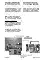
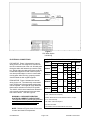
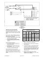
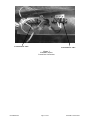
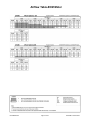
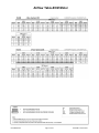
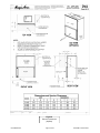
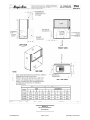
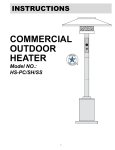
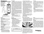
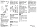
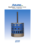
DV SERIES
Magic Aire Fan Coil Unit – Sizes 04 through 10
Installation, Operation and Maintenance Manual
The Magic Aire® Fan Coil Unit is
designed for use in any air distribution system. It is easily adaptable to
most types of existing or new forcedair heating systems, or it can be installed in an independent air cooling
system.
Pay particular attention to
the following words:
NOTE–intended to clarify or
make installation easier.
CAUTION–given to prevent
equipment damage.
WARNING–to alert installer
that personal injury and/or
equipment damage may result if installation procedure
is not properly followed.
GENERAL
Immediately inspect each unit
for damage upon receipt. File any
damage claims with the freight carrier. Protect stored units from damage. Do not stack more than two
high.
Use these instructions in conjunction
with other appropriate instructions,
including but not limited to those instructions supplied with the outdoor
unit (if applicable). Installation must
comply with all applicable local
codes.
EXISTING DUCT WORK
The previously installed air distribution system
for heating requires close inspection to determine
its suitability for cooling. In general, heating systems designed for outside temperatures of zero
degrees or lower will need no alteration when used
for cooling. However, in southern sections of the
country, the existing heating duct work may have
to be modified to provide better air distribution and
insulation for cooling.
DUCT INSULATION AND VAPOR PROOFING
Properly installed heating supply ducts should
already have adequate insulation against excessive heat loss. This same insulation should therefore be satisfactory in the summer to protect
against heat gain. However, depending on the
specific installation, it may be desirable to add to
the insulation.
All externally insulated duct work must have an
adequate vapor seal for summer operation. This is
particularly important where the duct is exposed to
highly humid conditions in such places as attic,
vented crawl spaces, unconditioned basements,
and utility rooms. The vapor seal prevents condensation of moisture in the insulating material and
subsequent loss of its insulating value.
NOTE: Consult a qualified insulation contractor
to insure your system is properly insulated.
035-000040-001
Page 1 of 18
DVA IOM 1.3 08-18-2014
THIS PAGE INTENTIONALLY LEFT BLANK
035-000040-001
Page 2 of 18
DVA IOM 1.3 08-18-2014
DV Series Air Handling Unit
Installation, Operation and Maintenance
Manual
Installation, Start-Up
and Service
Instructions
035-000040-001
Topic
Page
SAFETY CONSIDERATIONS
UNPACKING
INSTALLATION
Pre-installation
Floor Mounting
Ductwork
Condensate Drain
Refrigerant/Chilled Water Piping
Freeze Protection
Auxiliary Drain Pan
Refrigerant Connections, TXV or Orifice
Electrical
AIRFLOW DATA
SERVICE CLEARANCES
STARTUP REPORT
1, 5
1
5
5
5
6
6
6
6
6
7
8-11
12-13
14-15
17
Page 3 of 18
DVA IOM 1.3 08-18-2014
THIS PAGE INTENTIONALLY LEFT BLANK
035-000040-001
Page 4 of 18
DVA IOM 1.3 08-18-2014
INSTALLATION
1. Remove all packing and foreign material
from unit.
2. Check blower wheel for free rotation.
3. Check copper lines, coil etc for internal or
hidden damage. Maintain caps and plugs
until ready for connection to system.
4. In an attic installation where unit is resting
on the attic floor, a suitable isolation pad or
other vibration isolation should be provided
to minimize equipment sound transmission
to the living area.
5. The fan coil requires service clearances as
shown in Figures 8 and 9. Units are approved for 0” (zero inches) of clearance.
Units are designed for vertical (upflow or
downflow) airflow discharge only.
6. Mount unit on accessory legs (leg kit accessory) or field-provided stand. WARNING! Make sure to allow at least 4.5”
below the unit for the condensate drain
trap!
7. Mount Install condensate drain. See section “CONDENSATE DRAIN”.
8. Attach discharge and return ductwork. See
section “Placing Unit in Ductwork.”
9. Connect refrigerant liquid and suction piping to unit (DX coil). NOTE: Size and install per condensing unit manufacturer’s
recommendations.
10. Connect chilled water supply and return
piping to unit (Chilled Water coil).
CAUTION: Protect cabinet and internal
piping by wrapping each pipe with a wet
cloth while brazing.
The unit should be supported by a suitable
floor surface. Unit is not intended to be
suspended from a ceiling or roof deck.
WARNING: Insure that supporting
structure is adequate for the loads
being applied. Consult structural design professional if required.
Before installing any unit, the installer must
determine that the weight of the unit can be
safely supported by the floor joists, rafters,
ceiling, etc. Care should be taken to insure
that floor stand or other mounting surface is
located so as to not block the access doors,
interfere with the electrical, mechanical, or
drain functions of the units.
WARNING: Disconnect and Lock Out all
incoming power sources before connecting
to electrical service.
Attach L1 and L2 to motor neutral and
speed wire lead leads as shown on wiring
diagram on unit front panel. Refer to
nameplate for FLA, MCA and MOPD.
Units with field installed electric heater accessory may be equipped with fan relay.
035-000040-001
Page 5 of 18
DVA IOM 1.3 08-18-2014
SUPPLY AND RETURN DUCTWORK
1. Use flexible duct connectors to supply and
return connections to minimize sound transmission from unit to ductwork.
2. When the connecting return air duct is smaller than the coil inlet opening, construct the
transition piece so that the vertical and horizontal dimensions of the transition piece do
not increase more then one inch for every
seven inches of length of the transition piece.
3. For best performance, provide at least three
feet of straight duct work preceding the coil
inlet.
4. Install unit so that the entering chilled water is
on the leaving air side of the coil (Chilled Water coil). Refrigerant coils are supplied in the
proper orientation. NOTE: If reversed, capacity will be reduced.
5. Install unit so that it pitches slightly –(1/8
inch) – toward the condensate drain opening
that is to be used.
CONDENSATE DRAIN
Provide condensate drain piping material and
size per local code requirements. Provide P-trap
with minimum seal of 4.0 inches. Insure that Ptrap is installed below the drain elevation to allow
pan to drain fully. Pitch drain piping downward
with minimum slope of 1/8” per foot, or minimum
required by code. NOTE: Failure to provide
proper condensate drain trap may lead to
condensate overflow and property damage
and to unacceptable IAQ conditions. Auxiliary drain pan is recommended to prevent property damage in the event of blocked drainage
system piping.
install a watertight pan of corrosion-resistant metal
beneath the unit to catch over-flow which may
result from clogged drains or from other reasons.
Provide proper drain piping for this auxiliary pan.
Consult local codes for additional precautions before installation.
INSTALLATION OF CHILLED WATER LINES
(with Chilled Water Coils)
1. If the Fan Coil Unit is located where the
coil is subject to freezing during winter months,
protect the coil from freezing. The coil can be
protected by:
A. Use of glycol cooling fluid, and/or
B. Circulation of warm air over the coil.
CAUTION: Draining the system may
not protect the coil from freezing. How
ever, the system must be drained when
glycol has not been added, for minimal
protection.
2. Whenever glycol is added for the heating
season, the system may have to be flushed
prior to the start of the next cooling season
because of capacity loss due to glycol.
3. Insulate chilled water piping with good quality insulation material with vapor barrier that is
continuous up to the unit casing.
WARNING-AUXILIARY DRAIN PAN
RECOMMMENDED: Many municipalities have
adopted building codes that require the use of
auxiliary drain pans. Magic Aire holds that this
practice represents the standard for professional
installation whether or not such codes exist in a
specific municipality or territory. As such, water
damages that would have been prevented had
an auxiliary pan been deployed will not be considered for compensation. This position is taken
regardless of whether the source of the moisture
was specified as a potential failure mode in the
applicable building code or not. A freeze burst,
cracked drain pan, failed weld, or corrosion induced leak are some of the potential failure
modes that are mitigated when an auxiliary pan
is properly installed. Professional installers recognize the value of protecting customer assets
against foreseeable events. Customers who
choose to avoid the cost of common protective
measures waive their right to seek damages
when those foreseeable events occur. If the Fan
-Coil is located above a living space or where
damage may result from condensate overflow,
035-000040-001
Page 6 of 18
WARNING
FREEZE PROTECTION
Insure that the unit is protected against
freezing conditions.
Failure to provide
freeze protection may result in equipment or
property damage.
Freeze
protection
measures are customer-provided and installed and include but are not limited to low
-limit thermostats, automatic temperature
controls, and use of glycol based heat
transfer fluids.
See also section
“CONDENSATE DRAIN”.
Refrigerant coils may form ice (“freezing”)
under certain non-standard operating conditions. Magic Aire recommends use of a
field-provided and installed low limit thermostat on DX coils to prevent damage and
adverse operation caused by coil icing.
DVA IOM 1.3 08-18-2014
INSTALLATION OF REFRIGERANT LINES
Size and install refrigerant lines in accordance
with the condensing unit manufacturer’s instructions.
REFRIGERANT PIPING AT THE UNIT: Install
TXV sensing bulb 7 diameters downstream from
the manifold on a horizontal section of the suction
line in the 3-o'clock or 9-clock position. Insulate
the sensing bulb thoroughly so that it receives a
good temperature signal from the gas in the suction line. For 7/8" O.D. and larger suction lines,
use 4-o'clock or 8-o'clock position. Alternately,
the sensing bulb may be located on a descending
vertical section of the suction line.
FIELD INSTALLED TXV—Field Provided
Install field-provided TXV outside the unit cabinet in the liquid line. NOTE: Remove piston (if
present) from distributor. Make sure Teflon
gasket (ref Fig. 2) is present and in good condition, at the distributor. Connect equalizer line to
schrader valve connection at the coil. Use a
schrader depresser fitting or remove the schrader valve body so that the equalizer line reads the
suction line pressure. It is also acceptable to
braze-in a separate equalizer connection next to
the factory connection.
NOTE: Units with coil “less TXV” are shipped
with 3/8” Chatleff male refrigerant distributor and
with nut and liquid line stubout (3/8” copper tube).
NOTE: On a “less TXV” coil THERE IS NO PISTON METERING DEVICE PRESENT except with
the R-22 “orifice” option. The customer may size,
select and field install a piston to provide metering
without a TXV. For best results, use of the factory TXV is recommended. Field installable TXV is
available as an accessory.
FIELD INSTALLED TXV—Factory Provided
(Figure 2) Install Factory TXV by threading on to
the distributor. Remove piston (if present) from
distributor. Make sure Teflon gasket (ref Fig.
1) is present and in good condition, at the distributor and on the TXV. Connect equalizer line to
schrader valve connection at the coil.
Figure 1
Orifice Metering Option
Figure 2
TXV Installation
035-000040-001
Page 7 of 18
DVA IOM 1.3 08-18-2014
Figure 3
PSC Motor Option
Unit Wiring
ELECTRICAL CONNECTIONS
PSC MOTOR: Figure 3 illustrates the internal
wiring for the unit. The utility box is mounted on
the coil connection side of the unit. All leads pass
through a strain relief where they enter the utility
box. Wiring within the cabinet has been positively
located and supported so that it does not pass
over sharp metal edges or come in contact with
moving parts. After servicing, properly position
electrical leads in their original supports.
ECM MOTOR: Figure 6 indicates the internal
wiring for the unit. The electrically commutated
motor (ECM) has 5 discrete speed settings that
can be adjusted. The single fan relay allows the
thermostat to activate one of the 5 fan speeds.
The 24VAC, 40VA control transformer allows the
unit to power a thermostat and up to two water
flow control valves. See also Figure 8.
ELECTRICAL DATA - DVA with PSC MOTOR
Motor
Model
MCA MOPD
Voltage Phase HP FLA
115
DVA04
208-230
1
277
1/10
2.1
2.6
1/10
0.8
1.0
1/6
0.9
1.1
2.7
3.4
115
DVA06
DVA08
DVA10
208-230
1.0
1.3
277
0.9
1.1
115
4.1
5.1
1.3
1.6
277
2.0
2.5
115
6.9
8.6
2.2
2.8
2.4
3.0
208-230
208-230
1
1
1
277
1/6
1/4
1/3
15
15
15
15
Notes:
1.MCA = Minimum Circuit Ampacity
WARNING: CHECK MOTOR RATING
PLATE FOR CORRECT LINE VOLTAGE.
This appliance must be permanently grounded
in accordance with the National Electrical
Code and local codes and ordinances.
2.MOPD = Maximum Overcurrent Protective Device, in amps.
3.FLA = Full Load Amps
4.HP = Motor nominal horsepow er.
5.All motors are 60Hz.
6.Use minimum w ire size #14 AWG 75C w ire at unit.
NOTE: Reference Figures 4 and 5 for access
to motor and electrical components.
035-000040-001
Page 8 of 18
DVA IOM 1.3 08-18-2014
J Box
(Replaced by control
Box with ECM option)
Figure 4
Access Panels Removed
(PSC Motor option shown)
Figure 5
ECM Motor-Connection Detail
035-000040-001
Page 9 of 18
DVA IOM 1.3 08-18-2014
Figure 6
ECM Motor Option
Unit Wiring
ECM APPLICATION GUIDELINES
DV units with ECM motor have 5 preprogrammed speeds to choose from. Which
speed is active is selected using the terminal
block.
ECM ELECTRICAL DATA
How it works: Airflow, RPM and static pressure is similar to a PSC motor but more stable and much more efficient.
1. As system static pressure goes up, RPM
goes up and CFM goes down.
2. At around 1050rpm, as SP increases,
CFM decreases rapidly down to zero at
1200rpm.
Coil
Motor
hp
115V
208-230V
DVA04
All
1/3
3.2
2.2
DVA06
All
1/3
4.3
3
DVA08
All
1/3
4.3
3
DVA10
All
1/2
6.8
4.1
Notes:
1. Motor is Genteq X-13 or equivalent.
How to select the fan speed:
1. Use the airflow tables to locate the desired operating point.
2. Identify the corresponding tap number
from the table.
3. Move Violet wire (504) to the matching
connection on terminal block TB2.
2. Overload Protection: ECM motor is electronically protected.
How to integrate with 24V thermostat:
Connect R, C and G connections on terminal
block TB1 to matching connections on thermostat. Energizing the G connection will start
the fan.
035-000040-001
Motor FLA
Unit Size
3. Locked Rotor Amps: If motor speed decreases below a programmed stall speed, the motor will shut down and after a delay period, the
control will attempt to restart the motor. Starting current is limited to significantly less than
full load current.
4. Agency Listings for the motor: UL File:
E100625 Vol. 9 for Motor, Vol. 7 Sect. 14 for
Control; CSA File: LR80176
Page 10 of 18
DVA IOM 1.3 08-18-2014
Terminal Block “TB2”
Terminal Block “TB1”
Figure 7
ECM Motor OptionControl Box Connections
035-000040-001
Page 11 of 18
DVA IOM 1.3 08-18-2014
Airflow Table-ECM Motor
035-000040-001
Page 12 of 18
DVA IOM 1.3 08-18-2014
Airflow Table-ECM Motor
035-000040-001
Page 13 of 18
DVA IOM 1.3 08-18-2014
Figure 8
Service Clearances
(Upflow)
035-000040-001
Page 14 of 18
DVA IOM 1.3 08-18-2014
Figure 9
Service Clearances
(Downflow)
035-000040-001
Page 15 of 18
DVA IOM 1.3 08-18-2014
THIS PAGE INTENTIONALLY LEFT BLANK
035-000040-001
Page 16 of 18
DVA IOM 1.3 08-18-2014
AIR HANDLERS AND FAN
COILS
t ĂƌƌĂŶƚLJZĞŐŝƐƚƌĂƟŽŶĂŶĚ^ƚĂƌƚ-up Report
Warranty Registration Form: Complete
and submit this form within ten (10) days of
start-up to comply with the terms of the
Magic Aire warranty. Form must be completed to clearly indicate startup for each
unit being registered.
Mail Form(s) to Magic Aire
Warranty Department
501 Galveston St.
Wichita Falls, TX, 76301 or
Email [email protected]
Job Name
City
Sales Order #
Unit Tag
Model Number
Serial Number
Installer
Quantity of Units
STARTUP REPORT
Group
Checklist Item
Yes
No
Does electrical service correspond to unit nameplate?
Electrical/Operational
-Nameplate Supply Voltage/Phase
-Nameplate Rated FLA motor current (Amps).
Voltage:
Phase:
Actual Motor Current:
Does all field wiring conform to unit wiring diagram?
Is field-provided freeze protection present? (for DX and hydronic coils)
Is fan wheel turning the correct direction?
Structural
DX Systems
Are mixing box dampers operating properly?
Is the filter clean?
Is unit properly supported?
Is unit installed level (necessary for proper condensate drainage)?
Is properly sized condensate trap present?
Is the condensate disposal system operating correctly?
Is auxiliary external condensate drain pan installed as recommended
by the installation manual? (not required for valid warranty)
Is expansion valve bulb properly installed and insulated?
Is equalizer line connected to the suction line Schrader valve (or to
suction line if field-provided TXV)?
Has the DX system been charged with refrigerant according to the
condensing unit manufacturer’s instructions?
Piping Check
Is unit piping correct and insulated to prevent condensation?
Are the control valve packages piped correctly?
Are Valve packages properly insulated?
Are there any leaks detected?
-in the interior of the unit?
-at unit piping connections?
-at valve packages or other piping modified in the installation?
035-000040-001
Page 17 of 18
DVA IOM 1.3 08-18-2014
DV Series Air Handling Unit
Installation, Operation and Maintenance Manual
035-000040-001
Page 18 of 18
DVA IOM 1.3 08-18-2014