1
A8GT-TK type
Numeric Keypad Panel
User’s Manual
(Hardware)
Thank you for choosing the MELSEC-GOT Series.
To ensure correct use of this equipment, please read this manual
carefully before operating it.
MODEL
A8GT-TK-U
MODEL
1DM093
CODE
IB(NA)-68934-C(0406)MEE
MITSUBISHI Graphics Operation Terminal
z SAFETY PRECAUTIONS z
(Always read before starting use)
When using Mitsubishi equipment, thoroughly read this manual and the
associated manuals introduced in the manual. Also pay careful attention to
safety and handle the module properly.
These precautions apply only to the installation of Mitsubishi equipment and the
wiring with the external device. Refer to the user’s manual of the CPU module
to be used for a description of the PLC system safety precautions.
classify the safety precautions into two
These SAFETY PRECAUTIONS
categories: "DANGER" and "CAUTION".
DANGER
Procedures which may lead to a dangerous condition and
cause death or serious injury if not carried out properly.
CAUTION
Procedures which may lead to a dangerous condition and
cause superficial to medium injury, or physical damage
only, if not carried out properly.
CAUTION may also
Depending on circumstances, procedures indicated by
be linked to serious results.
In any case, it is important to follow the directions for usage.
Store this manual in a safe place so that you can take it out and read it
whenever necessary. Always forward it to the end user.
A-1
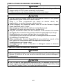
[PRECAUTIONS REGARDING ASSEMBLY]
DANGER
z When connecting the connection cable to the Numeric Keypad Panel,
always switch off GOT power externally in all phases.
A failure to do so can cause misoperation due to miss-input.
CAUTION
z Use the Numeric Keypad Panel in the environment defined in the general
specifications given in the GOT user's manual.
Using it in other environment can cause an electric shock, fire,
misoperation, or product damage or deterioration.
z When plugging the connection cable, insert it into the Numeric Keypad
Panel connector until it "clicks".
After plugging, check that the cable is inserted far enough.
Otherwise, mis-input can occur due to a contact fault.
z Plug the connection cable into the connector of the external I/O module
and tighten the connector fixing screws within the specified torque range.
Undertightening can cause mis-input due to a contact fault.
Overtightening can cause mis-input due to damaged screws or external
I/O module or a contact fault.
z When installing the Numeric Keypad Panel to a control box, mount or the
like, tighten the fixing screws within the specified torque range.
Undertightening can cause a drop.
Overtightening can cause a drop due to damaged screws or Numeric
Keypad Panel.
[PRECAUTIONS REGARDING WIRING]
DANGER
z Before starting wiring work, always switch power off externally in all
phases. A failure to do so can cause an electric shock, product damage or
misoperation.
CAUTION
z The FG wire of the connection cable and the FG terminal of the GOT's
power supply terminal block must be connected to ground separately using
a Class D or higher (Class 3 or higher) grounding method.
A-2
[PRECAUTIONS REGARDING AND MAINTENANCE]
CAUTION
z Do not disassemble or modify the Numeric Keypad Panel.
This can cause a failure, misoperation, injury or fire.
z The Numeric Keypad Panel case is made of resin.Do not drop it or give it
hard impact. This can cause the product to be damaged or fail.
z Always secure the connection cable connected to the Numeric Keypad
Panel and the power wires drawn from the connection cable, e.g. run them
in conduits or clamp them.
Otherwise, the Numeric Keypad Panel or cable can be damaged due to
dangling, moved or accidentally pulled cable or misoperation can occur
due to improper cable connection.
z Do not hold and pull the cable part when unplugging the connection cable
connected to the Numeric Keypad Panel or the power wires drawn from the
connection cable.
When the cable is fitted with a connector, hold the connector of the cable
part connected to the Numeric Keypad Panel.
If you pull the cable connected to the Numeric Keypad Panel, the Numeric
Keypad Panel or cable can be damaged or misoperation can occur due to
a contact fault.
[PRECAUTIONS REGARDING PRODUCT DISPOSAL]
CAUTION
z When disposing of this product, handle it as industrial waste.
A-3
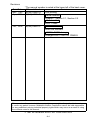
Revisions
* The manual number is noted at the lower left of the back cover.
Print Date
*Manual Number
Revision
Nov., 1997 IB(NA)-68934-A
First printing
Apr., 2001 IB(NA)-68934-B
Partial addition
Chapter 1, Section 2.1, Section 2.2
Models added
A9GT-70KBF
Jun., 2004 IB(NA)-68934-C
Partial correction
About the Manuals
MODEL CODE change
Changed from 13JM76 to 1DM093
This manual confers no industrial property rights or any rights of any other kind, nor does
it confer any patent licenses. Mitsubishi electric Corporation cannot be held responsible
for any problems involving industrial property rights which may occur as a result of using
the contents noted in this manual.
1997 MITSUBISHI ELECTRIC CORPORATION
A-4
CONTENTS
1. Introduction.................................................................................................... 1
2. System Configurations................................................................................... 2
3. Connection Cables ........................................................................................ 4
3.1 Cable for Connection between External I/O Module
and Numeric Keypad Panel ..................................................................... 4
3.1.1 Wiring method ................................................................................... 4
3.1.2 How to fabricate the cable ................................................................. 5
3.2 Cable for Connection between Terminal Block Conversion Module
and Numeric Keypad Panel ..................................................................... 7
4. Structure...................................................................................................... 10
5. Installation ................................................................................................... 11
6. Outline Drawing ........................................................................................... 12
A-5
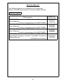
About the Manuals
The following product are available for this equipment.
Refer to the table given below to choose suitable manuals.
Relevant Manual
Manual name
A9GT-70KBF type external I/O interface module
User’s Manual
(Found in the packing of the A9GT-70KBF)
A8GT-70KBF type external I/O interface module
User’s Manual
(Found in the packing of the A8GT-70KBF)
A8GT-50KBF type external I/O interface module
User’s Manual
(Found in the packing of the A8GT-50KBF)
GOT-A900 Series User’s Manual (GT Works
Version5/GT Designer Version5 compatible Connection
System Manual)
(Available as an Option)
A-6
Manual No.
(Model code)
IB-80018
(1DM115)
IB-66769
(1DM064)
IB-68908
(1DM053)
SH-080119
(1DM189)
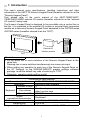
1. Introduction
This user's manual gives specifications, handling instructions and other
information of the A8GT-TK Numeric Keypad Panel (hereafter referred to as the
"Numeric Keypad Panel").
First, please refer to the user's manual of the A9GT-70KBF/A8GT70KBF/A8GT-50KBF external I/O module (hereafter referred to as the "external
I/O module") being used.
The Numeric Keypad Panel is designed to be mountable onto a control box or
the like. It is connected to the external I/O module or terminal block conversion
module as a data entry Numeric Keypad Panel dedicated to the GOT900 series
/GOT800 series (hereafter referred to as the "GOT").
External I/O
interface module
A8GT-TK
GOT
Restrictions on use
y Do not press two or more switches of the Numeric Keypad Panel at the
same time.
Pressing two or more switches simultaneously can cause mis-input.
y When setting any operation to each key of the Numeric Keypad Panel on
the GT Designer or the SW3NIW-A8GOTP graphic settings software
package, re-set the default key code of each key to “FFFF”.
Otherwise, operation setting will be invalid.
Performance Specifications
Connection interface
A9GT-70KBF/A8GT-70KBF/A8GT-50KBF
Application
Data entry from keyboard
Number of keys 31
Function keys, cursor keys, ten-key pad,
Keyboard
Key makeup
other function keys
Operational life 200,000 times
Online
Disallowed
connection/disconnection
Outline dimensions(mm/inch) 197/7.76(H)×70/2.76(W)×15/0.59(D)
Weight(kg/lb)
0.13/0.29
For general specifications, refer to the user's manual of the GOT used.
1
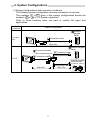
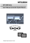
2. System Configurations
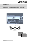
(1) System configurations and connection conditions
The following system configuration assumes connection of a printer.
The numbers (
to
) given in the system configurations denote the
numbers ( to ) in "(2) System equipment".
Refer to these numbers when you want to confirm the types and
applications.
Connection
conditions
System configuration
Numeric
Keypad
Panel
For input
only
Connection cable
Max.20m
Connector terminal
block conversion unit
Numeric Keypad
Panel
Connection cable
Connection cable
For I/O
General-purpose
output devices
(e.g.lamps, relays)
Connection cable
Max.10m
Max.10m
2
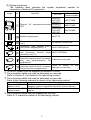
(2) System equipment
The following table indicates the system equipment needed for
connection of external I/O equipment.
Image
No.
Applicatin
External
GOT
I/O
GOT unit
equipment-connected
A985GOT,
A97*GOT,
A960GOT
A870GOT,
A810GOT
A956WGOT,
A95*GOT,
A85*GOT
Type
External I/O
interface module
A9GT-70KBF
A8GT-70KBF
A8GT-50KBF
Numeric keypad panel
A8GT-TK
Connector terminal block conversion
unit*1
A6TBY36-E, A6TBY54-E
Connection cable between [GOT]
and [numeric keypad panel]*1*2
A8GT-C05TK(0.5m)
Connection cable between [GOT]
and [connector terminal block
conversion unit]*1*3
Connection
cable
between
[connector terminal block conversion
unit] and [general-purpose I/O
equipment]*4
Connection
cable
between
[connector terminal block conversion
unit] and [numeric keypad panel]
A8GT-C30TB(3m)
Fabricate on user side
(Refer to Section 3.2
fabricate on user side.)
and
*1 12/24VDC power must be supplied for external I/O units.
*2 The connection cable may also be fabricated on user side.
Refer to Section 3.1 for details of the fabricating method.
*3 The connection cable may also be fabricated on user side.
Refer to the following manuals for details of the fabricating method.
GOT used
When the GOT-A900
Series is used
When the GOT800
Series is used
Manual Name
GOT-A900 Series User’s Manual (GT Works Version5/GT
Designer Version5 compatible Connection System Manual)
A8GT-50KBF type External I/O interface module User’s
Manual
*4 The connection cable must be prepared by the user.
Refer to *3 manual for details of the fabricating method.
3
3. Connection Cables
This chapter provides how to wire and fabricate the connection cables.
3.1 Cable for Connection between External I/O Module and Numeric
Keypad Panel
Use the following cable for connection between the external I/O module and
Numeric Keypad Panel.
y Type A8GT-C05TK Numeric Keypad Panel connection cable
(cable length:50cm (19.65 inch))
y User-fabricated connection cable (max. cable length:20m (65.62feet.))
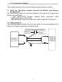
3.1.1 Wiring method
The following diagram shows how to wire the cable for connection between the
external I/O module and Numeric Keypad Panel.
External supply power(12/24VDC)
White wire
(connect to -)
Red wire
(connect to +)
Numeric
Keypad
Panel
External
I/O module
Green wire(ground wire)
4
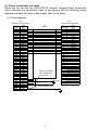
3.1.2 How to fabricate the cable
When you do not use the A8GT-C05TK Numeric Keypad Panel connection
cable, fabricate the connection cable in accordance with the following wiring
diagram and parts list (max. cable length: 20m (65.62 feet)).
(1) Wiring diagram
1) 2)
External I/O module side
Pin
number
Signal
name
B4
A4
B3
A3
B2
A2
B1
A1
B8
A8
B7
A7
B6
A6
B5
A5
A9
B9
A10
B10
A11
B11
A12
B12
A13
B13
A14
B14
A15
B15
A16
B16
A17
B17
A18
B18
A19
B19
A20
B20
XD0
XD1
XD2
XD3
XD4
XD5
XD6
XD7
XSCN0
XSCN1
XSCN2
XSCN3
XSCN4
XSCN5
XSCN6
XSCN7
YD15
YD14
YD13
YD12
YD11
YD10
YD9
YD8
YD7
YD6
YD5
YD4
YD3
YD2
YD1
YD0
12/24VDC
12/24VDC
12/24VDC
0V
0V
Empty
Empty
FG
3) 4)
Numeric Keypad Panel
5)
Shield
Wires for connection
with external input
power supply 7)
12/24VDC
Connect shield to FG.
6)
5
Pin
number
Signal
name
1
19
2
20
3
21
4
22
6
24
7
25
8
26
9
27
5
23
10
28
11
29
12
30
13
31
14
32
15
33
16
34
17
35
18
36
XD0
XD1
XD2
XD3
XD4
XD5
XD6
XD7
XSCN0
XSCN1
XSCN2
XSCN3
XSCN4
XSCN5
XSCN6
XSCN7
Must not be used.
Must not be used.
Must not be used.
Must not be used.
Must not be used.
Must not be used.
Must not be used.
Must not be used.
Must not be used.
Must not be used.
Must not be used.
(2) Parts list
Number
Name
1)
Connector
2)
3)
4)
Number
5)
6)
7)
Connector
cover
Connector
Connector
cover
Type
Maker
Qty
FCN-361J040-AU
1
FCN-360C040-B
FUJITSU LTD.
1
Tightening torque range:
35 to 48N·cm
Japan Aviation
D05-36PC-F0
Electronics
1
D05-36H-S
Industry, Ltd.
Name
Type
Twisted
pair Conductor OD:1.0mm (0.04 inch)
shielded cable (equivalent to UL 2935 AWG28)
Conductor OD:1.8mm (0.07 inch)
FG wire
(equivalent to UL 1015 AWG14)
External input
power supply Conductor OD:0.6mm (0.02 inch)
(equivalent to UL 1007 AWG24)
connecting
wire
6
Qty
1
1
2
F1
F2
F3
F4
F5
F6
F7
F8
XD0
7
12/24VDC
1D -C -C 1E
Load
1C
Load
1B
Load
19 -C -C 1A
Load
18
Load
17
Load
15 -C -C 16
Load
14
Load
13
Load
11 -C -C 12
Load
Load
10
Load
Load
Load
Load
Load
Loads:Lamps,relays,etc.
(A6TBY36-E)
Terminal block conversion module
9 -C -C A
8
0
F9
XD1
F10
XD2
1 -C -C 2
XD3
3
SP
XD4
4
XD5
XD6
5 -C -C 6
1
7
2
8
3
9
.
4
0
5
SCR UP
Numeric Keypad Panel
SCR DWN
6
BS
XD7
7
XSCN
0
XSCN1
XSCN2
XSCN3
XSCN4
XSCN5
XSCN6
XSCN7
B
1F -C
C D -C -C E
24V
F -C
0V
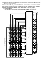
3.2 Cable for Connection between Terminal Block Conversion Module and
Numeric Keypad Panel
Fabricate the cable for connection between terminal block conversion module
and Numeric Keypad Panel in accordance with the following wiring diagram,
parts list and assembly diagram (max. cable length: 10m (32.79feet)).
(1) Wiring diagram
(a) For use of the terminal block conversion module (A6TBY36-E)
F1
F2
F3
F4
F5
F6
F7
F8
XD0
8
XD7
7
Load
Load
Load
Load
Load
Load
Load
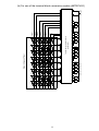
Loads:Lamps,relays,etc.
1D -C -C 1E
1C
1B
B
19 -C -C 1A
9 -C -C A
8
18
(A6TBY54-E)
Terminal block conversion module
XD5
XD6
5 -C -C 6
XSCN
0
XSCN1
XSCN2
17
4
1
2
3
XSCN3
XSCN4
XSCN5
XSCN6
Load
15 -C -C 16
XD4
7
8
9
.
-
0
BS
Load
14
XD3
3
SCR UP
4
5
6
XSCN7
Load
13
XD2
1 -C -C 2
SP
SCR DWN
Load
11 -C -C 12
XD1
F10
Load
10
0
F9
Numeric Keypad Panel
1F -C
0V
F -C
12/24VDC
24V
C D -C -C E
(b) For use of the terminal block conversion module (A6TBY54-E)
Load
Load
Load
Load
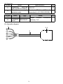
(2) Parts list
Number
Name
Specifications
Qty
Solderless
termi-nal
1.25-3.5
16
1)
(with insulat-ion sleeve)
Twisted
pair Conductor OD: 1mm (0.04 inch)
2)
1
shielded cable
(equivalent to UL 2935 AWG28)
Number
Name
Type
Maker
Qty
3)
Connector D05-36PC-F0
Japan Aviation Electronics
1
Connector
Industry, Ltd.
D05-36H-S
4)
cover
(3) Assembly diagram
1)
3) 4)
2)
9
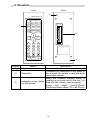
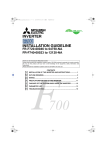
4. Structure
(Front)
(Rear)
3)
MELSEC/A8GT-TK
F1
F2
F3
F4
F5
F6
F7
F8
F9
F10
SCROLL
UP
SCROLL
DOWN
1)
2)
7
8
9
4
5
6
1
2
3
0
SP
BS
3)
Number
1)
Keys
2)
3)
Name
Description
Used to enter data.
Connector for connection of the cable to
Connector
the external I/O module or terminal block
conversion module.
When the Numeric Keypad Panel is
installed on a control box or the like, it is
Installation screw holes
fixed with M4 screws (user prepared).
(for M4 screws)
Screw hole depth: 5mm(0.20inch)
Tightening torque range: 62 to 83.5N·cm
10
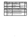
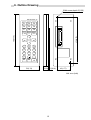
5. Installation
When installing the Numeric Keypad Panel on a control box door, mount or the
like, the door or mount must be machined.
The following diagram shows mounting panel machining dimensions.
Mounting panel machining dimensions (front view)
(13.75)
{0.54}
172{0.77}
Square
hole
79{3.11}
32.75{1.29}
2f5
45{1.77}
25.5
{1.0}
25{0.98}
(15.5)
{0.61}
11
Unit:mm{inch}
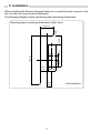
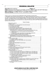
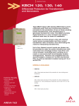
6. Outline Drawing
2-M4 screw,depth 5(0.20)
MELSEC/A8GT-TK
F2
F3
F4
F5
F6
F7
F8
F9
F10
SCROLL
UP
SCROLL
DOWN
7
8
9
4
5
6
1
2
3
172(6.77)
197(7.76)
F1
0
SP
BS
70(2.76)
15
(0.59) 4.5(0.18)
45(1.77)
Unit: mm (inch)
12
Warranty
Mitsubishi will not be held liable for damage caused by factors found not to be the cause of
Mitsubishi; machine damage or lost profits caused by faults in the Mitsubishi products;
damage, secondary damage, accident compensation caused by special factors
unpredictable by Mitsubishi; damages to products other than Mitsubishi products; and to
other duties.
For safe use
y This product has been manufactured as a general-purpose part for general industries,
and has not been designed or manufactured to be incorporated in a device or system
used in purposes related to human life.
y Before using the product for special purposes such as nuclear power, electric power,
aerospace, medicine or passenger movement vehicles, consult with Mitsubishi.
y This product has been manufactured under strict quality control. However, when installing
the product where major accidents or losses could occur if the product fails, install
appropriate backup or failsafe functions in the system.
Country/Region Sales office/Tel
U.S.A
Mitsubishi Electric Automation Inc.
500 Corporate Woods Parkway Vernon
Hills, IL 60061
Tel : +1-847-478-2100
Brazil
MELCO-TEC Rep. Com.e Assessoria
Tecnica Ltda.
AV. Paulista 1471, Conj. 308,
Sao Paulo City, Sao Paulo State,
Brazil
Tel : +55-11-283-2423
Germany
Mitsubishi Electric Europe B.V. German
Branch
Gothaer Strasse 8 D-40880 Ratingen,
GERMANY
Tel : +49-2102-486-0
U.K
Mitsubishi Electric Europe B.V. UK
Branch
Travellers Lane, Hatfield, Herts., AL10
8XB,UK
Tel : +44-1707-276100
Italy
Mitsubishi Electric Europe B.V. Italian
Branch
Centro Dir. Colleoni, Pal. Perseo-Ingr.2
Via Paracelso 12, 20041 Agrate B.,
Milano, Italy
Tel : +39-039-6053344
Spain
Mitsubishi Electric Europe B.V. Spanish
Branch
Carretera de Rubi 76-80
08190 - Sant Cugat del Valles,
Barcelona, Spain
Tel : +34-93-565-3131
France
Mitsubishi Electric Europe B.V. French
Branch
25 Boulevard des Bouvets, F-92741
Nanterre Cedex, France
TEL: +33-1-5568-5568
South Africa
Circuit Breaker Industries LTD.
Tripswitch Drive, Elandsfontein Gauteng,
South Africa
Tel : +27-11-928-2000
Country/Region Sales office/Tel
Hong Kong
Ryoden Automation Ltd.
10th Floor, Manulife Tower, 169 Electric
Road, North Point, HongKong
Tel : +852-2887-8870
China
Ryoden Automation Shanghai Ltd.
3F Block5 Building Automation
Instrumentation Plaza 103 Cao Bao Rd.
Shanghai 200233 China
Tel : +86-21-6475-3228
Taiwan
Setsuyo Enterprise Co., Ltd.
6F., No.105 Wu-Kung 3rd.RD, Wu-Ku
Hsiang, Taipei Hsine, Taiwan
Tel : +886-2-2299-2499
Korea
HAN NEUNG TECHNO CO.,LTD.
1F Dong Seo Game Channel Bldg.,
660-11, Deungchon-dong Kangsec-ku,
Seoul, Korea
Tel : +82-2-3660-9552
Singapore
Mitsubishi Electric Asia Pte, Ltd.
307 ALEXANDRA ROAD #05-01/02,
MITSUBISHI ELECTRIC BUILDING
SINGAPORE 159943
Tel : +65-6473-2308
Thailand
F. A. Tech Co.,Ltd.
898/28,29,30 S.V.City Building,Office
Tower 2,Floor 17-18 Rama 3 Road,
Bangkpongpang, Yannawa,
Bangkok 10120
Tel : +66-2-682-6522
Indonesia
P.T. Autoteknindo SUMBER MAKMUR
Jl. Muara Karang Selatan Block A Utara
No.1 Kav. No.11 Kawasan Industri/
Pergudangan Jakarta - Utara 14440
Tel : +62-21-663-0833
India
Messung Systems Put,Ltd.
Electronic Sadan NO:111 Unit No15,
M.I.D.C BHOSARI,PUNE-411026
Tel : +91-20-712-2807
Australia
Mitsubishi Electric Australia Pty. Ltd.
348 Victoria Road, PostalBag, No 2,
Rydalmere, N.S.W 2116, Australia
Tel : +61-2-9684-7777
HEAD OFFICE : 1-8-12, OFFICE TOWER Z 14F HARUMI CHUO-KU 104-6212, JAPAN
NAGOYA WORKS : 1-14, YADA-MINAMI 5-CHOME, HIGASHI-KU, NAGOYA, JAPAN
When exported from Japan, this manual does not require application to the Ministry
of Economy, Trade and Industry for service transaction permission.
Specifications subject to change without notice.
Printed in Japan on recycled paper.