1
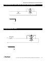
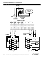
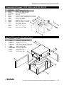
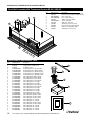
Delfield
™
®
SHELLEYBASIC BY DELFIELD
Service, Installation and Care Manual
Please read this manual completely before attempting to install or operate this equipment!
Notify carrier of damage! Inspect all components immediately. See page 2.
N
CAUTIO
ATION
M
R
O
F
ANT IN
T
R
O
P
SE
U
IM
E
R
O
F
E
NS!
O
I
T
C
READ B
U
STR
N
I
E
S
E
E TH
V
A
S
E
S
PLEA
Effective Date June 2008
Shelleybasic by Delfield Service & Installation Manual
Contents
Serial Number Information...................................................... 2
Receiving And Inspecting The Equipment.............................. 2
Specifications ..................................................................... 3-4
Installation.............................................................................. 5
Operation............................................................................. 6-7
Reversing And Replacing Panels........................................... 7
Maintenance........................................................................... 8
Wiring Diagrams................................................................ 9-12
Replacement Parts.......................................................... 13-16
Standard Labor Guidelines................................................... 17
Standard Warranties............................................................. 18
Serial Number Information
The serial number on self-contained refrigerated units is on the
electrical specifications tag located near the condensing unit.
On hot food pans and hot/cold combination pans, the serial
number tag is located on the bottom shelf of the cabinet.
The serial number tag also lists the refrigerant used and the
amount of charge.
Always have the serial number of your unit available when
calling for parts or service. A complete list of authorized Delfield
parts depots is available at www.delfield.com.
©2008 The Delfield Company. All rights reserved. Reproduction without written
permission is prohibited. Delfield is a registered trademark of The Delfield
Company.
Notes.................................................................................... 19
Receiving And Inspection The Equipment
Even though most equipment is shipped crated, care
should be taken during unloading so the equipment is
not damaged while being moved into the building.
1. Visually inspect the exterior of the package and skid
or container. Any damage should be noted and
reported to the delivering carrier immediately.
2. If damaged, open and inspect the contents with the
carrier.
3. In the event that the exterior is not damaged, yet
upon opening, there is concealed damage to the
equipment notify the carrier. Notification should be
made verbally as well as in written form.
4. Request an inspection by the shipping company of
the damaged equipment. This should be done within
10 days from receipt of the equipment.
5. Check the lower portion of the unit to be sure legs or
casters are not bent.
6. Also open the compressor compartment housing
and visually inspect the refrigeration package. Be
sure lines are secure and base is still intact.
7. Freight carriers can supply the necessary damage
forms upon request.
8. Retain all crating material until an inspection has
been made or waived.
Uncrating the Equipment
First cut and remove the banding from around the crate.
Remove the front of the crate material, use of some tools
will be required. If the unit is on legs remove the top of
the crate as well and lift the unit off the skid. If the unit
is on casters it can be "rolled" off the skid.
Delfield
™
For customer service, call (800) 733-8829, (800) 733-8821, Fax (989) 773-3210, www.delfield.com
®
Shelleybasic by Delfield Service & Installation Manual
Specifications
Shelleybasic by Delfield Heated Counters
Model
L
D
H
Ship Wt
Food
Wells
Volts
Plug
Amp
SE-H2
39”
29”
36”
215lbs (98kg)
2
120/208-230
14-20P
10.0/11.0
SE-H3
50”
29”
36”
265lbs (120kg)
3
120/208-230
14-20P
15.0/16.0
SE-H4
64”
29”
36”
320lbs (145kg)
4
120/208-230
14-30P
20.0/22.0
SE-H5
78”
29”
36”
410lbs (186kg)
5
120/208-230
14-50P
24.0/27.0
SE-H6
92”
29”
36”
500lbs (227kg)
6
120/208-230
14-50P
29.0/32.0
Shelleybasic by Delfield Refrigerated Cold Pan Serving Counters
Model
L
D
H
Ship Wt
12 X 20
Pans
Volts
Plug
Amp
H.P.
Ref Chrg.
BTU
Load
Sys.
Cap.
Evap BTU/
TD/Temp
SE-C2
39”
29”
36”
340lbs (154kg)
2
115
5-15P
4.0
1/5
8.0 oz
379
812
26/31°/4°
SE-C3
50”
29”
36”
415lbs (188kg)
3
115
5-15P
4.0
1/5
8.0 oz
569
889
35/26°/9°
SE-C4
64”
29”
36”
490lbs (222kg)
4
115
5-15P
7.0
1/4
12.0 oz
758
1373
43/32°/3°
SE-C5
78”
29”
36”
565lbs (256kg)
5
115
5-15P
7.0
1/4
12.0 oz
948
1469
51/29°/6°
SE-C6
92”
29”
36”
640lbs (290kg)
6
115
5-15P
7.0
1/3
16.0 oz
1138
1921
59/32°/3°
Shelleybasic by Delfield Hot / Cold Self-Contained Combination Counters
Model
L
D
H
Ship Wt
12 X 20
Pans
Volts
Plug
Amp
H.P.
Ref Chrg.
BTU
Load
Sys.
Cap.
Evap BTU/
TD/Temp
SE-HC2
39”
29”
36”
350lbs (159kg)
2
120
5-30P
24.0
1/4
8.0 oz
379
1112
26/42°/-7°
SE-HC3
50”
29”
36”
425lbs (193kg)
3
120/240
14-30P
21.0
1/4
8.0 oz
569
1259
35/36°/-1°
SE-HC4
64”
29”
36”
500lbs (227kg)
4
120/240
14-30P
21.0
1/4
12.0 oz
758
1373
43/32°/3°
SE-HC5
78”
29”
36”
575lbs (261kg)
5
120/240
14-60P
42.0
1/4
12.0 oz
948
1469
51/29°/6°
SE-HC6
92”
29”
36”
650lbs (295kg)
6
120/240
14-60P
42.0
1/3
16.0 oz
1138
1787
59/30°/5°
Shelleybasic by Delfield Ice Cooled Serving Counters
Model
L
D
H
Ship Wt
12 X 20 Pans
SE-I2
39”
29”
36”
200lbs (91kg)
2
SE-I3
50”
29”
36”
245lbs (111kg)
3
SE-I4
64”
29”
36”
280lbs (127kg)
4
SE-I5
78”
29”
36”
330lbs (150kg)
5
SE-I6
92”
29”
36”
380lbs (172kg)
6
Shelleybasic by Delfield Frost Top Counters
Model
L
D
H
Ship Wt
Volts
Plug
Amp
H.P.
Ref Chrg.
BTU
Load
Sys.
Cap.
Evap BTU/
TD/Temp
SE-F2
39”
29”
36”
370lbs (168kg)
115
5-15P
7.5
1/4
24.0 oz
379
1112
26/42°/-7°
SE-F3
50”
29”
36”
445lbs (202kg)
115
5-15P
7.5
1/4
24.0 oz
569
1259
35/36°/-1°
SE-F4
64”
29”
36”
530lbs (240kg)
115
5-15P
7.5
1/4
24.0 oz
758
1373
43/32°/3°
SE-F5
78”
29”
36”
600lbs (272kg)
115
5-15P
8.0
1/4
24.0 oz
948
1469
51/29°/6°
SE-F6
92”
29”
36”
670lbs (304kg)
115
5-15P
8.0
1/3
24.0 oz
1138
1787
59/30°/5°
SES model specifications are the same as SE model specifications, except SES model height is 30”.
Delfield
™
®
For customer service, call (800) 733-8829, (800) 733-8821, Fax (989) 773-3210, www.delfield.com
Shelleybasic by Delfield Service & Installation Manual
Specifications continued
Shelleybasic by Delfield Utility Counters
Model
L
D
H
Ship Wt
SE-U2
39”
29”
36”
150lbs (68kg)
SE-U3
50”
29”
36”
170lbs (77kg)
SE-U4
64”
29”
36”
200lbs (91kg)
SE-U5
78”
29”
36”
230lbs (104kg)
SE-U6
92”
29”
36”
280lbs (127kg)
Shelleybasic by Delfield Cashier’s Stand
Model
L
D
H
Ship Wt
SE-CS
29”
29”
36”
170lbs (77kg)
Shelleybasic by Delfield Tray Stand
Model
L
D
H
Ship Wt
SE-TS
39”
29”
36”
140lbs (64kg)
Shelleybasic by Delfield Ice Cream Counters - 0 degree only
Model
L
D
H
Ship Wt
Cabinet
Capacity
Volts
Plug
Amp
H.P.
Ref Chrg.
BTU
Load
Sys.
Cap.
Evap BTU/
TD/Temp
SE-ICE1
39”
29”
36”
460lbs (209kg)
84 cups
115
5-15P
5.3
1/4
7.0 oz
292
569
20/28°/-31°
SE-ICE2
50”
29”
36”
505lbs (229kg)
224 cups
115
5-15P
5.3
1/4
9.0 oz
473
661
28/24°/-24°
Shelleybasic by Delfield Corner Units
Model
L
D
H
Ship Wt
SE-29
29”
29”
36”
110lbs (50kg)
SE-39
39”
29”
36”
160lbs (73kg)
SES model specifications are the same as SE model specifications, except SES model height is 30”.
Delfield
™
For customer service, call (800) 733-8829, (800) 733-8821, Fax (989) 773-3210, www.delfield.com
®
Shelleybasic by Delfield Service & Installation Manual
Installation
Location
Units represented in this manual are for indoor use only. Be
sure the location chosen has a floor strong enough to support
the total weight of the cabinet and contents. A fully loaded
model may weigh as much as 3000 pounds! Reinforce the floor
as necessary to provide for maximum loading.
Electrical Connection
A standard unit is provided with a power cord and grounded
plug.
The unit should be plugged into a receptacle with its own circuit
protection that matches the amperage of the plug.
For the most efficient refrigeration, be sure to provide good air
circulation inside and out. Be sure that the exterior of the unit
has access to ample air. Avoid hot corners and locations near
stoves and ovens. It is suggested the rear of the unit be no
less than two inches from any wall, partition or any other object
which will restrict exhaust air flow.
Connections must be made in accordance
with all applicable local codes and/or the
National Electrical Code. Refer to the
amperage data on pages 3-4 and the wiring
diagrams on pages 9-12 to be sure the unit
is connected to the proper power source. A
protected circuit of the correct voltage and
amperage must be run for connection of the
line cord.
Unit requires that the sides and bottom are not
any closer than 3” to any combustible material.
DANGER
Leveling
A level cabinet looks better and will perform more efficiently
when the doors line up with the door frames properly, the
cabinet will not be subject to undue strain and the corners of the
shelves will not move around on the supports. A level heated
unit will maintain an equal water depth when water is used in
the wells. Use a level to make sure the unit is level from front to
back and side to side.
Stabilizing
On cord-connected units, the ON/OFF switch
must be turned to its OFF position and
power supply disconnected whenever doing
the following:
1. Performing maintenance functions.
2. Cleaning the refrigerated cabinet area.
3. Performing service or repair functions.
Under no circumstances should a refrigerated unit be operated
without the louvered panel in place.
All models are supplied on casters for your convenience, ease
of cleaning underneath and for mobility.
The unit must be installed in a stable
condition with the front wheels locked,
locking the front casters after installation is
the owner’s responsibility.
Plumbing
Refrigerated units have a drain that exits the unit on the bottom
and is located on the operator’s left side. Standard units on
casters or legs will have a bronze gate valve that fits a standard
garden hose. Drain connections are on the operator side below
the pan in the open shelf area.
CAUTION
Moisture collecting from improper drainage
can create a slippery surface on the floor
and a hazard to employees. It is the owner’s
responsibility to provide a container or
outlet for drainage.
Delfield
™
®
For customer service, call (800) 733-8829, (800) 733-8821, Fax (989) 773-3210, www.delfield.com
Shelleybasic by Delfield Service & Installation Manual
Operation SE-C And SES-C
There is a switch on the right side of the compressor stand used
to turn the unit on and off.
These units are designed to hold cold food product between
33°F to 41°F (0.6°C to 5°C).
Cold pans are adjusted at the factory to provide satisfactory
operation without any further adjustments. However, if it is
necessary to adjust the temperature, the control is located in the
machine compartment. Turn the knob clock-wise as indicated
on the control. Settings are from 1 through 7; 7 being the
coldest. Adjustments should be made gradually. Several small
adjustments will be more effective than one large adjustment. It
may take an hour or longer to realize the temperature change
depending on the application and location of the unit.
These units are not designed to cool warm food products.
Items should be placed in the unit pre-cooled at least to
the desired holding temperature, if not slightly colder. In
some applications, a gradual warming of product may occur,
particularly at the exposed top of the product. Stirring or
rotation of the product may be necessary to maintain overall
temperature. Warming of food product can occur very quickly
outside of the unit. When loading or rotating product, avoid
leaving food items in a non-refrigerated location to prevent
warming or spoilage.
When the cold pan is used with ice, use perforated bottoms.
These will allow ice to melt properly.
The unit must be turned off when not in use or overnight for
defrosting and cleaning.
Operation SE-H And SES-H
These units are designed to hold warm food product between
140˚F to 160˚F (60˚C to 71˚C).
Individually heated hot food units may be operated “wet”
(with water in the wells) or “dry”. However, “wet” operation is
recommended for better performance.
After plugging in the power supply cord, select desired
temperature by rotating temperature control. A knob and
indicator light are provided for each individual heated food well.
First Time Use
Before the unit is used the first time for serving, turn the
temperature knob to HI and heat the well for 20 to 30 minutes.
Any residue or dust that adhered to the heater element(s) will
be burned off during this initial preheat period.
When serving thick sauces always operate the hot food well in
“wet” operation. This provides more uniform temperature for
the sauce.
Never place food directly in well. Always use
pans.
For most efficient operation, keep covered insets in each well
during preheating or when empty.
Always place covers on pans when not serving to prevent food
from drying out.
Wet Operation
Fill the food well with about 2” of water and cover with lid or
empty pan. To preheat water, set temperature control at HI.
With pans in place, wells will boil water. Food temperature will
vary depending on type and amount of product. To minimize
steam and water usage, set control to lowest setting that will
maintain proper food temperature. To reduce preheating time,
use hot water to fill the well.
When operating these units “wet”, never use
anything other than plain water in the wells
or tank. Failure to observe this warning may
result in personal injury or damage to the
unit.
When operated at the highest temperature
setting, the top of the unit will become
very hot. Staff and customers using the
equipment should be informed about this.
Steam can cause serious burns. Always
wear some type of protective covering on
your hands and arms when removing lids
from the unit. Lift the lid in a way that will
direct escaping steam away from your face
and body.
Dry Operation
Wet operation is usually much more efficient and is preferred.
However, these units may be operated without water with no
damage to the unit.
When operated dry, the bottom of the well will discolor. To
clean, use a stainless steel cleaner or mild abrasive.
The dry well should never be preheated longer
than 15 minutes.
When operated dry, the well bottoms become
very hot. Do not allow unprotected skin to
contact any well surface.
Delfield
™
For customer service, call (800) 733-8829, (800) 733-8821, Fax (989) 773-3210, www.delfield.com
®
Shelleybasic by Delfield Service & Installation Manual
Operation SE-F And SES-F
Frost tops are designed to maintain an even layer of frost to
pleasantly display desserts and pies. Once turned on, the
compressor will run continuously. The unit should be turned off
overnight or when not in use.
Since it takes time for frost to accumulate initially, the unit
should be turned on approximately an hour before it is actually
required. Product should not be placed on the frost top prior to
turning the unit on, because it may freeze to the surface of the
unit.
Operation SE-HC And SES-HC
The hot and cold combination pans must be operated with
water in the well.
Hot Operation
Fill well with a minimum of 4” of water. Place function switch
in HOT position. Turn thermostat dial to highest position and
allow unit to warm up. Then reset the thermostat to maintain
the desired temperature.
Never use anything more than plain water in the
wells or tank. Failure to observe this warning
may result in personal injury or damage to the
unit.
When operated at the highest temperature
setting, the top of the unit will become very
hot. Staff and customers using the equipment
should be informed about this.
To turn unit off, simply move the function switch to OFF
position. Drain water and allow unit to cool before cleaning or
switching to cold operation.
Cold Operation
Simply place the function switch to the COLD position. The
compressor controller has been factory set and no temperature
adjustment should be necessary. When the cold pan is used
with ice, use perforated bottoms. These will allow ice to melt
properly.
Reversing And Replacing Panels
Shelleybasic laminated panels are reversible. All panels are
replaceable. The panels sit in an upper and lower track.
Switching from Hot to Cold Operation
Follow the following procedure:
1) Place the function switch in the OFF position
and drain off hot water.
2) Allow the unit to cool until it can be safely
cleaned.
3) When clean up procedures are complete,
unit will be ready for cold operation.
To assure maximum compressor life, do not
switch from “hot” to “cold” operation without
allowing a cool down period. Never switch from
hot to cold operation while hot water remains in
the pans. Failure to observe this warning will
greatly reduce compressor life and eventually
cause premature compressor failure.
Switching from Cold to Hot Operation
No special procedure is required to switch from cold to hot
operation. Be sure to fill with a minimum of 4” of water.
This unit is designed so that the compressor
and the heating elements cannot operate at
the same time. Continued operation of the
compressor in the “hot position” should not
be considered normal. Call for service if this
happens.
The unit must be turned off when not in use or overnight for
defrosting and cleaning.
To install new or reversed panels, insert the panel into the
upper track. Continue placing the panel into the unit and lower it
into the lower track.
Remove first an end panel. Gain access from the back of the
unit. Place one hand inside the unit on the panel, and one hand
on the panel outside the unit. Push the panel out and lift the
panel up. Remove the panel from the lower track and then the
upper track. By removing an end panel first you will have better
access to the front panel. Repeat the process for the front panel
and the other end panel.
Delfield
™
®
For customer service, call (800) 733-8829, (800) 733-8821, Fax (989) 773-3210, www.delfield.com
Shelleybasic by Delfield Service & Installation Manual
Maintenance
Drain Maintenance - Base
Each unit has a drain located inside the unit that removes
the condensation from the evaporator coil and routes it to an
external condensate evaporator pan. Each drain can become
loose or disconnected during normal use. If you notice water
accumulation on the inside of the unit be sure the drain tube
is connected to the evaporator drain pan. If water is collecting
underneath the unit make sure the end of the drain tube is in
the condensate evaporator in the machine compartment. The
leveling of the unit is important as the units are designed to
drain properly when level. Be sure all drain lines are free of
obstructions.
Caster Maintenance
Wipe casters with a damp cloth monthly to prevent corrosion.
The power switch must be turned to OFF and the
unit disconnected from the power source whenever
performing service, maintenance functions or
cleaning.
Stainless Steel Care and Cleaning
To prevent discoloration or rust on stainless steel several
important steps need to be taken. First, we need to understand
the properties of stainless steel. Stainless steel contains 70- 80%
iron, which will rust. It also contains 12-30% chromium, which
forms an invisible passive film over the steel’s surface, which
acts as a shield against corrosion. As long as the protective
layer is intact, the metal is still stainless. If the film is broken or
contaminated, outside elements can begin to breakdown the
steel and begin to form discoloration or rust. Proper cleaning of
stainless steel requires soft cloths or plastic scouring pads.
regularly. It is recommended that this be done at least every
three months. If conditions are such that the condenser is totally
blocked in three months, the frequency of cleaning should be
increased. Clean the condenser with a vacuum cleaner or stiff
brush. If extremely dirty, a commercially available condenser
cleaner may be required.
Failure to maintain a clean condenser coil can initially cause high
temperatures and excessive run times. Continuous operation
with a dirty or clogged condenser coil can result in compressor
failure. Neglecting the condenser coil cleaning procedures will
void any warranties associated with the compressor and cost to
replace the compressor.
Never use a high-pressure water wash for this
cleaning procedure as water can damage the
electrical components located near or at the
condenser coil.
Units with pans should be operated with pans in
place. Operating the unit without all pans in place
will lower efficiency and may damage the unit.
Defrosting
Refrigerated cold pans and frost tops should be defrosted
daily. Ice Cream counters require defrosting after 3/8 to 1/2 of
frost forming. Frost top ON/OFF switch is located in machine
compartment. Cold pan thermostat has an OFF position.
Never use sharp objects or tools to clean or scrape ice/
frost build up from the refrigerated cold pans or frost tops.
A puncture to the pan could cause irreparable damage to
the refrigeration system.
NEVER USE STEEL PADS, WIRE BRUSHES OR SCRAPERS!
Cleaning solutions need to be alkaline based or non-chloride
cleaners. Any cleaner containing chlorides will damage
the protective film of the stainless steel. Chlorides are also
commonly found in hard water, salts, and household and
industrial cleaners. If cleaners containing chlorides are used be
sure to rinse repeatedly and dry thoroughly. Routine cleaning
of stainless steel can be done with soap and water. Extreme
stains or grease should be cleaned with a non-abrasive cleaner
and plastic scrub pad. Always rub with the grain of the steel.
There are stainless steel cleaners available which can restore
and preserve the finish of the steels protective layer. Early signs
of stainless steel breakdown are small pits and cracks. If this
has begun, clean thoroughly and start to apply stainless steel
cleaners in attempt to restore the passivity of the steel.
Over shelves and other items mounted to the top of the counters
should never be installed in the field due to the potential damage
to the refrigeration system.
Plexiglas Food Shield Cleaning
Wet a clean cloth with lukewarm water and dishwashing liquid.
Apply only light pressure, rinse with clear and blot dry with a
damp chamois. For excessively dirty surfaces, rinse surface
dirt off before washing. Fine scratches will disappear when you
polish by hand with a plastic cleaner polish.
Never use window sprays, kitchen scouring
compounds or solvents such as acetone, gasoline,
benzene, alcohol, carbon tetrachloride or lacquer
thinner to clean plexiglas.
Never use an acid based cleaning solution! Many
food products have an acidic content, which
can deteriorate the finish. Be sure to clean the
stainless steel surfaces of ALL food products.
Common items include, tomatoes, peppers and
other vegetables.
Cleaning the Condenser Coil
In order to maintain proper refrigeration performance, the
condenser fins must be cleaned of dust, dirt and grease
Delfield
™
For customer service, call (800) 733-8829, (800) 733-8821, Fax (989) 773-3210, www.delfield.com
®
Shelleybasic by Delfield Service & Installation Manual
Wiring Diagram SE-C, SES-C, SE-ICE1, SES-ICE1, SE-ICE2, SES-ICE2
CONDENSER FAN
S
C
L1
COOLING T'STAT
R
COMPRESSOR
115V
N
G
Wiring Diagram SE-F, SES-F
ON/OFF SWITCH
L1
CONDENSER FAN
S
C
R
COMPRESSOR
120V
N
G
Delfield
™
®
For customer service, call (800) 733-8829, (800) 733-8821, Fax (989) 773-3210, www.delfield.com
Shelleybasic by Delfield Service & Installation Manual
Wiring Diagram SE-H, SES-H
PILOT LIGHT
(FURNISHED)
H1
1000 W - 120V
OR 1000/1200 W 208/240 V
HEATING ELEMENT
P
L1
L2
H2
LINE
WIRES
INFINITE CONTROL
WITH “OFF”
POSITION
TO ADDITIONAL
FOOD WARMERS
AMPERES IN LINE WIRES
# OF
WARMERS
1
120V,
1 PHASE
8.3
2
16.7
9.6
10.6
3
4
25
33.3
14.4
19.2
15.9
21.3
14.4/15.9
14.4/15.9
14.4/15.9
19.2/21.3
19.2/21.3
14.4/15.9
5
24
26.6
28.8
31.3
24/26.1
28.8/31.3
19.2/21.3
28.8/31.3
19.2/21.3
6
L1
G
208V,
1 PHASE
4.8
230V,
1 PHASE
5.3
L1
208-230V, 3 PHASE
L2
L3
L1
L2(N)
28.8/31.3
L2
G
LS
20A, 3–POLE SWITCH
(OPTIONAL)
30A SWITCH
(OPTIONAL)
HA–1
HA–1
HA–2
HA–2
ALL WIRING
MINIMUM 14 AWG
250°C
HA–3
HA–3
HA–4
HA–4
HA–5
HA–5
HA–6
HA = HEATER ASSEMBLY
Standard
Single Phase
HA–6
Optional
Three
Phase
HA = HEATER
ASSEMBLY
Delfield
™
10
For customer service, call (800) 733-8829, (800) 733-8821, Fax (989) 773-3210, www.delfield.com
®
Shelleybasic by Delfield Service & Installation Manual
Wiring Diagram SE-HC2, SES-HC2
CONDENSING UNIT
THERMOSTAT
M
120V-1PH-3KW HEATER
3-WAY
SWITCH
HEATER #1
CONTACTOR
L1
HEATER #1
THERMOSTAT
HEATER #1
LIMIT SWITCH
N
Wiring Diagram SE-HC3, SES-HC3, SE-HC4, SES-HC4
CONDENSING UNIT
THERMOSTAT
M
3-WAY
SWITCH
HEATER #1
CONTACTOR
L1
L2
HEATER #1
THERMOSTAT
HEATER #1
LIMIT SWITCH
N
240V-1PH-5KW HEATER
Delfield
™
®
For customer service, call (800) 733-8829, (800) 733-8821, Fax (989) 773-3210, www.delfield.com
11
Shelleybasic by Delfield Service & Installation Manual
Wiring Diagram SE-HC5, SES-HC5, SE-HC6, SES-HC6
L1
L2
N
(2) 240V-1PH-5KW HEATERS
3-WAY
SWITCH
CONDENSING UNIT
THERMOSTAT
M
HEATER #1
HEATER #1
CONTACTOR
HEATER #2
HEATER #2
CONTACTOR
THERMOSTAT
HEATER #1
LIMIT SWITCH
HEATER #2
LIMIT SWITCH
Delfield
™
12
For customer service, call (800) 733-8829, (800) 733-8821, Fax (989) 773-3210, www.delfield.com
®
Shelleybasic by Delfield Service & Installation Manual
Condensing Unit Assembly, Cold Pan Units
1
2
3
4
8
5
7 6
9
1/5 Horse Power, R-134a, Low
SE-C2, SES-C2, SE-C3, SES-CE3 Models
1/4 HP, R134A Condensing Unit
SE-C4, SES-C4, SE-C5, SES-CE5, SE-C6, SES-CE6 Models
Key
Delfield Part #
1
2183300
2
3526694
3
3516047
4
024-ADB-0040
5
031-264-0000
6
3516172
7
2162691
8
026-ANM-0030
9
3516067
-
3516191
-
Delfield Part #
1
2183300
2
3526695
3
3516047
4
024-ADB-0041
7
2194013
8
026-ANM-0033
9
3516067
3516191
Delfield
™
Description
Harness, wire, power cord, 8100
Compressor, 1/5 h.p.,115v/60hz
Thermostat
Compressor stand
Bracket, fan motor, blower coil
Blade, fan, 5.56, CCW, Lexan, clear
Motor, fan, 115v, 50/60, UPPCO/bay
Fan baffle
Coil, condenser, 9 x 10, R-134a, 8100
Filter dryer
Cap tube, 0.036”ID x 72” long
Description
Harness, wire, cold pans
Compressor, 1/4 HP
Control, temp, single pole
Compressor stand
Fan assembly, 8 blade
Baffle, fan
Coil, condenser, 9x10, R134A
Dryer, filter, 1/4”OD inlet
Tubing, capillary, .042”ID x 120”
®
For customer service, call (800) 733-8829, (800) 733-8821, Fax (989) 773-3210, www.delfield.com
13
Shelleybasic by Delfield Service & Installation Manual
Condensing Unit Assembly 1/4 H.P. R404a, Low
SE-HC2, SES-HC2, SE-HC3, SES-HC3, SE-HC4, SES-HC4, SE-HC5, SES-HC5, SE-F2, SES-F2, SE-F3, SES-F3, SE-F4,
SES-F4, SE-F5, & SES-F5 Models
Key Delfield Part #
- 000-BN5-0030
1 026-C58-0030
2 3516457
3 2162717
4 2160020
5 3526999
6 3516443
7 2194787
8 3516444
9 3516322
10 075-231-0030
11 3516454
Description
Condensing Unit Assembly
Shroud, 1/5 HP Condenser Coil
Blade, Fan, 7.25”
Motor, fan, 9W, 115V, Unit bearing
Guard, Fan, 7.25”
Comp, NF5.5CLX, 115V/60Hz, Danfoss
Comp, cover, small Danfoss
Capacitor, Start 280MFD
1
Comp, relay, ovld, NF5.5CLX
Filter-dryer, (2) inlet .25”
Pan, condensate, SM
Coil, 1/5 and 1/4 HP
5
4
2
3
6
7
8
9
Miscellaneous Parts Not Included in Condensing Unit
- 3516225
Expansion valve
- 2194099
Switch, 15Amp, SPST
(SE & SE-F Models only)
10
11
Condensing Unit Assembly 1/3 H.P. R404a, Low
SE-HC6, SES-HC6, SE-F6, & SES-F6 Models
Key Delfield Part #
- 000-BN5-003G
1 026-C58-0030
2 3516457
3 2162717
4 2160020
5 3527000
6 3516324
7 3516443
8 2194788
9 3516438
10 3516322
11 3516458
12 075-231-0030
13 3516454
Description
Condensing Unit Assembly
Shroud, 1/5 HP Condenser Coil
Blade, Fan, 7.25”
Motor, fan, 9W, 115V, Unit bearing
Guard, Fan, 7.25”
Comp, NF7.0. 115V/60Hz, Danfoss
High pressure cutout
Comp, cover, small Danfoss
Capacitor, Start 320MFD
Comp, relay, ovld, NF7CLX
Filter-dryer, (2) inlet .25”
Receiver tank
Pan, condensate, SM
Coil, 1/5 and 1/4 HP
5
4
2
3
1
6
7
8
9
Miscellaneous Parts Not Included in Condensing Unit
- 3516225
Expansion valve
10
11
12
13
14
For customer service, call (800) 733-8829, (800) 733-8821, Fax (989) 773-3210, www.delfield.com
Delfield
™
®
Shelleybasic by Delfield Service & Installation Manual
Condensing Unit Assembly 1/5 H.P. R404a, Low, SE-ICE1, SE-ICE2
Key
1
2
3
4
5
6
6
7
8
9
10
11
12
-
-
-
-
Delfield Part #
026-ANM-0030
3516172
2162691
031-264-0000
3516191
3526997
3526996
3516047
2194787
3516446
3516443
2190154
3516067
-
2183349
3234188
3516287
Description
Baffle, fan, 1/5HP condensing unit
Blade, fan, 5.56, CCW, Lexan, clear
Motor, fan 115V, 50/60, Uppco/Bay
Bracket, fan, motor, freezer
Filter, dryer
Compressor, TF4CLX, 115V/60Hz, Danfoss, SE-ICE1
Compressor, 1/5HP, 115/60, R404A, TFS4.5, SE-ICE2
Control, temp, single pole
4
Capacitor, start, 280MFD
3
Compressor, relay, overload, TF4LCX
2
Compressor, cover
1
Switch, rocker, 20A/125V, 15A/250V
Coil, condenser, 9x10
Capillary tubing, .031 x 120”
Harness, wire, power cord
Lid
Switch, high pressure, 404A
6
5
7
8
9
10
11
12
Hot Food Well Assembly With Infinite Control
Key
1
2
3
4
5
6
6
7
7
-
-
-
Delfield Part #
3434703
2194335
026-103-0002
3434663
026-061-0001
2194007
2194006
000-BQ9-Z0000
000-BQ9-Z0001
3234557
2194110
2194107
Description
Insulation, fiberglass, 9” x 48”
Thermostat, non-adjustable, 480˚F
Bottom cover
Insulation, blanket, 12” wide
Plate, deflector, DFW, with or without drain
Element, heating, 208/230v, 1000/1222w
Element, heating, 120v
Well, hot food, with drain
Well, hot food, without drain
Knob, infinite control
Control, infinite, 240v, 14a
2
Control, infinite, 120v
4
3
5
1
1
6
7
Delfield
™
®
For customer service, call (800) 733-8829, (800) 733-8821, Fax (989) 773-3210, www.delfield.com
15
Shelleybasic by Delfield Service & Installation Manual
Food Well Assembly With Thermostat Control SE-HC, SES-HC
2
1
10
Key
1
1
2
3
4
5
6
7
8
9
10
Delfield Part #
2194940
2194942
026-AO6-0042
265-ANQ-003E
2193979
265-ANS-0001
2194190
2194202
3234556
2194185
3516047
Description
Immersion heater 120V 1Ph 3KW, 2 pan
Immersion heater 240V 1Ph 5KW. 3-6 pan
Box, control, galv
Front, collar, mounting
Switch, 3 position, 30Amp
Cover, control box
Light, pilot, 125V, red
Thermostat, electric (heated)
Knob, thermostat control (heated)
Contactor, relay 30 Amp 120V
Temperature control (cold)
9
8
7
6
5
4
3
Miscellaneous Replacement Parts
Key
1
2
3
4
4
4
4
4
5
5
5
5
5
5
5
5
5
5
5
5
5
5
5
5
5
5
5
5
5
5
5
5
Delfield Part #
243-ABO-0001
3234242
3234161
356-ANE-0030
4356-ANE-0031
356-ANE-0032
356-ANE-0033
356-ANE-0034
074-AK8-003C
074-AK8-003B
074-AK8-0036
074-AK8-0030
074-AK8-0038
074-AK8-0032
074-AK8-0037
074-AK8-0031
074-AK8-0039
074-AK8-0033
074-AK8-003A
074-AK8-0034
039-AK8-003C
039-AK8-003B
039-AK8-0036
039-AK8-0030
039-AK8-0038
039-AK8-0032
039-AK8-0037
039-AK8-0031
039-AK8-0039
039-AK8-0033
039-AK8-003
039-AK8-0034
Description
Adapter bar, hot and cold wells
1” plastic drain, cold pans only
5” diameter casters
Air flow divider/louver, SE-C models
Air flow divider/louver, SES-C models
Air flow divider/louver, SE-HC models
Air flow divider/louver, SES-HC models
Air flow divider/louver, SE-ICE models
Panel, ABS, Black, 20.50” x 23.50”
Panel, ABS, Black, 20.50” x 29.50”
Panel, ABS, Black, 21.50” x 23.50”
Panel, ABS, Black, 21.50” x 29.50”
Panel, ABS, Black, 27” x 23.50”
Panel, ABS, Black, 27” x 29.50”
Panel, ABS, Black, 31.50” x 23.50”
Panel, ABS, Black, 31.50” x 29.50”
Panel, ABS, Black, 34” x 23.50”
Panel, ABS, Black, 34” x 29.50”
Panel, ABS, Black, 41” x 23.50”
Panel, ABS, Black, 41” x 29.50”
Panel, ABS, Blue, 20.50” x 23.50”
Panel, ABS, Blue, 20.50” x 29.50”
Panel, ABS, Blue, 21.50” x 23.50”
Panel, ABS, Blue, 21.50” x 29.50”
Panel, ABS, Blue, 27” x 23.50”
Panel, ABS, Blue, 27” x 29.50”
Panel, ABS, Blue, 31.50” x 23.50”
Panel, ABS, Blue, 31.50” x 29.50”
Panel, ABS, Blue, 34” x 23.50”
Panel, ABS, Blue, 34” x 29.50”
Panel, ABS, Blue, 41” x 23.50”
Panel, ABS, Blue, 41” x 29.50”
1
2
3
4
5
Delfield
™
16
For customer service, call (800) 733-8829, (800) 733-8821, Fax (989) 773-3210, www.delfield.com
®
Shelleybasic by Delfield Service & Installation Manual
Standard Labor Guidelines To Repair Or Replace Parts On Delfield Equipment
Advice and recommendations given by Delfield Service Technicians do not constitute or guarantee any special
coverage.
•A maximum of 1-hour is allowed to diagnose a defective component.
•A maximum of 1-hour is allowed for retrieval of parts not in stock.
•A maximum travel distance of 100 miles round trip and 2-hours will be reimbursed.
•Overtime, installation/start-up, normal control adjustments, general maintenance, glass breakage, freight
damage, and/or correcting and end-user installation error will not be reimbursed under warranty unless preapproved with a Service Work Authorization from Delfield. You must submit the number with the service
claim.
Labor Of 1-Hour Is Allowed To Replace:
•Compressor Start Components and Overload Protector
•Condenser Fan Motor and Blade
•Hi-limit/Thermal Protector Switch
•Solenoid Coil
• Condensate Element
• Contactor/Relay
• Infinite Switch
• Thermostat
Labor Of 2 Hours To Replace:
•Heating Element
• Locate/Repair Leak
•Solenoid Valve
Labor Of 3 Hours To Replace:
•Capillary Tubing
• Condenser
•Expansion Valve
Labor Of 4 Hours To Replace:
•Compressor
This includes recovery of refrigerant and leak check.
$55.00 maximum reimbursement for refrigerant recovery (includes recovery machine, pump, torch, oil, flux, minor
fittings, solder, brazing rod, nitrogen, or similar fees.)
Refrigerants:
•R134A A maximum of $5.00/lb. or 31¢/oz. will be reimbursed.
•R404A A maximum of $15.00/lb. or $1.00/oz. will be reimbursed.
Delfield
™
®
For customer service, call (800) 733-8829, (800) 733-8821, Fax (989) 773-3210, www.delfield.com
17
Shelleybasic by Delfield Service & Installation Manual
Standard One Year Warranty (One year parts, 90 days labor.)
The Delfield Company (“Delfield”) warrants to the Original Purchaser
of the Delfield product (herein called the “Unit”) that such Unit, and all
parts thereof, will be free from defects in material and workmanship
under normal use and service for a period of one (1) year from
the date of shipment of the Unit to the Original Purchaser or, if the
Original Purchaser returns the warranty card completely filled out
including the date of installation within thirty (30) days of receipt
of the Unit, one (1) year from the date of installation. During this
one year warranty period, Delfield will repair or replace any defective
part or portion there of returned to Delfield by the Original Purchaser
which Delfield determines was defective due to faulty material or
workmanship. The Original purchaser will pay all labor, crating, freight
and related costs incurred in the removal of the Unit of defective
component and shipment to Delfield, except that during a period of
either ninety (90) days from the date of shipment of the Unit to the
Original Purchaser or, if the Original Purchaser returns the warranty
card completely filled out including the date of installation within thirty
(30) days of receipt of the Unit, ninety (90) days from the date of
installation Delfield will pay all related labor costs. Delfield will pay the
return costs if the Unit or part thereof was defective.
The term “Original Purchaser” as used herein means that person, firm,
association, or corporation for whom the Unit was originally installed.
This warranty does not apply to any Unit or part thereof that has
been subjected to misuse, neglect, alteration, or accident, such as
accidental damage to the exterior finish, operated contrary to the
recommendations specified by Delfield; or repaired or altered by anyone
other than Delfield in any way so as to, in Delfield’s sole judgement,
affect its quality or efficiency. This warranty does not apply to any Unit
that has been moved from the location where it was originally installed.
This warranty also does not cover the refrigerator drier or the light
bulbs used in the Unit. The warranty is subject to the user’s normal
maintenance and care responsibility as set forth in the Service and
Installation Manual, such as cleaning the condenser coil, and is in
lieu of all other obligations of Delfield. Delfield neither assumes, nor
authorizes any other person to assume for Delfield, any other liability
in connection with Delfield’s products.
Removal or defacement of the original Serial Number or Model Number
from any Unit shall be deemed to release Delfield from all obligations
hereunder or any other obligations, express or implied.
Parts furnished by suppliers to Delfield are guaranteed by Delfield only
to the extent of the original manufacturer’s express warranty to Delfield.
Failure of the Original Purchaser to receive such manufacturer’s express
warranty to Delfield. Failure of the Original Purchaser to receive such
manufacturers warranty shall in no way create any warranty, expressed
or implied, or any other obligation or liability on Delfield’s part in respect
thereof.
IF THE CUSTOMER IS USING A PART THAT RESULTS IN A VOIDED
WARRANTY AND A DELFIELD AUTHORIZED REPRESENTATIVE
TRAVELS TO THE INSTALLATION ADDRESS TO PERFORM WARRANTY
SERVICE, THE SERVICE REPRESENTATIVE WILL ADVISE CUSTOMER
THE WARRANTY IS VOID. SUCH SERVICE CALLS WILL BE BILLED
TO CUSTOMER AT THE AUTHORIZED SERVICE CENTER’S THEN
APPLICABLE TIME AND MATERIALS RATES. CONSIDER: CUSTOMER
MAY INITIATE A SERVICE AGREEMENT WITHOUT PARTS COVERAGE.
If shipment of a replacement part is requested prior to the arrival in
the Delfield factory of the part claimed to be defective, the Original
Purchaser must accept delivery of the replacement part of a C.O.D.
basis, with credit being issued after the part has been received and
inspected at Delfield’s plant and determined by Delfield to be within this
warranty.
Under no condition does this warranty give the Original Purchaser the
right to replace the defective Unit with a complete Unit of the same
manufacturer or of another make. Unless authorized by Delfield in
writing, this warranty does not permit the replacement of any part,
including the motor-compressor, to be made with the part of another
make or manufacturer.
No claims can be made under this warranty for spoilage of any products
for any reason, including system failure.
The installation contractor shall be responsible for building access,
entrance and field conditions to insure sufficient clearance to allow any
hood(s), vent’s), or Unit’s) if necessary, to be brought into the building.
Delfield will not be responsible for structural changes or damages
incurred during installation of the Unit or any exhaust system.
Delfield shall not be liable in any manner for any default or delay in
performance hereunder caused by or resulting from any contingency
beyond Delfield’s control, including, but not limited to, war,
governmental restrictions or restraints, strike, lockouts, injunctions,
fire, flood, acts of nature, short or reduced supply of raw materials, or
discontinuance of the parts by the original part manufacturer.
Except as provided in any Additional Four Year Protection Plan,
if applicable, and the Service Labor Contract, if applicable, the
foregoing is exclusive and in lieu of all other warranties, whether
written or oral, express or implied. This warranty supersedes
and excludes any prior oral or written representations or
warranties. Delfield expressly disclaims any implied warranties
of merchantability, fitness for a particular purpose of compliance
with any law, treaty, rule or regulation relating to the discharge of
substances into the environment. The sole and exclusive remedies
of any person relating to the Unit, and the full liability of Delfield for
any breach of this warranty, will be as provided in this warranty.
Other than this Delfield Standard One Year Limited Warranty, any
applicable Delfield Additional Four Year Protection Plan or applicable
Delfield Service Labor Contract, the Original Purchaser agrees and
acknowledges that no other warranties are offered or provided in
connection with or for the unit or any other part thereof.
In no event will Delfield be liable for special, incidental or consequential
damages, or for damages in the nature of penalties.
IF DURING THE WARRANTY PERIOD, CUSTOMER USES A PART FOR
THIS DELFIELD EQUIPMENT OTHER THAN AN UNMODIFIED NEW
OR RECYCLED PART PURCHASED DIRECTLY FROM DELFIELD OR
ANY OF ITS AUTHORIZED SERVICE CENTERS AND/OR THE PART
BEING USED IS MODIFIED FROM ITS ORIGINAL CONFIGURATION,
THIS WARRANTY WILL BE VOID. FURTHER, DELFIELD AND ITS
AFFILIATES WILL NOT BE LIABLE FOR ANY CLAIMS DAMAGES OR
EXPENSES INCURRED BY THE CUSTOMER WHICH ARISE DIRECTLY
OR INDIRECTLY, IN WHOLE OR IN PART, DUE TO THE INSTALLATION
OF ANY MODIFIED PART AND/OR PART RECEIVED FROM AN
UNAUTHORIZED SERVICE CENTER. If the warranty becomes void,
Customer may purchase from Delfield, if available, a Service
Agreement or service at the then current time and materials rate.
For more information on Delfield warranty’s log on and check out the
service section of our web site at www.delfield.com.
Delfield
™
18
For customer service, call (800) 733-8829, (800) 733-8821, Fax (989) 773-3210, www.delfield.com
®
Shelleybasic by Delfield Service & Installation Manual
Notes
Delfield
™
®
For customer service, call (800) 733-8829, (800) 733-8821, Fax (989) 773-3210, www.delfield.com
19
Delfield
™
®
Covington, TN
Mt. Pleasant, MI
Thank you for choosing Delfield!
Help is a phone call away. Help our team of professional, courteous
customer service reps by having your model number and serial number
available at the time of your call (800) 733-8829.
Model:_____________________ S/N: ____________________
Installation Date:_____________
For a list of Delfield’s authorized parts depots,
visit our website at www.delfield.com.
Delfield
™
®
980 S. Isabella Rd., Mt. Pleasant, MI 48858, U.S.A. • (989) 773-7981 or (800) 733-8829 • Fax (989) 773-3210 • www.delfield.com
Delfield reserves the right to make changes in design or specifications without prior notice. ©2008 The Delfield Company. All rights reserved. Printed in the U.S.A.
DMSHELLEYBASIC 06/08