1
MANUAL
® !
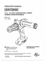
1/2 in., 19,2 VOLT CORDLESS DRULL-DRIVER
VARIABLE SPEED/REVERSIBLE
Model No.
315.115810
•t_ WARNING: To reduce the risk of injury,
the user must read and understand the
operator's manual before usingthis
product.
BATTERIES AND CHARGERS
SOLD SEPARATELY
Customer Help Line: 1-800-932-3188
Sears, Roebuck and Co., 3333 Beverly Rd., Hoffman Estates, IL 60179 USA
Visit the Craftsman web page: www.sears.com/craftsman
983000-880
"[0-_3-05 (REV_'00)
Save this manual for future reference
ONE-YEAR FULL WARRANTY ON CRAFTSMAN TOOL
If this Craftsman tool falls to give complete satisfaction within one year from date of purchase, RETURN IT TO ANY
SEARS STORE OR OTHER CRAFTSMAN OUTLET IN THE UNITED STATES FOR FREE REPLACEMENT.
tf this Craftsman tool is used for commercial or rental purposes, this warranty applies for only 90 days from the date of
purchase,
This warranty gives you specific legal rights, and you may also have other rights which vary from state to state,
Sears, Roebuck and Co., Dept. 817 WA, Hoffman Estates, IL 60179
This tool has many features for making its use more pleasant and enjoyable,, Safety, performance, and dependability have
been given top priority in the design of this product making it easy to maintain and operate,,
2
_
WARNING!
Read all instructions. Failureto follow
all instructions listed below may result fn electric
shock, fire and/or serious tnlury_ The term "power
toot" in all of the warnings listed below refers to your
mains-operated (corded} power too! or battery-operated (cordless) power tool.
SAVE THESE INSTRUCTIONS
WORK AREA SAFETY
[] Keep work area clean and well lit. Cluttered or dark
areasinvite accidents_
ml Do not operate power tools in explosive atmospheres, such as in the presence of flammable
liquids,gases or dust. Powertools createsparks
whichmay ignitethe dustor fumes_
[] Keep children and bystanders away while operating a power tool. Distractions can causeyouto lose
control,
ELECTRICAL
SAFETY
n Power tool plugs must match the outleL Never
modify the plug in any way. Do not use any adapter
plugs with earthed (grounded) power tools.
Unmodified piugs and matching outlets will reduce
risk of electric shock
[] Avoid body contact with earthed or grounded surfaces
such as pipes, radiators, ranges and refrigerators.
There is an Increased risk of electric shock tf your body
is earthed or grounded,,
[] Do not expose power tools to rain orwet conditions, Water entering a power tool will increase the risk
ul e_ectfic shock,
w Do not abuse the cord, Never use the cord for
carrying, pulling or unplugging the power tool. Keep
cord away from heat, oil, sharp edges or moving
parts. Damaged or entangled cords increase the risk
o'_elecl]tic shock.
[] When operating a power too! outdoors, use an extension cord suitable for outdoor use. Use of a cord suitable for outdoor use reduces the risk of electric shock.
[] Use battery only wffh charger listed.
MODEL
BATTERYPACK
CHARGER
315.1!5810
1302790D3
Mode] No. 1425301
130279005
(itemNo. g_11041)
(item No°9_11375)Mode_lNo. 315_115730
(item No. 140301003)
PERSONALSAFETY
[] Stay alert,watch what you are doing and use
commonsensewhen operaPJng
a powertool Do
not usea power tool while you are tired or under
the influenceof drugs, alcohol or medication, A
moment of inattention whileoperatingpowertools may
result in serious persona!in'}ury_
El Use safety equipment. Always wear eye protection.
Sa_eti equipment such as d_ mask, non-skid safety
shoes, hard hat, or hearing protection used for appropriate conditions wi[_ reduce personal i_juries_
ta Avoid accidental starting. Ensure the switch is in
the off-position before plugging in. Carrying power
tools with your finger on the switch or plugging in
power tools that have the switch on invites accidents.
[] Remove any adjusting key or wrench before turning
the power tool on. A wrench or a key left attached to
a rotating part of the power tool may result in personal
tnturyo
m Do not overreach. Keep proper footing and balance
at all times. This enables better con!to{ of the power
too}in unexpected situations°
IE Dress properly. Do not wear loose clothing or jewelry. Keep your hair, clothing and gloves away from
moving parts. Loose clothes, jewelry, or long hair can
be caught in moving parts.
[] if devices are provided for the connection of dust
extraction and collection facilities, ensure these are
connected and properly used. Use of these devices
can reduce dust-related hazards.
[] Do not wear loose clothing or jeweJry, Contain long
hair. Loose clothes, Jewetry, or long hair can be drawn
into air vents.
m Do not use on a ladder or unstable support. Stable
footing on a soitd surface enabJes better control of the
power too! in unexpected situations,,
POWER TOOL USE AND CARE
[] Do not force the powertool. Use the correctpower
tool for your application.The correct powertool wiU
do the jobbetter and sa_erat the rate for whichit was
designed.
i1 Do not use the power tool if the switch does not
turn it on and off, Any powertool thatcannotbe
controlled withti_eswitch is dangerousand must be
repaired.
[] Disconnectthe plug from the power source and]or
the battery pack from the power too_before making
any adjustments,changingaccessories, or storing
power tools, Suchpreventivesafety measuresreduce
the risk of starting the power toolaccidentally,
[] Store idle power tools out of the reach of children
and do not allow persons unfamiliarwith the power
tool or these instructionsto operate the powertool.
Powertooisare dangerous in the handsof untrained
users,,
[] Maintain power tools. Check for misalignment or
bindingof moving parts, breakage of parts, and any
other condition that may affect the power tool's
operation,if damaged, havethe power toot repaired
before use. Manyaccidents arecaused by poorly
maintained powe_tools.
Im Keep cutting toots sharp and clean, Property maintained cutting toots with sharp cuttingedges are less
likely to bind and are easierto control
1_Usethe power tool, accessoriesand tool bits
etco,
in accordance with these instructionsand in the
manner intendedfor the particulartype of power
tool, taking into accountthe working condffions
and the work to be performed.Use of the power
tool for operations different from those intended could
result in a hazardous situation,
BATTERY TOOL USE AND CARE
Ensure the switch is in the off position before inserting battery pack. Inserting the battery pack into
power tools that have the switch on invites accidents,
= Recharge only with the charger specified by the
manufacturer, A charger that is suitable for one type
of ba_.ery pack may create a risk of fire when used with
another battery pack°
II Use power tools only with specifically designated
battery packs. Use of any other battery packs may
create a risk of injury and f_re**
la When battery pack is not in use, keep it away from
other metal objects like paper clips, coins, keys,
nails, screws, or other small metal objects that can
la Use auxgiary handles suppliedwith the tool. Loss of
ccn_ro_can causepersonalin)_ry.
Hold tool by insulatedgrippingsurfaces when
performingan operation where the cutting tool may
contact hiddenwiring or its own cord. Contact with
a "l_e" wire will also make exposed metal par_sof the
too} "live" and shock the operator,,
m Know your power tool. Read operator's manual
carefully.Learn its applications and l'rmitafions, as
well as the specificpotentialhazards related to this
tool. Foflowingthis rulewillreducetheriskof electric
shock, fire, or serious injury,
el Always wear safety glasses with side shields.
Everydayglasseshave only impact resistant lenses.
They are NOT safety glasses. Followingthls rulewill
reduce the risk of eye injury,,
la Protect your lungs, Wear a face or dust mask if the
operationis dusty.Following this Tulewillreduce the
risk of serious personal [nJuryo
m Protect your hearing. Wear hearingprotection
during extendedperiods of operation. Followingthis
rule willreduce the risk of serious personal injury,
m Battery tools do not have to be plugged into an
electrical outlet;,therefore, they are ah_taysin
operating condition.Be aware of possiblehazards
when not usingyour battery tool or when changing
accessories. Following this rulev_tlreducethe r_skof
electric shock, fire, or seriouspersonal injury.
make a connectionfrom one terminal to another.
Shorting thebatteryterminalstogethermay cause
bums or a fire°
la Under abusiveconditions,liquidmay be ejected
from the battery, avoid contact. If contact accidentally occurs,/lush with water. If liquid contacts
eyes, additionallyseek medical help. Uquid ejected
from the battery may cause irritation or burns,
SERVICE
[] Have your power tool servicedby a qualified repair
person usingonly identicalreplacement parts.This
wifl ensurethatthe safety of the pow_ tool is maJntainedo
A
_j_ WARNING! To reducether_skof injury,user must
read instruction
manual
i
When servicinga power _oo_,use o_|y iderKdca|
replacement parts. Follow instructions in the Maintenance sectionof this manual Use of unauthorized
parts or failureto fol_owMaintenanceinstructions may
create a risk of shock or injury.
I_ Do not place battery tools or their batteries near
fire or heat. This will reduce the risk of explosion and
possibly injuPx'o
11 Never use a battery that has been dropped or
received a sharp blow, A damaged battery is subject
to explosion,, Properly dispose of a dropped or
damaged battery immediately,
E Batteries vent hydrogen gas and can explode in
the presence of a source of ignffion, such as a pilot
light. To reduce the risk of serious personal injury,
never use any cordless product in the presence of
open flame. An exploded battery can prope_ debris and
chemicals. If exposed, 1lush wfth water immediatelyo
[] Do not charge battery tool ]n a damp or wet
location. Following this rulewill reduce the risk of
electric shock_
m For best resutts_ your battery tool should be
charged {n a location where the temperature is
more than 50"F but less than 100"F. Do not store
outside or in vehlc|es.
m Under extreme usage or temperature conditions,
battery leakage may occur. If liquid comes In
contact with your skin, wash immediatei_y with
soap and water, then neutralize with lemon juice
or vinegar, if liquid gets into your eyes, flush them
with clean water for at least 10 minutes, then seek
immediate medical attention. Fotlowtncjthls rule wt]{
reduce the dsk of serious personal injury,
A
An extension cord should not be used unless
absolutely necessary° Use of improper extension cord
could result In a risk of fire and electric shock If
extension cord must be used, make sure;
WARNING! READAND UNDERSTANDALL
INSTRUCTIONS_Failureto follow all instructions
listed below, may resultin electric shock, fire
and/or serious personal injury,
a, That p_nson plug of extension cord are the
same number, size and shape as those of
p{ug on charger,
Before using battery charger, read all instructions
and oautionari markings in this manual, on batten2
charger, battery, and product using battery to prevent
m_suse of the products and possible Injury or damage°
_
b That extension cord is properly wired and in
good electrical condition; and
CAUT|ON: To reduce the risk o;_electric shock
c. That wire size is large enotJgh for AC ampere
rating of charger as specified below:
or damage to the charger and battery, charge
only nicker-cadmium rechargeabte batteries as
specifically designated on your charger. Other
types of batteries may burst, causing personaI
injury or damage.
Cord Length (Feet)
25'
50'
100'
Cord Size (AWG)
16
16
16
NOTE: AWG = Amerfcan Wire Gauge
Iw Do not use charger outdoors or expose to wet or
damp conditions. Water entering charger will increase
the risk of electric shock.
B Do not operate charger with a damaged cord or
plug, which could cause shorting and electdc shock if
damaged, have the charger replaced by an authorized
serviceman°
B Use of an attachment not recommended or sold
by the battery charger manufacturer may result in
a risk of fire, electric shock, or injury to persons.
Following this rule will reduce the risk of electric shock,
fire, or seflous personal lnjury_
la Do not operate charger if it has received a sharp
blow, been dropped, or otherwise damaged in any
way. Take it to an authorized serviceman for electrfcat
check to determine if the charger is in good working
order.
u Do not abuse cord or charger. Never use the cord to
carry the charger. Do net puli the charger cord rather
than the plug when disconnecting from receptacle.
Damage to the cord or charger could occur and create
an electric shock hazard. F_eptacedamaged cords
immediately,
Ig Make sure cord is located so that it will not
be stepped on, tripped over, come in contact
with sharp edges or moving parts or otherwise
subjected to damage or stress. This will reduce the
risk of accidental falls, which could cause injun2,and
damage to the cord, which coutd result in e_ectfic
shock.
la Do not disassemble charger. Take it to an authorized
serviceman when service or repair is required° Incorrect
reassembly may result in a risk of electdc shock or fire°
m Unplug charger from outlet before attempting any
maintenance or cleaning to Yeduce the risk of
electric shock_
IM Disconnect charger from the power supply when
not in use. This wtli reduce the risk of electric shock
or damage 1othe charger ff metal items shoutd fall into
the opening, _talso wilt help prevent damage to the
charger during a power surge,
m Risk of elec_c shock. Do not touch uninsulated
portion of output connector or uninsuiated battery
termir_aL
e Keep cord and charger from heat to prevent
damage to housing or internal parts.
I1 Save these instructions. Refer to them frequently
and use them to instruct others who may use this
tool. If you loan someone this tool, {Dan them these
instructions a%o to pre_ent misuse of the product and
possible Injury
m Do not let gasoline, oils, petroleum-based products,
etc. come in corrta_ with plastic parts. They contain
chemicals that can damage, weaken, or destroy plasttc_
,_
WARNING:
Some dust created by power sanding, sawing, grinding, drilling, and other construction activities
contains chemicals known to cause cancer, bir_h defects or other reproductive harm. Some examples of these
chemicals are:
• lead from lead-based palnts,
, cryslattine silica from bricks and cement and other masonry products, and
• arsenic and chromium from chemicalfy-trea'_ed lumber,
'(our risk from these exposures varies, depending on how often you do this type of work, To reduce your exposure
to these chemicals: work in a well ventilated area, and work with approved safety equipment, such as those dust
masks that are specially designed to filter out microscopic particles.
5
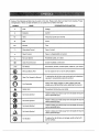
Some of the following symbols may be used on this tool. Please study them and learn their meaning.. Proper
interpretation of these symbols wil! allow you to operate the tool better and safer..
SYMBOL
DESIGNATION/EXPLANATION
NAME
V
Volts
Voltage
A
Amperes
Current
Hz
Hertz
Frequency (cycles per second)
W
Watt
Power
Minutes
Time
Alternating Current
Type of current
Direct Current
Type or a characteristic
rl o
No Load Speed
Rotational speed, at no load
[]
Class tl Construction
min
Double-insulated
of current
construction
iiii .................
._.!min
Per Minute
Revolutions, strokes, surlace speed, orbits etc., per minute
@
Wet Conditions Alert
Do not expose to rain or use in damp locations
Read The Operator's Manual
To reduce the risk of injury, user must read and understand
operator's manual before using this product,,
Eye Protection
Always wear safety goggles or safety glasses with side
shields and a full face shteld when operating this product.
Safety Alert
Precautions that involve your safety,
No Hands Symbol
Failure to keep your hands away from the blade will result in
serious personal injury.
No Hands Symbol
Failure to keep your hands away from the blade will result in
serious personal injury°
No Hands Symbol
Failure to keep your hands away from the blade will result in
serious personal injury,
No Hands Symbol
Failure to keep your hands away from the blade will result in
serious personal injury,,
Hot Surface
To reduce the risk of injury or damage, avoid contact with
any hot sufface,
@
,A
®
,&
®
Thefollowing
signal
wordsandmeanings
areintended
toexplain
thelevels
ofriskassociated
SYMBOL
SIGNAL
MEANING
A
DANGER:
Indicates an Imminently hazardous situation, which, tf not avoided, will
result in death or serious injury.
A
A
WARNING:
Indicates a potentially hazardous situation, which, if not avoided, could
result In death or serious Injury.
CAUTION:
Indicates a potentially hazardous situation, which, if not avoided, may
result in minor or moderate injury.
CAUTION:
(Without Safety Alert Symbol) Indicates a situation that may result in
property damage.
SERVICE
,_
Servicing requires extreme care and knowledge
and shou)d be performed only by a qualified service
technician. For service we suggest you return the product
to your nearest AUTHORIZED SERVICE CENTER for
repair, When servicing, use only identical replacement
parts.
,_
with this producK
WARNING: To avoid serious personal injury, do not
attempt to use this product until you read thoroughly
and understand cornpletety the operator's manual.
Save this operator's manual and review frequently for
continuing safe operaBon and instructing others who
may use this product,.
WARNING:
The operation of any power tool can result in foreign objects being thrown Into your eyes, which
can res_,_lLin severe eye damage_ Before beginning power tool o_eration, always wear saf:eLy
goggles or safety glasses with side shields and a full face shield when needed. We
recommend Wide Vision Safety Mask for use over eyeglasses or standard safety glasses with side
shields, Always use eye protection which is marked to comply with ANSI Z87,,1o
SAVE THESE nNSTRUCTIONS
PRODUCT SPECIFICATIONS
Chuck ...........................................................
Motor ...............................................................
t/2 in° Keyless
Clutch ................................................................... 24 Position
19.2 Volt DC
Torque .................................................... Maximum 420 in lb°
Switch .............................................................. Variable Speed
Charger Input ..................................... 1201/, 60 Hz, AC only
Gear Train ...........................................................................
2 Speed
Charge Rate ...........................................................................
1 hour
No Load Speed ..............................................
0-400/0-1,400/rain,
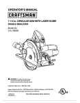
REARVIEW
TWO-SPEED
GEAR
TRAIN{UI-LO)
LEVEL
t{EYLESS
CHUCK
AUXILIARY
HANDLE
ASSEMBLY
SWITCH
TRIGGER
DIRECTION
OFROTATION
SELECTOR
(FORWARD!REVERSFJCENTER
LOCK)
SCREWDRIVER
BITS
LED
WORKUGHT
BIT
STORAGE
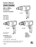
Fig.. 1
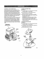
KNOW YOUR DRILL-DRIVER
See Figure 1.
LED WORKLIGHT
Before attempting to use this product, familiarize yourself
with aff operating features and safety rufes_
The LEDworkligh_;,
3oca_edon the front of the toolbase,
illuminateswhen the switch trigger isdepressed°This
provides extra fight for increasedvisibirity
AUXILIARY
LEVELS
HANDLE
Your ddll is equipped with an auxiliary handle for ease of
operation and to prevent loss of control_
Levels are located on the top and end of the motor
housing to hetp keep the drill bit level during use°
BIT STORAGE
TWO-SPEED GEAR TRAIN
Bits provided with the dflll-ddver can be placed in the
sLorage area, located on the base of the drill
The two-speed gear train Is designed for drilling or driving
at LO (1) or HI (2) speeds. A slide switch is located on top
of your drill for selectingeither LO (1) or HI (2) speed.
DIRECTION OF ROTATION SELECTOR
FORWARDtREVERSEiCENTER LOCK
Your drill has a direction of rotation (forward/reverse)
selector located above the switch tdgger for changing the
direction of bit rotation° Setting the switch trigger in the
OFF (center lock) posftion helps reduce the possibility of
accidental starting when not in use.
VARIABLE
SPEED
The variable speed switch trigger delivers higher speed
with increased trigger pressure and tower speed with
decreased trigger pressure.
KEYLESS CHUCK
The keyless chuck allows you to hand-tighten or release
the drill bit in the chuckjaws.
UNPACKING
A
This product has been shipped completely assembled.
B Carefully remove the toot and any accessories from the
box. Make sure that all items listed in the packing list
are included.
ml Inspect the tool carefully to make sure no breakage or
damage occurred during shipping,,
WARNING; Do not attempt to modify this tool
or create accessories not recommended for use
with this tool Any such alteration or modification is
m_suse and could result in a hazardous cond{tion
m Do not discard the packing material until you have
carefully inspected and satisfactorily operated _he toot.
= If any parts are damaged or missing, please call
1-80D-932-318B for assistance,
PACKING UST
1/2 in.Drill with Auxiliary Handle
Double-ended Bit (2)
Operator's Manual
WARNING: if any parts are damaged or missing do
not operatethis tooluntil the damaged or missing
parts are rep[acedoFailureto do so could resuftin
possible serious personal injury°
leading to possible serious personal Injury.
A
WARNING: To prevent accidental starting that
could cause serious persona! injury,always remove
the battery pack from the toot when assembling
parts.
A
,$L
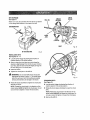
CHARGING A COOL BATTERY PACK
WARNING: Do not allow familiarity wffh too_s to
make you careless. Remember that a careless
fraction of a second is sufficient to inflict serious
injury.
_fbattery pack is below norton) temperature range, the
green LED on charger wil) come on. A_)ow battery pack to
reach normal temperature, then the red LED will come on.
NOTE: if the charger does not charge the battery pack
under normal circumstances, return both the battery pack
and charger to your nearest Sears Repair Center for
electrical checkr
A
WARNING: Always wear safety goggles or safety
glasses with side shields when operaLing tools°
Failure to do so could result in objects being thrown
into your eyes, resulting in possible serious Injury.
_
WARNING:
m Charge the battery pack only with the charger provfdedo
m Make sure the power supply is normal household
votLage, 420 volts, 60 Hz, AO onlyo
Do not use any attachments or
z_ Connect the charger to the power stJpplyo
accessories not recommended by the manufacturer
of tHs toot,. The use of attachments or accessories
not recommended can result in serious personal
injury.
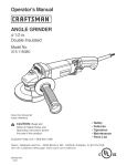
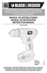
Place the battery pack in the charger aitgning raised rib
o# the battery pack with the groove in the charger. See
Figure 2.
[] Press down on the battery pack to be sure contacts on
the battery pack engage properly with contacts in the
charger,
APPLICATIONS
You may use this tool for the following purposes:
m Normat_y the red LED on charger will come on_This
indicates the charger is in fast charging mode
_l Drifting in wood
m Drilling in ceramics, plastics, fiberglass, and laminates
m Red LED should remain on for approximately 1 hour
then the green LED will come on_Green LED on
indicates battery pack is 1utly charged and charger is
in maintenance charge mode.
m Drilling in metals
Mixing paint
NOTE; The green LED will remain on until the battery
pack is removed from the charger or charger is
disconnected from the power supply.
CAUTION: If at any point during the charging
process none of the LEDs are lit, remove the battery
pack from the charger to avoid damaging the
product. DO NOT insert another battery° Return the
charger and battery to your nearest service center
for service or replacement,.
m If both yellow and green LEDs come on, thts indicates
a deeply discharged or defective battery pack. Allow
the battery pack to remain in the charger for 15 to 30
minutes. When the battery pack reaches normal
voltage range, the red LED should come on. ff the red
LED does not come on after 30 minutes, this may
indicate a defective battery pack and should be
replaced,.
LED FUNCTIONS OF CHARGER
LED WILL BE ON TO INDICATE
CHARGER AND BATTERY PACK:
STATUS OF
m After normal usage, a minimum of t hour of charging
time is required to fully recharge battery pack.
m Red LEDon = Fast chargingmode.
El Green LED on = Fully charged and in maintenance
chargemode.
[] Green LED on = When battery pack ls insertedInto
charger, Indicates hot battery pack or that battery pack
is out of normal temperature range.
[] The battery pack wilt become slightly warm to the
touch while charging. This is normal and does not
indicate a problem.
[] Do not place the charger and battery pack in an area
of extreme heat or cold. They will work best at normal
room temperature..
rollYellow and Green LEDs on = Deeply discharged or
deiectNe battery pack.
NOTE; The charger and battery pack should be placed
in a location where the temperature is more than 50"F
but less than 10D°F.
m NoLED on = Defective charger or battery pack.
CHARGING THE BATTERY PACK
m When batteries become fully charged, unplug the
charger from power supply and remove the battery
pack.
Battery packs for this tool are shipped In a low charge
condition to prevent possible problems. Therefore, you
should charge it until the green LED on the front of the
charger comes on.
NOTE; Batteries will not reach full charge the first time
they are charged° Allow severat cycles (operation followed
by recharging) for them to become fully charged.
t0
CHARGING A HOT BATTERY PACK
TO INSTALL
When using the toolcontinuously, the batteries in the
battery pack will become hot. You should let a hot battery
pack cool down for approximately 30 minutes before
attempting to recharge- When the battery pack becomes
discharged and is hot, this will cause the green LED to
come on instead of the red LED.. After 30 minutes, re]nsert
the battery pack in the charger_ if the green LED continues
to remain on, return battery pack to your nearest Sears
Repair Center for checking or replacing°
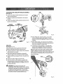
See Figure 3,
BATTERY PACK
u Lock switch trigger on the ddlf by placing the direction
of rotation selector In center position.
m Place battery pack in the ddIloAlign raised rib on
battery pack with groove inside ddtl,
lit Make sure the latches on each s_de of your battery
pack snap in place and battery pack is secured in drill
before beginning operation.
CAUTION," When placing battery pack in the dril!,
be sure raised rib on battery pack aligns with groove
]nslde dMItand latches snap into pJace properly,
Improper assembly o1 battery pack can cause damage
to internal components,
NOTE."This situation only occurs when continuous use of
the tool causes the batteries to become hoL ft does not
occur under normal circumstances, Refer to "Charging
a Cool Battery Pack" for normal recharging of batterfeso
if the charger does not charge your battery pack under
normal circumstances, return both the battery pack and
charger to your nearest Sears Repair Center for electrical
check°
TO REMOVE BATTERY PACK
See Figure 3,
Lock switch trigger on the ddl[ by placing the direction
of rotation selector in center position°
BATTERY
PACK
SHOWNtNCHARGER
a Locate latches on side of battery pack and depress to
release battery pack from the drill.
m Remove battery pack from the ddIL
REDLED
BATTERY
PACK
LATCHES
LED
Fig° 2
DEPRESS
LATCHES
TO
RELEASE
BATTERY
PACK
1I
Fig, 3
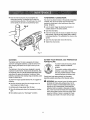
,_
WARNING: Battery tools are always in operating
condition° Therefore, switch should always be locked
when not in use or carrying at your side°
DIRECTION
OFROTATION
SELECTOR
(FORWARD
/ REVERSE
/
CENTER
REVERSE
To stop the ddll, release the switch trigger and allow the
chuck to come to a complete stop.
NOTE: The drill will not run unless the direction of rotation
selector is pushed futly to the left or dght,
Avoid running the drill at low speeds for extended pedods
of time, Running at low speeds under constant usage may
cause the drill to become overheated. If this occurs, cool
the drill by running it without a load and at full speed,
TWO-SPEED
GEAR TRA1N
See Figure 5.
SWITCff
TRIGBER
FORWARD
Fig°4
The drill has a two-speed gear train designed for drilling or
ddvlng at LO (I) or HI (2) speeds, A slide switch Is located
on top of the ddtl to select either LO (1} or HI (2) speed,
When using dr;I} in 1he LO (t) speed range, speed will
decrease and unit will have more power and torque_ When
using drill in the HI (2) speed range, speed will increase
and unit wilt have less power and torque, Use LO (1)
speed for htgh power and torque applications and HI (2)
speed for fast drilling or ddving applications.
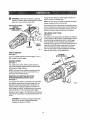
SWITCH TRIGGER
See Figure 4,
TWOSPEED
To turn the ddll ON, depress the switch trigger,To turn it
OFF, release the switch trigger.
GEARTRAIN(HI-L_,_
VARIABLE SPEED
See Figure4.
SPEED
The vadabiespeed switch delivers higher speedand
torque with increased trigger pressureand lowerspeed
with decreasedtrigger pressure.
NOTE; You might hear a whistling or tinging noise from
the switch during use, Do not be concerned; this is a
normal part of the switch function,
DIRECTION OF ROTATION SELECTOR
(FOWARDIREVERSE/CENTER LOCK]
See Figure4.
The direction of bit rotation is reversibleand is controlled
by a selector located abovethe switch tdgger_With the
drill held in normal operating posftion, the d_rectionof
rotation selector should be positioned to the left of the
switch trigger for drilling. The dffl]ing direction is reversed
when the selector Is to the dght of the switch trigger,
Setting the switch tdgger in the OFF (centerlock} position
helps reducethe possibility of accidental starting when not
In use.
CAUTION: To prevent gear damage, always allow
the chuck to come to a complete stop before
changing the direction of rotation°
12
LO
t SPEED
TO DECREASE
TORQUE
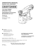
KEYLESS CHUCK
See Figure 6,
AI)JUSTING
FtlHG
The drill has a keyless chuck to tighten or release ddl]
bits in the chuck jaws. The arrows on the chuck indicate
which direction to rotate the chuck body In order to LOCK
(tighten} or UNLOCK (reTease)the driTIbiL
_
WARN|NG: Do not hold chuck body with one hand
and use power of the dri)) to tighten chuck jaws on
ddl] bit Chuck body could slip in your hand or your
hand could slip and come in contact with rotating
drill bit This could cause an accident resulting in
serious personal tnJuryo
DRILLBIT
%J
TO INCREASE
TORQUE
UNLOCK
(RELEASE)
Fig° 7
LED WORKLIGHT
See Figure 8.
The LED worklight on the foot of the ddli will come on
when the switch trigger is depressed. This provides
additional lighting on the surface of the workpiece for
operation in lower-light areas,
CHUCK
JAWS
LOCK
(_GHTEN)
Fig_6
ADJUSTABLE TORQUE CLUTCH
This product is equippedwith an adjustable torque
clutch for driving different types of screws into different
materials. Tl_epropersetting depends on the type of material and the size of screw you are using,
LED
WORKLIGHT
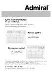
TO ADJUST TORQUE
See Figure 7.
m Thereare twenb/-fourtorqueIndfcatorsettings located
on the front ofthe dr/it.
m Rotate the adjusting ring to the desired settlng
• 1-4
For driving small screws
"
5"8
For driving screws into soft materiaI
•
9-I2
For driving screws into soft and hard
materials
°
I3-16
For driving screws into hard wood
t7-23
For driving large screws
For heavy dr_/ling
13
BIT STORAGE
See Figure9.
When not in use, bits provided with the drill can be placed
in the storage arealocatedon the base of the drill.
CHUCK
COLLAR
SCREWDRIVER
BIT
LOCI(
(TIGHTEN) CHUCK
BODY
RIGHT
Btf STORAGEAREA
INSTALLING
Fig° 10
Fig,9
BITS
See Figures 10 - 11.
Lock the switch trigger by placing the direction of
rotation selector in the center position_
u Open or close the chuck
opening is slightly larger
use° Also, raise the front
bit from falling out of the
jaws to a point where the
than the bit size you intend to
of the drill sfightty to keep the
chuck jaws.
u Insert the drill bit,
a Tighten the chuck Jaws on the drill bit,
•_k
WARNING:
Do not insert driP)bit }nto chuck Jaws
and _ighten as shown in ?ig_Jre11, This could cause
drill bit to be thrown from drift resulting in possible
sertotzs personal injury or damage to the chuck_
Fig. 1"/
REMOVING BITS
See Figure 40.
m Rotate the chuck clockwise to tighten the chuck )aws
securety on the bit,
= Lock the switch trigger by piecing the direction of
to,Lionselector inthe center posiLion,
NOTE: Rotate the chuck body in the direction of the
arrow marked LOCK to tighten the cL_ck {aws, Do r_ot
use a wrench to tighten or loosen the chuck iawso
eBRotate the cf_ucks(eev_ c{ockwise to open the cf_uck
iaws,
NOTE: Rotate the chuck body in the direction of the
arrow marked UNLOCK to loosen the chuck jaws, Do
not use a wrench to tighten or loosen the chuck jaws.
=1 Remove the drill bit.
14
ADJUSTING THE AUXILIARY
See P3gure I2.
HANDLE
LEVEL
ASSEMBLY
m Loosen the auyJliary handle assembly by turning the
knob counterdockwise,
B Rotate the auxiliary handle assembly to the desired
location°
u Tighten the auxiliary handle assembly securely by turning the knob c]ockwise_
TORQUE
AUXILIARY
ADJUSTMENT
R|NG
HAHDLE
ASSEMBLY
Fig. 13
360°
ROTATIOH
m When drilling hard, smooth surfaces, use a center
punch to mark the desired hole location. This will
prevent the drtll btt from slipping off-center as the hoJe
is started.
ia When drilling metals, use a light oil on the drill bit to
keep it from overheating. The otl will prolong the life of
the bit and increase the drilling action,.
Fig, 12
DRILLING
m If the bit jams in the workpiece or if the drill stalls,
stop the tool immediately, Remove the bit from the
workpiece and determine the reason for lamming.
NOTE: This drill has an electric brake, When the switch
trigger is released, the chuck stops turning. When the
brake is functioning property, sparks will be visible through
the vent slots on the housing. This is normal and is the
action of the brake.
See Figures 13 - 14.
Levels are located on the top and end of the motor
housing to help keep the drill bit level during use.
u Cheek the direction of rotation se[ector for the correct
setting (forward or reverse)_
Ell Secure the material to be drilled in a vise or with
clamps to keep it from t_Jming as the drill bit rota_es,
B Hold the drill firmly and place the bit at the point to be
dfiiledo
m Depresstheswitchtrigger
to start
thedrill
m Move theddflbitintotheworkpiece,applying
only
enough pressuretokeep thebltoutting_
Do notforce
the drill or apply side pressure to elongate a holeo Let
the too] do the work_
_
WARNING: Be prepared for bind}rig at bit
breakthrough. When these situations occur, drill has
a tendency to grab and kick opposite to the direction
of rotation and could cause loss of control when
breaking through material If not prepared, tNs loss
of control can result in possible serious injury°
15
MALLET
,_
WARNING:
When servicing, use only idenfica}
Craftsman replacement parts. Use of any other part
may create a hazard or cause product damage,
,_
WARNING:
A)ways wear sa_e_ygoggles or safety
glasses with side shields when using compressed air
to ctean tools if the operation is dusty, also wear a
dust mask,
._
WARNING:
To avoid serious persona! in)ury, aiways
remove the battery pack from the tool when cleaning
or performing any maintenance.
GENERAL
Fig. 15
MAINTENANCE
Avoid using solvents when cleaning plastic parts° Most
plastics are susceptible to damage from various types of
commercial so}vents and may be damaged by their use.
Use cIean cloths to remove dirt, dust, oil, grease, etc
,_
WARNING:
m Open the chuck jaws and remove the hex key. Using a
screwdriver, remove the chuck screw by turning it in a
clockwise direclion.
NOTE: The chuck screw has left hand threads.
Do not at any time tot brake fluids,
gasoline, petroleum-based products, penetrating
oils, etc,, come in contact with plastic parts,
Chemicals can damage, weaken or destroy plastic
which may result in serious personal injurySCREWDRIVER
\.,
Only the parts shown on the parts list are intended to be
repaired or replaced by the customer. All other parts
should be replaced at a Sears Service Center.
CHUCK
REMOVAL
See Figures 15 - t7,
The chuck may be removed and replaced by a new one.
[] Lock the switch trigger by placing the direction of
rotation selector in center position,
[] Insert a 5/16 in. or larger hex key into the chuck of the
dfllt and ttghten the chuck )_,vs secuTely.
[] Tap the hex key sharply with a mallet in a olock_wise
direction. This wit1loosen the screw in the chuck for
easy removal.
16
m Insert the hex key into the chuck and tighten the
chuck jaws securely. Tap sharply'_ith a mailer in a
counterclockwise direction. This will ioosen the chuck
TO RETIGHTEN
A LOOSE CHUCK
The chuck may become loose on the spindle and deveJop
a wobbte Also, the chuck screw may become loose,
causing the chuck jaws to bind and prevent them from
closing. To tighten:
on the spindle° It can now be unscrewed by hand.
m Lock the switch trigger by p_acing the direction of
rotation selector in the center position.
Open the chuck jaws.
m Insert the hex key _nto the chuck and tighten the chuck
jaws securely° Tap the hex key sharpJy with a mallet in
a clockwise direction. This will tighten the chuck on the
spindle.
el Open the chuck jaws and remove the he× key.
m Tighten the chuck screw.
Fig. 17
BATTERY PACK
FOR RECYCLING
BATTERIES
The battery pack for this tool is equipped with nickelcadmium rechargeable batteries. Length of service from
each charging will depend on the type of work you are
doing.
AND PREPARATION
recycle er dispose of batteries
properly°
The batteries in this tool have been designed to provide
maximum trouble-free life. However, like all batteries, they
will eventually wear out° Do net disassemble battery pack
and attempt to replace the batteries° Handling of these
batteries, especially when wearing tings and jewelry, could
result in a sedous burn.
This producL contains n[ckeFcadmium
To preserve
natura!
resources,
batteries.
Local,
state
or federalplease
(aws may prohibit disposal of n(ckefcadmium batteries in ordinary trash,
Consult your local waste authority for information
regarding avalfable recycling and/or disposal options,
To obtain the longest possible battery life, we suggest the
rot'lowing:
_,
WARNING:
Upon removal, cover the battery pack's
termfnats with heavy-duty adhesive tape, Do not
attempt to destroy or disassemble battery pack or
remove any of its components. Nickel-cadmium
batteries must be recycled or disposed of properly.
Also, never touch both terminals with metal objects
and/or body parts as short circuit may result. Keep
away from children_ Failure to comply with these
warnings coutd resutt in fire and/or serious injury,
Remove the battery pack from the charger once it is
fully charged and ready for use.
For battery pack storage longer than 30 days:
u Store the battery pack where the temperature is below
80°F.
ill Store battery packs in a "discharged"
REMOVAL
condition.
17
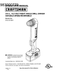
CRAFTSMAN
[ _
19=2 VOLT CORDLESS
DRILL-DRWER
MODEL
NO. 315.115810
model number will be lound on a plate attached to the motor housing_ Always mention the model
I
l,number in all correspondence regarding your CORDLESS DRILL-DRIVER or when ordering repair parts, J
SEE BACK PAGE FOR PARTS ORDERING
i i ....
INSTRUCTIONS
i -" i i"i!i !:!:i:!.............................................................
'.Jj
PARTS LIST
Key
No,
Part
Number
Description
t
6613402
Screw (Special)....................................................................................
1
2
690033066
Ohuck .....................................................................................................
1
3
940237117
Data Plate................................................................................................
1
4
300188028
Auxiliary Handle Assembly.......................................................
1
983000-880
Operator's Manual(not shown)
Qty.
18