1
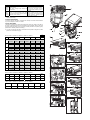
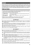
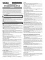
J E D F N Es I Dk C K R P
F19E10091
ELECTRONIC FLASH
EF-610 DG ST EO-ETTL II
ENGLISH
Thank you very much for purchasing the Sigma EF-610 ST EO-ETTL II Electronic
Flash. This product is specifically developed for the Canon EOS series SLR cameras.
Depending on the camera model, functions and operation may vary. Please read this
instruction booklet carefully. To add to your enjoyment of photography, the flash has a
variety of features. To make the most of all these features, and to get the maximum
performance and enjoyment from your flash, please read this instruction booklet,
together with your camera’s instruction manual, before using the flash, and also keep
it handy for your future reference.
PRECAUTIONS
Symbol denotes the important points, where warning and caution are required.
Symbol contains information regarding the actions that must be avoided.
Warning !!
Using the product disregarding this warning sign might cause serious injury or other dangerous results.
This flash contains high voltage circuits. To avoid electric shock or burns, do not
attempt to disassemble the flash. If the outside shell of the unit is broken or cracked,
do not touch the mechanism inside.
Do not fire the flash close to eyes. Otherwise the bright light could damage the eyes. Keep
at least 1m/3feet distance between face and the flash unit, when taking a picture with flash.
Do not touch the synchro terminal of your camera when the flash is attached to hot
shoe. High voltage circuitry could cause electric shock.
Never use your camera in an environment where flammable, burnable, gas, liquids or
chemicals, etc, exist. Otherwise, it might cause fire or explosion.
Caution!!
Using the product disregarding this caution sign might cause injury or damage.
Do not use this flash unit on any camera other than the Canon EOS series cameras;
otherwise the flash may damage the circuitry of these cameras.
This flash unit is not waterproof. When using the flash and camera in the rain or snow
or near water, keep it from getting wet. It is often impractical to repair internal electrical
components damaged by water.
Never subject the flash and camera to shock, dust, high temperature or humidity.
These factors might cause fire or malfunctioning of your equipment.
When the flash is subjected to sudden temperature change, as when the flash unit is
brought from a cold exterior to warm interior, condensation might form inside. In such
a case, place your equipment in a sealed plastic bag before such a change, and do
not use the flash unit, until it reaches room temperature.
Do not store your flash in a drawer or cupboard etc., containing naphthalene, camphor
or other insecticides. These chemicals will have negative effects on the flash unit.
Do not use a thinner, Benzene or other cleaning agents to remove dirt or finger prints
from the component. Clean with a soft, moistened cloth.
For extended storage, choose a cool dry place, preferably with good ventilation. It is
recommended that the flash be charged and fired several times a month, to maintain
proper capacitor functioning.
DESCRIPTION OF THE PARTS (fig.1)
1.Flash Head 2.AF Auxiliary Light 3.Shoe Ring 4.Shoe 5.Bounce Angle; Up and
Down
6.Swivel Lock and Release Button; Right and Left 7.Bounce Angle; Right and Left
8.Battery Cover 9.Flash Coverage Angle Indicator
10.Bounce Lock and Release Button; Up and Down 11.TEST Button 12.Ready Light
13.Power Switch 14.Catch Light Panel
15. Wide Panel
ABOUT THE BATTERY
This flash unit uses four “AA” type Alkaline dry cell batteries or Ni-Cad, Ni-MH,
rechargeable batteries. Manganese batteries can also be used but as they have a
shorter life than Alkaline batteries, we do not recommend using them. Please replace
batteries if it takes more than 30seconds to light the Ready Lamp.
■ To assure proper electrical contact, clean the battery terminals before installing the
batteries
■ NiCad batteries do not have standardized contacts. If you use NiCad batteries,
please confirm that the battery contacts touch the battery compartment properly.
■ To prevent battery explosion, leakage or overheating, use four new AA batteries of
the same type and brand. Do not mix the type or new and used batteries.
■ Do not disassemble or short-circuit batteries, or expose them fire or water; they
may explode. Also, do not recharge the batteries other than Ni-Cd rechargeable
batteries.
■ When the flash will not be used for an extended period of time, remove the
batteries from the flash, to avoid the possibility of damage from leakage.
■ Battery performance decreases at low temperatures. Keep batteries insulated when
using the flash in cold weather.
■ As with any flash, it is recommended you carry spare batteries when on a long trip,
or when photographing outdoors in cold weather.
BATTERY LOADING
1. Be sure to set the Power Switch to the off position then slide, the battery cover in
the direction of the arrow to open (fig.2).
2. Insert four AA size batteries into the battery chamber. Be sure the + and – ends of
the batteries are aligned according to the diagram in the chamber (fig.3).
3. Close the cover.
4. Slide the Power Switch to the ON position. After few seconds, the Ready Lamp will
light, indicating that the flash unit can be fired.
5. Please press the “Test Button” to be sure that the flash is working properly.
■ If the battery power is not sufficient, or if there is an electronic information error, the
flash coverage angle indicator will blink to indicate the condition.
ATTACHING AND REMOVING THE FLASH TO AND FROM THE
CAMERA
Be sure turn off the Power Switch. Then insert the Shoe Base into the hot shoe on the
camera and turn the Shoe Locking Ring until it is tight (fig.4)(fig.5).
■ When you attach or remove the flash, grasp the bottom of the flash to prevent
damage to the shoe foot and camera’s hot shoe.
■ If the camera’s built-in flash is set in up position, please close it before you attach
the flash unit.
■ To remove the flash, rotate the shoe-locking ring in the opposite direction of
◄LOCK mark, until it stops.
ETTL(TTL) AUTO FLASH
In the TTL AUTO Mode, the camera will control the amount of flash lighting to get the
appropriate exposure for the subject.
1. Set the camera’s mode to Full-AUTO Mode. (Usually □ Mode. If the camera
does not have □ Mode, set to P Mode.)
2. Slide the Power Switch to the TTL Position.
■ If the flash coverage angle indicator blinks when you turn on the power of your flash,
please make sure that the flash head bounce angle is adjusted to the normal (0˚)
position.
3. Focus onto the subject.
4. Press the shutter button after the flash is charged.
■ After a picture is taken, and the film receives appropriate exposure, the Ready
Lamp will blink. If the Ready Lamp does not blink, it indicates that the flash light
was not sufficient for that particular situation. Please retake the picture at a distance
closer to the subject.
■ The AF Auxiliary Light will turn on automatically as you focus on a dark area.
Note: Effective distance is up to about 0.7 to 9 meter (2.3-29.5 feet).
■ When the flash is fully charged, the flash mark will appear in the finder. If the
shutter is released before the flash is fully charged, the camera will take the picture
at a slow shutter speed, with no flash.
■ To conserve battery power, the flash unit automatically turns itself off when the flash
is not used within approximately 90seconds. To turn the flash on again, depress the
“TEST” button or the camera shutter button, halfway.
■ The flash will automatically set the Zoom Head position according to the focal
length of your lens.
■ Please refer to《chart.1》for the effective distance ranges.
USING FLASH IN OTHER CAMERA MODES (Except EOS700, 750, 850)
Shutter Speed Priority Setting
By selecting the Tv mode of the camera, you can set the shutter speed from 30sec. to
1/X sync speed. When you set the desired shutter speed, the camera will select the
appropriate aperture value for the background. If the subject is too light or too dark,
the aperture value indicator will blink and show the limit values (maximum or minimum
aperture). In such as case, the camera proceeds to take flash photograph at the limit
value. Thus, the main subject in the picture may be exposed correctly, but the
background will become under or over exposed.
Aperture Priority Setting
By selecting the Av mode of your camera, the camera will select the appropriate
shutter speed for the background. If the subject is too bright or too dark, the shutter
speed indicator will blink and show the limit highest or slowest shutter speed value.
The highest shutter speed will be limited to the camera’s normal flash synchronization
speed. In such a case, the camera proceeds to take a flash photograph at the limit
value. Thus, the main subject in a picture may be exposed correctly, but the
background will become under or overexposed.
When used with M Mode
You can set the desired shutter speed and aperture value. The sync speed of camera
is 30sec. If you adjust exposure according to the exposure meter indication, the
camera will work as for Daylight synchronization flash or slow synchronization.
MANUAL FLASH OPERATION (Except EOS700, 750, 850)
This flash unit can be used in Manual Mode at full power and at 1/16 power.
1. Set the camera’s exposure mode to Manual / M mode.
2. Slide the flash unit’s Power Switch to MH (full flash power) or to ML (1/16 flash
power).
3. Focus on the subject and set the camera’s F-stop, using the exposure calculated by
the formula shown below:
F-stop = Guide Number (G.N.) ÷ Flash to Subject Distance (m)
4. After the flash is fully charged, press he Shutter Release button to take the picture.
Guide Number will change according to the Zoom Head position, (see《chart.2》). Guide
Number will also change according to film speed (ISO),(see《chart.3》). In the case of
non-ISO100 speed films, multiply the《chart.3》number by the《chart.2》number. For
example, using ISO200 film, Zoom Head position for 24mm and the MH mode;
multiply the《chart.3》number ”1.4” by the《chart.2》number “34.0”: 34.0×1.4=47.6. This
will be the new effective Guide Number (G.N.) in meters. To determine the G.N. in feet,
multiply the G.N. in meters by 3.3.
EX. If flash to subject distance is 8.5 meters:
F-stop = 47.6 ÷ 8.5 = 5.6 (5.6 is the F-stop to set on the camera.)
When repeatedly using the flash rapidly in the MH mode, it should be allowed to “rest”
for about 10 minutes after each 20 flashes. If used under the same conditions in the
ML mode, the flash should be allowed to “rest” after each 40 flashes.
WIDE PANEL
This flashgun is equipped with a built-in wide panel, which can provide an ultra wide
17mm angle of coverage. Slide out the wide panel and catch light panel and flip it
down to cover the flash’s head (fig.6-1). (Be careful to slide the panels out smoothly.)
Then put the catch light panel back in its place (fig.6-2). The coverage angle setting of
the flash will be set to 17mm automatically.
■ The flash coverage angle indicator will show that the wide panel is in use by
blinking the both end values (24mm and 105mm) slowly (1sec each time).
■ If the built-in wide panel comes off accidentally, adjustment mechanism of flash
coverage angle will not function. In this case please contact the store where you
have purchased the flash, or a service station.
BOUNCE FLASH
When you take a photo with flash in a room, sometimes a strong shadow will appear
behind the subject, if you point the flash head upwards or sideways to reflect the light
off the ceiling, wall etc. the subject will be illuminated softly. Press the lock button and
adjust the flash head to set the bounce angle (fig.7).
UP: 0°, 60°, 75°, 90°
DOWN: 0°,7°
RIGHT: 0°, 60°, 75°, 90° LEFT: 0°, 60°, 75°,90°, 120°, 150°, 180°
■ Please refer to the following chart.
Bounce Flash (exclusive downward by 7°)
Zoom coverage angle will be set to the
50mm position.
The flash coverage angle display will
show 50mm.
Downward by 7°
Zoom coverage angle will change
depend on the zoom length of lens.
At that time, the display of zoom
coverage angle will blink (2 times /
second).
Zoom coverage angle will be set to
The zoom coverage angle will be set to
17mm position and both extreme
17mm and both extremes of the zoom
values of the zoom coverage angle
coverage angle display (24mm & 105mm),
display (24mm & 105mm) will be
will blink (1 time / second)
blink (2 times / second).
Without
Wide
Panel
With
Wide
Panel
■ The picture will receive the color from the reflecting surface. Please choose a white
surface for bouncing.
CLOSE-UP EXPOSURES
For bounce flash can be tilted 7° downward for close-ups. The Flash will be effective
only for the subjects 0.5 meter to 2 meters.
CATCH LIGHT PANEL
This flash is equipped with a built-in catch light panel, which can create a catch light in
the eyes of the subject when the bounce flash mode is activated. Slide out the wide
panel and catch light panel (fig.8-1), and then put wide panel back in its place (fig.8-2).
(Be careful to slide the panels out smoothly.)
■ To create a catch light effectively, tilt the flash head upward 90 degrees and take
pictures at a close distance (fig.9).
m
ft
《表 1》
《chart.1》
《Tabelle 1》
《Tableau 1》《tabel 1》《Tabla 1》
1.4
2.0
2.8
4.0
5.6
17mm
24mm
28mm
35mm
50mm
1.5-16.4
2.1-24.3
2.2-25.0
2.3-25.7
2.9-32.9
4.9-53.8
6.9-79.7
7.2-82.0
7.5-84.3
9.5-107.9
70mm
105mm
3.3-37.1 3.9-43.6
10.8-121.7
12.8-14
3.0
1.0-11.5
1.5-17.0
1.5-17.5
1.6-18.0
2.0-23.0
2.3-26.0 2.7-30.5
3.3-37.7
4.9-55.8
4.9-57.4
5.2-59.1
6.6-75.5
7.5-85.3
1.6-18.6 1.9-21.8
8.9-100.
1
0.7-8.2
1.1-12.1
1.1-12.5
1.1-12.9
1.5-16.4
2.3-26.9
3.6-39.7
3.6-41.0
3.6-42.3
4.9-53.8
5.2-61.0 6.2-71.5
0.7-5.8
0.8-8.5
0.8-8.8
0.8-9.0
1.0-11.5
1.1-13.0 1.3-15.3
2.3-19.0
2.6-27.9
2.6-28.9
2.6-29.5
3.3-37.7
3.6-42.7 4.3-50.2
0.7-4.1
0.7-6.1
0.7-6.3
0.7-6.4
0.7-8.2
0.8-9.3
2.3-13.5
2.3-20.0
2.3-20.7
2.3-21.0
2.3-26.9
2.6-30.5 3.3-35.8
8.0
11.0
16.0
22.0
1.0-10.9
0.7-2.9
0.7-4.3
0.7-4.4
0.7-4.5
0.7-5.8
0.7-6.5
2.3-9.5
2.3-14.1
2.3-14.4
2.3-14.6
2.3-19.0
2.3-21.3 2.3-24.9
0.7-7.6
0.7-2.1
0.7-3.1
0.7-3.2
0.7-3.3
0.7-4.2
0.7-4.7
2.3-6.9
2.3-10.2
2.3-10.5
2.3-10.8
2.3-13.8
2.3-15.4 2.3-18.0
0.7-1.4
0.7-2.1
0.7-2.2
0.7-2.3
0.7-2.9
0.7-3.3
2.3-4.6
2.3-6.9
2.3-7.2
2.3-7.5
2.3-9.5
2.3-10.8 2.3-12.5
0.7-1.0
0.7-1.5
0.7-1.6
0.7-1.6
0.7-2.1
0.7-2.4
2.3-3.3
2.3-4.9
2.3-5.2
2.3-5.2
2.3-6.9
2.3-7.9
2.3-9.2
0.7-1.1
0.7-1.1
0.7-1.1
0.7-1.4
0.7-1.6
0.7-1.9
2.3-3.6
2.3-3.6
2.3-3.6
2.3-4.6
2.3-5.2
2.3-6.2
70mm
105m
m
32.0
0.7-5.5
0.7-3.8
0.7-2.8
《表 2》《chart.2》
《Tabelle 2》
《Tableau 2》《tabel 2》《Tabla 2》
17mm
24mm
28mm
35mm
50mm
MH
23.0
34.0
35.0
36.0
46.0
52.0
61.0
ML
5.8
8.5
8.8
9.0
11.5
13.0
15.3
《表 3》
《chart.3》
《Tabelle 3》《Tableau 3》《tabel 3》《Tabla 3》
ISO25
ISO50
ISO200
ISO400
ISO800
ISO1600
ISO3
200
X0.5
X0.71
X1.4
X2
X2.8
X4
X5.7