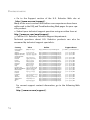
1
Wireless 54Mbps ADSL Router
User Guide
R46.1172.00
rev 3 10/05
Wireless 54Mbps ADSL Router
Installation ................................................................................ 3
Configuring the Wireless 54Mbps ADSL Router ......................... 7
Troubleshooting ...................................................................... 63
Specifications .......................................................................... 75
Regulatory ................................................................................81
Warranty.................................................................................. 85
CHAPTER 1
INSTALLATION
USR5473 Package Contents
USR9110 Wireless 54Mbps ADSL Router One (1) Ethernet cable
12VDC Power Supply
USR5422 54Mbps USB Adapter
Installation Guide One (1) phone cable Installation CD-ROM
Prepare for Installation
Note: It is important that you have your serial number written down
before you install the Wireless 54Mbps ADSL Router. You can find
your serial number on the bottom label of the Wireless 54Mbps ADSL
Router. If you ever need to call our Technical Support department, you will
need this number to receive assistance.
Model Number
Serial Number
USR9110
Note: Be sure to find out what letter your CD-ROM drives uses before
you begin installing your new product. You will need to know this to
properly install your software.
Step One: Connect Microfilter(s) (if included or required by your ISP)
A microfilter removes interference between voice and DSL signals. Your ISP
will determine if a microfilter is necessary. If a microfilter was not included
with the Wireless 54Mbps ADSL Router, ask your ISP if you need to purchase
one or more.
To install a microfilter, plug each device (phone, fax machine, or other
telephony device) into the microfilter and then plug the microfilter into the
telephone wall jack. Do not install a microfilter on the cable that will connect your Wireless 54Mbps ADSL Router to the telephone jack unless your
3
INSTALLATION
microfilter has a connection for both the router and the phone.
Step Two: Connect your Wireless 54Mbps ADSL Router to the wall phone
jack
• Turn off your computer.
• Connect one end of the included phone cable to the ADSL port on the
Wireless 54Mbps ADSL Router. Connect the other end of the phone cable
to a wall phone jack.
Step Three: Connect your Wireless 54Mbps ADSL Router to your computer
and connect the power supply
Connect one end of the supplied Ethernet cable to your computer’s Ethernet adapter. Connect the other end to the LAN port on the Wireless 54Mbps
4
ADSL Router.
Connect the included power adapter to the power socket on the Wireless
54Mbps ADSL Router. Plug the power adapter into a standard power outlet.
Turn on your computer.
’
Proceed to Chapter 2 to configure the Wireless 54Mbps ADSL Router.
5
INSTALLATION
6
CHAPTER 2
CONFIGURING THE WIRELESS
54MBPS ADSL ROUTER
To access the Wireless 54Mbps ADSL
Router’s Web User Interface, launch a Web
browser and type the default IP address of
the Wireless 54Mbps ADSL Router in
address line: http://192.168.2.1.
By default, there is no password, so click LOGIN to access the Web
User Interface.
If you are logging in to the Web User Interface for the first time, the
country selection page will appear. Please select the country in which
you will be using the Wireless 54Mbps ADSL Router and then click
Apply. Then confirm your country selection by clicking OK.
7
CONFIGURING THE WIRELESS 54MBPS ADSL ROUTER
Navigating the Web User Interface
This is the advanced setup page:
Setup Wizard: Use the Setup Wizard if you want to quickly set up the
Wireless 54Mbps ADSL Router. Go to “Setup Wizard” on page 9.
Advanced Setup: Advanced Setup supports more advanced functions
like hacker attack detection, IP and MAC address filtering, virtual
server setup, QoS, as well as other functions. Go to “Advanced
Setup” on page 20.
Making Configuration Changes
Configurable parameters have a text box or a drop-down list. Once a
configuration change has been made on a page, click SAVE SETTINGS or
NEXT at the bottom of the page to enable the new setting.
Note: To ensure the screen refreshes after a command entry, be
sure that Internet Explorer is configured as follows: Click Tools,
Internet Options, General, Temporary Internet Files, and Settings.
The setting for Check for newer versions of stored pages should be
Every visit to the page.
8
SETUP WIZARD
Setup Wizard
1. Begin the Setup Wizard
If this is the first time the Setup Wizard has been launched, select
your country and click Apply. Verify you have selected the correct
country and click OK.
Click NEXT.
2. Create a password for the router
Follow the on-screen instructions to create a password for access to
the router. Remember that there is no current password to enter.
After creating and confirming a password, click NEXT.
9
CONFIGURING THE WIRELESS 54MBPS ADSL ROUTER
3. Enter your wireless network and security information
You will see the Channel and SSID page. Enter the appropriate
information for your wireless and security settings. Refer to the table
that follows for descriptions of the different settings. Click NEXT
when done.
10
Parameter
Description
SSID
Service Set ID. The SSID must be the same on the Wireless
54Mbps ADSL Router and all of its wireless clients.
SSID Broadcast
Enable or disable the broadcasting of the SSID.
SETUP WIZARD
Parameter
Description
Wireless Mode
This device supports both 11g and 11b wireless networks. Make
your selection depending on the type of wireless network that you
have.
Security Type
For Security, you can select either No WEP, No WPA; WEP Only; or
WPA Only. If you select WEP or WPA, you will need to enter either
a Pass phrase or a Key on the next page.
Channel
The radio channel used by the wireless router and its clients to
communicate with each other. This channel must be the same on
the Wireless 54Mbps ADSL Router and all of its wireless clients.
The Wireless 54Mbps ADSL Router will automatically assign itself
a radio channel, or you may select one manually.
Click NEXT to continue.
4. Enter your Parameter Settings
Select the country of your Internet Service Provider (ISP) and the
name or type of your ISP. This will automatically configure the
Wireless 54Mbps ADSL Router with the correct Protocol,
Encapsulation and VPI/VCI settings for your ISP.
If your Country or Internet Service Provider is not listed, you will need
to manually enter the settings. Go to “Parameter Setting - Country or
ISP Not Listed” in this manual for more information. (It appears later
in this document.)
If your ISP uses PPPoA or PPPoE, then you will need to enter the
username, password and DNS Server address supplied by your ISP.
If your ISP uses 1483 Routing, then you will need to enter the IP
11
CONFIGURING THE WIRELESS 54MBPS ADSL ROUTER
address, Subnet Mask, Default Gateway and DNS Server address
supplied by your ISP.
Note: By default 192.168.2.1 is set for the DNS Server address,
this needs to be changed to reflect your ISP’s DNS Server
address.
Click NEXT to continue to the Confirm settings page.
Parameter Setting - Country or ISP Not Listed
If your Country or Internet Service Provider is not listed in the
dropdown menu, select Other. This will allow you to manually
configure your ISP settings.
For manual configuration you will need to know the Protocol, DNS
Server, Encapsulation, and VPI/VCI settings used by your ISP. If you
have a Static IP address you will also need to know the IP address,
Subnet Mask, and Gateway address. Please contact your ISP for
these details if you do not already have them.
After selecting Other you will be required to select the Protocol your
ISP uses from the Internet Service Provider dropdown list.
12
SETUP WIZARD
ISP uses Bridging - Parameter Setting
Enter the Bridging settings provided by your ISP.
Parameter
Description
Management IP Address
Enter the IP address provided by your ISP. (Default:
192.168.2.1)
VPI/VCI
Enter the Virtual Path Identifier (VPI) and Virtual
Circuit Identifier (VCI) supplied by your ISP.
Encapsulation
Select the encapsulation used by ISP from the
dropdown list.
Click NEXT to continue to the Confirm settings page.
13
CONFIGURING THE WIRELESS 54MBPS ADSL ROUTER
ISP uses 1483 Bridging-DHCP - Parameter Setting
Enter the Bridging settings provided by your ISP.
Parameter
Description
DNS Server
Enter the Domain Name Server address.
VPI/VCI
Enter the Virtual Path Identifier (VPI) and Virtual
Circuit Identifier (VCI) supplied by your ISP.
Encapsulation
Select the encapsulation used by ISP from the
dropdown list.
Click NEXT to continue to the Confirm settings page (see “5. Confirm
your settings” later in this document).
14
SETUP WIZARD
ISP uses 1483 Bridging-Fixed IP - Parameter Setting
Enter the bridging settings provided by your ISP.
Parameter
Description
IP Address
Enter the IP address provided by your ISP.
Subnet Mask
Enter the subnet mask address provided by your ISP.
Default Gateway
Enter the gateway address provided by your ISP.
DNS Server
Enter the Domain Name Server address.
VPI/VCI
Enter the Virtual Path Identifier (VPI) and Virtual
Circuit Identifier (VCI) supplied by your ISP.
Encapsulation
Select the encapsulation used by ISP from the
dropdown list.
Click NEXT to continue to the Confirm settings page (see “5. Confirm
your settings” later in this document).
15
CONFIGURING THE WIRELESS 54MBPS ADSL ROUTER
ISP uses PPPoE - Parameter Setting
Enter the PPPoE (Point-to-Point Protocol over Ethernet) settings
provided by your ISP.
Parameter
Description
VPI/VCI
Enter the Virtual Path Identifier (VPI) and Virtual
Circuit Identifier (VCI) supplied by your ISP.
Encapsulation
Select the encapsulation used by ISP from the
dropdown list.
Username
Enter the ISP assigned user name.
Password
Enter your password.
Confirm Password
Confirm your password.
Click NEXT to continue to the Confirm settings page (see “5. Confirm
your settings” later in this document).
16
SETUP WIZARD
ISP uses PPPoA - Parameter Setting
Enter the PPPoA (Point-to-Point Protocol over ATM) settings provided
by your ISP.
Parameter
Description
VPI/VCI
Enter the Virtual Path Identifier (VPI) and Virtual
Circuit Identifier (VCI) supplied by your ISP.
Encapsulation
Select the encapsulation used by ISP from the
dropdown list.
Username
Enter the ISP assigned user name.
Password
Enter your password.
Confirm Password
Confirm your password.
Click NEXT to continue to the Confirm settings page (see “5. Confirm
your settings” later in this document).
17
CONFIGURING THE WIRELESS 54MBPS ADSL ROUTER
ISP uses 1483 Routing - Parameter Setting
Enter the RFC1483 Routing settings provided by your ISP.
Parameter
Description
IP Address
Enter the IP address provided by your ISP.
Subnet Mask
Enter the subnet mask address provided by your ISP.
Default Gateway
Enter the gateway address provided by your ISP.
DNS Server
Enter the Domain Name Server address.
VPI/VCI
Enter the Virtual Path Identifier (VPI) and Virtual
Circuit Identifier (VCI) supplied by your ISP.
Encapsulation
Select the encapsulation used by ISP from the
dropdown list.
Click NEXT to continue to the Confirm settings page (see “5. Confirm
your settings”).
18
SETUP WIZARD
5. Confirm your settings
The Confirm page shows a summary of the configuration parameters.
Make sure the parameters for ADSL operation mode (WAN), Network
Layer Parameters (WAN), DHCP, and/or ISP parameters are correct
(see the following example).
Parameter
Description
ADSL Operation Mode
(WAN)
ISP
The type of ISP you have selected.
Protocol
Indicates the protocol used.
VPI/VCI
Virtual Path Identifier (VPI) and Virtual Circuit Identifier
(VCI).
AAL5 Encapsulation
Shows the packet encapsulation type. See the “WAN”
section later in this chapter for more information on
encapsulation.
Network Layer
Parameters (WAN)
IP Address
WAN IP address.
Subnet Mask
WAN subnet mask.
Default Gateway
WAN gateway.
19
CONFIGURING THE WIRELESS 54MBPS ADSL ROUTER
Parameter
Description
DHCP Parameters
Function
Shows the DHCP function is enabled or disabled.
Default Gateway
LAN IP address of the Wireless 54Mbps ADSL Router.
Subnet Mask
The network subnet mask.
Name Server 1
Primary DNS server IP address.
Name Server 2
Alternate DNS server IP address.
Start IP Address
Start IP address of DHCP pool of assigned IP addresses.
Number of IP
Number of IP addresses available for assignment by the
DHCP server.
If all the information is correct, click NEXT to complete the Setup
Wizard. You should now have Internet access. If any of the
information is not correct, click BACK to get to the appropriate
screen, modify the information, and then continue the configuration.
The information you supplied will be saved and the main screen of
the Web User Interface will appear.
If at any time you want to validate your Internet settings, click Status.
Advanced Setup
Click Home in the upper right-hand corner. The left-hand side of the
page displays the main menu and the right-hand side shows
descriptive information.
20
ADVANCED SETUP
The following table describes the main menu items on the advanced
Web User Interface.
Menu
Description
SYSTEM
Sets the local time zone, the password for administrator access, and
the IP address of a PC or notebook that will be allowed to manage the
Wireless 54Mbps ADSL Router remotely.
WAN
Specifies the Internet connection settings.
LAN
Sets the TCP/IP configuration for the Wireless 54Mbps ADSL Router
LAN interface and DHCP clients.
WIRELESS
Configures the radio frequency, SSID, and security for wireless
communications.
NAT
Configures Address Mapping, virtual server and special applications.
ROUTING
Sets the routing parameters and displays the current routing table.
FIREWALL
Configures a variety of security and specialized functions including:
Access Control, URL blocking, Internet access control scheduling,
intruder detection, and DMZ.
SNMP
Community string and trap server settings.
UPnP
With Universal Plug and Play, a device can automatically join a
network, obtain an IP address, communicate its capabilities, and learn
about the presence and capabilities of other devices. Devices can then
directly communicate with each other. This further enables peer-topeer networking.
QoS
Allows you to optimize network quality by prioritizing data traffic.
ADSL
Sets the ADSL operation type and shows the ADSL status.
21
CONFIGURING THE WIRELESS 54MBPS ADSL ROUTER
Menu
Description
DDNS
Dynamic DNS provides users on the Internet with a method to tie their
domain name to a computer or server.
TOOLS
Contains options to backup & restore the current configuration, restore
all configuration settings to the factory defaults, update system
firmware, or reset the system.
STATUS
Provides WAN connection type and status, firmware and hardware
version numbers, system IP settings, as well as DHCP, NAT, and firewall
information. Displays the number of attached clients, the firmware
versions, the physical MAC address for each media interface, and the
hardware version and serial number. Shows the security and DHCP
client log.
System
Time Settings
For accurate timing of log entries and system events, you need to set
the time zone. Select your time zone from the dropdown list.
If you want to automatically synchronize the Wireless 54Mbps ADSL
Router with a public time server, check the box to Enable Automatic
Time Server Maintenance. Configure two different time servers by
selecting a Primary Server and a Secondary Server.
22
ADVANCED SETUP
Password Settings
Use this page to change the password for accessing the Web User
Interface of the Wireless 54Mbps ADSL Router.
Passwords can contain from 3~12 alphanumeric characters and are
case-sensitive.
Note: If you lost the password, or you cannot gain access to the
Web User Interface, press in and hold the reset button on the
rear panel for at least five seconds to restore the factory defaults. By
default, there is no password to log in to the Web User Interface.
Enter a maximum Idle Time Out (in minutes) to define a maximum
period of time for which the login session is maintained during
inactivity. If the connection is inactive for longer than the maximum
idle time, it will perform a system logout and you will have to log in
again to access the Web User Interface. The default is 10 minutes.
Remote Management
By default, management access is only available to users on your
local network. However, you can also manage the Wireless 54Mbps
ADSL Router from a remote host by entering the IP address of a
remote computer on this screen. Select the Enabled checkbox, enter
23
CONFIGURING THE WIRELESS 54MBPS ADSL ROUTER
the IP address of the Host Address, and click SAVE SETTINGS.
Note: If you select Enable and specify an IP address of 0.0.0.0,
any remote host can manage the Wireless 54Mbps ADSL
Router.
For remote management via WAN IP address, you need to connect
using port 8080. Simply enter WAN IP address followed by :8080, for
example, 212.120.68.20:8080.
DNS
Domain Name Servers (DNS) are used to map a domain name
(e.g., www.somesite.com) with the IP address
(e.g., 123.123.123.123). Your ISP should provide the IP address of one
or more Domain Name Servers. Enter those addresses on this page
and click SAVE SETTINGS.
24
ADVANCED SETUP
WAN
Specify the WAN connection parameters provided by your Internet
Service Provider (ISP).
The Wireless 54Mbps ADSL Router can be connected to your ISP in
one of the following ways:
•
•
ATM PVC
Clone MAC
ATM PVC
Enter the ATM (Asynchronous Transfer Mode) virtual connection
parameters here.
Parameter
Description
Description
Click on the VC to set the values for the connection.
VPI/VCI
Virtual Path Identifier (VPI) and Virtual Circuit Identifier
(VCI).
25
CONFIGURING THE WIRELESS 54MBPS ADSL ROUTER
Parameter
Description
Encapsulation
Specifies how to handle multiple protocols at the ATM
transport layer.
Protocol
•
VC-MUX: Point-to-Point Protocol over ATM Virtual
Circuit Multiplexer (null encapsulation) allows
only one protocol running per virtual circuit with
less overhead.
•
LLC: Point-to-Point Protocol over ATM Logical Link
Control (LLC) allows multiple protocols running
over one virtual circuit (using slightly more
overhead).
Protocol used for the connection.
Clone MAC Address
Some ISPs require you to register your MAC address with them. If this
is the case, the MAC address of the Wireless 54Mbps ADSL Router
must be changed to the MAC address that you have registered with
your ISP.
26
ADVANCED SETUP
LAN
Use the LAN menu to configure the LAN IP address and to enable the
DHCP server for dynamic client address allocation.
Parameter
Description
LAN IP
IP Address
The IP address of the Wireless 54Mbps ADSL Router.
IP Subnet Mask
The subnet mask of the network.
DHCP Server
The Wireless 54Mbps ADSL Router comes with the DHCP
function. Enable this function to dynamically assign an IP address
to client PCs.
DHCP Server
DHCP Server ID
Specify the DHCP Server ID.
Lease Time
Set the IP lease time. For home networks this may be set to
Forever, which means there is no time limit on the IP address
lease.
27
CONFIGURING THE WIRELESS 54MBPS ADSL ROUTER
Parameter
Description
IP Address Pool
Start IP Address
Specify the start IP address of the DHCP pool. Do not include the
gateway address of the Wireless 54Mbps ADSL Router in the
client address pool. If you change the pool range, make sure the
first three octets match the gateway’s IP address, i.e.,
192.168.2.xxx.
End IP Address
Specify the end IP address of the DHCP pool.
Domain Name
If your network uses a domain name, enter it here. Otherwise,
leave this field blank.
Note: Remember to configure your client PCs for dynamic
address allocation.
Wireless
The Wireless 54Mbps ADSL Router also operates as a wireless access
point, allowing wireless computers to communicate with each other.
To configure this function, you need to enable the wireless function,
define the radio channel, the domain identifier, and the security
options. Select Enable and click SAVE SETTINGS.
Channel and SSID
You must specify a common radio channel and SSID (Service Set ID)
to be used by the Wireless 54Mbps ADSL Router and all of its
wireless clients. Be sure you configure all of the clients to the same
values.
28
ADVANCED SETUP
Parameter
Description
ESSID
Extended Service Set ID. The ESSID must be the same on the
Wireless 54Mbps ADSL Router and all of its wireless clients.
ESSID Broadcast
Enable or disable the broadcasting of the SSID.
Wireless Mode
This device supports both 11g and 11b wireless networks. Make
your selection depending on the type of wireless network that
you have.
Channel
The radio channel used by the wireless router and its clients to
communicate with each other. This channel must be the same on
the Wireless 54Mbps ADSL Router and all of its wireless clients.
The Wireless 54Mbps ADSL Router will automatically assign itself
a radio channel, or you may select one manually.
Access Control
The MAC Filtering feature of the Wireless 54Mbps ADSL Router allows
you to control access to your network for up to 32 clients based on
the MAC (Media Access Control) address of the client machine. This
ID is unique to each network adapter. If the MAC address is listed in
the table, then the access right of the client machine is controlled by
the Access Rule.
29
CONFIGURING THE WIRELESS 54MBPS ADSL ROUTER
Security
To make your wireless network safe, you should turn on the security
function. The Wireless 54Mbps ADSL Router supports WEP (Wired
Equivalent Privacy), WPA (Wi-Fi Protected Access), and 802.1x
security mechanisms.
30
ADVANCED SETUP
WEP
If you use WEP to protect your wireless network, you need to set the
same parameters for the Wireless 54Mbps ADSL Router and all your
wireless clients.
Parameter
Description
WEP Mode
Select 64 bit or 128 bit key to use for encryption.
Key Entry Method
Select Hex or ASCII code for encryption key generation.
Key Provisioning
Select Static if there is only one fixed key for encryption. If you
want to select Dynamic, you would need to enable 802.1x
function first.
31
CONFIGURING THE WIRELESS 54MBPS ADSL ROUTER
You may automatically generate encryption keys or manually enter
the keys. To generate the key automatically with passphrase, select
Passphrase and then enter a string of characters. Select the default
key from the dropdown menu. Click SAVE SETTINGS.
Note: The passphrase can consist of up to 32 alphanumeric
characters.
To manually configure the encryption key, enter five hexadecimal
pairs of digits for each 64-bit key, or enter 13 pairs for the single 128bit key. A hexadecimal digit is a number or letter in the range 0-9 or
A-F.
WEP protects data transmitted between wireless nodes but does not
protect any transmissions over your wired network or over the
Internet.
32
ADVANCED SETUP
WPA
Wi-Fi Protected Access (WPA) combines temporal key integrity
protocol (TKIP) and 802.1x mechanisms. It provides dynamic key
encryption and 802.1x authentication service.
Parameter
Description
Cypher suite
The security mechanism used in WPA for encryption.
Authentication
Choose 802.1X or Pre-shared Key to use as the authentication
method.
• 802.1X: for the enterprise network with a RADIUS server.
• Pre-shared key: for the Small Office/Home Office (SOHO)
network environment without an authentication server.
Pre-shared key type
Select the key type to be used in the Pre-shared Key.
Pre-shared Key
Type in the key here.
Group Key Re-Keying
The period of renewing broadcast/multicast key.
33
CONFIGURING THE WIRELESS 54MBPS ADSL ROUTER
802.1X
If 802.1x is used in your network, then you should enable this
function for the Wireless 54Mbps ADSL Router. These parameters are
used for the Wireless 54Mbps ADSL Router to connect to the
authentication server.
Parameter
Description
802.1X
Authentication
Enable or disable this authentication function.
Session Idle timeout Defines a maximum period of time for which the connection is
maintained during inactivity.
Re-Authentication
Period
Defines a maximum period of time for which the authentication
server will dynamically re-assign a session key to a connected
client.
Quiet Period
Defines a maximum period of time for which the Wireless 54Mbps
ADSL Router will wait between failed authentications.
Server Type
RADIUS authentication server.
RADIUS Server Parameters
Server IP
34
The IP address of your authentication server.
Server Port
The port used for the authentication service.
Secret Key
The secret key shared between the authentication server and its
clients.
NAS-ID
Defines the request identifier of the Network Access Server.
ADVANCED SETUP
NAT
Network Address Translation allows multiple users to access the
Internet, while sharing only one public IP.
Address Mapping
Allows one or more public IP addresses to be shared by multiple
internal users. This also hides the internal network for increased
privacy and security. Enter the Public IP address that you wish to
share into the Global IP field. In the from field, enter a range of
internal IPs that will share the global IP.
35
CONFIGURING THE WIRELESS 54MBPS ADSL ROUTER
Virtual Server
If you configure the Wireless 54Mbps ADSL Router as a virtual server,
remote users accessing services such as the Internet or FTP at your
local site via public IP addresses can be automatically redirected to
local servers with private IP addresses. In other words, depending on
the requested service (TCP/UDP port number), the Wireless 54Mbps
ADSL Router redirects the external service request to the appropriate
server (located at another internal IP address).
For example, if you set Type/Public Port to TCP/80 (HTTP or Web) and
the Private IP/Port to 192.168.2.2/80, then all HTTP requests from
outside users will be transferred to 192.168.2.2 on port 80. Therefore,
by just entering the IP address provided by the ISP, Internet users can
access the service they need at the local address to which you
redirect them.
A list of ports is maintained at the following link:
http://www.iana.org/assignments/port-numbers
36
ADVANCED SETUP
Special Applications
Some applications require multiple
connections, such as Internet gaming,
video-conferencing, and Internet
telephony. These applications may not
work when Network Address Translation
(NAT) is enabled. If you need to run applications that require multiple
connections, use these pages to specify the additional public ports to
be opened for each application.
37
CONFIGURING THE WIRELESS 54MBPS ADSL ROUTER
NAT Mapping Table
This page displays the current NAPT (Network Address Port
Translation) address mappings.
Routing
These pages define routing related parameters, including static
routes and RIP (Routing Information Protocol) parameters.
Static Route
Click Add to add a new static route to the list.
38
Parameter
Description
Network Address
Enter the IP address of the remote computer for which to set
a static route.
ADVANCED SETUP
Parameter
Description
Subnet Mask
Enter the subnet mask of the remote network for which to
set a static route.
Gateway
Enter the WAN IP address of the gateway to the remote
network.
Click SAVE SETTINGS to save the configuration.
RIP
RIP (Routing Information Protocol) sends routing-update messages at
regular intervals and when the network topology changes. When a
router receives a routing update that includes changes to an entry, it
updates its routing table to reflect the new route. RIP routers
maintain only the best route to a destination. After updating its
routing table, the router immediately begins transmitting routing
updates to inform other network routers of the change.
39
CONFIGURING THE WIRELESS 54MBPS ADSL ROUTER
Parameter
Description
General RIP Parameters
RIP mode
Globally enables or disables RIP.
Auto summary
If Auto summary is disabled, then RIP packets will
include sub-network information from all subnetworks connected to the router. If enabled, this
sub-network information will be summarized to one
piece of information covering all sub-networks.
Table of current Interface RIP parameter
Interface
The WAN interface to be configured.
Operation Mode
Disable: RIP disabled on this interface.
Enable: RIP enabled on this interface.
Silent: Listens for route broadcasts and updates its
route table. It does not participate in sending route
broadcasts.
Version
Sets the RIP version to use on this interface.
Poison Reverse
A method for preventing loops that would cause
endless retransmission of data traffic.
Authentication Required
Authentication Code
Routing Table
40
•
None: No authentication.
•
Password: A password authentication key is
included in the packet. If this does not match
what is expected, the packet will be discarded.
This method provides very little security as it is
possible to learn the authentication key by
watching RIP packets.
Password Authentication key.
ADVANCED SETUP
Parameter
Flags
Description
Indicates the route status:
C = Direct connection on the same subnet.
S = Static route.
R = RIP (Routing Information Protocol) assigned route.
I = ICMP (Internet Control Message Protocol) Redirect route.
Network
Address
Destination IP address.
Netmask
The subnetwork associated with the destination.
This is a template that identifies the address bits in the destination
address used for routing to specific subnets. Each bit that corresponds
to a “1” is part of the subnet mask number; each bit that corresponds to
“0” is part of the host number.
Gateway
The IP address of the router at the next hop to which frames are
forwarded.
Interface
The local interface through which the next hop of this route is reached.
Metric
When a router receives a routing update that contains a new or changed
destination network entry, the router adds 1 to the metric value indicated
in the update and enters the network in the routing table.
Firewall
The Wireless 54Mbps ADSL Router’s firewall inspects packets at the
application layer, maintains TCP and UDP session information,
including time-outs and the number of active sessions, and provides
the ability to detect and prevent certain types of network attacks.
Network attacks that deny access to a network device are called
Denial-of-Service (DoS) attacks. DoS attacks are aimed at devices
41
CONFIGURING THE WIRELESS 54MBPS ADSL ROUTER
and networks with a connection to the Internet. Their goal is not to
steal information, but to disable a device or network so users no
longer have access to network resources.
The Wireless 54Mbps ADSL Router firewall function protects against
the following DoS attacks: IP Spoofing, Land Attack, Ping of Death, IP
with zero length, Smurf Attack, UDP port loopback, Snork Attack, TCP
null scan, and TCP SYN flooding.
The firewall does not significantly affect system performance, so we
advise leaving it enabled to protect your network. Select Enable and
click SAVE SETTINGS to open the Firewall submenus.
Access Control
Access Control allows users to define the outgoing traffic permitted
or not permitted through the WAN interface. The default is to permit
all outgoing traffic.
The following items are on the Access Control screen:
Parameter
Description
Enable Filtering Function Click Yes to turn on the filtering function.
Normal Filtering Table
42
Displays the IP address (or an IP address range) filtering
table.
ADVANCED SETUP
To add the PC to the filtering table:
1. Click Add PC on the Access Control screen.
2. Define the appropriate settings for client PC services.
3. Click OK and then click SAVE SETTINGS to save your settings.
MAC Filter
The Wireless 54Mbps ADSL Router can also limit the network access
based on the MAC address. The MAC Filtering Table allows the
Wireless 54Mbps ADSL Router to enter up to 32 MAC addresses that
are allowed access to the WAN port.
43
CONFIGURING THE WIRELESS 54MBPS ADSL ROUTER
Click Yes to enable or No to disable this function.
Enter the MAC address in the space provided.
You can also select a client in the DHCP Client List and select the line
to which you want to copy the information.
URL Blocking
The Wireless 54Mbps ADSL Router allows the user to block access to
Web sites by entering either a full URL address or just a keyword.
This feature can be used to protect children from accessing violent or
pornographic Web sites.
44
ADVANCED SETUP
You can define up to 30 sites here.
Schedule Rule
You may filter Internet access for local clients based on rules. Each
access control rule may be activated at a scheduled time. Define the
time schedule on this page and apply the rule on the Access Control
page.
45
CONFIGURING THE WIRELESS 54MBPS ADSL ROUTER
Follow these steps to add a schedule rule:
1. Click Add Schedule Rule.
2. Define the appropriate settings for a schedule rule (as shown in
this example).
3. Click OK and then click SAVE SETTINGS to save your settings.
Intrusion Detection
Stateful Packet Inspection (SPI) and Anti-DoS firewall protection
(Default: Enabled) — The Intrusion Detection Feature of the Wireless
54Mbps ADSL Router limits access for incoming traffic at the WAN
port. When the SPI feature is turned on, all incoming packets will be
blocked except for those types marked in the Stateful Packet
Inspection section.
RIP Defect (Default: Disabled) — If an RIP request packet is not
acknowledged by the router, it will stay in the input queue and not be
released. Accumulated packets could cause the input queue to fill,
causing severe problems for all protocols. Enabling this feature
prevents the packets from accumulating.
Discard Ping to WAN (Default: Disabled) — Prevent a ping on the
Wireless 54Mbps ADSL Router’s WAN port from being routed to the
network.
46
ADVANCED SETUP
Scroll down to view more information.
47
CONFIGURING THE WIRELESS 54MBPS ADSL ROUTER
•
Stateful Packet Inspection
This is called a “stateful” packet inspection because it examines the
contents of the packet to determine the state of the communications;
i.e., it ensures that the stated destination computer has previously
requested the current communication. This is a way of ensuring that
all communications are initiated by the recipient computer and are
taking place only with sources that are known and trusted from
previous interactions. In addition to being more rigorous in their
inspection of packets, stateful inspection firewalls also close off ports
until connection to the specific port is requested.
When particular types of traffic are checked, only the particular type
of traffic initiated from the internal LAN will be allowed. For example,
if the user only selects FTP Service in the Stateful Packet Inspection
section, all incoming traffic will be blocked except for FTP
connections initiated from the local LAN.
Stateful Packet Inspection allows you to select different application
types that are using dynamic port numbers. If you wish to use the
Stateful Packet Inspection (SPI) to block packets, select Yes in the
Enable SPI and Anti-DoS firewall protection field and then select the
48
ADVANCED SETUP
inspection type that you need, such as Packet Fragmentation, TCP
Connection, UDP Session, FTP Service, H.323 Service, or TFTP
Service.
•
When hackers attempt to enter your network, we can alert you by
e-mail
If the mail server needs to authenticate your identification before
sending out any e-mail, please fill in the necessary information in the
POP3 server, username and password fields. Otherwise leave the
three fields blank.
•
Connection Policy
Enter the appropriate values for TCP/UDP sessions as described in
the following table:
Parameter
Defaults
Description
Fragmentation halfopen wait
10 sec
Configures the number of seconds that a packet
state structure remains active. When the timeout
value expires, the router drops the unassembled
packet, freeing that structure for use by another
packet.
TCP SYN wait
30 sec
Defines how long the software will wait for a TCP
session to synchronize before dropping the
session.
TCP FIN wait
5 sec
Specifies how long a TCP session will be
maintained after the firewall detects a FIN packet.
TCP connection idle
timeout
3600 sec
(1 hour)
The length of time for which a TCP session will be
managed if there is no activity.
UDP session idle
timeout
30 sec
The length of time for which a UDP session will be
managed if there is no activity.
H.323 data channel
idle timeout
180 sec
The length of time for which an H.323 session will
be managed if there is no activity.
49
CONFIGURING THE WIRELESS 54MBPS ADSL ROUTER
•
DoS Detect Criteria
Set up DoS detect and port scan criteria in the spaces provided.
Parameter
Defaults
Description
Total incomplete
TCP/UDP sessions
HIGH
300
sessions
Defines the rate of new unestablished sessions
that will cause the software to start deleting halfopen sessions.
Total incomplete
TCP/UDP sessions
LOW
250
sessions
Defines the rate of new unestablished sessions
that will cause the software to stop deleting halfopen sessions.
Incomplete TCP/UDP
sessions (per min)
HIGH
250
sessions
Maximum number of allowed incomplete
TCP/UDP sessions per minute.
Incomplete TCP/UDP
sessions (per min)
LOW
200
sessions
Minimum number of allowed incomplete
TCP/UDP sessions per minute.
Maximum incomplete
TCP/UDP sessions
number from same
host
10
Maximum number of incomplete TCP/UDP
sessions from the same host.
Incomplete TCP/UDP
sessions detect
sensitive time period
300
msec
Length of time before an incomplete TCP/UDP
session is detected as incomplete.
Maximum half-open
fragmentation packet
number from same
host
30
Maximum number of half-open fragmentation
packets from the same host.
Half-open
fragmentation detect
sensitive time period
10000
msec
Length of time before a half-open fragmentation
session is detected as half-open.
Flooding cracker block 300 sec
time
Length of time from detecting a flood attack to
blocking the attack.
Note: The firewall does not significantly affect system
performance, so we advise enabling the prevention features to
protect your network.
DMZ
If you have a client PC that cannot run an Internet application
properly from behind the firewall, you can open the client up to
unrestricted two-way Internet access. Enter the IP address of a DMZ
(Demilitarized Zone) host on this screen. Adding a client to the DMZ
50
ADVANCED SETUP
may expose your local network to a variety of security risks, so be
careful when using this option.
SNMP
Use the SNMP configuration screen to display and modify
parameters for the Simple Network Management Protocol (SNMP).
Community
A computer attached to the network, called a Network Management
Station (NMS), can be used to access this information. Access rights
to the agent are controlled by community strings. To communicate
with the Wireless 54Mbps ADSL Router, the NMS must first submit a
valid community string for authentication.
51
CONFIGURING THE WIRELESS 54MBPS ADSL ROUTER
Parameter
Description
Community
A community name authorized for management access.
Access
Management access is restricted to Read Only (Read) or
Read/Write (Write).
Valid
Enables/disables the entry.
Note: Up to five community names may be entered.
Trap
Specify the IP address of the NMS to notify when a significant event
is detected by the agent. When a trap condition occurs, the SNMP
agent sends an SNMP trap message to any NMS specified as a trap
receiver.
52
ADVANCED SETUP
Parameter
Description
IP Address
Traps are sent to this address when errors or specific events occur on
the network.
Community
A community string (password) specified for trap management. Enter a
word, something other than public or private, to prevent unauthorized
individuals from accessing information on your system.
Version
Sets the trap status to disabled, or enabled with V1 or V2c.
The v2c protocol was proposed in late 1995 and includes enhancements
to v1 that are universally accepted. These include a get-bulk command
to reduce network management traffic when retrieving a sequence of
MIB variables, and a more elaborate set of error codes for improved
reporting to a Network Management Station.
53
CONFIGURING THE WIRELESS 54MBPS ADSL ROUTER
UPnP
Select Enable to activate the Universal Plug and Play function of the
router. This function allows the device to:
•
dynamically join a network
•
automatically obtain an IP address
ADSL
ADSL (Asymmetric Digital Subscriber Line) is designed to deliver
more bandwidth downstream (from the central office to the customer
site) than upstream. This section is used to configure the ADSL
operation type and shows the ADSL status.
Parameters
54
ADVANCED SETUP
Parameter
Operation Mode
Description
•
Automatic
•
T1.413 issue 2
•
G.992.1 (G.DMT)
•
G.992.2 (G.Lite)
•
G.992.3 (ADSL2)
•
G.992.5 (ADSL2+)
This page is designed for the engineer to test the ADSL loop
condition. Therefore, it is advised that users should not change the
settings here at all.
Status
The Status screen displays information on connection line status,
data rate, operation data and defect indication, and statistics.
55
CONFIGURING THE WIRELESS 54MBPS ADSL ROUTER
The following items are included on the ADSL status page:
Parameter
Description
Status
Line Status
Shows the current status of the ADSL line connection.
Link Type
Two types of link: Fast path and Interleaved path.
Data Rate
Upstream
Maximum upstream data rate.
Downstream
Maximum downstream data rate.
Operation Data/Defect Indication
Noise Margin
Maximum upstream and downstream noise margin.
Attenuation
Maximum reduction in the strength of the upstream and
downstream signal.
Fast Path FEC
Correction
There are two latency paths that may be used: fast and
interleaved. For either path, a forward error correction (FEC)
scheme is employed to ensure higher data integrity. For
maximum noise immunity, an interleaver may be used to
supplement FEC.
Interleaved Path
FEC Correction
An interleaver is basically a buffer used to introduce a delay,
allowing for additional error correction techniques to handle
noise. Interleaving slows the data flow and may not be optimal
for real-time signals such as video transmission.
Fast Path CRC Error The number of Fast Path Cyclic Redundancy Check errors.
Interleaved Path
CRC Error
The number of Interleaved Path Cyclic Redundancy Check
errors.
Loss of Signal
Defect
Momentary signal discontinuities.
Fast Path HEC Error Fast Path Header Error Concealment errors.
Interleaved Path
HEC Error
Statistics
56
Interleaved Path Header Error Concealment errors.
(Superframes represent the highest level of data presentation.
Each superframe contains regular ADSL frames, one of which is
used to provide superframe synchronization, identifying the
start of a superframe. Some of the remaining frames are also
used for special functions.)
Received cells
Number of cells received.
Transmitted cells
Number of cells transmitted.
ADVANCED SETUP
DDNS
Dynamic DNS (DDNS) provides users on the Internet with a way to tie
their domain name to a computer or server. By enabling this, your
domain name will be linked to your IP address so that if your IP
address changes, your DNS records will be automatically updated
with the new location without any effort on your part. (This is done by
a DDNS provider.)
If you enable this feature, you will need to select a DDNS provider
and enter the site’s Domain Name, your account or e-mail address,
and your password or key. When finished, click SAVE SETTINGS.
Tools
Use the Tools menu to back up the current configuration, restore a
previously saved configuration, restore factory settings, update
firmware, and reset the Wireless 54Mbps ADSL Router.
Configuration Tools
Select a function and click Next.
57
CONFIGURING THE WIRELESS 54MBPS ADSL ROUTER
Backup allows you to save the Wireless 54Mbps ADSL Router’s
configuration to a file. Restore can be used to restore the saved
backup configuration file. Restore to Factory Defaults resets the
Wireless 54Mbps ADSL Router to the original settings.
You will be asked to confirm your decision.
Firmware Upgrade
Use the Firmware Upgrade screen to update the firmware or Web
User Interface to the latest versions. Download the upgrade file, and
save it to your hard drive. Click Browse to look for the downloaded
file and then click BEGIN UPGRADE. Check the Status page
Information section to confirm that the upgrade process was
successful.
58
ADVANCED SETUP
Reset
Click REBOOT ROUTER to reset the Wireless 54Mbps ADSL Router.
If you perform a reset from this page, the configurations will not be
changed back to the factory default settings.
Note: If you press the Reset button on the rear panel for one to
two seconds, the Wireless 54Mbps ADSL Router will perform a
power reset. Press the button for over five seconds and the factory
default settings will be restored.
59
CONFIGURING THE WIRELESS 54MBPS ADSL ROUTER
Status
The Status page displays WAN/LAN connection status, firmware, and
hardware version numbers, and illegal attempts to access your
network, as well as information on DHCP clients connected to your
network. The security log may be saved to a file by clicking Save and
choosing a location.
60
ADVANCED SETUP
The following items are included on the Status page:
Parameter
Description
INTERNET
Displays WAN connection type and status.
GATEWAY
Displays system IP settings, as well as DHCP Server and Firewall
status.
INFORMATION
Displays the number of attached clients, the firmware versions,
the physical MAC address for each media interface and for the
Wireless 54Mbps ADSL Router, as well as the hardware version
and serial number.
ATM PVC
Displays ATM connection type and status.
Disconnect
Click on this button to disconnect from the ATM connection.
Connect
Click on this button to establish a connection to the ATM
connection.
Security Log
Displays illegal attempts to access your network.
Save
Click on this button to save the security log file.
Clear
Click on this button to delete the access log.
Refresh
Click on this button to refresh the screen.
DHCP Client Log
Displays information on DHCP clients on your network.
61
CONFIGURING THE WIRELESS 54MBPS ADSL ROUTER
62
APPENDIX A
TROUBLESHOOTING
This section describes common problems you may encounter and
possible solutions to them. The ADSL Router can be easily monitored
through panel indicators to identify problems.
The Power LED is not illuminated.
Possible Solution
Check connections between the ADSL Router, the external power
supply, and the wall outlet.
Possible Solution
If the power indicator does not turn on when the power cord is
plugged in, you may have a problem with the power outlet, power
cord, or external power supply. However, if the unit powers off after
running for a while, check for loose power connections, power losses,
or surges at the power outlet.
If you still cannot isolate the problem, then the external power supply
may be defective. In this case, contact Technical Support for
assistance.
The Link LED is not illuminated.
Possible Solution
Verify that the ADSL Router and attached device are powered on.
Be sure the cable is plugged into both the ADSL Router and the
corresponding device.
Possible Solution
Verify that the proper cable type is used and that its length does not
63
TROUBLESHOOTING
exceed the specified limits.
Possible Solution
Be sure that the network interface on the attached device is
configured for the proper communication speed and duplex mode.
Possible Solution
Check the adapter on the attached device and cable connections for
possible defects. Replace any defective adapter or cable if necessary.
I cannot ping the ADSL Router from the attached LAN.
Possible Solution
Verify that the IP addresses are properly configured. For most
applications, you should use the ADSL Router’s DHCP function to
dynamically assign IP addresses to hosts on the attached LAN.
However, if you manually configure IP addresses on the LAN, verify
that the same network address (network component of the IP
address) and subnet mask are used for both the ADSL Router and any
attached LAN devices.
Possible Solution
Be sure the device you want to ping (or from which you are pinging)
has been configured for TCP/IP.
I cannot connect to the Internet.
Possible Solution
Be sure you have configured the ADSL Router with the correct DSL
connection information that was supplied by your ISP.
Possible Solution
Make sure that the power cord and all the Ethernet cables are
connected correctly. This includes the cables connecting the Wireless
54Mbps DSL Router and all the computers.
64
TROUBLESHOOTING
Possible Solution
Check the network cabling between the computer and the ADSL
Router.
I forgot or lost the password for the Wireless 54Mbps ADSL Router.
Possible Solution
Press the Reset button on the rear panel for at least five seconds to
restore the factory defaults.
A wireless client cannot associate with the ADSL Router.
Possible Solution
Make sure the wireless client has the same SSID settings as the ADSL
Router.
Possible Solution
You need to have the same security settings on the clients and the
ADSL Router.
The ADSL Router cannot be detected by a wireless client.
Possible Solution
The distance between the ADSL Router and wireless PC may be too
great. Make sure the wireless client has the same SSID and security
settings as the ADSL Router.
I cannot access the router’s Web User Interface.
Possible Solution:
Make sure that the power cord and all the Ethernet cables are connected correctly. This includes the cables connecting the Wireless
54Mbps DSL Router and all the computers.
Possible Solution:
65
TROUBLESHOOTING
Make sure that your computer is using an IP address that is within
the default range of 192.168.2.xxx. Make sure the address of the subnet mask is 255.255.255.0. The Default Gateway should be the IP
address of the Wireless 54Mbps DSL Router, which is 192.168.2.1.
Possible Solution:
You need to verify the connection setting of your Web browser and
that the HTTP Proxy feature of your Web browser is disabled. You
need to do this so that your Web browser can read the configuration
pages inside your Wireless 54Mbps DSL Router. Launch your Web
browser.
Internet Explorer users: Click Tools, Internet Options, and then the
Connections tab. Select Never dial a connection, click Apply, and
then click OK. Click Tools again, then click Internet Options. Click the
Connections tab, and click the LAN Settings button. Clear all the
check boxes and click OK. Click OK to close Internet Options.
Netscape Navigator users: Click Edit, Preferences, and then doubleclick Advanced in the Category window. Click Proxies, select Direct
connection to the Internet, and then click OK. Click Edit again, then
click Preferences. Under Category, double-click Advanced, then click
Proxies. Select Direct connection to the Internet and click OK.
I am no longer able to access the Internet through the Wireless
54Mbps DSL Router.
Possible Solution:
Make sure that the power cord, the DSL cable, and the Ethernet cable
are all connected correctly.
Possible Solution:
Make sure that your computer is using an IP address that is within
the default range of 192.168.2.xxx. Make sure the address of the subnet mask is 255.255.255.0. The Default Gateway should be the IP
address of the Wireless 54Mbps DSL Router, which is 192.168.2.1. To
66
TROUBLESHOOTING
verify all of these settings, perform the following steps:
Windows 95, 98, or Me Users: Click Windows Start and then
Run. Type winipcfg and click OK. Check the IP Address, Subnet
Mask, Default Gateway, and DNS server data to make sure they
are correct. If the information is not correct, click Release All and
then click Renew All.
Windows NT, 2000, or XP Users: Click Windows Start and then
Run. Type cmd and click OK. At the DOS prompt, type ipconfig
/all. Check the IP Address, Subnet Mask, Default Gateway, and
DNS server data to make sure they are correct. If the information
is not correct, type ipconfig /release and press ENTER. Then,
type ipconfig /renew and press ENTER.
My Web User Interface for the Wireless 54Mbps DSL Router is not
responding, but I can still access the Internet.
Possible Solution:
If your Web User Interface stops responding, unplug and then plug
back in the power supply of the Wireless 54Mbps DSL Router. This
will reboot the Wireless 54Mbps DSL Router. If you are still unable to
communicate with the router’s Web User Interface, use a paperclip to
press in and hold the RESET button for five seconds. This will reset
the Wireless 54Mbps DSL Router to the factory default settings. If
you applied any personal configuration settings, you will need to
make the changes again.
I am unable to connect to the wireless function of the Wireless
54Mbps DSL Router.
Possible Solution:
Be certain that you have each Wireless adapter is set to Infrastructure mode. If your 802.11g 54Mbps USB Adapter is set to Ad hoc
mode, you will not be able to use the wireless function. Refer to the
documentation that came with your wireless adapter to determine
how to change this setting.
67
TROUBLESHOOTING
Note: Ad hoc mode is used for peer-to-peer network configurations.
Infrastructure mode is used for integrated wireless and wired LAN
configuration.
My computer does not recognise the wireless function of the Wireless 54Mbps DSL Router after I changed the settings.
Possible Solution:
Ensure that you are connecting to the correct Wireless 54Mbps DSL
Router by verifying the correct MAC address. Ensure that the correct
passphrase and encryption option is being used. If you changed the
settings in the configuration of the Wireless 54Mbps DSL Router, you
must also change the settings of every Wireless adapter attached to
this network. The settings of the Wireless adapters must match the
new settings of the Wireless 54Mbps DSL Router.
I cannot achieve 54 Mbps connections to the Wireless 54Mbps DSL
Router.
Possible Solution:
Make sure the wireless products you are using to connect to the
Wireless 54Mbps DSL Router support 54 Mbps speeds. 54 Mbps
wireless products must be used in order to connect to the Wireless
54Mbps DSL Router at a rate of 54 Mbps. Launch the router’s Web
User Interface and manually set the connection speed to 54 Mbps. If
you are using non-U.S. Robotics wireless products, you may need to
upgrade the firmware for those products in order to support 54 Mbps
connections.
Possible Solution:
Low connection speed or range can also be caused by environmental
interference. Try to move the product around to improve the link
quality. In addition, keep in mind that other factors such as lead
68
TROUBLESHOOTING
based paint, concrete walls, and electronic items such as 2.4G
phones may affect your wireless range.
I plugged in the 802.11g 54Mbps USB Adapter but I do not see the
Configuration Utility icons.
Possible Solution:
If you installed the 802.11g 54Mbps USB Adapter without installing
the software and drivers first, you will not see the Configuration Utility. If the Installation CD-ROM is in your CD-ROM drive, remove it.
Insert the Installation CD-ROM into your CD-ROM drive, select your
product, and then click Software. Click Wireless USB Adapter Utility
and Drivers. Follow the on-screen instructions to finish the installation procedure. If you are prompted, restart your computer.
Windows could not locate the drivers for the 802.11g 54Mbps USB
Adapter.
Possible Solution:
The software must be installed before the 802.11g 54Mbps USB
Adapter is connected to your computer. Click Cancel on the Found
New Hardware Wizard screen, unplug the 802.11g 54Mbps USB
Adapter from your computer, and perform the Installation Procedure
again, making sure to install the software and drivers first.
I cannot connect to the Internet via a wireless connection with the
802.11g 54Mbps USB Adapter.
Possible Solution:
Check the Configuration Utility icon for the 802.11g 54Mbps USB
Adapter in the system tray to confirm the connection status. If you
are connected to your Wireless Router, the icon will be green or yellow. If the icon is red, open the Configuration Utility and scan the area
so that you can connect to the correct wireless network.
Possible Solution:
Try performing the ping procedure to make sure you can connect
with different areas of the wireless network and the internet. If at
any time during the ping procedure you do not receive a return
69
TROUBLESHOOTING
message for a successful ping, this means that you cannot connect
to that IP address. After you have made the corrections, continue
with the ping procedure.
1Click Windows Start and then click Run. In the Run dialog box,
Windows 98 and Me users should type command and click OK.
Windows 2000 and XP users should type cmd and click OK.
2At the command prompt, type Ping 127.0.0.1 This is your local
host address and this will ensure that the TCP/IP protocol is
installed and functioning properly. If you cannot complete this
ping, reinstall the TCP/IP protocol on your computer. Refer to your
operating system’s documentation for instructions.
3Type Ping followed by your IP address. To determine your IP
address, refer to the previous Possible Solution. This will ensure
that your computer is responding to requests and that the 802.11g
54Mbps USB Adapter is properly installed. If you cannot complete
this ping, uninstall the 802.11g 54Mbps USB Adapter and repeat
the installation procedure.
4Type Ping followed by your gateway address to check the communication with your gateway. The default gateway address is the IP
address of your wireless router. Check your wireless router to verify this address. This will ensure that you can connect to the wireless network. If you cannot complete this ping, make sure your
wireless settings are correct and that the 802.11g 54Mbps USB
Adapter is fully inserted into a USB port on your computer.
5Type Ping followed by the outside Internet address that is provided by your ISP. This procedure will ensure that your wireless
network can connect to the Internet. If you cannot complete this
ping, verify your internet connection between your modem and
your wireless router or access point.
6Type Ping followed by your known DNS server address. This will
allow you to resolve valid Internet host names to IP addresses and
to verify that you can access the Internet.
70
TROUBLESHOOTING
Security is enabled on my Wireless 54Mbps DSL Router and my
wireless client cannot connect.
Possible Solution:
The 802.11g 54Mbps USB Adapter supports 64 and 128 bit encryption. Verify that all of the security features you have entered for the
profile of your 802.11g 54Mbps USB Adapter match the settings for
your Wireless 54Mbps DSL Router. For more information about setting up connection profiles and security features, refer to the Navigating the Wireless Configuration Utility section of the User Guide on
the U.S. Robotics Installation CD-ROM.
Possible Solution:
If you created a Profile Setting, unplug the 802.11g 54Mbps USB
Adapter and then plug it back in.
The U.S. Robotics Installation CD-ROM did not automatically
launch when I inserted it into my CD-ROM drive.
Possible Solution:
Some programs may keep the autolaunch feature of the Installation
CD-ROM from beginning. Close any open applications and reinsert
the Installation CD-ROM. If your CD-ROM still does not automatically
launch, click Windows Start, Run, and type D:\setup (if your CD-ROM
drive uses a different letter, type that letter in place of “D”) and click
OK.
I accidentally clicked Cancel during the installation procedure of
the 802.11g 54Mbps USB Adapter.
Possible Solution:
Remove and reinsert the U.S. Robotics Installation CD-ROM into your
CD-ROM drive. Repeat the installation procedure of the software
before you install any hardware.
71
TROUBLESHOOTING
My computer does not recognise the 802.11g 54Mbps USB
Adapter.
Possible Solution:
The 802.11g 54Mbps USB Adapter may not be properly connected.
Make sure the 802.11g 54Mbps USB Adapter is fully inserted into
the USB port on your computer.
The 802.11g 54Mbps USB Adapter does not work properly, and I
may need to uninstall the device.
Possible Solution:
Check to be certain the 802.11g 54Mbps USB Adapter is not in use
before removing it. The computer may lock up if the 802.11g
54Mbps USB Adapter is removed while in use. If the 802.11g
54Mbps USB Adapter is not functioning correctly, perform the following steps:
Windows XP Users: Click Windows Start, All Programs, 802.11g
Wireless USB Adapter Utility, and then Uninstall.
Windows 98, Me, and 2000 Users: Click Windows Start, Programs, 802.11g Wireless USB Adapter Utility, and then Uninstall.
I uninstalled the Configuration Utility and my computer doesn’t
detect the 802.11g 54Mbps USB Adapter when I attempt to reinstall the Configuration Utility.
Possible Solution:
If you uninstalled the Configuration Utility and then reinstalled it,
you will need to unplug and then plug back in the 802.11g 54Mbps
USB Adapter. Your computer will then detect the 802.11g 54Mbps
USB Adapter.
72
TROUBLESHOOTING
When I perform a Site Survey, I cannot locate the wireless network
to which I want to connect.
Possible Solution:
If you do not see the correct wireless network, click Refresh.
If you still do not see the correct wireless network when you perform
a Site Survey, try creating a profile using the necessary connection
information for the appropriate wireless network, selecting the profile, and then clicking Apply in the Configuration tab. Refer to the
“Navigating the Wireless Configuration Utility” section of the 802.11g
54Mbps USB Adapter User Guide on the Installation CD-ROM for
more information about creating a profile.
Additional Support
Note: The product number for the Wireless 54Mbps ADSL Router is
9110. The product number for the 802.11g 54Mbps USB Adapter is
5422. You can find your serial number on the label on each product
and on the side of the package. Write your serial number down. If you
ever need to call our Technical Support department, you will need
this number to receive assistance.
Model Number
Serial Number
USR9110
USR5422
73
TROUBLESHOOTING
1. Go to the Support section of the U.S. Robotics Web site at
http://www.usr.com/support/.
Many of the most common difficulties users experience have been
addressed in the FAQ and Troubleshooting Web pages for your specific product.
2. Submit your technical support question using an online form at
http://www.usr.com/emailsupport/.
3. Call the U.S. Robotics Technical Support department.
Technical questions about U.S. Robotics products can also be
answered by technical support specialists.
Country
United States
& Canada
Austria
Belgium (Flemish)
Belgium (French)
Czech Republic
Denmark
Finland
France
Germany
Hungary
Ireland
Italy
Luxembourg
Middle East/Africa
Netherlands
Norway
Poland
Portugal
Spain
Sweden
Switzerland
Turkey
UK
Voice
Online
(888) 216-2850
http://www.usr.com/emailsupport
07 110 900 116
+32 (0)70 233 545
+32 (0)70 233 546
http://www.usr.com/emailsupport/de
http://www.usr.com/emailsupport/ea
http://www.usr.com/emailsupport/ea
http://www.usr.com/emailsupport/cz
http://www.usr.com/emailsupport/uk
http://www.usr.com/emailsupport/ea
http://www.usr.com/emailsupport/fr
http://www.usr.com/emailsupport/de
http://www.usr.com/emailsupport/hu
http://www.usr.com/emailsupport/uk
http://www.usr.com/emailsupport/it
http://www.usr.com/emailsupport/bn
http://www.usr.com/emailsupport/me
http://www.usr.com/emailsupport/bn
http://www.usr.com/emailsupport/ea
http://www.usr.com/emailsupport/pl
http://www.usr.com/emailsupport/pt
http://www.usr.com/emailsupport/es
http://www.usr.com/emailsupport/ea
http://www.usr.com/emailsupport/de
http://www.usr.com/emailsupport/tk
http://www.usr.com/emailsupport/uk
+45 7010 4030
+358 98 171 0015
082 507 0693
01805671548
01805671548
1890-252-130
848 80 9903
+352 342 080 8318
+44 870 844 4546
0900 20 25 857
+47 23 50 0097
+351 (0)21 415 4034
902 117 964
+46 (0) 77 128 1020
+0848 840 200
0870 844 4546
Support Hours
9:00 A.M. - 5:00 P.M., M-F CT
9:00 –17:00, M-F
9:00 –17:00, M-F
9:00 –17:00, M-F
9:00 –17:00, M-F
9:00 –17:00, M-F
9:00 –17:00, M-F
9:00 –17:00, M-F
9:00 –17:00, M-F
9:00 –17:00, M-F
9:00 –17:00, M-F
9:00 –17:00, M-F
9:00 –17:00, M-F
9:00 –17:00, M-F
9:00 –17:00, M-F
9:00 –17:00, M-F
9:00 –17:00, M-F
9:00 –17:00, M-F
9:00 –17:00, M-F
9:00 –17:00, M-F
For current support contact information, go to the following Web
site:
http://www.usr.com/support/.
74
APPENDIX B
SPECIFICATIONS
Physical Characteristics
Ports
One 10/100Mbps RJ-45 Port
One ADSL RJ-11
ADSL Features
Supports DMT line modulation
Supports Annex A Full-Rate ADSL: up to 8 Mbps downstream, up to
1 Mbps upstream (G.992.1 &T1.413, Issue 2)
Supports G.Lite ADSL: up to 1.5 Mbps downstream, up to 512 Kbps
upstream
Dying GASP support
ATM Features
RFC1483 Encapsulation (IP, Bridging and encapsulated routing)
PPP over ATM (LLC &VC multiplexing) (RFC2364)
Classical IP (RFC1577)
Traffic shaping (UBR, CBR)
OAM F4/F5 support
PPP over Ethernet Client
Management Features
Firmware upgrade via web based management
Web based management (configuration)
Power indicators
Event and history logging
Network ping
QoS
75
SPECIFICATIONS
Security Features
Password protected configuration access
User authentication (PAP/CHAP) with PPP
Firewall NAT NAPT
VPN pass through (IPSec-ESP Tunnel mode,L2TP, PPTP)
LAN Features
IEEE 802.1d (self-learning transparent Bridging)
DHCP Server
DNS Proxy
Static Routing, RIPv1 and RIP
Applications
Netmeeting, ICQ, Real Player, QuickTime, DialPad, PC Anywhere,
Telnet, SNTP, NNTP
Radio Features
Wireless RF module Frequency Band
802.11g Radio: 2.4GHz
802.11b Radio: 2.4GHz
Europe - ETSI
2412~2472MHz (Ch1~Ch13)
France
2457~2472MHz (Ch10~Ch13)
Modulation Type
OFDM, CCK
Operating Channels IEEE 802.11b compliant:
13 channels (ETSI)
4 Channels (France)
Operating Channels IEEE 802.11g compliant:
13 channels (Europe)
76
SPECIFICATIONS
RF Output Power Modulation Rate-Output Power (dBm)
802.11b - 1Mbps (16 dBm)
802.11b - 2Mbps (16 dBm)
802.11b - 5.5Mbps (16 dBm)
802.11b - 11Mbps (16 dBm)
Modulation Rate-Output Power (dBm)
802.11g - 6Mbps (15 dBm)
802.11g - 9Mbps (15 dBm)
802.11g - 12Mbps (15 dBm)
802.11g - 18Mbps (15 dBm)
802.11g- 24Mbps (15 dBm)
802.11g - 36Mbps (15 dBm)
802.11g- 48Mbps (15 dBm)
802.11g - 54Mbps (15 dBm)
Sensitivity Modulation Rate-Receiver 2.412 ~ 2.484 HGz Sensitivity
(dBm)
802.11b - 1Mbps - (90 dBm)
802.11b - 2Mbps - (88 dBm)
802.11b - 5.5Mbps - (85 dBm)
802.11b- 11Mbps - (84 dBm)
77
SPECIFICATIONS
Modulation Rate-Receiver Sensitivity Typical (dBm)
802.11g - 6Mbps - (88 dBm)
802.11g - 9Mbps - (87 dBm)
802.11g - 12Mbps - (84 dBm)
802.11g - 18Mbps - (82 dBm)
802.11g - 24Mbps - (79 dBm)
802.11g - 36Mbps - (75 dBm)
802.11g - 48Mbps - (68 dBm)
802.11g - 54Mbps - (68 dBm)
Environmental
Complies with the following standards:
Temperature: IEC 68-2-14
0 to 50 degrees C (Standard Operating)
-40 to 70 degree C (Non-operation)
Humidity
10% to 90% (Non-condensing)
Vibration
IEC 68-2-36, IEC 68-2-6
Shock
IEC 68-2-29
Drop
IEC 68-2-32
Dimensions
220 x 132 x 30 (mm)
Weight
550 g
Input Power
12 VDC
78
SPECIFICATIONS
IEEE Standards
IEEE 802.3, 802.3u, 802.11g, 802.1d
ITU G.dmt
ITU G.Handshake
ITU T.413 issue 2 - ADSL full rate
Standards Conformance Electromagnetic Compatibility
CE, ETSI, R&TTE, ETS 300 328, ETS 301 489
Safety
EN60950
Internet Standards
RFC 826 ARP
RFC 791 IP
RFC 792 ICMP
RFC 768 UDP
RFC 793 TCP
RFC 783 TFTP
RFC 1483 AAL5 Encapsulation
RFC 1661 PPP
RFC 1866 HTML
RFC 2068 HTTP
RFC 2364 PPP over ATM
79
SPECIFICATIONS
80
APPENDIX C
REGULATORY
CE Compliance
Manufacturer’s Declaration of Conformity
We, U.S. Robotics Corporation of 935 National Parkway, Schaumburg, Illinois, 60173-5157
USA, declare under our sole responsibility that the product, U.S. Robotics Wireless 54Mbps
ADSL Router, Model 9110, to which this declaration relates, is in conformity with the following
standards and/or other normative documents.
EN300 328
EN301 489-1
EN301 489-17
EN55022
EN55024
EN60950
EN61000-3-2
EN61000-3-3
EN50392
We, U.S. Robotics Corporation, hereby declare the above named product is in compliance and
conformity with the essential requirements and other relevant provisions of Directive 1999/5/
EC.
The conformity assessment procedure referred to in Article 10(3) and detailed in Annex II of
Directive 1999/5/EC has been followed.
This equipment is in compliance with the European recommendation 1999/519/ECC, governing
the exposure to the electromagnetic radiation.
Network Compatibility Declaration
This equipment is designed to work satisfactorily on all European Union PSTN networks.
This equipment is supplied with a suitable PSTN connector for the country in which it was supplied. If it is required to use this equipment on a different network to the one for which it was
supplied, the user is advised to contact the vendor for guidance regarding connection.
This product can be used in the following countries:
Belgium, Switzerland, Netherlands, Luxembourg, Italy, France, UK, Ireland, Spain, Portugal,
81
REGULATORY
Sweden, Norway, Denmark, Finland, Czech Republic, Poland, Hungary, and Greece
Regarding IEEE 802.11g we currently have the following information about restrictions in the
R&TTE countries:
Country
Frequency band
Output power
France
2454-2483.5 MHz
10 mW EIRP outdoor
Regulatory Channel Frequency
Channel
Frequency
(MHz)
ETSI
1
2412
X
2
2417
X
3
2422
X
4
2427
X
5
2432
X
6
2437
X
7
2442
X
8
2447
X
9
2452
X
10
2457
X
11
2462
X
12
2467
X
13
2472
X
EU Health Protection
This device complies with the European requirements governing exposure to electromagnetic
radiation. This equipment should be installed and operated with minimum distance 20 cm
between the radiator and your body. This wireless device is a transmitter/receiver and has
82
REGULATORY
been designed and manufactured to comply with the exposure limits recommended by the
Council of the European Union and the International Commission on Non-Ionizing Radiation
Protection (ICNIRP, 1999) for the entire population. The exposure standard for portable equipment uses the "Specific Absorption Rate" as unit of measure. The maximum SAR value of this
wireless device measured in the conformity test is 0.25 W/kg.
Operating Channels:
• IEEE 802.11g compliant
• 13 channels (ETSI)
Go to www.usr.com to see the most recent channel restriction information.
83
REGULATORY
84
APPENDIX D
WARRANTY
U.S. Robotics Corporation Two (2) Year Limited Warranty
1.0 GENERAL TERMS:
1.1 This Limited Warranty is extended only to the original end-user purchaser (CUSTOMER) and is not transferable.
1.2 No agent, reseller, or business partner of U.S. Robotics Corporation (U.S. ROBOTICS) is authorised to
modify the terms of this Limited Warranty on behalf of U.S. ROBOTICS.
1.3 This Limited Warranty expressly excludes any product that has not been purchased as new from U.S.
ROBOTICS or its authorised reseller.
1.4 This Limited Warranty is only applicable in the country or territory where the product is intended for use
(As indicated by the Product Model Number and any local telecommunication approval stickers affixed to the
product).
1.5 U.S. ROBOTICS warrants to the CUSTOMER that this product will be free from defects in workmanship
and materials, under normal use and service, for TWO (2) YEARS from the date of purchase from U.S.
ROBOTICS or its authorised reseller.
1.6 U.S. ROBOTICS sole obligation under this warranty shall be, at U.S. ROBOTICS sole discretion, to repair
the defective product or part with new or reconditioned parts; or to exchange the defective product or part
with a new or reconditioned product or part that is the same or similar; or if neither of the two foregoing
options is reasonably available, U.S. ROBOTICS may, at its sole discretion, provide a refund to the CUSTOMER not to exceed the latest published U.S. ROBOTICS recommended retail purchase price of the product, less any applicable service fees. All products or parts that are exchanged for replacement will become
the property of U.S. ROBOTICS.
1.7 U.S. ROBOTICS warrants any replacement product or part for NINETY (90) DAYS from the date the product or part is shipped to Customer.
1.8 U.S. ROBOTICS makes no warranty or representation that this product will meet CUSTOMER requirements or work in combination with any hardware or software products provided by third parties.
1.9 U.S. ROBOTICS makes no warranty or representation that the operation of the software products provided with this product will be uninterrupted or error free, or that all defects in software products will be corrected.
1.10 U.S. ROBOTICS shall not be responsible for any software or other CUSTOMER data or information contained in or stored on this product.
2.0 CUSTOMER OBLIGATIONS:
2.1 CUSTOMER assumes full responsibility that this product meets CUSTOMER specifications and requirements.
85
REGULATORY
2.2 CUSTOMER is specifically advised to make a backup copy of all software provided with this product.
2.3 CUSTOMER assumes full responsibility to properly install and configure this product and to ensure
proper installation, configuration, operation and compatibility with the operating environment in which this
product is to function.
2.4 CUSTOMER must furnish U.S. ROBOTICS a dated Proof of Purchase (copy of original purchase receipt
from U.S. ROBOTICS or its authorised reseller) for any warranty claims to be authorised.
3.0 OBTAINING WARRANTY SERVICE:
3.1 CUSTOMER must contact U.S. ROBOTICS Technical Support or an authorised U.S. ROBOTICS Service Centre within the applicable warranty period to obtain warranty service authorisation.
3.2 Customer must provide Product Model Number, Product Serial Number and dated Proof of Purchase
(copy of original purchase receipt from U.S. ROBOTICS or its authorised reseller) to obtain warranty service
authorisation.
3.3 For information on how to contact U.S. ROBOTICS Technical Support or an authorised U.S. ROBOTICS
Service Centre, please see the U.S. ROBOTICS corporate Web site at: www.usr.com
3.4 CUSTOMER should have the following information / items readily available when contacting U.S. ROBOTICS Technical Support:
•
Product Model Number
•
Product Serial Number
•
Dated Proof of Purchase
•
CUSTOMER contact name & telephone number
•
CUSTOMER Computer Operating System version
•
U.S. ROBOTICS Installation CD-ROM
•
U.S. ROBOTICS Installation Guide
4.0 WARRANTY REPLACEMENT:
4.1 In the event U.S. ROBOTICS Technical Support or its authorised U.S. ROBOTICS Service Centre determines the product or part has a malfunction or failure attributable directly to faulty workmanship and/or
materials; and the product is within the TWO (2) YEAR warranty term; and the CUSTOMER will include a copy
of the dated Proof of Purchase (original purchase receipt from U.S. ROBOTICS or its authorised reseller) with
the product or part with the returned product or part, then U.S. ROBOTICS will issue CUSTOMER a Return
Material Authorisation (RMA) and instructions for the return of the product to the authorised U.S. ROBOTICS
Drop Zone.
4.2 Any product or part returned to U.S. ROBOTICS without an RMA issued by U.S. ROBOTICS or its authorised U.S. ROBOTICS Service Centre will be returned.
4.3 CUSTOMER agrees to pay shipping charges to return the product or part to the authorised U.S. ROBOTICS Return Centre; to insure the product or assume the risk of loss or damage which may occur in transit;
and to use a shipping container equivalent to the original packaging.
4.4 Responsibility for loss or damage does not transfer to U.S. ROBOTICS until the returned product or part
is received as an authorised return at an authorised U.S. ROBOTICS Return Centre.
4.5 Authorised CUSTOMER returns will be unpacked, visually inspected, and matched to the Product Model
Number and Product Serial Number for which the RMA was authorised. The enclosed Proof of Purchase will
be inspected for date of purchase and place of purchase. U.S. ROBOTICS may deny warranty service if visual
inspection of the returned product or part does not match the CUSTOMER supplied information for which the
RMA was issued.
4.6 Once a CUSTOMER return has been unpacked, visually inspected, and tested U.S. ROBOTICS will, at its
sole discretion, repair or replace, using new or reconditioned product or parts, to whatever extent it deems
necessary to restore the product or part to operating condition.
86
WARRANTY
4.7 U.S. ROBOTICS will make reasonable effort to ship repaired or replaced product or part to CUSTOMER, at
U.S. ROBOTICS expense, not later than TWENTY ONE (21) DAYS after U.S. ROBOTICS receives the authorised
CUSTOMER return at an authorised U.S. ROBOTICS Return Centre.
4.8 U.S. ROBOTICS shall not be liable for any damages caused by delay in delivering or furnishing repaired or
replaced product or part.
5.0 LIMITATIONS:
5.1 THIRD-PARTY SOFTWARE: This U.S. ROBOTICS product may include or be bundled with third-party software, the use of which is governed by separate end-user license agreements provided by third-party software vendors. This U.S. ROBOTICS Limited Warranty does not apply to such third-party software. For the
applicable warranty refer to the end-user license agreement governing the use of such software.
5.2 DAMAGE DUE TO MISUSE, NEGLECT, NON-COMPLIANCE, IMPROPER INSTALLATION, AND/OR ENVIRONMENTAL FACTORS: To the extent permitted by applicable law, this U.S. ROBOTICS Limited Warranty does not
apply to normal wear and tear; damage or loss of data due to interoperability with current and/or future versions of operating system or other current and/or future software and hardware; alterations (by persons
other than U.S. ROBOTICS or authorised U.S. ROBOTICS Service Centres); damage caused by operator error
or non-compliance with instructions as set out in the user documentation or other accompanying documentation; damage caused by acts of nature such as lightning, storms, floods, fires, and earthquakes, etc. Products evidencing the product serial number has been tampered with or removed; misuse, neglect, and
improper handling; damage caused by undue physical, temperature, or electrical stress; counterfeit products; damage or loss of data caused by a computer virus, worm, Trojan horse, or memory content corruption; failures of the product which result from accident, abuse, misuse (including but not limited to improper
installation, connection to incorrect voltages, and power points); failures caused by products not supplied
by U.S. ROBOTICS; damage cause by moisture, corrosive environments, high voltage surges, shipping,
abnormal working conditions; or the use of the product outside the borders of the country or territory
intended for use (As indicated by the Product Model Number and any local telecommunication approval
stickers affixed to the product).
5.3 TO THE FULL EXTENT ALLOWED BY LAW, THE FOREGOING WARRANTIES AND REMEDIES ARE EXCLUSIVE
AND ARE IN LIEU OF ALL OTHER WARRANTIES, TERMS, OR CONDITIONS, EXPRESS OR IMPLIED, EITHER IN
FACT OR BY OPERATION OF LAW, STATUTORY OR OTHERWISE, INCLUDING WARRANTIES, TERMS, OR CONDITIONS OF MERCHANTABILITY, FITNESS FOR A PARTICULAR PURPOSE, SATISFACTORY QUALITY, CORRESPONDENCE WITH DESCRIPTION, AND NON-INFRINGEMENT, ALL OF WHICH ARE EXPRESSLY DISCLAIMED.
U.S. ROBOTICS NEITHER ASSUMES NOR AUTHORISES ANY OTHER PERSON TO ASSUME FOR IT ANY OTHER
LIABILITY IN CONNECTION WITH THE SALE, INSTALLATION, MAINTENANCE, WARRANTY, OR USE OF ITS
PRODUCTS.
5.4 LIMITATION OF LIABILITY. TO THE FULL EXTENT ALLOWED BY LAW, U.S. ROBOTICS ALSO EXCLUDES FOR
ITSELF AND ITS SUPPLIERS ANY LIABILITY, WHETHER BASED IN CONTRACT OR TORT (INCLUDING NEGLIGENCE), FOR INCIDENTAL, CONSEQUENTIAL, INDIRECT, SPECIAL, OR PUNITIVE DAMAGES OF ANY KIND, OR
FOR LOSS OF REVENUE OR PROFITS, LOSS OF BUSINESS, LOSS OF INFORMATION OR DATA, OR OTHER
FINANCIAL LOSS ARISING OUT OF OR IN CONNECTION WITH THE SALE, INSTALLATION, MAINTENANCE, USE,
PERFORMANCE, FAILURE, OR INTERRUPTION OF ITS PRODUCTS, EVEN IF U.S. ROBOTICS OR ITS AUTHORISED
RESELLER HAS BEEN ADVISED OF THE POSSIBILITY OF SUCH DAMAGES, AND LIMITS ITS LIABILITY TO
REPAIR, REPLACEMENT, OR REFUND OF THE PURCHASE PRICE PAID, AT U.S. ROBOTICS OPTION. THIS DISCLAIMER OF LIABILITY FOR DAMAGES WILL NOT BE AFFECTED IF ANY REMEDY PROVIDED HEREIN SHALL FAIL
OF ITS ESSENTIAL PURPOSE.
6.0 DISCLAIMER:
Some countries, states, territories or provinces do not allow the exclusion or limitation of implied warranties
or the limitation of incidental or consequential damages for certain products supplied to consumers, or the
limitation of liability for personal injury, so the above limitations and exclusions may be limited in their application to CUSTOMER. When the implied warranties are not allowed by law to be excluded in their entirety,
87
REGULATORY
they will be limited to the TWO (2) YEAR duration of this written warranty. This warranty gives CUSTOMER
specific legal rights, which may vary depending on local law.
7.0 GOVERNING LAW:
This Limited Warranty shall be governed by the laws of the State of Illinois, U.S.A. excluding its conflicts of
laws principles and excluding the United Nations Convention on Contracts for the International Sale of
Goods.
U.S. Robotics Corporation
935 National Parkway
Schaumburg, IL, 60173
U.S.A.
88
Printed in XXXXXX