1
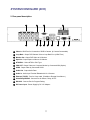
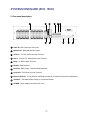
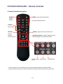
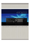
VT-E Series
4, 8, and 16 Channel Digital
Video Recorders
VITEK
• 4, 8, or 16 Video Inputs
• Remote Viewing over the Internet or LAN
• Supports both Dynamic and Static IP Addresses
• Up to 120 IPS Recording
• MPEG-4 Compression
• 4 Audio Inputs / 1 Audio Output
• 4, 8, or 16 Channel Alarm Inputs
• Control locally via Front Panel, USB Mouse or with the Included IR Remote Control
• PTZ Control over RS-485
• Built-In Bandwidth Throttling
CYAN
MAGENTA
YELLOW
BLACK
Before Installation ---------------------------------------------------------- 5
Main Features ------------------------------------------------------------- 6
System Organization -------------------------------------------------------- 8
System Contents ----------------------------------------------------------- 9
System Configure --------------------------------------------------------- 10
Front panel description -------------------------------------------------- 10
Rear panel description -------------------------------------------------- 11
Remote Controller description --------------------------------------------- 13
Connect & Power On ------------------------------------------------------- 14
Live display configure ------------------------------------------------------- 15
Split screen ---------------------------------------------------------- 15
Live display edit mode -------------------------------------------------- 16
Digital zoom ---------------------------------------------------------- 17
Sequence ------------------------------------------------------------ 18
Key Lock Function ----------------------------------------------------- 18
PTZ Camera control ---------------------------------------------------- 19
GENERAL ---------------------------------------------------------------- 20
DISPLAY ------------------------------------------------------------- 21
OSD ----------------------------------------------------------- 21
Monitor --------------------------------------------------------- 22
Sequence
------------------------------------------------------- 23
CAMERA ------------------------------------------------------------- 28
Camera Title ------------------------------------------------------ 29
Color Setup ------------------------------------------------------ 29
PTZ Setup ------------------------------------------------------- 30
Motion Sensor ---------------------------------------------------- 31
SOUND -------------------------------------------------------------- 34
Audio ----------------------------------------------------------- 35
Buzzer ---------------------------------------------------------- 35
2
SYSTEM ------------------------------------------------------------- 36
Date /Time ------------------------------------------------------- 36
Network ---------------------------------------------------------- 37
Mail ------------------------------------------------------------- 38
User Management -------------------------------------------------- 38
System Management ------------------------------------------------ 41
EVENT / SENSOR ------------------------------------------------------ 42
HDD Event -------------------------------------------------------- 42
Alarm Input ------------------------------------------------------- 43
Alarm Out -------------------------------------------------------- 43
Buzzer Out ------------------------------------------------------- 45
E-mail Notification -------------------------------------------------- 46
DISK MANAGEMENT ---------------------------------------------------- 47
RECORD ----------------------------------------------------------------- 48
Recording Operation ---------------------------------------------------- 48
Record Schedule Setup
------------------------------------------------49
Alarm Record Setup ---------------------------------------------------- 55
BACKUP ----------------------------------------------------------------- 56
SEARCH ----------------------------------------------------------------- 59
Search -------------------------------------------------------------- 59
Event Search --------------------------------------------------------- 62
Remote Client Setup -------------------------------------------------------- 64
Client software installation ------------------------------------------------ 64
Client software organization ---------------------------------------------- 66
Explanation of Function keys ------------------------------------- 67
Create a connect group ------------------------------------------------- 68
Detail Setup ---------------------------------------------------------- 69
Additional Configuration ------------------------------------------------- 71
3
Remote Search ------------------------------------------------------------ 72
Explanation of function keys ------------------------------------------ 73
Quick Search --------------------------------------------------------- 74
Archiving --------------------------------------------------------- 75
Still Shot -------------------------------------------------------- 75
Log Viewer ------------------------------------------------------- 76
Backup Player ----------------------------------------------------- 76
Print ------------------------------------------------------------ 77
Event Viewer ------------------------------------------------------ 77
Remote Recording Setup ------------------------------------------------- 78
Record ---------------------------------------------------------- 78
Camera ---------------------------------------------------------- 79
Sound ----------------------------------------------------------- 79
Event / Sensor ----------------------------------------------------- 80
System ---------------------------------------------------------- 81
4
BEFORE INSTALLATION
●
Installation should be carried out only by qualified personnel and in accordance with any electrical
regulations in force at the time
● The
DVR must be placed on a stable surface or mounted in an approved cabinet.
Adequate ventilation must be provided, taking particular care not to block any of the air vents on the DVR.
● Adequate protection against lightning strikes and power surges must be installed to prevent damage
to the DVR.
● Any safety warnings on the DVR and in these instructions must be adhered to.
● If cleaning is necessary, shutdown the DVR and disconnect power first. Use a soft dry cloth only… never
use any abrasive cleaners.
● Do not attempt to service or repair the DVR as opening or removing covers may expose dangerous
voltages or other hazards. Refer all servicing to qualified service personnel.
5
MAIN FEATURES
MOUSE CONTROL
Designed to be controlled by mouse and easy to use.
ENHANCED GRAPHICAL USER INTERFACE [GUI]
The DVR menu structure and on screen display is presented in a simple to use and logical GUI format.
GENUINE TRIPLEX OPERATION
The DVR will continue to record at full frame rate during local playback, local setup, multi user remote
viewing and playback and remote setup.
AUDIO
2 audio inputs(8,16CH, in case of 4CH, 4 audio inputs) are supported which can be assigned to any video
channel. Live and recorded audio can be monitored remotely over the internet and remote ‘talkback’ audio
transmission to the DVR is also possible.
BACKUP
Recorded footage (including audio) can be archived to USB memory stick.
Playback software is embedded with the backup files and the backup also contains the system event log
and backup log for full traceability.
REMOTE CONNECTION
Software is provided to allow remote connection to up to 4 DVRs in one session. Depending on user level,
Full DVR control is available over the internet as well as the ability to remotely configure the DVR.
Alarm outputs on the DVR can be remotely triggered over the internet.
COMPREHENSIVE RECORDING SETUP
Recording can be scheduled, alarm activated or motion activated. For each type of recording, frame rates,
image quality and audio recording properties can be adjusted per hour, per day and for each individual
channel.
The DVR also has a panic recording feature (from the front panel or external input) which overrides all
other recording settings to provide the best quality recording in the event of an emergency.
6
MAIN FEATURES
PTZ CONTROL
Full telemetry control is available from the front panel or remote connection and a wide number of speed
Dome protocols are supported. Protocols can be set individually for each channel and telemetry speed
can be adjusted to suit particular speed domes.
EXTENSIVE MONITOR SUPPORT
The DVR has 2 main monitor outputs (Composite, VGA) which can be used simultaneously.
Support is also provided for 1 spot monitor and spot monitor output can be programmed in the DVR setup.
LIVE DISPLAY
The DVR displays single or multi screen images and also has several sequence modes.
(standard and user definable)
CONFIGURATION BACKUP
All configuration settings on the DVR can be saved to USB memory stick or a PC file remotely.
The saved data can then be uploaded to other DVR units allowing rapid deployment where more than
one DVR is being installed.
EMAIL SUPPORT
The DVR can send emails to specific users to notify events such as alarm, motion detection,
hard drive failure etc.
7
SYSTEM ORGANIZATION
Alarm Sensor
Camera
Alarm out, Relay Out
Remote Client PC
Image Printer
Alarm Input/Out
NETWORK
AVI Backup
TCP/IP
Video In
WEB Client
Video Out
Backup
Remote
Controller
USB
VCR
VGA
Monitor
AV Monitor
8
SYSTEM CONTENTS
① Basic Contents
Power Cable
User’s Manual
Remote Controller
9
Remote Client
Program Install CD
AAA Battery X 2
SYSTEM CONFIGURE (4CH, 8CH, 16CH)
1. Front panel description.
1
2
3
4
8
5
9
6
10
7
12
1
Remote Controller Sensor : Communicate with the remote controller.
2
POWER : System Power On/Off
3
SCR MODE : Select split screen.
4
SEARCH : Enter playback mode.
5
MENU : Setup DVR all setting.
6
FAST REWIND : In Search mode, control fast rewind speed.
7
FAST FORWARD : In Search mode, control fast forward speed.
8
USB Port : For Mouse control and extra USB backup device.
9
LCD DISPLAY : Show Power, Recording, Network and Alarm status.
10
RETURN : Go back to the previous menu.
11
ENTER : Go selected menu.
12
CURSOR KEYS :
Move to RIGHT side. Play button in search mode.
Move to LEFT side. Back Play button in search mode.
Move to UP side.
Move to DOWN side.
10
11
SYSTEM CONFIGURE (4CH)
2. Rear panel description.
1
3
2
4
6
5
11
7
8
9
10
12
1
Video In : BNC Port for Connection of DVR & Camera. (4 Camera Connectable)
2
Loop Back : Output DVR Camera Video to Loop Back Port. (4 BNC Port)
3
Monitor Out : Output DVR Video to AV Monitor.
4
Spot Out : Output Spot-out Video to AV Monitor.
5
NTSC/PAL : Select NTSC or PAL Type.
6
VGA OUT : Output Video to a Computer Monitor by Connected VGA (Option)
7
SVHS : Output Video by Connected SVHS.
8
Audio Out : Output Audio Data.
9
Audio In : Audio Input Terminal Related with #1~4 Camera.
10
Ethernet (TCP/IP) : Port for Cross cable. (Possible to Remote Surveillance.)
11
Alarm/Relay/RS-485 : Connect Port for Sensor, Relay, & PTZ.
12
RS-232C : Connect Port for Program Debug.
13
DC Power Input : Power Supply by DC 12V Adaptor.
11
13
SYSTEM CONFIGURE (8CH, 16CH)
2. Rear panel description.
1
2
3
7
8
4
5
6
9
10
11
1
Video IN : BNC Video Input Port (8/16).
2
Monitor out : BNC Main Monitor Output.
3
Audio In : 2 x RCA Audio Line Input Terminal.
4
Alarm : 4 x Input TTL Alarm/Sensor Input Terminal.
5
Relay : 2 x Relay Output Terminal.
6
RS-485 : Serial Interface.
7
Spot Out : BNC Output – Sequenced Spot Monitors.
8
Audio Out : RCA Audio Line Out Terminal.
9
Ethernet (TCP/IP) : 10/ 100 Ethernet LAN/WAN connection (for Remote Access and configuration).
10 VGA OUT : VGA Main Monitor Output (to a computer Monitor).
11 POWER : Power adaptor connection (DC-12V).
12
SYSTEM CONFIGURE – Remote Controller
3. Remote Controller description.
POWER
MENU : Open System Setup Menu
System
ON/OFF
Channel Selection Buttons
ID Button
Select DVR ID
ID
RETURN
ENTER : Apply / Select /Go to Next Screen
Cancel /
Deselect
Previous Screen
Navigation Buttons : Used for Playback Control,
Menu Navigation, and PTZ/Focus Control
Change Display Search Menu
Mode
PTZ/IRIS Mode
• There are buttons on the controller that are unused, and their descriptions have been omitted.
• Remote Controller will only work when used within line-of-sight of the IR remote sensor on the DVR.
13
CONNECT & POWER ON
• Connect up to 4/8/16 CAMERA INPUTS as necessary.
• Connect one or more monitors to the DVR using the COMPOSITE, VGA connections
• Connect power to the DVR. The DVR checks for proper power connection and emits two beeps.
Press the POWER BUTTON on the front panel of the DVR to begin operation.
The DVR startup screen detects and checks the status
of hard drives. If this is your first time booting up, it
may ask you to format your drive, please select yes
and do so.
After startup diagnostics are complete, the operator must
logon to the system. The default user name is ‘ADMIN’.
Using the Remote Controller , input the default password
of ‘1234’ and press the ENTER button.
Double click on the Password tab then the Virtual
Keyboard will be displayed. Then click the password and
click the
button.
The DVR begins normal operation and shows the
default display of all 4/8/16 channels.
The status bar at the bottom of the screen shows
current time and date and percentage of hard drive used.
A title for each channel is shown
The red square and letter ‘T’ in the top right of each
channel display shows that the channel is recording in
Timer / Schedule mode.
14
LIVE DISPLAY
SPLIT SCREEN
Click the right mouse button on the Live Display
screen and Click the SCR MODE menu.
8 different display modes are supported by the 16 channel DVR.
By repeatedly pressing the SCR MODE button, the operator can choose between single screen,
4 screen, 6 screen, 8 screen, 9 screen, 13 screen, 16 screen and basic sequence modes.
Click the right mouse button on the Live Display
screen and Click the SEQUENCE menu.
All the display modes are static with the exception of the sequence mode. In this mode, the sequence
symbol (
) is displayed and each channel is shown in full screen for a set period of time (default 3 sec)
before switching to the next channel.
The sequence runs indefinitely until a different display mode is chosen.
15
LIVE DISPLAY
LIVE display edit mode
For each multi screen view mode, the operator can decide which channels to view and in what position.
Use the SCR MODE button to choose the multi screen mode to edit and then press ENTER to select LIVE
DISPLAY EDIT MODE.
In this example, the default 4 screen mode displays channels 1-4. To display channel 8 instead of
channel 2:
Using the Remote Controller, press number 2 – channel 2 changes to a blue screen.
16
LIVE DISPLAY
Digital Zoom
Click the right mouse button on the Live Display
screen and Click the ZOOM menu.
When viewing a channel in full screen, the operator can zoom in to a particular area by up to 8 times.
To use digital zoom, select the required channel and press the ZOOM button. The small window at bottom
right shows the full image and the main display area shows the zoomed portion.
Click the following button.
RETURN
To adjust the zoom level, select the ▶▶button to increase zoom or ◀◀ button to decrease zoom on the
screen by the remote controller
To move the zoom area around the image, select the ▶ or ◀ button to adjust the position of the zoom
square.
Press the RETURN button to return to normal live display mode.
17
LIVE DISPLAY
Sequence
Click the right mouse button on the Live Display
screen and Click the SEQUENCE menu.
Press the SEQ button. Each channel is shown in full screen for a set period of time (default 3 sec)
before switching to the next channel.
To stop the sequence on a particular channel, press the SEQ button again.
More complex sequences can be programmed through the setup menu (page 23)
Key Lock Function
Click the right mouse button on the Live Display
screen and Click the KEY LOCK menu.
Double click on the Password tab
then the Virtual Keyboard will be
displayed. Then click the password
and click the
button.
An operator with ADMIN rights can choose to lock the DVR front panel to prevent any un authorized control.
Press the F1 button, enter the default password ‘1234’
And press ENTER. All buttons are now disabled.
To unlock, press the F1 button again and enter the default password ‘1234’
18
LIVE DISPLAY
PTZ Camera Control
Click the right mouse button on the Live Display
screen and Click the PTZ menu.
Speed domes and other telemetry devices connected to the DVR, can be fully controlled.
In live display mode, press the PTZ button. To select a camera to control, use the CHANNEL SELECTION
buttons.
Pan and tilt movement is controlled by the CURSOR KEYS, zoom is controlled by pressing the ◀◀ & ▶▶
If you enter the PTZ button again, it will be changed to the Preset mode.
Press SCR MODE or SEQUENCE buttons to decrease or increase the preset number.
Press PAUSE to program the preset, or ENTER to call an existing preset.
Press RETURN to exit PTZ mode and return to live view.
19
GENERAL
Click the right mouse button on the Live Display
screen and Click the SETUP menu.
Double click on the Password
tab then the Virtual Keyboard will
be displayed. Then click the
password and click the
button.
Press the MENU button to bring up the menu login screen.
Only operators with ADMIN rights can configure the DVR. Enter the default password of ‘1234’
Click the GENERAL menu.
To navigate around any items in the setup menu, use the CURSOR KEYS and the ENTER and RETURN
buttons. In general, the ENTER button is used to select and change a particular item and the RETURN
button is used to cancel a change or exit from a particular setup screen.
To setup all main system functions, highlight SYSTEM SETUP and press ENTER.
20
GENERAL
DISPLAY
: To setup the various display options, highlight DISPLAY and press ENTER
DISPLAY - OSD
Click the OSD menu and click the ON/OFF menu.
Then click the
button for ON/OFF.
STATUS BAR : Turns the status bar at the bottom of the live display ON or OFF
CAMERA TITLE : Determines whether the camera title is displayed
EVENT ICON : Determines whether the DVR recording status is shown at the top right of each channel
display window
BORDER : Determines whether there is a border around each channel in multi screen display mode
BORDER COLOUR : If the border is ON, the operator can choose the color
ALPHA BLENDING : Changes the transparency of the menu window.
To change any of these settings, highlight OSD and press ENTER to select. Use the CURSOR KEYS to
navigate to the option required. Press ENTER to select the option (the cursor changes to orange) and use
the CURSOR KEYS to change the setting. Press ENTER to save the setting or RETURN to cancel.
21
GENERAL
DISPLAY : MONITOR
Click the MONITOR menu and click the ON/OFF
button.
Then click the
button for ON/OFF.
SEQUENCE DWELL : The time that each screen is displayed in a sequence operation.
SPOT-OUT DWELL : The time that each screen is displayed on the spot monitor outputs.
DE-INTERLACE MODE : When recording any channels in D1 resolution (704 x 576) this should be set to
ON to prevent judder during playback.
ALARM POP-UP MODE : When set to ON, an alarm input will cause the associated channel to display
full screen.
ALARM POP-UP DWELL : Determines how long the full screen popup is displayed after an alarm input.
If the alarm condition continues, the popup screen is displayed constantly.
MOTION POP-UP MODE : When set to ON, motion detection will cause the associated channel to display
full screen
MOTION POP-UP DWELL : Determines how long the full screen popup is displayed after motion detection.
If motion continues, the popup screen is displayed constantly
To change any of these settings, highlight MONITOR and press ENTER to select.
Use the CURSOR KEYS to navigate to the option required. Press ENTER to select the option (the cursor
changes to orange) and use the CURSOR KEYS to change the setting. Press ENTER to save the setting
or RETURN to cancel.
Please note: When display modes are changed, the DVR must be shutdown and restarted for
changes to take effect
22
GENERAL
DISPLAY : SEQUENCE
Click the SEQUENCE menu.
When the SEQ button is pressed, the default sequence will cycle through all 16 channels, one by one.
Sequence setup allows the operator to define a custom sequence using mixed multi screen views and any
desired channels.
Click the ADD menu.
To add a new sequence, highlight ADD and press ENTER
Sequence title is highlighted – press ENTER to bring up the virtual keyboard and key in a name or
reference number for the new sequence.
23
GENERAL
DISPLAY : SEQUENCE continued
Double click on the SEQUENCE TITLE tab.
Virtual Keyboard will be displayed. Then click the
any name and click the
button.
Move around the virtual keyboard using the CURSOR KEYS and ENTER to select a character.
To delete a character, use ←. To change keyboard case and access symbols, use ↑.
To exit, press RETURN
Click on the ACTIVATION tab and click the
button for select ON/OFF.
Set ACTIVATION to ON and highlight SAVE.
Then press ENTER to display the sequence programming screen.
24
GENERAL
DISPLAY : SEQUENCE continued
Double click on the box and then the box color will
change to white.
When you click each time, the split screen changes.
The square on the top left of the display represents the first sequence screen that will be displayed.
To edit the screen, press ENTER to turn the cursor orange. Using the up and down CURSOR KEYS,
choose the screen type (single or various multi screen options).
Right mouse click on the selected split screen.
Then click the camera number that user wants.
When the correct screen type is displayed, use the CHANNEL SELECTION button to enter the channels
required for each portion of the multi screen.
Note: Only one instance of each channel can be displayed.
To remove a channel, press the appropriate CHANNEL SELECTION button again.
25
GENERAL
DISPLAY : SEQUENCE continued
When finished selecting the camera number, click
on the screen. Then next split screen appears.
Make the split screen and select the camera
number.
When all the channels have been completed, press ENTER to save the sequence screen and begin
creating the next one.
Up to 16 different sequence screens can be created.
To finish, right mouse click on the screen.
Click the SAVE & EXIT menu.
To finish editing the sequence, press RETURN and then ENTER to save & exit.
26
GENERAL
DISPLAY : SEQUENCE continued
When you click the SEQUENCE menu by right
mouse button, new saved split screen activate.
The new sequence is now saved and can be started by pressing the SEQUENCE button when in live view.
DISPLAY : SPOT-OUT
Click the SPOT-OUT menu and click the camera
channel for ON/OFF.
The DVR has 1 SPOT MONITOR OUTPUT. One displays a full screen sequence of
particular channels, depending on the settings configured in this menu.
For spot monitor, the operator can decide which channels are displayed.
27
GENERAL
DISPLAY : SPOT-OUT continued
Click the camera number that the user wants.
To change the behavior of the spot monitor outputs, use the CURSOR KEYS and ENTER button to move
around the channels and tick to include or un-tick to exclude from the spot out sequence.
When all changes have been made, highlight APPLY and press the ENTER button to save.
CAMERA
Click the CAMERA menu.
To setup the various camera options, highlight CAMERA and press the ENTER button.
28
GENERAL
CAMERA : CAMERA TITLE
Click the CAMERA TITLE menu and click the
ON/OFF button on the COVERT menu.
Then click the
button for ON/OFF.
Click the CAM No on the TITLE menu and
change the camera name.
COVERT: When set to ON, the camera image is not displayed in live display but continues to be recorded.
TITLE: For each camera, a title of up to 11 characters can be set using the virtual keyboard.
CAMERA : COLOR SETUP
Click the COLOR SETUP menu and click the
value on the BRIGHTNESS, CONTRAST, TINT
and COLOR menu.
Brightness, contrast, tint and color can be adjusted for each individual channel.
Highlight which channel to modify and press ENTER button.
29
GENERAL
CAMERA : COLOR SETUP continued
Click the each value by
button.
The selected channel is displayed in full screen.
BRIGHTNESS, CONTRAST, TINT and COLOUR can be changed as necessary.
To modify a different channel, highlight CAMERA and choose the desired channel.
Press RETURN when all changes are complete.
CAMERA : PTZ SETUP
Click the PTZ SETUP menu and click the each
value on the ADDRESS, PROTOCOL and
BAUD RATE menu.
Change the value by the
ADDRESS: The unique ID of the PTZ device.
PROTOCOL: The protocol of the PTZ device.
BAUD RATE: The baud rate of the PTZ device.
30
button.
GENERAL
CAMERA : PTZ SETUP continued
Click the
by the
button and change the detail value
button.
PTZ properties can also be adjusted for each channel by selecting the
icon and pressing ENTER.
Note that some settings, such as AUTO FOCUS, may not be compatible with particular PTZ equipment.
If this is the case, changing this value will have no effect on PTZ control
CAMERA : MOTION SENSOR
Click the MOTION SENSOR menu and click the
value on the SENSITIVITY menu.
Change the value by
button.
SENSITIVITY : Between 1 (Lowest) and 10 (Highest) and determines the degree of motion required
before recording is activated.
31
GENERAL
CAMERA : MOTION SENSOR continued
Click the
button.
AREA SETUP : Choosing this option allows the operator to define which areas of the image are monitored
for motion detection.
Light blue grid squares represent detection areas, grey grid squares are ignored.
The area on the right shows that motion will be detected across the entire image.
To quick select or deselect the entire grid, click the
right mouse button and click the SELECT ALL or
DESELECT ALL menu.
To quick select or deselect the entire grid, press RETURN to bring up the motion menu.
Highlight SELECT ALL or DESELECT ALL as appropriate and press ENTER.
32
GENERAL
CAMERA : MOTION SENSOR continued
Drag the grid by the left mouse button.
To select or deselect specific areas, press
ENTER to bring up the green cursor square
in the top left of the display.
Move the cursor using the CURSOR KEYS
to the first corner of the area to be set and
press ENTER – the cursor turns orange.
Use the CURSOR KEYS to increase the size
of the motion cursor as required.
Press ENTER to change from selected to
deselected (or vice versa). Repeat the above
sequence as necessary to mask off or include
other areas of the image.
33
GENERAL
CAMERA : MOTION SENSOR continued
After you drag the grid by the left mouse, click
the right mouse button.
Then click the SAVE & EXIT menu.
Once the detection area has been defined, press RETURN and choose SAVE & EXIT to save the area
and return to the motion setup menu.
Please note : a motion detection recording schedule must be defined in the RECORD MENU
described on page 49
SOUND
Click the SOUND menu.
To setup the various sound options, highlight SOUND and press ENTER
34
GENERAL
SOUND : AUDIO
Click the AUDIO menu and click the ON/OFF menu.
Then click the
button for ON/OFF.
LIVE AUDIO : When set to ON, the selected audio channel can be monitored on the AUDIO OUTPUT.
AUDIO MONITORING CHANNEL
: Specify which one of the 2 AUDIO INPUTS is routed to the AUDIO OUTPUT.
NETWORK AUDIO TX : When set to ON, live and playback audio is transmitted to a remote PC connection.
NETWORK AUDIO RX : When set to ON, allows a remote PC connection to send audio back to the DVR.
SOUND : BUZZER
Click the BUZZER menu and click the ON/OFF
menu.
Then click the
button for ON/OFF.
KEYPAD: When set to ON, each front panel button press is confirmed by a beep.
REMOTE CONTROL: When set to ON, each command received from the IR remote is confirmed by a
beep.
35
GENERAL
SYSTEM
Click the SYSTEM menu.
To setup the various system options, highlight SYSTEM and press ENTER.
DATE / TIME
Click the DATE / TIME menu and click the
ON/OFF button.
Then click the
button for ON/OFF.
DATE FORMAT : Determines how the date is displayed.
TIME FORMAT : Determines how the time is displayed.
NETWORK TIME SERVER SETUP
: If the DVR is connected to the Internet, the time and date can be accurately set by selecting SYNC and
pressing ENTER
TIME ZONE SETUP : should be set according to the region that the DVR is used in.
D.S.T. : When set to ON, the DVR will automatically adjust the time by one hour on the relevant date in
spring and autumn.
36
SYSTEM
SYSTEM : NETWORK
Click the NETWORK menu and click the
ON/OFF menu.
Then click the
button for ON/OFF.
DHCP : When enabled, the DVR will obtain an IP address automatically if connected to a DHCP server
or router.
DDNS : When enabled, the DVR can be accessed through a Dynamic DNS server.
Commonly used if a broadband connection does not have a static IP address.
WEB SERVICE : When enabled, allows remote connections using Internet Explorer or other web browsers.
IP ADDRESS : If DHCP is not being used, the IP address can be manually set.
GATEWAY : If DHCP is not being used, the gateway IP address can be manually set.
SUBNET MASK: If DHCP is not being used, the subnet mask can be manually set.
1ST DNS SERVER : If DHCP is not being used, the first DNS server can be manually set
2ND DNS SERVER : If DHCP is not being used, the second DNS server can be manually set
DDNS SERVER : If DDNS is enabled, the host DDNS server is specified here
NET CLIENT PORT : The port number that the DVR uses to support remote connection from the client
software
WEB SERVER PORT : The port number that the DVR uses to support remote connection from Internet
Explorer or other web browsers
NETWORK SPEED : Specifies the maximum bandwidth that the DVR can use during a remote connection.
Please note: If any network settings are modified, the DVR will need to be restarted for changes to take
effect
Please note: For further information on network settings and remote connections, please refer to page 53
37
SYSTEM
SYSTEM : MAIL
Click the MAIL menu and click the ON/OFF menu.
Then click the
button for ON/OFF.
SERVER : The SMTP outbound email server that should be used to send email notifications.
PORT : The outbound email port number.
SECURITY : Set to OFF if the SERVER does not require a username and password to connect.
USER : Enter a username to identify the DVR in email messages.
PASSWORD : If SECURITY is set to ON, enter the password here.
Please note : A USER must be entered for the mail function to operate correctly. The username
must not contain spaces.
SYSTEM : USER MANAGEMENT
Click the USER MANAGEMENT menu and
ADMIN on the GROUP menu.
By default, the DVR is configured with a user ID of ADMIN, belonging to the ADMIN group and with a
password of 1234.
As well as the ability to add new users, existing user details can be modified
To modify user details, highlight the user with the green cursor and press ENTER button.
38
SYSTEM
SYSTEM : USER MANAGEMENT continued
Double click the PASSWORD menu and ADMIN
on the GROUP menu.
Click the password and enter
button.
USER ID : Edit the user ID using the virtual keyboard.
PASSWORD : Change the password using the virtual keyboard.
NOTE: To delete the existing password use the ◀◀ key.
GROUP : Users can belong to one of three groups - ADMIN, MANAGER or USER.
E-MAIL : Enter the users email address if email notification is required.
E-MAIL NOTIFICATION : Enable or disable email notifications for this particular user.
Please note: For security reasons, it is recommended that the ADMIN user password is changed
as soon as possible
39
SYSTEM
SYSTEM : USER MANAGEMENT continued
Click the ADD menu Enter the USER ID and
PASSWORD by double click.
After you click the USER ID and PASSWORD,
click the button.
To add users, highlight ADD and press ENTER button.
The new user details can be added using the steps outlined above.
More Information about user management
Up to seven individual users can be created, and each user can belong to one of three user groups:
USER : Members of this group can only adjust live view settings. Playback and DVR setup is not
available.
MANAGER : Members of this group can adjust live view settings and playback recorded footage.
(including covert cameras)
ADMIN : Members of this group have full control over the DVR including setup.
Please note : Any user can be deleted except the default ADMIN user
40
SYSTEM
SYSTEM : SYSTEM MANAGEMENT
Click the SYSTEM MANAGEMENT menu.
And click the PRESS menu for FW Upgrade,
Factory Default and System Data.
S/W version : Shows the firmware version of the DVR.
H/W version : Shows the hardware version of the DVR.
VIDEO SIGNAL TYPE
: The DVR automatically switches between PAL and NTSC depending on the channel 1 input signal at
power on.
DISK CAPACITY
: The first value shows the amount of hard drive capacity used by recorded footage, the second value
shows the total hard drive capacity installed.
IP ADDRESS : Shows either the manual IP address entered in NETWORK setup or the IP address
assigned by a DHCP server if enabled
MAC ADDRESS : Shows the MAC (Media Access Control) address of the DVR. It is unique – no other
network device has this MAC address.
SYSTEM NAME : A system name of up to 10 characters can be defined. It is used so that notification
emails can be identified.
F/W UPDATE : Firmware updates may be released periodically to enhance system performance and
add extra features. The operator can upgrade the firmware using a USB memory stick.
FACTORY DEFAULT : If settings have been changed which cause erratic behavior, the factory default
settings can be loaded.
BACKUP DATA : System settings can be saved to a USB memory stick. The settings can be reloaded
in case of accidental factory reset or can be transferred to another DVR if multiple
units need to be installed with the same settings. All information is saved apart from
network settings and system name.
41
SYSTEM
EVENT / SENSOR
Click the EVENT / SENSOR menu.
To setup the various event handling options, highlight EVENT/SENSOR and press ENTER.
EVENT / SENSOR : HDD EVENT
Click the HDD EVENT menu and click the DRIVE,
SMART ALARM and CHECK INTERVAL value.
Then click the value by
The DVR can monitor the hard drives and detect problems that may be developing.
DRIVE : Selects which hard drive to configure for monitoring.
SMART ALARM : Enables SMART disk monitoring.
CHECK INTERVAL : Can be adjusted as desired.
42
button to change .
SYSTEM
EVENT / SENSOR : ALARM INPUT
Click the ALARM INPUT menu and click the
OPERATION and TYPE value.
Then click the value by
button to change.
Determines the behavior of each of the 4 alarm inputs.
OPERATION : Alarm inputs can be enabled or disabled.
TYPE : Alarm inputs can be set as normally open or normally closed.
EVENT / SENSOR : ALARM OUTPUT
Click the ALARM OUTPUT menu and click the
each value.
Then click the value by the
Determines the behavior and actions that will trigger each of the 1 alarm outputs.
Behavior settings
CHANNEL : Choose which alarm output to configure.
OPERATION : The selected alarm output can be enabled or disabled.
43
button to change.
SYSTEM
EVENT / SENSOR : ALARM OUTPUT continued
MODE : Can be either TRANSPARENT (the output is active only when the trigger criteria is present) or
LATCHED (the output is active for a set period of time after a trigger).
DURATION : In LATCHED mode, the time that the alarm output remains active after it has been triggered.
TYPE : Can be set to high (0V to +5V when activated) or low (+5V to 0V when activated)
HDD EVENT : Determines whether a hard drive event triggers the alarm output
Action settings
ALARM : Determines whether alarm inputs will trigger the alarm output
VIDEO LOSS : Determines whether video loss on any of the selected channels will trigger the alarm output
MOTION : Determines whether motion detection on any of the selected channels will trigger the alarm output
Remember to select APPLY and press ENTER to save all settings before exiting these menus
44
SYSTEM
EVENT / SENSOR : BUZZER OUT
Click the BUZZER OUTPUT menu and click the
each value.
Then click the value by the
button to change.
Determines the behavior and actions that will trigger the internal buzzer.
Behavior settings
OPERATION : The internal buzzer can be enabled or disabled.
MODE : Can be either TRANSPARENT (the buzzer sounds only when the trigger criteria is present)
or LATCHED (the buzzer sounds for a set period of time after the trigger).
DURATION : In LATCHED mode, the time that the buzzer sounds after it has been triggered.
HDD EVENT : Determines whether a hard drive event sounds the buzzer.
Action settings
ALARM : Determines whether alarm inputs will sound the buzzer.
VIDEO LOSS : Determines whether video loss on any of the selected channels will sound the buzzer.
MOTION : Determines whether motion detection on any of the selected channels will sound the buzzer.
Remember to select APPLY and press ENTER to save all settings before exiting these menus.
Email settings must also be configured in MAIL and USER MANAGEMENT settings described
on page 39
45
SYSTEM
EVENT / SENSOR : EMAIL NOTIFICATION
Click the EMAIL NOTIFICATION menu and click
each value.
Then check the usage by the left mouse click.
Determines the behavior and actions that will send an email to a remote user.
Behavior settings
NOTIFICATION : Email notification can be turned ON or OFF.
HDD EVENT : Determines whether a hard drive event sends an email.
Action settings
ALARM : Determines whether alarm inputs will send an email.
VIDEO LOSS : Determines whether video loss on any of the selected channels will send an email.
MOTION : Determines whether motion detection on any of the selected channels will send an email.
Email settings must also be configured in MAIL and USER MANAGEMENT settings described
on page 39
46
SYSTEM
DISK MANAGEMENT
To setup the various event handling options,
highlight EVENT/SENSOR and press ENTER.
Click the EVENT / SENSOR menu.
Click the DISK MANAGE menu and click the each
value.
Then click the ON/OFF value by the
button.
And click the START menu for the Format.
To manage the internal hard drives, highlight DISK MANAGE and press ENTER.
RECORD TIME LIMIT : In certain circumstances, it may be necessary to limit the amount of footage stored.
on the DVR (to comply with data protection laws for example).
Recording can be limited to 12 hours, 1 day, 2 days, 3 days, 1 week or one month. Once the DVR has
this amount of footage stored, it will start to overwrite the earliest recorded footage.
OVERWRITE : When set ON, the DVR will start overwriting the earliest recorded footage once the hard
drive becomes full. In this case, the percentage of hard drive used shown in live display will
always be 99%. When set to OFF, the DVR will stop recording when the disk becomes full.
FORMAT : If necessary, all footage can be erased from the DVR using this option
Please note: When RECORD TIME LIMIT is set, the percentage of HDD used shown in live
display mode may never reach 99%.
For example, if the total HDD capacity of the DVR allows for a recording time of
4 days under normal operation, if the RECORD TIME LIMIT is set to 2 days, the
percentage of HDD used will never exceed 50%.
Please note: When a RECORD TIME LIMIT is set, the OVERWRITE option cannot be changed.
47
RECORD
RECORD
Click the RECORD menu.
To setup the recording behavior of the DVR, highlight RECORD MENU and press ENTER button.
RECORDING OPERATION
Click the RECORDING OPERATION menu and
click the each value.
Then click the value by the
button to change.
SCHEDULE MODE : Either DAILY (one schedule will apply to every day of the week)
or WEEKLY (each day of the week has its own schedule).
PRE EVENT RECORDING TIME
: When the DVR is not in continuous recording mode, this setting determines the amount of footage that
is always recorded before an event occurs. (motion detection, alarm input etc.)
POST EVENT RECORDING TIME
: When the DVR is not in continuous recording mode, this setting determines the amount of footage that
is always recorded after an event occurs. (motion detection, alarm input etc.)
48
RECORD
TIMER / MOTION SETUP
Click the TIMERMOTION SETUP menu.
This setup screen allows the operator to configure scheduled and motion detection recording.
There are 2 sections:
PARAMETER : Recording settings for each channel can be defined across a 24 hour period,
in blocks (for example between 09:00 and 18:00) or for each individual hour.
Note that when SCHEDULE MODE is set to WEEKLY, each day of the week can also be
selected.
SCHEDULE : This section determines at what times the DVR will record and whether it is continuous
recording or motion detection.
PARAMETER
To change PARAMETER settings, highlight MOTION RECORD SCHEDULE and press ENTER.
The 24 hour time bar is highlighted in yellow.
49
RECORD
PARAMETER continued
Click the TIMEBAR that user wants.
Press ENTER to display the green cursor.
The green cursor shown represents one hour (in this case between 00:00 and 01:00).
The table below the time bar shows the recording settings for this time period.
Drag the time that user wants.
Example: To change the recording settings between 09:00 and 18:00.
Use the CURSOR KEYS to move the green cursor to the 09:00 position and press ENTER.
The cursor changes to white to show the start position.
Use the CURSOR KEYS to stretch the white cursor across to the 12:00 position.
50
RECORD
PARAMETER continued
Click the SIZE, FPS, QUALITY and AUDIO value.
Then click the value by
button to change.
Press ENTER. Recording settings for the selected time period are displayed.
SIZE : Recording resolutions of 352x288, 704x288 or 704x576 can be selected for each channel.
FPS : Frame rates between 1 and 25 can be set for each channel.
QUALITY : Four different picture recording qualities can be set for each channel.
AUDIO : If audio devices are connected to the DVR, any audio channel can be assigned to any of the
video channels.
During playback, when a particular channel is selected in full screen, the assigned audio channel will
be played back at the same time.
Adjust values as desired, and select OK to finish and return to the parameter menu. Other time periods
can be configured in the same manner.
Remember that if SCHEDULE MODE is set to WEEKLY, recording settings need to be changed for
each day as well as for each particular time.
The default settings for all channels is 352 x 288, 7FPS, HIGHEST quality.
Note: The DVR supports a maximum recording rate across all channels of 112 frames per second
at 352x288 resolution. As settings are adjusted, the ‘frames available’ at bottom left displays
the number of available frames still remaining and must always be zero or higher.
If, whilst changing recording settings, this figure becomes negative, recording resolutions
and / or frame rates must be lowered to increase the ‘frames available’ value to zero or above.
51
RECORD
SCHEDULE
Click the SCHEDULE.
To change SCHEDULE settings, highlight MOTION RECORD SCHEDULE and press ENTER.
The schedule box is highlighted in yellow.
Click the Time and Channel.
Press ENTER to display the green cursor.
Example : To set all channels to motion detection recording only between 13:00 and 00:00.
Use the CURSOR KEYS to move the green cursor to the 13:00 position and press ENTER.
The cursor changes to white to show the start position.
52
RECORD
SCHEDULE continued
Drag the Time and Channel by left mouse
button.
Use the CURSOR KEYS to stretch the white cursor across and down to select all channels
between your desired times.
After drag, click the Motion button.
Press ENTER, highlight MOTION and press ENTER again.
53
RECORD
SCHEDULE continued
The selected area now displays the symbol for motion recording (marked blue block).
Repeat the above procedure to set different recording schedules for individual channels and time periods.
The schedule screen has 3 symbols to show the different recording modes.
Dark blocks: No scheduled or motion recording.
Light blue blocks: The DVR will record continuously.
Marked blue block: The DVR will only record when motion is detected.
54
RECORD
ALARM RECORD SETUP
Click the ALARM SETUP menu.
The setting is same as record setup.
This setup screen allows the operator to configure alarm input activated recording.
PARAMETER : Recording settings for each channel can be defined across a 24 hour period,
in blocks (for example between 09:00 and 18:00) or for each individual hour.
Note that when SCHEDULE MODE is set to WEEKLY, each day of the week can also be
selected.
SCHEDULE : This section determines at what times the DVR will monitor the alarm inputs and activate
recording.
Please refer to Timer / motion setup on page 49 for details on setting up PARAMETER
and SCHEDULE.
Alarm activated recording can be used in conjunction with timer / motion
recording. For example, the DVR could be configured to record
continuously at a low frame rate (set in timer / motion setup) and then
increase to a higher frame rate during an alarm input (set in alarm setup)
55
BACKUP
BACKUP
Click the BACKUP menu.
To backup, highlight EVENT/SENSOR and press ENTER.
OR
Click the right mouse button on the Live Display
screen and Click the ARCHIVING menu.
Double click on the Password
tab then the Virtual Keyboard will
be displayed. Then click the
password and click the
button.
To archive recorded footage to USB memory stick or CD, press the F2 button.
To protect unauthorized viewing and distribution of footage, only the ADMIN user level can archive footage.
To login as ADMIN, enter the default password of 1234 and press ENTER.
56
BACKUP
BACKUP continued
Click the each value.
Then click the value by
button to change.
Click the START menu.
The Archiving screen allows the operator to choose exactly what to backup and to where.
Use the CURSOR KEYS to navigate around the Archiving screen. To change any value or setting:
Press ENTER to change the green cursor to orange.
Use the up and down CURSOR KEYS to change the value.
Press ENTER to accept the value or RETURN to cancel.
To change a tick box setting, press ENTER to toggle on or off.
SELECT DEVICE: Choose between CDR or USB.
FROM / TO: Start and end time to backup.
MODE: ‘Writing or ‘Erase and Write’
A/V CHANNEL: Video and audio for any channel can be included or excluded from the backup.
TITLE: The name of the archive set.
EVENT: When selected, the event log for the particular archive time period is included.
Please note: If using a USB memory stick, it must be inserted before selecting the archiving menu
57
BACKUP
BACKUP continued
Once all the desired archive options have been
selected, highlight the START button and press
ENTER.
The DVR displays a list showing the exact
information to be archived and the total archive
size.
If the ORIGINAL SIZE is larger than the available
space on the backup media, the END TIME of
the archive set is reduced accordingly.
The MODIFIED SIZE is the final file size of the
archive set.
Select OK and press ENTER to begin the
archive process.
The footage is extracted to a temporary area on
the hard drive.
Once extracted, the footage is copied to CD
or USB.
Note that depending on the amount of footage
selected for archive, the extracting and burning
process may take some time, during which the
DVR cannot be used.
Normal recording is unaffected by the archive
process.
58
SEARCH
SEARCH
Click the right mouse button on the Live Display
screen and Click the SEARCH menu.
Double click on the Password
tab then the Virtual Keyboard will
be displayed. Then click the
password and click the
button.
To search for a particular section of recorded footage, press the SEARCH button.
To protect unauthorized viewing of footage, only ADMIN and MANAGER user levels can playback footage.
To login as ADMIN, enter the default password of 1234 and press ENTER.
Click the date that the user wants.
The DVR uses a calendar and timeline search method for quick access to recorded footage.
The calendar displayed on the left shows the current month.
Days highlighted in green have recorded footage.
The timeline on the right shows a 24 hour status of all channels for the selected day. Light blue areas show
recorded footage.
To select the date, press ENTER button.
59
SEARCH
SEARCH continued
Drag the time bar by left mouse button.
Press RETURN to change the calendar and use the CURSOR KEYS to move the square to the required
day.
MEMORY : To change the date, every time have to press RETURN button. .
As different days are selected, the timeline display also changes to show recorded footage on that day.
Press RETURN to choose the day.
Click the PLAY menu.
Use the CURSOR KEYS to move the timeline cursor left or right to select the time segment required.
Each movement of the timeline cursor increases or decreases the time by 15 minutes.
The currently selected time is displayed above the calendar.
Press ENTER to begin playback from the selected time.
60
SEARCH
SEARCH continued
The default playback mode is 4/8/16 screen
display.
By pressing DISPLAY or using the CHANNEL
SELECTION buttons, it is possible to display
single screen or other multi screen formats in
a similar way to the live display mode.
During playback, pressing the ▶▶ button
increases the playback speed by up to 64
times. (2x, 4x, 8x, 16x, 32x, 64)
Pressing ◀◀ button, anticlockwise will
reverse play by up to 64 times when playback
is paused.
To exit playback mode and return to the
search screen to choose another time and
date, press RETURN.
To exit the search screen and go back to live
view, repeatedly press RETURN.
61
SEARCH
EVENT SEARCH
Click the right mouse button on the Live Display
screen and Click the SEARCH menu.
Double click on the Password
tab then the Virtual Keyboard will
be displayed. Then click the
password and click the
button.
The DVR event log stores events such as motion and alarm activated recording, video loss etc.
To search for an event and playback the recorded footage, press the SEARCH button and log in as
ADMIN with the default password of 1234.
Click the SEARCH BY EVENT menu and each
value.
Then click the value using the
button to
change.
Click the START menu.
To display the event log screen, press the right
CURSOR KEY to select SEARCH BY EVENT and press ENTER.
Various filters can be used to limit the number of events displayed. Using the CURSOR KEYS and ENTER
button, select the FROM and TO date / time and the events and channels required.
62
SEARCH
EVENT SEARCH continued
Click the START menu.
Highlight START and press ENTER to display the event log for the criteria selected.
To playback footage for a particular event, select the event from the list using the CURSOR KEYS and
press ENTER.
Playback resumes from the moment the selected event occurred and continues until stopped by the operator.
During event search playback, the ▶▶ & ◀◀ button and playback buttons can be used as normal.
To stop playback and return to live view mode, repeatedly press RETURN.
Note: The event log search contains the following selectable entries:
ALARM: When ticked, all alarm input events are displayed for the chosen date range.
TIMER: When ticked, scheduled recording operations are displayed for the chosen date range.
MOTION: When ticked, all motion detection events are displayed for the chosen date range.
ETC: When ticked, all other events (Video loss, remote connection etc.) are displayed for the
chosen date range.
63
REMOTE CLIENT SETUP
The DVR is supplied with software to allow remote connections either on a direct LAN connection
or over the Internet.
The remote client allows full live viewing of the DVR including control of PTZ cameras.
In addition, playback, remote setup, audio talkback, local backup and remote alarm triggering can
all be achieved.
Client Software Installation
Insert the CD supplied with the DVR into your
PC’s CD-ROM drive. The install process will begin
automatically and display the following screen.
Click ‘Next>’ to continue.
Click ‘Next>’ to begin installation.
64
REMOTE CLIENT SETUP
The DVR remote client software is installed.
A final install screen is displayed confirming that
installation is successful.
Two icons are created on the PC desktop.
‘Remote Agent’ is the main software package.
‘BackupPlayer’ is the software to view archive
footage from the DVR.
To begin using the remote client software, double
click the icon on the desktop or click:
Start – Programs –RemoteAgent – DVR –
RemoteAgent.
The main remote client window is displayed.
65
REMOTE CLIENT SETUP
Client Software Organization
④
⑤
⑥
⑦
⑧
⑨
⑩
①
①
②
③
⑥
CHANNEL SELECTION buttons
②
STATUS button
③
ALARM button
CONNECT button
DISCONNECT button
⑦
TALKBACK button
⑧
DISPLAY button to choose
1,4,9 or 16 screen display
SEQUENCE button
AUDIO button
④
MANUAL SWITCH button
SEARCH button to access remote playback
FULL SCREEN button
SETUP button to configure DVR connections
⑨
DVR SETUP button to adjust DVR settings remotely
SAVE TO AVI button
EVENT VIEWER button
⑤
⑩
DROP DOWN LIST to select a DVR connection
66
PTZ CONTROL button
REMOTE CLIENT SETUP
EXPLAINATION OF FUNCTION KEYS
① CAMERA SELECTION Button : Indicate Connected Camera No. & Select camera No to see the image.
② STATUS Button : Show the connected DVR.
③ ALARM Button : Control Alarm output.
TALKBACK Button : Communicate between DVR and Remote Client.
AUDIO Button : Listen live audio (ON/OFF).
④ SEARCH Button : Entering the Search mode to playback the image.
SETUP Button : Entering the client software to change or check the setting.
DVR SETUP Button : Entering the connected DVR to change or check the setting.
⑤ DROP DOWN LIST : Select the group to connect.
⑥ CONNECT Button : Connect DVR.
DISCONNECT Button : Disconnect DVR.
⑦
DISPLAY Button : Change the division screen to 1,4,9 or 16.
⑧
SEQUENCE Button : Change the live screen automatically.
MANUAL SWITCH Button : Change the live screen manually by mouse click.
FULL SCREEN Button : Change to the full screen.
⑨
SAVE TO AVI Button : Save the current displayed image to AVI file.
EVENT VIEWER Button : Show the current event in DVR and find image.
⑩
PTZ CONTROL Button : Control PAN/TILT/ZOOM of camera.
67
REMOTE CLIENT SETUP
CREATE A CONNECT GROUP
The DVR remote client software can be
configured with any number of connection
groups.
Each connection group can consist of up to
4 DVRs.
To create a connection group, click the SETUP
button to display the Local configuration screen.
In the ‘Group’ window on the left,
right click ‘Site’ and choose ‘Add Group’.
Enter a name to easily identify the connection
group and click OK.
The new group is created.
68
REMOTE CLIENT SETUP
DETAIL SETUP
Details for up to 4 DVRs can be added to the ‘OFFICE’
group. Click ‘OFFICE’ to highlight it and then enter the
following information in the ‘DVR Information’ window.
Name: Any name that will easily identify the DVR.
IP / Domain Name: The IP or DDNS address of
the DVR.
Port: The network port of the DVR.
User ID: A valid user ID already setup on the DVR.
Password: The password assigned to the user ID.
Please Note: If you are connecting to the unit via web browser, ensure DDNS is turned on and the port
you are using is properly forwarded on the router. You will use the units MAC address to connect to it by
entering in macaddress.dvrlink.net in the browser, also use this for your IP/Domain Name if you have a
dynamic IP.
In the ‘Camera Assignment’ window, specific channels of the DVR can be allocated to the remote client
display channels.
Using the drop down lists under DVR, select which channels are displayed and in what position.
To ignore certain channels, leave the drop down as ‘x’.
In this case, only channels 1-4 from the selected DVR will be displayed.
Note : only one instance of each channel can be selected.
Each connection group can display a total of 16 channels from one or more DVRs. For example, a
connection group could consist of one 16ch DVR and display all 16 channels.
Or, it might consist of two 16 channel DVRs and display 7 channels from one and 9 channels from
another.
69
REMOTE CLIENT SETUP
DETAIL SETUP continued
To complete the details for the selected DVR:
-Tick the event occurrences that the DVR will send to the remote client system log.
-Tick ‘Audio out’ to enable or disable the audio talkback function.
-Tick ‘Alarm out’ to enable the remote alarm trigger function.
-In ‘Monitoring audio’ choose which DVR audio input is transmitted to the remote client software during
live display.
-In ‘Connection retries’ choose the number of times the remote client will attempt to connect before giving
an error.
Finally, click ADD to save all the details.
To add up to three more DVRs to this group – simply repeat the steps from the previous page in
‘Enter DVR details’.
To create another connection group, repeat the steps from the previous page in ‘Create a connection group’
During operation, only one group can be connected at once. For example, ‘OFFICE’ must be
disconnected before connecting to ‘Head Office’
70
REMOTE CLIENT SETUP
ADDITIONAL CONFIGURATION
Click the ‘Configuration’ tab to setup various remote client program options.
Video OSD
Select or deselect the information that is displayed for each channel when a DVR is connected.
Video Output
For best results, leave set at the default of ‘Video Renderer’. Overlay mixer and GDI are provided only for
backwards compatibility with older PCs.
Video Mode
Define the sequence time between each channel when in sequence mode. Also, determines the full
screen popup time when an alarm is triggered on the DVR.
Video Display
For best results, leave ‘Quality improve’ selected.
Saving directory
Specify the location where AVI files and snapshots will be saved to the local PC.
71
REMOTE CLIENT SETUP
REMOTE SEARCH
Click the SEARCH button to playback.
①
②
③
④
⑤
⑥
⑦
①
LIVE button
PRINT button
SETUP button
EVENT VIEWER button
DVR SETUP button
②
③
④
DIVISION SCREEN buttons
⑤
CAMERA SELECTION button
QUICK SEARCH button
ARCHIVING button (P64)
⑥
STILL SHOT button
SEARCH CONTROLLER button
LOG VIEWER button
⑦
BACKUP PLAYER EXCUTE button
72
SEARCH BAR
REMOTE CLIENT SETUP
EXPLAINATION OF FUNCTION KEYS
① LIVE Button : Return to the Live mode.
SETUP Button : Entering the client software to change or check the setting.
DVR SETUP Button : Entering the connected DVR to change or check the setting.
② DIVISION SCREEN Button : Change the division screen to 1,4,9 or 16.
③ BACKUP Button : Can backup by channel including audio.
STILL SHOT Button : Can save current image.
LOG VIEWER Button : Can see all log records.
BACKUP PLAYER EXECUTE button : Execute the backup player.
PRINT Button : Can print current image.
EVENT VIEWER Button :Can see all event records.
④ CAMERA SELECTION Button : Can select camera number.
⑤ QUICK SEARCH Button : To playback quickly, select date and time.
⑥ SEARCH CONTROLLER Button : Can control search function.
⑦ SEARCH BAR : Displayed recording status.
73
REMOTE CLIENT SETUP
QUICK SEARCH
Click the SEARCH button in live display mode to switch to search mode.
The TIMELINE at the bottom of the display shows a graphical overview of recorded footage for a particular
day. White blocks indicate footage for a particular time segment, whilst blue blocks indicate no footage.
Choose the required date by selecting and then adjusting the date value using
the up and down arrows.
As different dates are selected, the TIMELINE changes to show the status of recorded footage for that
particular date.
Use the mouse to drag the CURSOR to the required time.
The exact time selected is displayed under the date.
Click to begin playback from the selected date and time.
To select reverse play, click
Use + and – to increase or decrease playback speed.
Click
to stop playback and choose another time / date if required
74
REMOTE CLIENT SETUP
ARCHIVING
Pre-recorded footage on a DVR can be archived to the
local PC hard disk.
Click the ARCHIVE button to show the archiving screen.
Choose start time, end time, which channels to archive
and whether to include audio.
For convenience, choosing ‘Select All’ will highlight all
available channels (including audio) for archiving.
Click OK to begin archiving data to the PC hard drive.
STILL SHOT
During playback, a still image can be save to the
local PC hard disk by clicking the SNAPSHOT
button.
Specify the file location, file name and choose
BMP or JPG format. Click ‘Save’.
The snapshot image is saved in the same style
as the currently selected screen display, for
example, quad screen, single screen etc.
75
REMOTE CLIENT SETUP
LOG VIEWER
To search for an event and playback the recorded
footage, press the EVENT SEARCH button.
Choose the ‘Start time’ and ‘End time’. Select
which events to include in the search and click
‘Search’
The event log for the selected time period is
displayed.
Select an event, click ‘Go to timeline’ and then
click OK .
Click ▶to begin playback from the selected date
and time.
BACKUP PLAYER
To view archives backed up from a DVR,
double click the player file.
Click
playback.
to choose which archive file to
Playback of the archive file begins.
The controls under the display can be used to
adjust playback direction and speed.
76
REMOTE CLIENT SETUP
PRINT
During playback, a still image can be printed on
the local PC printer by clicking the PRINT button.
The printed image is in the same style as the
currently selected screen display, for example,
quad screen
EVENT VIEWER
During playback, any live events detected on
the DVR are sent to the remote client event log.
To display this, click the CURRENT EVENT
LOG button
77
REMOTE CLIENT SETUP
REMOTE RECORDING SETUP
Only the ADMIN user can configure a DVR remotely. With the exception of network settings and certain
display options, any of the DVR settings can be changed.
ENTERING SETUP
Click the SETUP button, enter the correct password for the ADMIN user and click OK
RECORD
• Record Operations
Schedule Mode: Select Weekly or Daily.
Pre Event Recording Time
: Record image including setting time before
event happened. (0 ~ 5 Second)
Post Event Recording Time
: Record image including setting time after
event happened. (5 ~ 180Second)
• Alarm Recording Schedule
Click the SET Button to set Alarm Recording.
Setup the size, rec. rate, quality and audio.
• Continuous/Motion record Schedule
Click the SET Button to Continuous/Motion record
Schedule.
Setup the size, rec. rate, quality, audio.
78
REMOTE CLIENT SETUP
REMOTE RECORDING SETUP continued
CAMERA
• Convert / Title
Convert the camera and change the camera name.
(Covert function On/Off, Camera Name).
• Color
Setup the Bright, Contrast, Tint and Color.
• PTZ
Setup the PTZ camera address, Protocol,
Baud rate and Properties for detail setup. .
• Motion Area
Setup the motion sensitive and motion area.
SOUND
• Live Audio Setup
Live Audio : On/Off.
Audio Monitoring Channel
: Select audio channel for live.
Network Audio TX
: Choose the Audio transmission.
Network Audio RX
: Choose the Audio receive.
79
REMOTE CLIENT SETUP
REMOTE RECORDING SETUP continued
EVENT / SENSOR
• HDD Event
Smart Alarm: On/Off.
Polling Time: HDD Checking Time.
• E-mail Notification
Check t he E-mail Notification.
(Alarm, Video Loss, Motion)
Disk Event: Select the E-mail notification
On & Off for sending e-mail when
HDD got a any event.
Notification: Select On & Off for using this
function.
• Alarm Input
Setup the Alarm Connection & Type of each channel. (Enable /Disable, Normal Open / Normal Close)
• Alarm Out
Check the Alarm out event. (Alarm, Video loss, Motion)
Disk Event : Select Alarm On & Off for Alarm out when HDD got a problem.
Operation : Select usage of the Relay Connection with Alarm Sensor or not.
Mode: Select the reacted relay. (Latched/Transparent)
Type: Select the relay type. (Normal Open / Normal Close)
Duration: Setup the reacted relay time duration. (5seconds to 5minutes or Until key-in)
• Buzzer out
Check the Buzzer out event. (Alarm, Video loss, Motion)
Buzzer : Select the buzzer On & Off for buzzer sound.
Duration : Setup the Buzzer time duration. (5seconds to 5minutes or Until key-in)
Disk Event: Select Buzzer On/Off for Buzzer when HDD happened any event.
Keypad : Select buzzer sound On & Off when key input.
Remote Ctrl : Select buzzer sound On & off when remote controller input.
80
REMOTE CLIENT SETUP
REMOTE RECORDING SETUP continued
SYSTEM
• System Info
Check the DVR System information.
• SMTP
Type the SMTP server name and user ID &
password to use E-mail notification.
• Users
Add or delete any user.
• Network Speed
Select the network speed.
• Disk Overwrite
Select the On & Off for using disk overwrite.
• Record Time Link
Select the recording period.
81
28492 CONSTELLATION ROAD VALENCIA, CA 91355
WWW.VITEKCCTV.COM | 888-VITEK-70
Technical Addendum: VT-E Series DVRs
Following: an update to the manual page 17:
Digital zoom
The zoom feature will ONLY work with the 8 or 16 channels DVR. Also the Remote
Agent does NOT have this feature it will not work with any DVRs