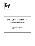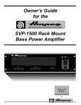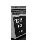
1
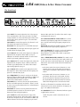
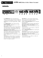
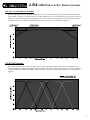
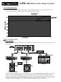
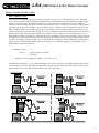
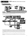
User’s Guide
for the
LS4
24dB/Octave
Active Stereo Crossover
In order to achieve the highest level of performance from your crossover,
please read this owners guide prior to its use.
“Thank You” from
LS4
24dB/Octave Active Stereo Crossover
Congratulations on the purchase of your new Crate Pro Audio LS4 Crossover. This outstanding device
has been designed with the audio professional in mind, providing the degree of accuracy and level of quality you demand. Its straight-forward design and simple operation make it easy to use by novices as well.
This owner’s guide is designed to acquaint you with the workings of the crossover and how it may be used
in your sound system and should be read through before using the unit.
Introduction:
Crate’s new LS4 is a rugged multi-purpose active crossover housed in a standard 19” single space rack
enclosure. It features pushbutton selectable two-way stereo or three-way mono operation. All inputs and
outputs are balanced for low noise operation. Each channel features parallel inputs for “daisy-chaining” two
or more units together.
The new LS4 features two Linkwitz-Riley state variable filters that include 24dB/octave slopes and a low “Q”
design for minimal ringing. Each output is in phase at the crossover point, which eliminates the need for
polarity reversal between components. The LS4 also features a 40Hz low cut filter for subsonic filtering and
a 15kHz high cut filter for reduction of hiss. The output level controls provide 6dB boost at full rotation for
weak input signals. The crossover frequency is continuously variable with between 50Hz and 1kHz or
500Hz and 10kHz. The CD Horn Equalizer switch is a special feature. This switch, when engaged, provides
a boost in the higher frequencies to compensate for the high frequency deficiencies in Constant-Directivity
horns. The inputs are both XLR and 1/4” TRS and can be used as either balanced or unbalanced inputs. All
of the outputs are 1/4” TRS jacks and can also be used either balanced or unbalanced.
Table of Contents:
Introduction ..................................................................................2
The Front Panel.............................................................................3
The Rear Panel..............................................................................4
The Low Cut and High Cut Switches ............................................5
The X1/X10 Switch .......................................................................5
The CD Horn EQ Switch...............................................................6
How to Use the Crossover:
With a Subwoofer .............................................................6
For Bi-Amping in a Single Enclosure .................................9
For Tri-Amping ................................................................11
Technical Specifications .....................................back cover
CAUTION
ATTENTION
VORSICHT
RISK OF ELECTRIC SHOCK
DO NOT OPEN
RISQUE D'ELECTROCUTION
NE PAS OUVRIR
ELEKTRISCHE SCHLAGGEFAHR
NICHT OFFENEN
CAUTION: TO REDUCE THE RISK OF ELECTRIC SHOCK,
DO NOT REMOVE COVER.
NO USER-SERVICEABLE PARTS INSIDE.
REFER SERVICING TO QUALIFIED SERVICE PERSONNEL.
ATTENTION: POUR REDUIRE D'ELECTROCUTION NE PAS
ENLEVER LE COUVERCLE. AUCUNE PIECE INTERNE N'EST REPRABLE
PAR L'UTILISATEUR. POUR TOUTE REPARATION, S'ADRESSER A UN
TECHNICIEN QUALIFIE.
VORSICHT: ZUR MINIMIERUNG ELEKTRISCHER SCHLAGGEFAHR NICHT
DEN DECKEL ABENHMEN. INTERNE TEILE KONNEN NICHT VOM
BENUTZER GEWARTET WERDEN. DIE WARTUNG IS QUALIFIZIERTEM
WARTUNGSPERSONAL ZU UBERLASSEN.
THIS EQUIPMENT HAS BEEN DESIGNED AND ENGINEERED TO PROVIDE SAFE AND RELIABLE OPERATION. IN ORDER TO PROLONG THE
LIFE OF THE UNIT AND PREVENT ACCIDENTAL DAMAGES OR INJURY, PLEASE FOLLOW THESE PRECAUTIONARY GUIDELINES:
CAUTION: TO REDUCE THE RISK OF ELECTRIC SHOCK, DO NOT OPEN CHASSIS; DO NOT DEFEAT OR REMOVE THE GROUND PIN OF THE
POWER CORD; CONNECT ONLY TO A PROPERLY GROUNDED AC POWER OUTLET.
WARNING: TO REDUCE THE RISK OF FIRE OR ELECTRIC SHOCK, DO NOT EXPOSE THIS EQUIPMENT TO RAIN OR MOISTURE.
CAUTION: NO USER-SERVICEABLE PARTS INSIDE. REFER SERVICING TO QUALIFIED SERVICE PERSONNEL.
EXPLANATION OF
GRAPHICAL SYMBOLS:
2
"DANGEROUS VOLTAGE"
= "DANGER HAUTE TENSION"
"GEFAHLICHE SPANNUNG"
"IT IS NECESSARY FOR THE USER TO REFER TO THE INSTRUCTION MANUAL"
= "REFERREZ-VOUS AU MANUAL D'UTILISATION"
"UNBEDINGT IN DER BEDIENUNGSANLEITUNG NACHSCHLAGEN"
LS4 24dB/Octave Active Stereo Crossover
The Front Panel:
1,12 - INPUT: This control adjusts the level of the input signal to accommodate a wide variety of sources. The Input
control should be set so the Peak LED (#2,#13) flashes occasionally during strong peak-level signals. The control functions as follows:
Stereo Mode: #1 controls the input level for Channel 1 and
#12 controls the input level for Channel 2.
Mono Mode: The input signal level is controlled only by #1.
2,13 - PEAK LED: This LED lights when the input signal level
is within 5dB of the clipping point.
3,14 - LOW CUT: This switch, when depressed, reduces the
amplitude of the frequencies below 40Hz at a rate of
6dB/octave to eliminate subsonic rumble. The effect of this
switch is represented graphically on page 5.
4,15 - HIGH CUT: This switch, when depressed, reduces the
amplitude of the frequencies above 15kHz to reduce hiss
and other signal abnormalities. The effect of this switch is
represented graphically on page 5.
5,16 - LOW OUT: This control sets the output level of the
low frequencies. In the Mono mode, the low frequecny output level is controlled only by #5.
6,17 - FREQUENCY: This control is used to set the desired
crossover frequency between 50Hz and 1kHz or 500Hz and
10kHz depending on the position of the X1/X10 switch
(#7,#18).The control functions as follows:
Stereo Mode: #6 is used to set the crossover point between
the low- and mid-frequencies for channel 1 and #17 is used
to set the crossover point between the low- and mid-frequencies for channel 2.
Mono Mode: #6 sets the crossover point between the lowand mid-frequencies and #17 sets the crossover point
between the mid- and high-frequencies.
7,18 - X1/X10: This switch determines the range of the
Frequency controls (#6,#17). When this switch is depressed,
the crossover frequency may be varied between 500Hz and
10kHz. Otherwise the crossover frequency may be varied
between 50Hz and 1kHz. The effect of this switch is represented graphically on page 5.
8,19 - HIGH OUT/MID OUT: Stereo mode: #8 is used to
control the high frequency output level for Channel 1and
#19 is used to control the high frequency output level for
Channel 2.
Mono mode: #8 controls the middle frequency output level
and #19 controls the high frequency output level.
9,20 - CD HORN EQ: This switch is used to add 12dB boost
to the upper frequencies to compensate for ConstantDirectivity horns. The effect of this switch is represented
graphically on page 6.
10,11 - STEREO/MONO LEDS, SWITCH: This switch is used
to set the crossover in the two-way stereo mode (switch out)
or three-way mono mode (switch depressed). The upper LED
indicates the Stereo mode and the lower LED indicates the
Mono mode.
•In the Stereo mode, the crossover functions as a twochannel, two-way unit. In this mode, the function of
each control is annotated in black above the affected
control.
•In the Mono mode, the crossover functions as a single-channel, three-way unit. In this mode, the function of each control is annotated in the grey accent
box located below the affected control. The controls
labeled #12 through #16 are not used in this mode.
The LEDs are illuminated in accordance with the mode
selected. (Refer to the section entitled “For Tri-Amping” on
page 11 for additional information.)
21 - POWER LED: This LED is illuminated whenever power
is applied to the crossover.
NOTE: The power switch is located on the rear of
the unit.
3
LS4 24dB/Octave Active Stereo Crossover
The Rear Panel:
22 - POWER JACK: Plug the small end of the AC
adapter into this jack. Plug the other end of adapter into
a suitable source of the proper AC voltage, as indicated
on the adapter. Use only the supplied 10VAC, 1400mA
adapter.
23 - POWER SWITCH: Use this switch to turn the
crossover on and off.
24, 28 - HIGH OUT / MID OUT: These 1/4” mono
jacks are used as follows:
Stereo mode: #24 sends the Channel 2 high frequency
signal to the channel 2 high frequency amplifier and
#28 sends the Channel 1 high frequency signal to the
channel 1 high frequency amplifier.
Mono mode: #24 sends the high frequency signal to the
high frequency amplifier and #28 sends the mid frequency signal to the mid frequency amplifier. (See the
section entitled “For Tri-Amping” on page 11).
25, 29 - LOW OUT: These 1/4” mono jacks are used as
follows:
Stereo mode: #25 sends the Channel 2 low frequency
signal to the channel 2 low frequency amplifier and
#29 sends the Channel 1 low frequency signal to the
channel 1 low frequency amplifier.
4
Mono mode: #25 is not used. #29 sends the low frequency signal to the low frequency amplifier. (See the
section entitled “For Tri-Amping” on page 11).
26, 30 - 1/4” BALANCED INPUT: These 1/4” TRS jacks
are used as follows:
Stereo mode: #26 feeds the channel 2 input signal into
the crossover’s Channel 2 and #30 feeds the channel 1
input signal into the crossover’s Channel 1.
Mono mode: #26 is not used. #30 feeds the input signal
into the crossover.
(Use the 1/4” jacks for shorter cable runs, or when XLR
connectors are unavailable.)
27, 31 - XLR BALANCED INPUT: These 3-pin XLR jacks
are used as follows:
Stereo mode: #27 feeds the channel 2 input signal into
the crossover’s Channel 2 and #31 feeds the channel 1
input signal into the crossover’s Channel 1.
Mono mode: #27 is not used. #31 feeds the input signal
into the crossover.
(Use the XLR jacks for long cable runs, or when 1/4”
connectors are unavailable.)
LS4 24dB/Octave Active Stereo Crossover
The Low Cut and High Cut Switches:
The Low Cut switch (#3,#14) provides a 6dB/octave cut in the amplitude of signals below 40Hz to eliminate subsonic rumble. The High Cut switch (#4,#15) provides a 6dB/octave cut in the amplitude of signals above 15kHz to
reduce hiss and other unwanted high frequency noise. These circuits are engaged when their respective switches
are depressed. The chart below illustrates the effect these switches have on frequency response.
The X1/X10 Switches:
The X1/X10 switch (#7,#18) varies the range of the crossover frequency. When this switch is not depressed, the
crossover frequency is adjustable between 50Hz and 1kHz. When this switch is depressed, the crossover frequency
is adjustable between 500Hz and 10kHz. The chart below illustrates the effect these switches have on frequency
response.
5
LS4 24dB/Octave Active Stereo Crossover
The CD Horn EQ Switch:
The CD Horn EQ switch (#9,#20) allows the user to boost the upper frequencies by 12dB to compensate for
Constant-Directivity horns. The chart below illustrates the effect of this switch.
How to Use the Crossover:
With a Subwoofer:
Adding a subwoofer requires an additional power amplifier and a couple of cables. The basic connections are illustrated below.
6
Connect the line level output of your source (mixer, preamp, etc.) to the CHANNEL ONE BALANCED INPUT of the LS4 (A).
Connect the LS4’s CHANNEL ONE LOW OUT to the input jack of the amplifier which will be used to power the subwoofer (B). Connect the LS4’s CHANNEL ONE HIGH OUT to the input jack of the amplifier which will be used to power
the upper range speaker cabinet (C). (Hint: Label the amplifiers “subwoofer amp” and “upper range amp” to avoid
confusion.) Connect the amplifiers to their respective speakers. Repeat for channel two if used.
LS4 24dB/Octave Active Stereo Crossover
How to Use the Crossover (con’t):
With a Subwoofer (con’t):
Before turning the amplifiers on, you will need to set up the crossover. First, set the Input level to “10” (full clockwise). Set the Frequency control to properly match the spatial relationship between the subwoofer and upper range
cabinet. For the subwoofer, the frequency will be low, so make sure the X1/X10 switch is OUT. Start with the
Frequency control at 50Hz, then adjust as needed. Most subwoofers have a useful range of 30Hz to 150Hz, depending on the type of design. For example, a direct-radiating single 18” speaker can have a frequency response on the
order of 30Hz to 1kHz. For a bandpass design, the range may be as small as 30Hz to 100Hz. (Please refer to your
speaker manufacturer’s specifications.) Ideally, the crossover frequency can be determined by the location of the two
speaker cabinets (the subwoofer and the upper range cabinet). If the two cabinets are in close proximity to each
other and the front faces are aligned, a relatively high crossover frequency can be used, provided you do not exceed
the upper limits of the subwoofer. When the subwoofer is not in close proximity to the upper range speaker cabinet,
in order to avoid phase cancellation the crossover should be set to a frequency whose wavelength is greater than or
equal to twice the distance between the cabinets (greater than 1/2 wavelength separation.). Wavelength can be
determined by the following formula:
wavelength (in feet)
=
c/ƒ
where: c
ƒ
=
=
speed of sound (1130 ft/sec)
frequency
Example: crossover frequency of 100Hz: 1130 / 100 = 11.3 ft
At 100Hz the wavelength is 11.3 feet. If the subwoofer is not in close proximity to the upper range speaker, no drastic cancellations will occur. The further the subwoofer is moved forward or backwards, the lower the crossover frequency needs to be. Left to right orientation does not have the same effect.
7
LS4 24dB/Octave Active Stereo Crossover
How to Use the Crossover (con’t):
With a Subwoofer (con’t):
Now you are ready to adjust the output levels. The easiest way to balance your system is to look at the manufacturer’s specifications of your speaker enclosures. Most manufacturers will give a sensitivity spec in terms of one watt
input power at a distance of one meter. For example, if your subwoofer has a sensitivity of 95dB 1W/1m and your
upper range enclosure has a sensitivity of 100dB 1W/1m, then the difference in acoustic output between the two
speakers is 5dB. With your LS4, you can accurately adjust the High Out control down 5dB less than the Low Out
control to compensate for this difference, provided the outputs from the power amps are the same.
Another way to balance your system is to use a pink noise source. This source may be obtained from a test CD.
Position an SPL meter at the center axis of your system at a distance of about 10 feet (refer to the illustration below)
and follow these steps:
• Make sure that all equalization in your system is either set flat or bypassed.
• Set the Input level of the LS4 at “10” and the Outputs all the way down.
• Turn up the low output level to “0dB” and measure the average SPL on your meter. Record the measurement.
• Turn the Low Out level of the LS4 back down again.
• Turn the High Out level up until the meter reads the same level as the subwoofer.
Of course, this will only get the two speakers close to an electrical balance and more equalization will be required
to achieve the best sound and balance.
A more accurate balance can be achieved by using a Real-Time Analyzer. The set up is basically the same as
shown above, but both speakers can be measured in real time. With the pink noise source on, adjust the Low and
High Out levels until they appear balanced on the analyzer screen. Once the levels are balanced you are then
ready to continue equalization of the system.
8
LS4 24dB/Octave Active Stereo Crossover
How to Use the Crossover:
For Bi-Amping in a Single Enclosure:
IMPORTANT NOTE: Whether you are bypassing the internal passive
crossover of an existing enclosure or building your own system, care
must be taken not to exceed the limitations of the speaker components!
For bi-amping in a single enclosure, the basic connections are illustrated below.
Connect the line level output of your source (mixer, preamp, etc.) to the CHANNEL ONE BALANCED INPUT of the LS4 (A).
Connect the LS4’s CHANNEL ONE LOW OUT to the input jack of the amplifier which will be used to power the low frequency section of the enclosure (B). Connect the LS4’s CHANNEL ONE HIGH OUT to the input jack of the amplifier
which will be used to power the upper frequency section of the enclosure (C). (Hint: Label the amplifiers “low freq
amp” and “high freq amp” to avoid confusion.) Connect the amplifiers to the respective input jacks of the enclosure. Repeat for channel two if used.
Before you operate your system, set the appropriate crossover frequency. Check the speaker manufacturer’s specifications for minimum crossover frequency and power handling! This information is usually printed on or near the
input jackplate. Most manufacturers of horn loaded compression drivers will list the lowest recommended
crossover frequency accompanied by the maximum power the unit will handle with different horn types. A good
rule of thumb is to stay above the recommended frequency. In addition, when using a crossover between a cone
type loudspeaker and a horn, pay attention to the full range dispersion pattern. For example, a typical 15” diameter
loudspeaker will begin to beam above 800Hz – that is, at frequencies above 800Hz its dispersion angle begins to
decrease, causing a drop in SPL off axis. (See the illustrations on the following page.) The table on the following
page shows different diameter cone loudspeakers and their typical dispersion characteristics. If the horn you are
using has a horizontal dispersion of 90˚, then a crossover point should be selected to provide a smooth transition
from the cone speaker to the horn. This will insure a predictable off-axis response (refer to the illustration on the
following page).
WARNING: Do not exceed the lower crossover frequency limits of your high frequency component or it may get
damaged!
9
LS4 24dB/Octave Active Stereo Crossover
How to Use the Crossover (con’t):
For Bi-Amping in a Single Enclosure (con’t):
The dispersion characteristics of a typical speaker and horn are illustrated below:
This chart illustrates different diameter cone loudspeakers and their typical dispersion characteristics:
As previously stated, system balance is very important. Check your speaker manufacturer’s specifications for the sensitivity of each driver and balance the system as described on page 8 using pink noise and/or a Real-Time Analyzer
in conjunction with an SPL meter. Signal delays may be needed between the crossover and the power amps to correct driver offset (for example, between a cone type loudspeaker and a horn), to minimize any phase cancellations
around the crossover frequency (see the illustration on the facing page). Once properly balanced, the system will
need to be equalized.
10
LS4
24dB/Octave Active Stereo Crossover
How to Use the Crossover (con’t):
For Bi-Amping in a Single Enclosure (con’t):
Use of a signal delay processor may be necessary to correct the time alignment of the components:
For Tri-Amping:
IMPORTANT NOTE: Whether you are bypassing the internal passive crossover of an existing enclosure or
building your own system, care must be taken not to exceed the limitations of the speaker components!
The LS4 features a 3-way mono mode that can be activated by pressing in the Stereo/Mono switch (#11). This
switch internally connects the two channels together providing a Low, Mid and High output. In the Mono mode the
controls function according to the labeling directly beneath them (in light gray boxes), and the rear panel outputs
carry the signals indicated by the labeling directly beneath the jacks.
The basic connections are illustrated below.
Refer to the nomenclature beneath the jacks. Connect the line level output of your source (mixer, preamp, etc.)
to the BALANCED INPUT - MONO MODE of the LS4 (A). Connect the LS4’s LOW OUT - MONO MODE to the input jack of
the amplifier which will be used to power the low frequency driver (B). Connect the LS4’s MID OUT - MONO MODE
to the input jack of the amplifier which will be used to power the midrange driver (C). Connect the LS4’s HIGH
OUT - MONO MODE to the input jack of the amplifier which will be used to power the high frequency driver (D).
(Hint: Label the amplifiers to avoid confusion.) Connect the amplifiers to the respective input jacks of the enclosure(s).
The Channel One Frequency control sets the crossover frequency between the low and mid outputs; Channel
Two sets the crossover frequency between the mid and high outputs. The system is now ready for balancing and
equalizing.
11
LS4
24dB/Octave Active Stereo Crossover
Technical Specifications
Filter Type
Two 24dB/octave Linkwitz-Riley state variable filters
Control Range
50 - 1kHz (X1)
500 - 10kHz (X10)
3-Way Mono Mode Operation
Internally Wired
Input Impedance10k ohms
Input Connections
Balanced XLR & 1/4” T/R/S
Output Impedance
2.2k ohms
Output Connections
1/4” T/R/S
Input Gain
0dB @ “10”
Output Gain (all Outputs)
6dB
Maximum Input Level Accepted
+21dBm (0dB = 0.775V rms)
Maximum Output Level
+21dBm (0dB = 0.775V rms)
Signal to Noise Ratio
>98dB
Total Harmonic Distortion
0.01% @ 1kHz
Common Mode Rejection Ratio
>50dB @ 1kHz
Power Requirements
10VAC @ 1400mA 50/60Hz
Size (H x W x D)
1.75” x 19” x 6”
Weight
4 lbs.
Due to ongoing product development and improvement, the specifications
contained herein are subject to change without notice.
www.crateamps.com
©1999 SLM Electronics, Inc. • A Division of St. Louis Music, Inc.
1400 Ferguson Avenue • St. Louis, MO 63133
47-507-03 • 04/99