1
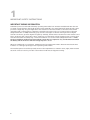
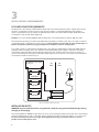
Pure Sine Wave
Power Inverter
SSW-350-12A
SSW-600-12A
SSW-1000-12A
SSW-1500-12A
SSW-2000-12A
Owner's
Manual
Please read
this manual
before
operating
your inverter
INDEX
1.
Important Safety Instructions............................. 3
2.
How Your Inverter Works................................... 5
3.
Installation / Environments................................. 6
4.
Operating Tips..................................................... 10
5.
Protective Features of the Inverter.................... 12
6.
Special Features................................................... 13
7.
Troubleshooting Guide....................................... 14
8.
Fuse Replacement............................................... 16
9.
Specifications....................................................... 17
10. Warranty.............................................................. 18
2
1
IMPORTANT SAFETY INSTRUCTIONS
THIS MANUAL CONTAINS IMPORTANT INFORMATION REGARDING SAFETY, OPERATION,
MAINTENANCE AND STORAGE OF THIS PRODUCT. BEFORE USE, READ AND UNDERSTAND ALL
CAUTIONS, WARNINGS, INSTRUCTIONS AND PRODUCT LABELS, PLUS YOUR VEHICLE’S BATTERY
MANUFACTURER GUIDELINES. FAILURE TO DO SO COULD RESULT IN INJURY AND/OR PROPERTY
DAMAGE.
To ensure reliable service, your power inverter must be installed and used properly. Please read the installation
and operating instructions thoroughly prior to installation and use. Pay particular attention to the WARNING
and CAUTION statements in this manual. The CAUTION statements advise against certain conditions and
practices that may result in damage to your inverter. The WARNING statements identify conditions or practices
that may result in personal injury. Read All Instructions Before Using This Power Inverter!
WARNINGS
TO REDUCE THE RISK OF FIRE, ELECTRIC SHOCK, EXPLOSION OR INJURY
1. Do not connect to AC distribution wiring. This inverter is NOT grid interactive.
2. Remove appliance plug from outlet strip or turn off inverter before working on the appliance. Multiple
outlet power strips with switches and circuit breakers only interrupt power to the “hot” receptacle
terminals. For SSW-350-12A & SSW-600-12A, the “Neutral” terminals remain powered with respect to
the “Ground” terminals.
3. Do not make any electrical connections or disconnections in areas designated as IGNITION PROTECTED.
This includes 12 V DC cigarette plug connections, and terminal connections.
4. This is not a toy - keep away from children.
5. DO NOT install object into air vents.
CAUTIONS
1. The chassis and the input Negative terminal of the inverter are internally connected to the AC Ground.
Hence, the input Negative terminal should be used as the grounding terminal. Do not use with Positive
Grounded Electrical Systems (the majority of modern automobiles, RVs, trucks and boats are Negative
Grounded Electrical Systems).
2. Observe correct polarity when connecting the DC input terminals of the inverter to the battery. Connect
Positive of the battery to the Positive input connector of the inverter and the Negative of the battery to
the Negative input terminal of the inverter. Reverse polarity connection will result in a blown fuse and
may cause permanent damage to the inverter. Damage due to reverse polarity is not covered under
warranty.
3. This inverter will not operate high wattage appliances that exceed the output power limit or the surge
power limit.
4. For SSW-350-12A & SSW-600-12A, grounding the Neutral will cause the inverter to shut down. Hence,
do not connect the Neutral of the AC output receptacles to Ground.
5. Do not operate this inverter if it is wet.
6. Do not install in engine compartment – please install in a well ventilated area.
7. This inverter is not tested for use with medical devices.
3
1
IMPORTANT SAFETY INSTRUCTIONS
IMPORTANT WIRING INFORMATION
Substantial power loss and reduced battery operating time results from inverters installed with wires that are
not sized correctly based on the length and the current required to be carried. Current flowing through a wire
produces voltage drop along its length due to the resistance of the wire and due to the value of the current
carried through it. The resistance of the wire is inversely proportional to the cross-sectional area of the wire
(designated in mm2 or AWG) and directly proportional to its length i.e. thinner and longer wire has higher
resistance and hence, produces higher voltage drop. Similarly, thicker and shorter wire has lower resistance and
hence, produces lower voltage drop. Hence, symptoms of low DC input voltage / battery power can result from
wires that are either excessively long or have an insufficient cross-sectional area (designated in mm2 or AWG).
The wires should be sized based on the maximum current they are required to carry and the distance between
the battery and the inverter to limit the voltage drop to 2% to 5%.
Wires are rated based on its insulation, temperature and operating environment. Please ensure that the wire
insulation is of the appropriate type for the operating environment.
The installer/operator should be especially aware of the requirements to maintain secure, tight, water-resistant
electrical connections and to provide for strain relief for DC wires and appliance wiring.
4
2
HOW YOUR INVERTER WORKS
The inverter converts low voltage DC (Direct Current) from a battery or other DC power source to the standard
nominal 115 volt AC (Alternating Current) household power.
DESIGN FEATURES
•
•
•
•
•
High efficiency
Compact size
Low Idle current
Soft Start Technology
LCD Remote Control (for 1000 W, 1500 W & 2000 W models).
POWER RATINGS
The continuous power ratings of the models are as follows:
• SSW-350-12A
-
350 Watts
• SSW-600-12A
-
600 Watts
• SSW-1000-12A
-
1000 Watts
• SSW-1500-12A
-
1500 Watts
• SSW-2000-12A
-
2000 Watts
PRINCIPLE OF OPERATION
The inverter converts power in two stages. The first stage is a DC to DC conversion process that raises the
low voltage DC at the inverter input to high voltage DC of approximately 150 VDC. The second stage is the
actual inverter stage that converts the high voltage DC into nominal 115 VAC, 60 Hz AC (RMS). The DC-toDC converter stage uses modern high frequency power conversion techniques that have replaced the bulky
transformers found in less technologically-advanced models. The inverter stage uses advanced power MOSFET
transistors in a high frequency full bridge configuration.
THE OUTPUT WAVEFORM
The AC output waveform of the SSW-series inverter is known as “Pure Sine Wave” or “True Sine Wave”. It is a
waveform that has characteristics same to the sine wave shape of utility power (See Fig. 1).
1.0
0.5
-6
-4
-2
2
4
6
- 0.5
- 1.0
Fig.1. Pure Sine Wave Waveform
5
3
INSTALLATION / ENVIRONMENTS
DC POWER SOURCE REQUIREMENTS
The DC power source must provide between 10.5 and 15.5 Volts DC and must be able to supply the necessary
current to operate the load. The power source may be a battery or a well-regulated DC power supply. To
obtain a rough estimate of the current (in Amperes) the power source must deliver, simply divide the power
consumption of the load (in Watts AC) by 10.
Example: if a load is rated at 100 Watts AC, the DC power source must be able to deliver: 100 / 10 = 10A.
The inverter will provide you nominal 115 VAC when powered by a 12 VDC source such as is found in a vehicle
or multiple battery configurations as shown in Fig. 2. This manual does not describe all of the possible types of
battery configurations, battery charging configurations and battery isolation configurations.
For normal operation of the inverter, the DC power source must provide between 11.0 and 15.0 VDC and the
required current. This DC power source must be a well-regulated DC power supply or alternator and deep
cycle battery system typically found in vehicles and marine crafts. The DC power source may also be two or
more 12 volt batteries connected in parallel. On larger applications, the power source may be several batteries
connected in parallel as shown in Fig. 2.
BATTERIES CHARGING FROM
COMMERCIAL AC-DC, ENGINE,
SOLAR, ETC.
AC
SIDE
FUSE
BATTERY
DC
SIDE
BATTERY
POWER INVERTER
BATTERY
Fig.2. Connecting to a DC Power Source
INSTALLATION NOTES
WARNING: Ensure ventilation when using batteries. Batteries may generate flammable gas during
charging or discharging.
The inverter (350 W to 2000 W models) has four slots in its mounting bracket that allow the unit to be fastened
against a bulkhead, floor, wall or other flat surface. Ideally, the mounting surface should be cool to the touch.
It is more electrically efficient to use longer AC wiring than DC wiring, so install the inverter as close as
possible to the 12 VDC power source.
6
3
INSTALLATION / ENVIRONMENTS
The inverter can be operated in any position, however, if it is to be mounted on a wall, mount it horizontally
(Fig 3a) so that indicators, switches, outlets and terminal blocks located on the front panel are visible and
accessible. Do not mount on wall in positions shown in Figs. 3 (b) & 3(c). If the inverter is to be installed in a
moving vehicle, we strongly recommend that the inverter be shock-mounted either on the floor (in a clear, safe
area) or on a secure flat surface
(Fig 3a)
(a)
(b)
(c)
Fig. 3 Mounting arrangement on wall
CAUTION
The power inverter must be connected only to batteries with a nominal output voltage of 12 V. The unit will
not operate from a 6 Volt battery, and will sustain permanent damage if connected to a 24 V battery.
CAUTION
Loose connectors may cause overheated wires and melted insulation. Check to make sure you have not
reversed the polarity. Reverse polarity connection will result in a blown fuse and may cause permanent damage
to the inverter. Damage due to reverse polarity is not covered by warranty.
CONNECTING TO A DC POWER SOURCE
Please ensure that the DC side wires and external fuses are selected as given below.
Note that an external fuse is required to protect the battery wires from short circuit. A battery is an unlimited
source of current and can deliver extremely high (up to 10,000 A of current) into a short circuit that will melt
the wires and cause fire hazard.
Current limiting fuse with Ampere Interrupting Capacity (AIC) of 10000 A or more or Class T fuse is, therefore,
recommended.
External FUSE and DC wire selection
WATTAGE OF THE
INVERTER
CAPACITY OF THE
FUSE
350W
600W
1000W
1500W
2000W
50A
80A
150A
200A
300A
RECOMMENDED MODEL
NO. OF FUSE ASSEMBLY
MANUFACTURED BY SAMLEX
AMERICA, INC.
DC-FA-200
DC-FA-300
WIRE SIZE (AWG)
MAX DISTANCE
BETWEEN INVERTER
AND THE BATTERY
#8
#6
#4
#2
2 X #2
1.5M
1.5M
1.2M
1.2M
1.0M
7
3
INSTALLATION / ENVIRONMENTS
CONNECTING WIRES FOR BATTERY INPUT POWER - SSW-350-12A & SSW-600-12A
For convenience of providing DC input power from the battery, the 350 W Model No. SSW-350-12A and the
600 W Model No. SSW-600-12A are provided with the following DC connecting wires:
• SSW-600-12A
- 3 ft. long pair of Positive and Negative wires with battery clamps
• SSW-350-12A
- 3 ft. long pair of Positive and Negative wires with battery clamps
When using these wires, please ensure that appropriate DC fuses are used as recommended in the Table on
page 7.
CONNECTING WIRES FOR BATTERY INPUT POWER – SSW-1000-12A, SSW-1500-12A & SSW-2000-12A
DC side connecting wires have not been provided for these inverters and these have to be arranged by the end
user. Please use the appropriate sizes of wires and fuses as per recommendations provided in the Table given
on page 7.
Crimp / solder appropriate ring type of lugs on the wire ends that connect to the DC side input terminals to suit
the size of the wire and the M9 stud.
DC SIDE INPUT TERMINALS
The following DC side input terminals have been provided:
• SSW-350-12A & SSW-600-12A
• SSW-1000-12A, SSW-1500-12A, SSW-200-12A
- Thumb screw – size M4
- Stud and nut – size M9
MAKING DC SIDE CONNECTIONS
1. Ensure that appropriate terminal lugs are used and are properly crimped / soldered at the bare ends of
the wires for secure connections.
2. Ensure that the inverter’s power switch is turned off and that no flammable fumes are present.
3. Identify the Positive (+) and Negative (-) terminals of the 12 V battery or other DC source.
4. Install a fuse holder or breaker close to the Positive (+) terminal of the battery (or other DC source)
(preferably within 7” of the terminal) .
5. Cut an appropriate short piece of the selected Positive wire and use this to piece to connect the Positive
terminal of the battery (or other DC source) to one terminal of the fuse holder or breaker. Connect one
end of the remaining length of wire to the other terminal of the fuse holder or breaker. Connect the
other end of the wire to the Positive terminal of the inverter.
6. Connect the selected length of Negative wire between the Negative terminal of the battery (or other DC
source) and the Negative (-) terminal of the inverter.
7. Insert a suitable fuse in the fuse holder.
8. Check to be sure that all connections are secure and tight.
9. Test the inverter by turning it on and plugging in a 100 Watt lamp or equipment.
10. If the inverter is not properly operating, then refer to the Troubleshooting Guide at page 14 of this
manual.
CAUTION: Loose connectors may cause overheated wires and melted insulation.
SWITCHING ON AND SWITCHING OFF ON LOAD
Please ensure that the following procedure is used for switching on and switching off the inverter when a load
is already connected to the inverter:
8
3
INSTALLATION / ENVIRONMENTS
Switching on
1.
2.
3.
4.
Switch off the load connected to the inverter
Switch on the inverter
Wait for a few seconds
Switch on the load
Switching off
1. Switch off the load connected to the inverter
2. Switch off the inverter
CONNECTING LOADS
1. Make sure that the single load or the combined load requirement of your equipment does not exceed
the inverter’s output rating.
2. Switch off the inverter
3. Switch off the load
4. Plug the cord(s) from the load(s) into the AC receptacle(s) of the inverter
5. Switch on the inverter. Wait for a few seconds
6. The green LED indicator will be lighted to indicate that the inverter is functioning
7. Switch on the load(s)
The inverter is engineered to be connected directly to standard electrical and electronic equipment in the
manner described above. Do not connect the power inverter to household or RV AC distribution wiring. Do
not connect the power inverter to any AC load circuit in which the Neutral conductor is connected to Ground
(Earth) or to the Negative of the DC (battery) source.
WARNING: Do not connect directly to AC distribution wiring. This inverter is NOT grid interactive.
OPERATING ENVIRONMENT
For best operating results, the inverter should be placed on flat surface, such as the ground, car floor, or other
solid surface. The power cord allows easy positioning of the inverter. The inverter should only be used in
locations that meet the following criteria:
DRY
Do not allow water and/or other liquids to come into contact with the power inverter. In all marine
applications, do not install the inverter below or near the waterline and keep the inverter away from moisture
or water.
COOL
Ambient air temperature should be between 30 degrees F (-1 degree C) non-condensing, and 105 degrees F (40
degrees C). Do not place the inverter on or near a heating vent or any piece of equipment which is generating
heat above room temperature. Keep the inverter away from direct sunlight, if at all possible.
VENTILATED
The unit is cooled by load controlled fan (s). The fan(s) will be normally switched off at low loads to conserve
battery power and will be switched on automatically once the load reaches a certain threshold. Keep the area
surrounding the inverter clear to ensure free air circulation around the unit. Do not place items on or over
the inverter during operation. An additional external fan is helpful if the inverter is operating at maximum
power outputs for extended periods of time. The unit will shut down if the internal temperature exceeds the
operating temperatures. The unit will restart after it cools.
SAFE
Do not use the inverter near flammable materials or in any locations that may accumulate flammable fumes of
gases.
9
4
OPERATING TIPS
RATED VERSUS ACTUAL CURRENT DRAW OF EQUIPMENT
Most electrical tools, appliances and audio/video equipment have labels that indicate the power consumption
in Amps or Watts. Be sure that the power consumption of the item you wish to operate is less than inverter’s
power. (If the power consumption is rated in Amps AC, simply multiply by the AC Volts (115) to determine the
approximate Wattage). The inverter will shut down if it is overloaded. The overload must be removed before
the inverter will restart. Resistive loads are the easiest for the inverter to run. However, larger resistive loads,
such as electric stoves or heaters, usually require more wattage than the inverter can deliver. Inductive loads,
such as TV’s and stereos, require more current to operate than do resistive loads of the same wattage rating.
Induction motors, as well as some televisions, may require 2 to 6 times their wattage rating to start up. The
most demanding in this category are those that start under load, such as compressors and pumps. To restart the
unit after a shutdown due to overloading, remove the overload if necessary turn the power switch OFF, wait
for at least 3 minutes and then switch ON again.
SIZING CHART FOR TYPICAL LOADS THAT REQUIRE HIGH STARTING SURGE
The manufacturers’ specifications of the appliances and devices indicate only the running power required.
The surge power required by some specific types of devices has to be checked with the manufacturer, actually
tested or guessed at best.
The Table below lists some common loads that require high surge power on start up. A “Sizing Factor” has
been recommended against each which is a Multiplication Factor to be applied to the rated running Watt
rating of the load to arrive at the continuous power rating of the inverter (Multiply the running Watts of the
device / appliance by the Sizing Factor).
TYPE OF DEVICE OR APPLIANCE
SIZING FACTOR
Air conditioner
5
Refrigerator / Freezer (Compressor based)
5
Air Compressor
4
Sump Pump / Well Pump / Submersible Pump
3
Dishwasher
3
Clothes Washer
3
Microwave (In cases where the rated output power is the cooking power)
2
Furnace Fan
3
Industrial Motor
3
Portable Kerosene / Diesel Fuel Heater
3
Circular Saw
3
Bench Grinder
3
Incandescent / Halogen / Quartz Lamps
3
Laser Printer / Other Devices using Quartz Lamps for heating
3
Switched Mode Power Supplies
3
Photographic Strobe / Flash Lights (with respect to its Watt Sec rating)
4*
* In the case of photographic strobe / flash unit, the RMS surge power of the inverter should be more than 4 times the Watt Sec
rating of the unit.
10
4
OPERATING TIPS
DETERMINING BATTERY SIZE
The power inverter will require DEEP CYCLE lead acid batteries of appropriate capacity.
The automotive SLI (Starting/lighting/Ignition) battery is not designed for repeated deep discharge. The SLI
battery may not supply enough energy and its service life may be reduced.
To determine the minimum battery size that you will need to operate appliances, follow these steps:
1. Determine the AC wattage of each appliance and / or tool you will need to simultaneously operate from
the inverter. To do this, read the labels on the equipment to be operated. Usually, power consumption is
shown in Watts. If it is shown in Amps, multiply by 115 to determine the AC wattage.
2. For each appliance, estimate the number of hours the appliance will be in use between battery
recharges.
3. For each appliance, determine the Watt-Hours of energy required by multiplying the AC wattage by the
number of hours of use.
4. Add the Watt-Hours of energy for each appliance to get the total Watt-Hours of energy for all
appliances to be used.
5. Divide the total Watt-Hours of energy on the AC side by 10 to get the total Ampere-Hour of energy on
the 12 VDC side to support the operation of the appliances.
6. The Ampere-Hour (AH) capacity of the battery should be 2 times the total Ampere-Hour energy required
on the 12 VDC side to support the operation of the devices (as calculated at step 5 above). Two times
factor is necessary because batteries are normally not discharged below 50% capacity.
To get an estimate of the current (in Amps) that the battery is delivering, divide the load's AC consumption
power (in Watts) by (10).
Keep in mind that most appliances are not operating for long periods of time. For example, a typical homeuse coffee maker draws 500 Watts during its brew time of 5 minutes, but it maintains the temperature of the
pot at about 100 Watts. Typical use of a microwave is only for a few minutes, sometimes at low power. Some
exceptions to brief operating times are TVs, computers etc.
In most instances, the inverter can be left connected to the battery when not in use, make sure power switch is
in the OFF position.
Battery performance drops in low temperature environment. Higher capacity batteries should be installed if
the environmental temperature is below 20oC.
11
5
PROTECTIVE FEATURES OF THE INVERTER
OVER TEMPERATURE PROTECTION
The unit is cooled by load controlled fan (s). The fan(s) will be normally switched off at low loads to conserve
battery power and will be switched on automatically once the load reaches a certain threshold. In case the fan
fails or if the cooling is inadequate due to higher ambient temperature or restricted air flow, the temperature
inside the inverter will be too high and the unit will automatically shut down. Allow the unit to cool for at
least 15 minutes before restarting after a heat-related shutdown. Unplug unit while cooling.
LOW BATTERY VOLTAGE PROTECTION
This condition is not harmful to the inverter but could damage the power source. The inverter automatically
shuts down when input voltage drops to 10.5 Volts.
OVER VOLTAGE PROTECTION
The inverter will automatically shut down when the input voltage exceeds 15.3 Volts DC. Input voltage
exceeding 16 Volts could damage the inverter.
OVERLOAD PROTECTION
The inverter will automatically shut down when the continuous draw exceeds rated Watts.
SHORT CIRCUIT PROTECTION
The inverter will shut down. Remove the short circuit and restart inverter.
EARTH FAULT PROTECTION
This inverter complies with the standard current leakage allowance. When large current leakage to earth
terminal occurs, the protection circuit activates and shuts down the inverter, which prevents electric shock to
humans. Turn OFF the inverter, unplug the fault AC appliance and then turn ON is the only way to restart it.
The 1000, 1500 and 2000 W models are provided with a GFCI that will trip in case of any leakage on the load
side. The GFCI will be required to be reset
LOW INPUT VOLTAGE ALARM
An alarm will sound when the voltage at the input terminals of the inverter drops to 11.0 Volts. This is an
indication that either the battery terminal voltage has dropped due to its discharged condition and needs to
be re-charged OR there is an excessive voltage drop across the wires connecting the inverter to the battery
(due to use of thinner and longer length of wires that will produce higher voltage drop at higher loads OR due
to loose connections). The user should stop operation of the electronic device at this time since the inverter will
shut down automatically shortly thereafter, when the input voltage at the inverter further drops to 10.5 Volts.
In case the alarm is due to the discharged condition of the battery, start your engine to recharge the battery /
use an appropriate battery charger.
If the low voltage alarm sounds when the battery is fully charged, follow the steps for solving lack of output
power in the Troubleshooting Guide at page 14.
NOTE: It is normal for the alarm to sound while the unit is being connected to or disconnected from
the power source. This is not indicative of a problem.
12
6
SPECIAL FEATURES
USB PORT (1)
REMOTE
CONTROL PORT (2)
OUTPUT
GFCI OUTLET
DC TERMINAL
COVER (3)
LOAD
CONTROLLED
FAN
350W
YES
NO
NO
NO
YES
600W
YES
NO
NO
NO
YES
1000W
NO
YES
YES
YES
YES
1500W
NO
YES
YES
YES
YES
2000W
NO
YES
YES
YES
YES
(1) Standard USB charging port +5 VDC, 500mA
(2) Compatible with specific SAMLEX SSW-series remote control only. Connection with incompatible remote /
wire will damage the power inverter / remote.
(3) DC Terminal Plastic Covers and Nuts are for terminal protection only, not for wire connection.
13
7
TROUBLESHOOTING GUIDE
Table. INVERTER POWER SWITCH TURNED ON
TROUBLE/ INDICATION
No AC output:
--Yellow LED is lit
--Red and Green LEDs are not lit
--No audible alarm is sounded
POSSIBLE CAUSE
Inverter has overheated and
thermal shutdown has been
activated
SUGGESTED REMEDY
Remove or reduce the load and wait
for the inverter to cool down.
The inverter will be latched in shut
down conditions and will require
manual reset once it has cooled down
sufficiently.
To reset, switch off, wait for 3 min. and
switch on again.
No AC output:
--Red, Yellow & Green LEDs are not lit
--No audible alarm
Non-continuous AC output:
--Red LED is lit on & off
--Green LED is lit on & off
--Yellow LED is not lit
--No audible alarm
No AC output (latch up):
--Red LED is lit
--Yellow and Green LEDs are not lit
--No audible alarm
No AC output (For SSW-1000, 1500 and 2000
with GFCI)
--Small green LED mounted on the GFCI
outlet is not lit
--Green LED on the inverter is lit
--Red and Yellow LEDs are not lit
--No audible alarm
14
DC side wires are loose OR
external DC side fuse has opened
OR the Inverter’s internal DC side
fuses have open
Check DC side wire connection and
fuses OR contact technical support
Inverter output power limited
by overload / surge circuit
protection circuit
Reduce load.
Inverter has shut down due to
overload
Reduce the load or disconnect the load
that causes overloading.
In Models SSW-350 and SSW-600
this shut down could also be
due to ground fault on the load
side (These models have built in
Ground Fault Protection Circuit).
In case of SSW-350 / SSW-600, also
check for Ground fault on the load
side
AC output side of the GFCI
protected outlet has been
mechanically disconnected from
its AC input side due to leakage /
Ground fault on the load side (in
this case, the inverter does not
shut down and AC power is still
available on the input side of the
GFCI)
Remove the Ground faulted AC load
and mechanically reset the GFCI using
the Reset Button provided on the GFCI
When the inverter shuts down due
to overload / ground fault (in case of
SSW-350 / SSW-600), it will be latched
in the shutdown condition and will
require a manual reset. Switch off
the inverter. Wait for 3 min for the
internal latching circuit to de-energize
and then switch on again
7
TROUBLESHOOTING GUIDE
AC output is available. Audible alarm sounds
intermittently when delivering high power
loads
DC input wire size is not
adequate for higher loads
OR there is loose connection
between the battery and the
inverter leading to low DC input
voltage alarm
Use thicker wire and tighten all DC
input circuit connections
--Green LED is lit
--Yellow LED is lit
--Red LED is not lit
--Audible alarm is sounded
Inverter has shut down due to
low DC input voltage as a result
of either low battery terminal
voltage OR due to excessive
voltage drop due to thinner
wires or loose connections in the
DC input circuit
Recharge the battery. Use thicker DC
input wires and tighten all DC input
circuit connections
AC output is available. Audible alarm sounds
even at low loads
Low DC input voltage due to low
battery terminal voltage
Battery is discharged – Recharge the
battery.
--Green LED is lit
--Red LED is not lit
--Yellow LED is lit when audible alarm
sounds
No AC output:
--Red and Yellow LED are not lit
--Green LED is lit
Battery does not charge or it shows
proper terminal voltage on no load
but the voltage drops on load –
Replace the battery
Motorized power tool won’t start
Excessive start-up load
If appliance does not start, then
appliance is drawing excessive wattage
and will not work with inverter
Motorized power tool does not operate at
correct speed
Purely inductive load
Make the load not purely inductive.
Operate an incandescent lamp at same
time as motor
15
8
FUSE REPLACEMENT
FUSES INSIDE THE INVERTER
The AC side of this inverter is protected by an integral electronic overload circuit and will automatically reset in
some cases.
More than that, this inverter is equipped with a DC side fuses that are located inside the inverter. Normally,
these fuses will not blow unless a serious problem occurs.
Please DO NOT replace the fuses yourself. We recommend you contact technician to find and fix the problems.
High voltage and high temperature inside!
CAUTION: NO USER-SERVICEABLE COMPONENTS INSIDE. DO NOT ATTEMPT TO OPEN THE INVERTER.
16
9
SPECIFICATIONS
Model No.
SSW-350-12A
SSW-600-12A
DC INPUT VOLTAGE RANGE
INPUT
DC INPUT CURRENT
at rated LOAD
DC INPUT CURRENT
AT NO LOAD
56 A
90 A
140 A
188 A
<0.5 A
<0.5 A
<0.6 A
<0.75 A
<0.9 A
115 VAC (±5 VAC)
60 Hz (± 1Hz)
AC OUTPUT WAVE FORM
PROTECTIONS
PURE SINE WAVE
350 W
600 W
1000 W
1500 W
2000 W
700 W
1200 W
2000 W
3000 W
4000 W
PEAK EFFICIENCY
89%
89%
89%
90%
90%
USB CHARGING PORT
(+5VDC, 500MA)
YES
YES
NO
NO
NO
REMOTE CONTROL PORT
(8 POSITION MODULAR
CONNECTOR)
NO
NO
YES
YES
YES
MAXIMUM ACTIVE
SURGE POWER
PORTS
LOW INPUT VOLTAGE
WARNING ALARM
11.0 VDC
LOW INPUT VOLTAGE
SHUTDOWN
10.5 VDC
HIGH INPUT VOLTAGE
SHUTDOWN
15.3 VDC
OVERLOAD SHUTDOWN
YES
COOLING (LOAD
CONTROLLED FAN)
YES
INPUT TERMINALS WITH THUMB SCREW (M4)
CONNECTIONS
SAFETY
OUTPUT
NUT AND BOLT (M9)
2 x NEMA5-15
NORTH AMERICAN
RECEPTACLES
EMI/EMC COMPLIANCE
DUAL NEMA5-20
NORTH AMERICAN
RECEPTACLES WITH GFCI
ETL LISTED TO UL STANDARD UL-458
OPERATING AMBIENT
TEMPERATURE
0°C to 40°C; 32°F to 104°F
STORAGE TEMPERATURE
GENERAL
SSW-2000-12A
33 A
AC OUTPUT FREQUENCY
CONTINUOUS ACTIVE
OUTPUT POWER
SSW-1500-12A
10.5 - 15.3 VDC (±0.3 VDC)
AC OUTPUT VOLTAGE
OUTPUT
SSW-1000-12A
-30°C to 70°C; -26°F to 158°F
DIMENSIONS, MM (L X W X H) 7.87 X 6.10 X 2.24 9.06 X 6.10 X 2.24 10.43 X 8.74 X 3.46 12.2 X 8.74 X 3.46 12.2 X 8.74 X 3.46
DIMENSIONS, INCHES (L X W X H)
200 X 155 X 57
230 X 155 X 57
265 X 222 X 88
310 X 222 X 88
310 X 222 X 88
WEIGHT, KG
0.7
0.9
2.6
3.2
3.8
WEIGHT, LB
1.5
2
5.7
7.1
8.4
17
10
Warranty
2 YEAR Limited Warranty
The Samlex SSW Series Inverters manufactured by Samlex America, Inc. (the “Warrantor“) are warranted to be
free from defects in workmanship and materials under normal use and service. This warranty is in effect from
the date of purchase by the user (the “Purchaser“).
For a warranty claim, the Purchaser should contact the place of purchase to obtain a Return Authorization
Number. The defective part or unit should be returned at the Purchaser’s expense to the authorized location.
A written statement describing the nature of the defect, the date of purchase, the place of purchase, and the
Purchaser’s name, address and telephone number should also be included.
If upon the Warrantor’s examination, the defect proves to be the result of defective material or workmanship,
the equipment will be repaired or replaced at the Warrantor’s option without charge, and returned to the
Purchaser at the Warrantor’s expense.
No refund of the purchase price will be granted to the Purchaser, unless the Warrantor is unable to remedy the
defect after having a reasonable number of opportunities to do so.
Warranty service shall be performed only by the Warrantor. Any attempt to remedy the defect by anyone other
than the Warrantor shall render this warranty void.
There shall be no warranty for defects or damages caused by faulty installation or hook-up, abuse or misuse of
the equipment including exposure to excessive heat, salt or fresh water spray, or water immersion.
No other express warranty is hereby given and there are no warranties which extend beyond those described
herein. This warranty is expressly in lieu of any other expressed or implied warranties, including any implied
warranty of merchantability, fitness for the ordinary purposes for which such goods are used, or fitness for a
particular purpose, or any other obligations on the part of the Warrantor or its employees and representatives.
DISCLAIMER OF LIABILITY
There shall be no responsibility or liability whatsoever on the part of the Warrantor or its employees and
representatives for injury to any persons, or damage to person or persons, or damage to property, or loss
of income or profit, or any other consequential or resulting damage which may be claimed to have been
incurred through the use or sale of the equipment, including any possible failure of malfunction of the
equipment, or part thereof.
The Warrantor assumes no liability for incidental or consequential damages of any kind.
Samlex America Inc. (the “Warrantor”)
110-17 Fawcett Road
Coquitlam, BC, V3K 6V2 Canada
604.525.3836
18
110-17 Fawcett Rd
T: 604.525.3836
Coquitlam, BC
F: 604.525.5221
Canada V3K 6V2
1.800.561.5885
SSW_Series_Inverters_Manual_Dec2010_1.0.1
e-mail: [email protected]
website: www.samlexamerica.com