1
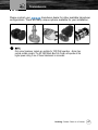
www.cobra.com
MF 2500 FISH FINDER
Owner’s Manual
All rights reserved. No part of this publication may be reproduced or distributed in any form or by any means, or stored in a database or retrieval
system, without prior written permission of the publisher.
©2006 Cobra Electronics CorporationTM
©2006 Cobra® Electronics Europe Limited
6500 West Cortland Street, Chicago
Illinois 60707 USA
Dungar House, Northumberland Avenue, Dun Laoghaire
County Dublin, Ireland
Cobra®, NightWatch®, Nothing Comes Close to a Cobra® and the snake design are registered trademarks of Cobra Electronics Corporation, USA.
Cobra Electronics CorporationTM, CobraMarineTM and iASAPTM are trademarks of Cobra Electronics Corporation, USA.
(a051205)
Our Thanks to You and
Customer Assistance
Thank you for purchasing a CobraMarineTM MF 2500 Fish Finder.
Properly used, this product will give you many years of reliable
service.
How Your CobraMarineTM MF 2500 Fish Finder Works
The CobraMarineTM chartplotter combined with the sonar performance of the
CobraMarineTM MF 2500 Fish Finder is one of the most advanced marine
navigation system available. Please read this Owner’s Manual carefully to
learn the operation and installation features for your unit. Refer to your
chartplotter Owner’s Manual for all other software operating instructions.
CUSTOMER ASSISTANCE INFORMATION
Should you encounter any problems with this product, or not understand its
many features, please refer to this Owner’s Manual. If you require further
assistance after reading this Owner’s Manual, Cobra Electronics
CorporationTM offers the following customer assistance services:
For Assistance in the U.S.A
Automated Help Desk English only.
24 hours a day, 7 days a week 773-889-3087 (phone).
Customer Assistance Operators English and Spanish.
8:00 a.m. to 6:00 p.m. through Fri. (excepth holidays) 773-889-3087 (phone).
Questions English and Spanish.
Faxes can be received at 773-622-2269 (fax).
Technical Assistance
English only: www.cobra.com (on-line: Frequently Asked Questions).
English and Spanish: [email protected] (e-mail).
For Assistance Outside the U.S.A
Contact Your Local Dealer or Distributor. Please see www.cobra.com
for contact information.
2
Owner's Manual
Warnings and Cautions
WARNINGS AND CAUTIONS
Before using your CobraMarineTM MF 2500 Fish Finder please read these
general precautions and warnings.
Please read through this manual before the first operation. If you have any
questions, please contact the customer service or your local CobraMarineTM dealer
or distributor.
Extensive exposure to heat may result in damage to the MF 2500 Fish Finder.
Connection to the power source with reversed polarity will damage the MF 2500
Fish Finder severely. This damage is not covered by the warranty.
The MF 2500 Fish Finder contains dangerous high voltage circuits which only
experienced technicians MUST handle.
The MF 2500 Fish Finder is not built water proof. Please make sure to avoid water
intrusion into the unit. Water damage is not covered by the warranty.
Nothing Comes Close to a Cobra®
3
Included in This Package
ABOUT THIS OWNER’S MANUAL
Any menu operations in this Owner’s Manual are related to the CobraMarineTM
Series of chartplotters. Connecting this product enables all of the Fish Finder
menus and screens in the CobraMarineTM Series chartplotter.
WHAT IS IN THE BOX?
When the package containing the MF 2500 Fish Finder is first opened, please
check it for the following contents (if any parts are missing contact the dealer
the MF 2500 Fish Finder was purchased from):
CobraMarineTM MF 2500 Fish Finder (with Power Serial and optional
devices cables already connected)
Owner’s Manual
The transducer is not included with this unit and can be ordered from your
CobraMarineTM dealer.
4
Owner's Manual
Table of Contents
1.
MANUAL ORGANIZATION
1.1.
TABLE OF CONTENTS
INTRODUCTION
.................................................................................................................... 2
OUR THANKS TO YOU
.................................................................................................................... 2
CUSTOMER ASSISTANCE INFORMATION .................................................................................................. 2
WARNINGS AND CAUTIONS
.................................................................................................................... 3
ABOUT THIS OWNER’S MANUAL ................................................................................................................. 4
WHAT IS IN THE BOX?
.................................................................................................................... 4
1. MANUAL ORGANIZATION
1.1. TABLE OF CONTENTS
1.2. OVERVIEW
.................................................................................................................... 5
.................................................................................................................... 5
.................................................................................................................... 6
2. THE MF 2500 FISH FINDER
.................................................................................................................... 7
2.1. TECHNICAL SPECIFICATIONS ........................................................................................................... 7
2.2 DIMENSIONS
.................................................................................................................... 8
2.3 MOUNTING THE FISH FINDER ............................................................................................................ 8
2.3.1 Installation
.................................................................................................................... 9
2.3.2 Installing Optional Devices ....................................................................................................... 9
2.4 STATUS LED
.................................................................................................................... 9
2.5 EXTERNAL CONNECTIONS .............................................................................................................. 11
2.6 POWER SUPPLY WIRING DIAGRAM ................................................................................................ 12
2.7 CHARTPLOTTER CONNECTION DIAGRAM ..................................................................................... 13
3. TRANSDUCERS
.................................................................................................................. 14
4. FREQUENTLY ASKED QUESTIONS ........................................................................................................... 16
Nothing Comes Close to a Cobra®
5
Overview
1.2. OVERVIEW
The Fish Finder consists of a high power transmitter, sensitive receiver and a
transducer. The Fish Finder sends an electrical pulse to the transducer which
contains an element that converts the pulse into acoustic (sound) wave which
is sent through the water. As this wave travels from the transducer to the
bottom, it may strike fish, structures, thermoclines (temperature changes in
the water, etc.). When the wave strikes an object(s) a certain amount of the
wave is reflected back to the transducer depending on the composition and
shape of the object. When the reflected wave is returned to the transducer it is
converted into an voltage and is amplified by the receiver, processed and sent
to the display. The speed of sound in water is roughly 4800 ft./sec, so the
time lapse between the transmitted signal and the received echo can be
measured and the distance to the object determined.
6
Owner's Manual
Technical Specifications
2.
THE MF 2500 FISH FINDER
2.1. TECHNICAL SPECIFICATIONS
Display Colors
: 16 colors
Display Vertical Resolution
: up to 400 pixels (depending on
chartplotter screen resolution)
Power Requirements
: 10 - 35 Volt dc
Over Voltage protection
Reverse Polarity protection
Power Consumption - operating : 17W max
Power Consumption - stand by : 1.7W max
Operating Frequency
: Dual 50 and 200kHz
Output Power
: 500 or 1000W (4000 or 8000Wpp)
Depth Range
1KW/200kHz : 2.5 Ft (0.8m) to 1200Ft (365m)
1KW/50kHz : 5 Ft (1.6m) to 4000Ft (1219m)
500W/200kHz : 2.5 Ft (0.8m) to 700Ft (213m)
500W/50kHz : 5 Ft (1.6m) to 1500Ft (457m)
Status LED
External Buzzer
: 12VDC, 400mA
Speed Sensor
: if available on transducer
Temperature Sensor
: one channel TEMP1 (if available on
transducer), optional second channel
TEMP2
NMEA Output sentences
: Depth: $SDDPT, $SDDBT
Speed: $VWVHW
Trip Log: $VWVLW
Water Temperature: $YXMTW
TEMP2 Temperature: $YXXDR
Operating temperature range : 0C to +50C
Storage temperature range
: -20C to +70C
Weight
: 1 kg (2,20 LBS)
Water Proof Specification
: IP 54
Case Size
: 7.62" (193.30mm) x 6.87" (174.30mm) x
2.19" (55.50mm)
Nothing Comes Close to a Cobra®
7
Dimensions
2.2
DIMENSIONS
2.3
MOUNTING THE FISH FINDER
The MF 2500 Fish Finder should be preferabily mounted in a dry and well
ventilated location. Do not mount it where it will be submerged in liquids or
exposed to high temperature.
8
Owner's Manual
Mounting the Fish Finder
2.3.1
Installation
Picture showing actual example of the MF 2500 Fish Finder installation.
Fix the MF 2500 Fish Finder to the mounting location using the four screws
(holes diameter 4 mm), see previous picture.
Route the CHARTPLOTTER cable to the CobraMarineTM chartplotter.
Mount the transducer according to the instructions provided with it.
Connect the POWER cable to the battery. Please be advised that the MF
2500 Fish Finder when not operating will remain in Stand-By mode.
2.3.2
Installing Optional Devices
See the External Connection diagram in Par. 2.5.
2.4
STATUS LED
There are seven different LED behaviors, representing seven different
diagnostic conditions. These are described below.
1. BOOTLOADER
LED Behavior: OFF
The MF 2500 Fish Finder is running in the bootloader, or is not
powered on at all.
2. STANDALONE DST, NO TRANSDUCER MODE
LED Behavior: ON, steady
Nothing Comes Close to a Cobra®
9
Status LED
The MF 2500 Fish Finder is in Standalone DST (Depth, Speed,
Temperature) mode, but is not pinging because Transducer ID has not
detected a transducer. This condition will occur if there is no
communication with the chart plotter, and no transducer is connected.
3. STANDALONE DST
LED Behavior: 1 long flash every 2 seconds
The MF 2500 Fish Finder is in Standalone DST mode, and is pinging
normally. This condition will occur if a transducer is connected properly,
but there is no communication with the chart plotter. In Standalone DST
mode, the NMEA 0183 output produces standard NMEA Depth, Speed,
and Temperature sentences.
4. NORMAL FISH FINDER MODE
LED Behavior: 1 short flash every 2 seconds
The MF 2500 Fish Finder and the transducer are operating properly.
This is the normal behavior when everything is working.
5. WAITING FOR COMMAND
LED Behavior: 2 short flashes every 2 seconds
The MF 2500 Fish Finder is not pinging because it is waiting for a
command from the chart plotter.
6. LOW POWER MODE
LED Behaviour: 3 short flashes every 2 seconds
The MF 2500 Fish Finder has detected a transducer without trasducer
ID, but the "ignore" command has been selected on the chart plotter so
the unit is pinging at low power.
7. NO TRANSDUCER MODE
LED Behavior: 4 short flashes every 2 seconds:
The MF 2500 Fish Finder is not pinging because transducer ID has not
been detected a transducer and the "ignore" command has not been
selected on the chart plotter.
10
Owner's Manual
External Connections
2.5
EXTERNAL CONNECTIONS
Nothing Comes Close to a Cobra®
11
Power Supply Wiring Diagram
2.6
POWER SUPPLY WIRING DIAGRAM
We recommended the installation of a switch and a (5A) fuse in the positive
DC supply to the MF 2500 Fish Finder. The MF 2500 Fish Finder is active
sending the digital depth through the NMEA interface even when the power
(chartplotter) is turned off, thus the need for a switch.
In the example below you will notice the positive DC power connection is run
through a switch and a fuse before connecting it to the MF 2500 Fish Finder
and the chartplotter.
12
Owner's Manual
Chartplotter Connection Diagram
2.7
CHARTPLOTTER CONNECTION DIAGRAM
See the following picture to make the connection to the chartplotter:
Nothing Comes Close to a Cobra®
13
Transducers
3.
TRANSDUCERS
The transducer is a device that transmits and receives sound waves into the
water. The active component inside the transducer is commonly referred to as
an element but actually is a piezoelectric ceramic material.
CobraMarineTM sells 4 transducers for various applications. See the table
below
.
14
Owner's Manual
Transducers
Please contact your
transducer dealer for other available transducer
configurations. There are many unique options available for your installation:
Only some transducer models are suitable for 1000 Watt operation. Airmar has
several suitable models. The MF 2500 Black Box Fish Finder will operate at this
higher power rating if one of these transducers is connected.
Nothing Comes Close to a Cobra®
15
Frequently Asked Questions
4.
FREQUENTLY ASKED QUESTIONS
4.1
How can I disconnect the cables from the MF 2500 Fish Finder
in case I need to do so for the installation?
Open the MF 2500 Fish Finder box unscrewing the four screws (see the
following figure).
Once the screws are removed, pull out the panel and the Printed Circuit
Board (PCB). Unscrew the cables from the PCB.
Wire the cables as needed.
16
Owner's Manual
Frequently Asked Questions
Reconnect the cables to the PCB.
Push the panel towards the case (be sure to have well positioned the
rubber gasket). Close the MF 2500 Fish Finder box screwing the four
screws.
4.2
How can I set optimal operating parameters.
Optimal operating parameters can be set accordingly with the intended use of
the Fish Finder. To quickly set get optimal operational parameters for fishing it
is possible to select the FISH preset from the Fish Finder Setup menu, while
for cruising it is possible to select the CRUISE preset.
4.3
What are preset modes?
Preset modes are pre-defined settings of the Fish Finder operating
parameters. There are five preset. You can use them to quickly set the Fish
Finder in the most commonly used operating modes. These are:
CRUISE: sets the Fish Finder in full auto mode with the sensitivity settings
(GAIN OFFSET, NOISE level and STC) optimized for displaying at best
the bottom.
FISH: sets the Fish Finder in full auto mode with the sensitivity setting
optimized for target searching.
AUTORANGE: sets the autorange mode and the manual gain mode.
BOTTOM LOCK: sets the range mode to bottom lock and the manual gain
mode.
MANUAL: sets the range mode and the gain mode to manual.
Nothing Comes Close to a Cobra®
17
Frequently Asked Questions
4.4
How can I restore the Fish Finder default operating parameters?
Simply select the CRUISE or the FISH preset. This will restore optimal
operating parameters for either cruising or fishing.
4.5
I’m using the Fish Finder in manual mode, how can I set the
parameters for optimal operation.
Setting operating parameters for optimal operation depends upon
environment conditions, user preference and intended usage of the Fish
Finder (e.g. fishing or cruising). A good starting point is to select a full auto
preset such as CRUISE or FISH and then, after waiting a while to allow the
echogram displayed to stabilize around the auto calculated parameters,
switch to the MANUAL preset mode. At this point it will be possible to fine
tune the operating parameters by slightly changing the auto calculated
parameters.
4.6
Can I always leave the Fish Finder in Full Auto/(auto gain and
auto range) mode?
Yes, but note that the full auto mode suits the 90% of the cases, however in
extreme situations the auto modes may fail and thus it is necessary to switch
to the Manual mode.
4.7
What are extreme situations in which auto modes may fail?
When the bottom is very deep, at high boat speed, when the bottom is very
shallow (< 5 feets), when the water is full of materials in suspension, or bad
sea conditions.
4.8
What should I do if the auto modes fail?
Failure of auto modes can happen for various reasons. You can find a range
of possibilities below.
4.8.1
Auto-range fails in very shallow waters displaying a digital
depth readout deeper than the actual value. What should I do?
This usually happens if the STC is set to LONG or MID and the bottom is
shallow or SHORT if the bottom is very shallow causing the auto-range to
hook to the second or third echo from the bottom (since in shallow waters the
sound bounces more times back and forth the surface to the bottom). Try
18
Owner's Manual
Frequently Asked Questions
decreasing the STC value to SHORT in shallow waters or to switch it to VERY
SHORT or OFF.
4.8.2
Auto range fails, and the digital depth readout displays a
very shallow reading. What should I do?
This usually happens if the STC is off or is set to a low value causing disturbs
from surface clutter to be stronger than bottom echoes. Try increasing the
STC value. As general rule STC has to be set as in shallow waters and
LONG in depth waters.
4.8.3
Auto-range fails in very deep waters displaying a digital
very shallow depth readout. What should I do?
The Fish Finder capability to detect the bottom decreases as the bottom depth
increase. If the bottom composition is soft as mud, if the sea conditions are
bad, if there are thermoclines or the water is full of materials in suspension it
can further decrease thus causing the digital depth readout to fail. When this
happens the auto-range algorithm also fails. To recover from this situation it is
necessary to switch to manual range mode and to set the manual depth
mode. When manual depth mode is selected the algorithm that calculates the
digital depth readout searches for the bottom within the range manually
selected by the user. At this point it is necessary to increase manually the
range until the bottom becomes graphically visible. If the echoes from the
bottom are strong enought, the Fish Finder shall look to the bottom giving a
correct depth reading and shall be possible to return in auto range mode.
Please note that if one or more of the conditions that reduce the echoes from
the bottom listed above is true the bottom may be not visible at all, in this
situation a strong thermocline or surface clutter may be interpreted by the Fish
Finder as the bottom.
4.9
At a very shallow range upper half of the screen appears
almost completely filled by the surface clutter. How can I
eliminate it?
This is normal in shallow waters. To clean up the surface clutter without
degrading the digital depth readout algorithm functionality it is possible to set
the STC value to custom setting the STC lenght to the same size of the
surface clutter, and increasing the STC strenght until the image on the screen
cleans up. Please note that in very shallow waters it is usually better to switch
to manual gain mode to reduce gain fluctuation due to rapidly changing
bottom conditions.
Nothing Comes Close to a Cobra®
19
Frequently Asked Questions
4.10 Why do I never see fish in the range between 0 to 0.7 meters?
The minimum range of the fish finder is 0.7 meters. In this interval the Fish
Finder can detect neither the bottom nor any target.
4.11 How can I reduce the surface clutter?
You can act by: properly setting the STC as described at 6.12 and also by
increasing the NOISE LEVEL and reducing the GAIN or the GAIN OFFSET (if
you are in auto gain mode). However please note that a strong attenuation of
surface clutter may also reduce the capability to detect targets.
4.12
The Fish Finder is in auto gain mode but the picture display
too many small targets, what shall I do to reduce the screen
clutter?
Try increasing the NOISE LEVEL or decreasing the GAIN OFFSET.
4.13
In very shallow waters when the AUTO GAIN mode is selected
there are fluctuations in the bottom profile width and its color
representation. What should I do?
In very shallow waters the environment situation (bottom/water condition) vary
very quickly thus causing the auto gain algorithm to create oscillations while
trying to set optimal GAIN value for each situation. To avoid this it is advisable
to switch to MANUAL GAIN mode and fine tune the GAIN to a fixed setting.
4.14
In very deep waters even setting the GAIN to its maximum
value I cannot see the bottom what shall I do?
Try decreasing the NOISE LEVEL. If the bottom is still not visible, there is
nothing you can do, the bottom echo is simply too weak to be detected.
20
Owner's Manual
Index
INDEX
A
ASSISTANCE .................................... 2
C
Case Size .......................................... 7
CONNECTION DIAGRAM ............... 13
connection to chartplotter ................ 13
D
Depth Range ..................................... 7
DIMENSIONS .................................... 8
Display Colors ................................... 7
Display Vertical Resolution ............... 7
E
External Buzzer ................................. 7
EXTERNAL CONNECTIONS .......... 11
F
Fish Finder ........................................ 6
I
Installation ......................................... 9
L
LED .................................................... 9
N
NMEA Output sentences ................... 7
O
Operating Frequency ........................ 7
Operating temperature range ............ 7
Output Power ..................................... 7
Over Voltage protection .................... 7
OVERVIEW ....................................... 6
P
package ............................................. 4
Power Consumption .......................... 7
Power Requirements ......................... 7
POWER SUPPLY ............................ 12
Q
Questions ........................................ 16
R
Resolution .......................................... 7
Reverse Polarity protection ............... 7
S
Speed Sensor .................................... 7
STATUS LED ..................................... 9
Status LED ........................................ 7
Storage temperature range ............... 7
T
TECHNICAL SPECIFICATIONS ....... 7
Temperature Sensor ......................... 7
transducer ................................... 6, 15
W
warnings ............................................ 3
Water Proof Specification ................. 7
Weight ............................................... 7
Nothing Comes Close to a Cobra®
21