1
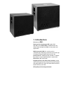
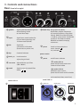
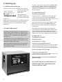
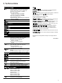
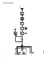
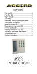
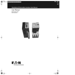
User Manual combi-SUB 12/15 preliminary 1 User manual ContentsPage 1. Introduction 3 2. Important safety instructions 4 3. Controls and connections 5 2 4. Starting up 4.1 Cabling and switching on 4.2 Level adjustment 6 6 6 5. Technical data 7 6. Block diagram 8 1. Introduction Welcome to B! Thank you for choosing an AER combi-SUB. AER offers two combi-SUBS 12 and 15 which are alike in their concept but differ in size, power and application. While the combi-SUB 12 is mainly used as subwoofer (low frequency extension) to an AER amp no matter if Compact 60, Domino or AP1 the combi-SUB 15 is additional well suitable as subwoofers to form a sound reenforcement system with AER AS 281. (Ref. info sheet) Rugged cabinets with heavy duty speakers, power amps with high dynamic range and a control section with adjustable cross-over and notch filter make the combi-SUB very versatile. AER quality and sound guaranteed. 2. Important Safety Instructions The following guidelines shall help minimize the risk of injury through fire or electric shock. C AU T I O N RISK OF ELECTRIC SHOCK DO NOT OPEN AT T E N T I O N RISQUE DE CHOC ELECTRIQUE NE PAS OUVRIR The lightning flash with the arrow head symbol within an equilateral triangle is intended to alert the user to the presence of unisolated ´dangerous voltage´ within this product´s enclosure that may be of sufficient magnitude to constitute a risk of electric shock to persons. 1. Carefully read these safety notes before you use the device! 2. Keep these safety notes in a safe place. 3. Pay attention to all warnings, instructions and additional texts on the unit. 4. This device was only designed for operation under normal climatic conditions (temperate climate). 5. Do not install or use your amp in close proximity to water or if you are wet yourself. 6. Do not subject your device to sudden and severe temperature changes. This could cause moisture condensation inside the unit, which could damage it. In the event of moisture condensation allow the device to dry out completely before use. 7. Use your amp in a safe place where nobody can step on cables or trip over and damage them. 8. Pay attention to an unhindered air circulation around the amp, never obstruct the air vents or grilles. 9. Always pull the mains plug before cleaning your amp or when left unused for a long period of time. Use only a dry cloth for cleaning. Avoid the use of detergents and do not let any liquids seep into the unit. 10. Use only the right fuses with the same current rating and trigger characteristic as replacements. Never mend fuses! Pull the mains plug before replacing a fuse. Should a fuse blow again after a short while, the device needs to be checked. 11. Never install your amp close to devices with strong electromagnetic fields such as large mains transformers, revolving machines, neon illumination etc. Do not lay signal cables parallel to power current cables. 12. There are no user-serviceable components inside the unit. To avoid the risk of an electric shock, the unit must not be opened. All maintenance, adjustment and repair works should be 4 The exclamation point within an equilateral triangle is intended to alert the user to the presence of important operating and maintenance (servicing) instructions in the literature accompanying this product. carried out by qualified staff only. Any unauthorized tampering will void the 2-year warranty. 13. In keeping with the EMV regulations screened cables with correctly fitted connectors must be used for all signal connections. 14. Always use an earthed power supply with the correct mains voltage. If you are in doubt about the power outlet ground, have it checked by a qualified technician. 15. Cable up your amp only when it is powered off. 16. This device should be installed near the socket outlet and disconnection of the device should be easily accessible. The mains plug of the power supply shall remain readily operable. Protect the power cord from being walked on or pinched particularly at plugs, convenience receptacles and the point where they exit from the apparatus. 17. This product may cause permanent hearing loss. Do not operate for long periods of time at a high volume level or at any level that is uncomfortable. If you experience any hearing loss or ringing in the ears, you should consult an audiologist. 18. The product should be located away from heat sources such as radiators, heat registers or other products that produce heat. 19. Do not place any open sources of fire, like candles, on the device. 20. Care should be taken so that objects do not fall onto the device and liquids are not spilled into the enclosure through openings. Ensure that no objects filled with liquids, such as vases, are placed on the device. 21. Do not place this device on an unstable cart, stand, tripod, bracket or table. The device may fall, causing serious injury to you and serious damage to the device itself. 3. Controls and connections Rear (from left to right) 2 2b 3 2c 4 2a 5 6 1 7 1 gnd lift Signal ground/protective ground disconnecting switch to avoid hum loops 2 input Signal input, combi socket, for 6.3 mm mono jack plugs and XLR connector (female) 2a link Signal link, symmetrical, XLR-socket (to connect any other unit) 2b clip Overload indicator 2c level (gain) Level control to adjust the gain level 3 crossover Adjustable low-pass-filter (100 - 300 Hz) 4 notch Switch to turn the notch-filter off/on 5 notch freq. Range from 50-300 Hz. Notch filter subjects frequencies of a certain frequency-range (here 50 and 300Hz) to severe reduction (-14 dB) in a very narrow bandwidth (quality 2). This helps to reduce feedback and other annoying resonances. 6 phase power section 7 power on/off-status indicator 8a combi-SUB 12: power on/off switch with mains socket and fuse holder 8b combi-SUB 15: powercon mains in/out , power on/off switch and fuse holder (ref. to technical data: mains fuse) combi-SUB 15 combi-SUB 12 8a Switch to invert the phase norm. (normal) inv (inverted) 8b mains in mains out power on fuse 5 4. Starting up 4.1 Cabling and switching on Connect your line-out or premaster-out signal of your source (amp, desk) to the input of the comb-SUB. The relevant specs and safety symbols are printed on the rear side of the unit. Make sure crossover position is at 100Hz (left turn), notch filter is in off position (button stands out) and phase switch is in normal position button stands out). 4.2 Level adjustment By setting the level correctly we mean the signal level in one or several devices in a signal chain is neither too high nor too low. This applies equally to all circuits in a complete circuit design (EQs, preamps etc.) Consequently, care must be taken that no part of the circuit is overloaded or that distortion is unintentionally added to the signal. We have carefully designed the circuit to achieve this objective whilst also providing controls for ’manual’ intervention. As soon as you raise the gain level the combi-SUB will be heard. It offers a wide range of features to enhance and define low-end and avoid feedback: ground-lift, adjustable crossover, notch-filter and phase-inversion. A) combi-SUB 12 and 15 as extension to an amp: A line-out signal is unfiltered and full range. This is why you can adjust the range the combi-SUB covers individually to adjust the amount of bass and midrange the combi-SUB should add. The phase switch inverts the signal phase by 180°. Make sure your amp and the combi-SUB are in phase, than you will hear the low frequencies full and strong. According to the overall volume you desire you may encounter resonance/feedback problems that can be actively addressed by making use of the Notch Filter. Witch it on and identify the resonance frequency by turning the frequency potentiometer. B) combi-Sub 15 as subwoofer to AS 281: Besides the above You may use a 2.1 setup: Two AS 281 plus one combi-SUB 15 - connect your left and right signal from your source (desk) to left and right AS 281 inputs and one AS 281 link out to feed the signal to the combi-SUB 15. In case you have a full 2.2 setup: Two AS 281 and 2 combi-Subs - connect left and right to the sub left and right and feed the signal through to the AS 281. Make use of phase, crossover and notch filter as explained above. As a small , easy-to-use PA solution it is ideal for small clubs, jazz and acoustic concerts and art events. 6 4. Technical data 5. Technical data Input connections input link clip indicator Electronically balanced line input Unbalanced jack connection also possible Combo socket, XLR + jack ¼” (6.35 mm) Nominal input voltage: 1 V (0 dBV) Min. input voltage: Combi Sub 12: 360 mV (–9 dBV) Combi Sub 15: 400 mV (–8 dBV) Max. input voltage: 9 V (+19 dBV) Input impedance: 20 k Equivalent input noise voltage (A-weighted): 6.5 µV (–104 dBV) XLR output, directly connected to input Headroom 6 dB Active crossover Filter type Crossover frequency Butterworth lowpass, 12 dB/oct. Adjustable, 70 – 200 Hz Notch filter Notch frequency Notch attenuation Bandwidth Notes Adjustable, 50 – 300 Hz -14 dB 0.7 octaves between –6.5 dB points Switchable Power Power amp Mains power Mains fuse Combi Sub 12: 200 W / 8 (1% THD) Combi Sub 15: 250 W / 8 (1% THD) Discrete bipolar transistor output Residual noise (A-weighted): 260 µV (–72 dBV) Dynamic range (A-weighted): 104 dB Mains voltage (depending on model): 100, 120, 230, or 240 V AC, 50–60 Hz Power consumption: Combi Sub 12: max. 500 W Combi Sub 15: max. 600 W Size: 5 x 20 mm Rating: For 230 and 240 V models: T 3.15 A L / 250 V For 100 and 120 V models: T 6.3 A L / 250 V NOTES Rated conditions: Input signal: 100 Hz sine, nominal input voltage applied Crossover (frequency) control fully clockwise. Notch filter off. Level adjusted such that the rated output power is obtained if the limiter is disabled (Level in center position approximately). Signal voltages stated as RMS values. 0 dBV corresponds to 1 V RMS. Min. input voltage: Input voltage required for rated output power (without limiter) with level fully clockwise Max. input voltage: Input voltage that does not cause more than 1% THD+N, suitable control settings provided THD + N: Total harmonic distortion + noise, with input and output levels 10 dB below rated conditions. Equivalent input noise voltage: Noise voltage at speaker output divided by gain of amplifier at 100 Hz. Control settings as stated under rated conditions. Measurement range: 20 Hz – 20 kHz. Input shorted. Residual noise: Output noise when the level control is set to minimum. Dynamic range: Ratio of nominal output voltage to residual noise voltage Specifications and appearance subject to change without notice. TD20130827 General Distortion (electrical) Signal processing Limiter threshold Speaker system Cabinet Finish THD + N < 0.1 % at 25 W / 8 Subsonic filter, RMS limiter Combi Sub 12: 160 W / 8 Combi Sub 15: 220 W / 8 Combi Sub 12: 300 mm (12”) woofer Combi Sub 15: 380 mm (15”) woofer Bass reflex enclosure 18 mm (0.71“) birch plywood M20 thread for speaker stand on top side Waterbased acrylic, black spatter finish Dimensions and weight Dimensions Weight Combi Sub 12: 430 mm (16,92“) high 490 mm (19,29“) wide 350 mm (13,77“) deep Combi Sub 15: 490 mm (19.29“) high 560 mm (22.05“) wide 440 mm (17.32“) deep Combi Sub 12: 19,55 kg (43,1 lbs) Combi Sub 15: 29 kg (64 lbs) 7 LINK 1 2 3 1 2 R T GAIN CROSSOVER FREQ. 3 CLIP NOTCH CLIP DETECTION OFF/ON 8 FREQ. INPUT SUBSONIC LIMITER POWER AMP B130827_130827 SPEAKER 6. Block diagram www.aer-amps.com 02092013 20131007 9