1
GNINRAW
Read this manual carefully
before operating this boat.
WARNING
The engine exhaust from this product
contains chemicals known to the State
of California to cause cancer, birth
defects or other reproductive harm.
YAMAHA
LIT-CALIF-65-01
Read this manual carefully before operating this boat.
This manual should stay with the boat if sold.
TO THE OWNER
Thank you for choosing a Yamaha Boat.
This Owner’s Manual contains information you will need for proper operation,
maintenance, and care. A thorough
understanding of these simple instructions will help you to obtain maximum
enjoyment from your new Yamaha.
If you have any questions about the
operation or maintenance of your boat,
please consult a Yamaha dealer.
Because Yamaha has a policy of
continuing
product
improvement,
this product may not be exactly as
described in this Owner’s Manual.
Specifications are subject to change
without notice.
This manual should be considered a
permanent part of this boat and should
remain with it even if the boat is subsequently sold.
IMPORTANT MANUAL INFORMATION:
In this manual, information of particular
importance is distinguished in the following ways:
This is the Safety Alert Symbol.
It is used to alert you of potential
personal injury hazards. Obey
all safety messages that follow
this symbol to avoid possible
injury or death.
WARNING
Failure to follow WARNING instructions could result in severe injury or
death.
NOTICE:
A NOTICE indicates special precautions that must be taken to avoid
damage to the boat or other property.
TIP:
A TIP provides key information to make
procedures easier or clearer.
AR240 HO, SX240 HO, 242 Limited S, 242 Limited
(STX1800 A-J/ AL-J/ B-J/ BL-J/ C-J/ C-LJ,
STX1800 D-J/ DL-J/ E-J/ EL-J/ F-J/ FL-J,
STX1800 G-J/ GL-J, STX1800 H-J/ HL-J)
Owner’s / operator’s MANUAL
©2009 by Yamaha Motor Corporation, U.S.A.
1st Edition, August 2009
All rights reserved. Any reprinting
or unauthorized use
without the written permission of
Yamaha Motor Corporation,
U.S.A. is expressly prohibited.
Printed in U.S.A.
LIT-18626-08-69
09-0112
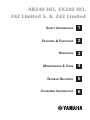
AR240 HO, SX240 HO,
242 Limited S, & 242 Limited
Safety Information
1
Features & Functions
2
Operation
3
Maintenance & Care
4
Trouble Recovery
5
Consumer Information
6
Chapter 1
SAFETY INFORMATION
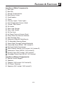
IDENTIFICATION NUMBER RECORDS . . . . . . . . . . . . . . . . . . . .
Primary I.D. Number . . . . . . . . . . . . . . . . . . . . . . . . . . . . .
Hull Identification Number (H.I.N.) . . . . . . . . . . . . . . . . . . . . .
Engine Serial Number . . . . . . . . . . . . . . . . . . . . . . . . . . . .
Star Labels . . . . . . . . . . . . . . . . . . . . . . . . . . . . . . . . .
Emission Control Information . . . . . . . . . . . . . . . . . . . . . . . 1-1
1-1
1-1
1-1
1-2
1-3
IMPORTANT LABELS . . . . . . . . . . . . . . . . . . . . . . . . . . . . . 1-4
Location . . . . . . . . . . . . . . . . . . . . . . . . . . . . . . . . . . . 1-4
Warning Labels . . . . . . . . . . . . . . . . . . . . . . . . . . . . . . . 1-5
SAFETY INFORMATION . . . . . . . . . . . . . . . . . . . . . . . . . . . . 1-8
Limitations On Who May Operate the Boat . . . . . . . . . . . . . . . . . 1-8
Required Equipment . . . . . . . . . . . . . . . . . . . . . . . . . . . . 1-9
Additional Equipment Recommendations . . . . . . . . . . . . . . . . . . 1-9
Cruising Limitations . . . . . . . . . . . . . . . . . . . . . . . . . . . . 1-10
Operational Requirements . . . . . . . . . . . . . . . . . . . . . . . . . 1-11
Hazard Information . . . . . . . . . . . . . . . . . . . . . . . . . . . . 1-12
Boat Characteristics . . . . . . . . . . . . . . . . . . . . . . . . . . . . 1-12
Night Operation . . . . . . . . . . . . . . . . . . . . . . . . . . . . . . 1-13
Water-Skiing . . . . . . . . . . . . . . . . . . . . . . . . . . . . . . . . 1-14
Rules OF THE ROAD . . . . . . . . . . . . . . . . . . . . . . . . . . . . 1-15
Steering and Sailing Rules . . . . . . . . . . . . . . . . . . . . . . . . 1-15
Rules When Encountering Vessels . . . . . . . . . . . . . . . . . . . . 1-16
Other Special Situations . . . . . . . . . . . . . . . . . . . . . . . . . 1-17
Reading Buoys and Other Markers . . . . . . . . . . . . . . . . . . . . 1-19
TO GET MORE BOATING SAFETY INFORMATION . . . . . . . . . . . . . 1-20
Boating Education and Training . . . . . . . . . . . . . . . . . . . . . . 1-20
ENJOY YOUR BOAT RESPONSIBLY . . . . . . . . . . . . . . . . . . . . . 1-20
Safety Information
1
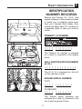
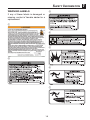
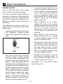
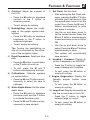
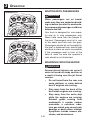
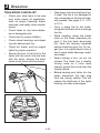
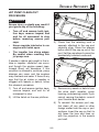
IDENTIFICATION
NUMBER RECORDS
Record your Primary I.D., H.I.N., and
engine numbers in the spaces provided
to assist you in ordering spare parts
from your Yamaha Boat dealer. Also
record and keep these I.D. numbers in
a separate place in case your boat is
stolen.
a
PRIMARY I.D. NUMBER
The Primary I.D. number is stamped
on a label attached to the engine
hatch.
b
HULL IDENTIFICATION NUMBER
(H.I.N.)
The H.I.N. is stamped into the hull
on the right rear corner.
c
ENGINE SERIAL NUMBER
PORT
STARBOARD
The Engine Serial Numbers are
stamped on a label attached to the
top of each engine’s oil tank.
1-1
1
Safety Information
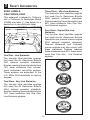
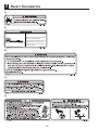
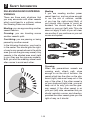
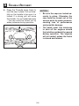
STAR LABELS
California Only
Three Stars - Ultra Low Emission
The three-star label identifies engines
that meet the Air Resources Board’s
2008 exhaust emission standards.
Engines meeting these standards have
65% lower emissions than One StarLow-Emission engines.
This watercraft is labeled in California
with a California Air Resources Board
(CARB) star label . See below for a
desciption of your particular label.
Four Stars - Super Ultra Low
Emission
The four-star label identifies engines
that meet the Air Resources Board’s
Sterndrive and Inboard marine engine
2009 exhaust emission standards.
Personal Watercraft and Outboard
marine engines may also comply with
these standards. Engines meeting
these standards have 90% lower emissions than One Star - Low Emission
engines.
a
One Star - Low Emission
The one-star label identifies engines
that meet the Air Resources Board’s
2001 exhaust emission standards.
Engines meeting these standards have
75% lower emissions than conventional carbureted two-stroke engines.
These engines are equivalent to the
U.S. EPA’s 2006 standards for marine
engines.
Two Stars - Very Low Emission
The two-star label identifies engines
that meet the Air Resources Board’s
2004 exhaust emission standards.
Engines meeting these standards have
20% lower emissions that One StarLow-Emission engines.
1-2
Safety Information
1
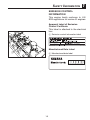
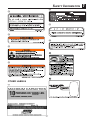
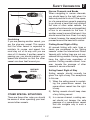
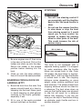
EMISSION CONTROL
INFORMATION
This engine family conforms to U.S.
EPA regulations for marine SI engines.
Approval Label of Emission
Control Certificate
This label is attached to the electrical
box.
Emission control information label
b
Manufactured Date Label
a
Manufactured date label
1-3
1
Safety Information
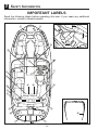
IMPORTANT LABELS
Read the following labels before operating this boat. If you need any additional
information, contact a Yamaha dealer.
b
1-4
Safety Information
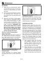
WARNING LABELS
If any of these labels is damaged or
missing, contact a Yamaha dealer for a
replacement.
1-5
1
1
Safety Information
Carbon monoxide (CO) can cause brain damage
or death.
Engine and generator exhaust contains odorless
and colorless carbon monoxide gas.
Carbon monoxide will be around the back of the
boat when engines or generators are running.
Move to fresh air if you feel nausea, headache,
dizziness, or drowsiness.
1-6
Safety Information
F2A
AR240 HO / 242 Limited S
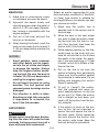
OTHER LABELS
1-7
1
1
Safety Information
SAFETY
INFORMATION
The safe use and operation of this
boat is dependent upon the use of
proper operating techniques, as
well as upon the common sense,
good judgment, and expertise of the
operator. Every operator should
know the following requirements
before operating the boat.
•
Before operating the boat, read
the Owner’s / Operator’s Manual,
the Operation Instruction Card,
and all warning and caution labels
on the boat. Also, watch the Basic
Orientation Video provided with
your boat. These materials should
give you an understanding of the
boat and its operation.
•
Never allow anyone to operate this
boat until they too have read the
Owner’s / Operator’s Manual, the
Operation Instruction Card, and
all warning and caution labels,
and if possible watched the Basic
Orientation Video. Showing them
the video may help reinforce the
information contained in these
materials.
Yamaha recommends a minimum
operator age of 16 years old.
•
Adults must supervise use by
minors.
Know the operator age and training requirements for your state. A
boating safety course is recommended and may be required in
your state. You can find local rules
by contacting the United States
Coast Guard (USCG), the National
Association of State Boating Law
Administrators, or your local Power
Squadron.
•
This boat is designed to carry the
operator, up to 9 passengers, and
cargo. Never exceed the maximum
load limit or allow more than 10
persons (or 9 persons if a water
skier is being pulled) to ride in the
boat at one time. Weight distribution affects performance. Keep
weight in the boat low and evenly
distributed from side-to-side and
front-to-back. Remove any unnecessary cargo and store it on shore.
Maximum Load: 1800 lb. (816 kg)
is the maximum total weight of
persons on board.
2200 lb. (998 kg) is the maximum
total weight of persons and cargo.
Limitations On Who May
Operate The BOAT
•
•
1-8
Safety Information
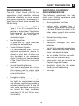
Required Equipment
Additional Equipment
Recommendations
The U.S. Coast Guard (USCG) has
regulations which describe minimum
standards of safety. You must comply
with these regulations, which apply to
boats like your boat which are less than
26 feet long.
•
1
The following equipment can help
make your boating experience safer
and more enjoyable:
Personal Flotation Devices (PFDs):
Type I, II, or III as required for all
people on board (see “Operational
Requirements” for more information), plus at least one Type IV
(throwable type).
•
Mooring fenders and lines.
•
Anchor with suitable line (a
“Danforth” type anchor and line that
is at least 6-times the depth of the
water where you will drop anchor
are recommended).
•
Manual-type bilge pump.
•
Fire Extinguisher:
At least two B-1 type hand-held
portable fire extinguishers.
•
First Aid kit.
•
Waterproof flashlight with extra
batteries.
•
Visual Distress Signals:
It is recommended that a USCGapproved pyrotechnic device be
stored on your boat. A mirror can
also be used as an emergency
signal. Contact your Yamaha dealer
or the Coast Guard for more information.
•
Tool kit with assorted screwdrivers,
pliers, wrenches (including metric
sizes), and electrical tape.
•
Oar or paddle (look for one with a
boat hook on the other end).
•
Spare parts, such as an extra set
of spark plugs and fuses.
Sound Signalling Device:
Your boat is equipped with a horn
that can be used to signal other
boats. See “Rules of the Road” for
more information.
•
Navigation charts for the waters
where you will be boating.
•
Tow rope.
•
•
Navigation Lights:
Your boat is equipped with navigation lights for use between sunset
and sunrise, and during periods of
reduced visibility, such as fog. Be
sure these lights are working and
are turned on when necessary
(see page 2-14 and 3-9 for more
information).
1-9
1
Safety Information
Cruising limitations
•
•
Do not operate the boat in rough
water, bad weather, or when visibility is poor; this may lead to an
accident causing injury or death.
Be alert to the possibility of bad
weather. Take note of weather forecasts and the prevailing weather
conditions before setting out in
your boat.
•
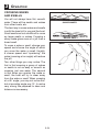
Never operate in water that is less
than 3 ft. (90 cm) deep, otherwise
you increase your chance of hitting
a submerged object, which could
result in injury.
Scan constantly for people, objects,
and other watercraft. Be alert for
conditions that limit your visibility
or block your vision of others.
•
Operate defensively at safe speeds
and keep a safe distance from people, objects, and other watercraft.
•
Do not follow directly behind other
boats.
•
Do not go near others to spray or
splash them with water.
•
Avoid sharp turns or other maneuvers that make it hard for others to
avoid you or understand where you
are going.
•
Avoid areas with submerged objects or shallow water.
•
Operate within your limits and avoid
aggressive maneuvers to reduce
the risk of loss of control, ejection,
and collision.
•
This is a high-performance boat –
not a toy. Sharp turns or jumping
waves or wakes can increase the
risk of back / spinal injury (paralysis),
facial injuries, and broken legs,
ankles, and other bones. Do not
jump waves or wakes.
3 FT (90 CM)
•
1-10
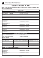
Leave a “float plan” with a responsible person on shore. Tell where
you plan to go and when you plan
to arrive, and provide a description
of your boat. Advise this person if
your plans change and also when
you arrive to prevent false alarms.
A sample float plan is included on
page 6-10.
Safety Information
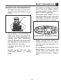
Operational Requirements
•
All riders must wear a Coast Guard
approved personal flotation device
(PFD).
•
For reasons of safety and proper
care of the boat, always perform
the pre-operation checks listed on
page 3-3 before operating.
•
Passengers must always sit in a
designated seating area, place feet
on the deck, and hold on to the hand
grips when the boat is in motion.
PFD
x
x
•
Eye protection is recommended to
keep wind, water, and glare from
the sun out of your eyes while you
operate your boat. Restraining
straps for eyewear are made which
are designed to float should your
eyewear fall into the water.
•
Footwear and gloves are recommended.
•
NEVER operate the boat after
consuming alcohol or taking
drugs.
1
x x x
x
x
x xx
SHOWN WITHOUT watersport TOWER
1-11
•
Always consult your doctor on
whether it is safe for you to ride in
this boat if you are pregnant or in
poor health.
•
Do not attempt to modify this boat.
Modifications to your boat may
reduce safety and reliability, and
render the boat unsafe or illegal to
use.
1
•
Safety Information
Attach the engine shut-off cord
(lanyard) to the PFD and keep it
free from the steering wheel or
other controls so that the engine
stops if the operator accidentally
leaves the helm. Failure to attach
the engine shut-off cord could
result in a runaway boat if the
operator is ejected.
•
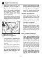
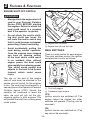
Hazard Information
After operation, remove the engine
shut-off cord and the keys to avoid
accidental starting or unauthorized
use by children or others.
c
•
Never start the engine or let it
run for any length of time in an
enclosed area. Exhaust fumes contain carbon monoxide, a colorless,
odorless gas that may cause death
within a short time. Always operate
the boat in an open area.
It is also important to have the
engines off when anyone is using
the extended swim step on models
equipped with one because of the
carbon monoxide in the exhaust
gases coming from underneath the
step.
a
b
BOAT CHARACTERISTICS
a Engine Shut-Off Switch
b Engine Shut-Off Cord with Clip
c Cord connected to PFD
•
Scan constantly for swimmers and
stay away from swimming areas.
Swimmers are hard to see and you
could accidentally hit someone in
the water.
•
Avoid being hit by another boat!
You should always take responsibility to watch for other traffic; other
boaters may not be watching for
you. If they do not see you, or you
maneuver more quickly than they
expect, you risk a collision.
Maintain a safe distance from other
boats or watercraft, and also watch
for boats’ ski ropes or fishing lines.
Obey the “Rules of the Road” (see
page 1-15), and be sure to check
behind you before making a turn.
•
1-12
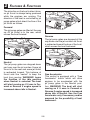
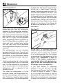
Jet thrust turns the boat. Moving the
throttle levers completely back to
idle or the Neutral position produces
only minimum thrust. If you are traveling at speeds above trolling, you
will have rapidly decreasing ability
to steer without throttle. You may still
have some turning ability immediately after moving the throttle levers
back to idle, but once the engines
slow down, the boat will no longer
respond to steering wheel input until
you apply throttle again or you reach
a trolling speed. Practice turning in
an open area without obstructions
until you have a good feel for the
maneuver.
Safety Information
•
•
This Yamaha Boat is water-jet
propelled. The pumps are directly
connected to the engines. This
means that the jet thrust will produce some movement whenever
the engines are running. The boat
has a “neutral” position, but since
the boat is always producing thrust
while the engines are running,
some forward or reverse movement may occur.
Do not use the reverse function
to slow down or stop the boat as
it could cause you to lose control,
be ejected, or impact the steering
wheel or other parts of the boat.
This could increase the risk of
serious injury. It could also damage
the shift mechanism.
•
Reverse can be used to slow
down or stop during slow speed
maneuvering, such as when docking. Once the engine is idling, shift
to reverse and gradually increase
engine speed. Make sure that there
are no obstacles or people behind
you before shifting into reverse.
•
Keep away from the intake grates
while the engine is on. Items such
as long hair, loose clothing, or PFD
(Personal Flotation Device) straps
can become entangled in moving
parts, resulting in severe injury or
drowning.
1
•
Stop the engines and remove the
clip from the engine shut-off switch
before removing any debris or
weeds, which may have collected
around the jet intakes.
•
Never insert any object into the
jet thrust nozzle while the engine
is running. Severe injury or death
could result from coming in contact
with the rotating parts of the jet
pump.
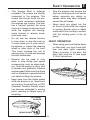
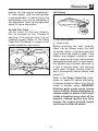
Night Operation
•
JET THRUST
NOZZLES
INTAKE GRATE
1-13
When using your boat before dawn
or after dusk, you must have both
bow and stern lights operating.
When at anchor in the dark, the
stern light must be lit. See page
2-14 for instructions.
1
Safety Information
WATER-SKIING
•
A second person should be on
board as a spotter to watch the skier;
in most states, it is required by law.
Let the skier direct the operator’s
control of speed and direction with
hand signals. Be sure the seat is
locked in place (pg. 2-16) before
getting underway.
•
When preparing to pull a skier,
operate the boat at the slowest
possible speed until the boat is well
away from the skier and slack in
the towrope is taken up. Make sure
that the rope is not looped around
anything.
After checking that the skier is
ready and that there is no traffic
or other obstacles, apply enough
throttle to raise the skier.
•
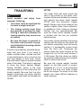
Make smooth, wide turns. The boat
is capable of very sharp turns,
which could exceed the abilities of
the skier. Keep the skier at least
50m (164 ft), about twice the distance of a standard towrope, away
from any potential hazard.
•
Be alert to the hazard of the towrope handle snapping back at
the boat when the skier falls or is
unable to get up on the skis.
You can use the boat to tow a water
skier, using the tow cleat provided.
It is the boat operator’s responsibility to
be alert to the safety of the water-skier
and others. Know and follow all state
and local water-skiing regulations in
effect for the waters in which you will be
operating.
The following are some important considerations for minimizing risks while
water-skiing.
•
•
The skier should wear an approved
PFD, preferably a brightly colored
one so boat operators can see the
skier.
The skier should wear protective
clothing. Severe internal injuries
can occur if water is forced into body
cavities as a result of falling into the
water or while reboarding. Normal
swimwear does not adequately protect against forceful water entry into
rectum or vagina. The skier should
wear a wetsuit bottom or clothing
that provides equivalent protection.
Such clothing includes thick, tightly
woven, sturdy, and snug fitting
apparel such as denim, but does not
include spandex or similar fabrics
like those used in bicycle shorts.
See pages 1-4, 1-7, and 2-22 for Watersports Tower use.
1-14
Safety Information
RULES OF THE ROAD
1
Steering and sailing rules
Whenever two vessels on the water
meet one another, one vessel has the
right-of-way; it is called the “stand-on”
vessel. The vessel that does not have
the right-of-way is called the “giveway” or “burdened” vessel. These rules
determine which vessel has the rightof-way, and what each vessel should
do.
Your Yamaha Boat is legally considered
a powerboat. Operation of the boat
must be in accordance with the rules
and regulations governing the waterway on which it is used.
Just as there are rules that apply when
you are driving on streets and highways, there are waterway rules that
apply when you are operating your
boat. These rules are used internationally, and are also enforced by the United
States Coast Guard and local agencies.
You should be aware of these rules,
and follow them whenever you encounter another vessel on the water.
Stand-On Vessel
The vessel with the right-of-way has the
duty to continue its course and speed,
except to avoid an immediate collision.
When you maintain your direction and
speed, the other vessel will be able to
determine how best to avoid you.
Several sets of rules prevail according to geographic location, but are all
basically the same as the International
Rules of the Road. The rules presented
here in this Owner’s / Operator’s Manual
are condensed, and have been provided
for your convenience only. Consult
your local U.S. Coast Guard Auxiliary
or Department of Motor Vehicles for
a complete set of rules governing the
waters in which you will be operating
your boat.
Give-Way Vessel
The vessel which does not have the
right-of-way has the duty to take positive and timely action to stay out of the
way of the stand-on vessel. Normally,
you should not cross in front of the
vessel with the right-of-way. You should
slow down or change directions briefly
and pass behind the other vessel. You
should always move in such a way that
the operator of the other vessel can
see what you are doing.
The General Prudential Rule regarding the right-of-way is that if a collision
appears unavoidable, neither boat has
the right-of-way. Both boats must avoid
the collision.
In other words, follow the standard
rules except when a collision will occur
unless both vessels try to avoid each
other. If that is the case, both vessels
become give-way vessels.
1-15
1
Safety Information
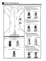
RULES WHEN ENCOUNTERING
VESSELS
Meeting
If you are meeting another power
vessel head on, and are close enough
to run the risk of collision, neither
of you has the right-of-way! Both of
you should alter course to avoid an
accident. You should keep the other
vessel on your port (left) side. This rule
does not apply if both of you will clear
one another if you continue on your set
course and speed.
There are three main situations that
you may encounter with other vessels
which could lead to a collision unless
the Steering Rules are followed:
Meeting: you are approaching another
vessel head-on.
Crossing: you are traveling across
another vessel’s path.
Overtaking: you are passing or being
passed by another vessel.
In the following illustration, your boat is
in the center. You should give the rightof-way to any vessels shown in the white
area (you are the give-way vessel). Any
vessels in the shaded area must yield
to you (they are the give-way vessels).
Both you and the meeting vessel must
alter course to avoid each other.
Crossing
When two power-driven vessels are
crossing each other’s path close
enough to run the risk of collision, the
vessel which has the other on the starboard (right) side must keep out of the
way of the other. If the other vessel is
on your starboard (right) side, you must
keep out of its way; you are the giveway vessel. If the other vessel is on
your port (left) side, remember that you
should maintain course and direction,
provided the other vessel gives you the
right-of-way, as it should.
1-16
Safety Information
1
Narrow Channels and Bends
When navigating in narrow channels,
you should keep to the right when it is
safe and practical to do so. If the operator of a power-driven vessel is preparing
to go around a bend that may obstruct
the view of other water vessels, the
operator should sound a prolonged blast
of four to six seconds on the horn. If
another vessel is around the bend, it too
should sound the horn. Even if no reply
is heard, however, the vessel should still
proceed around the bend with caution.
Overtaking
If you are passing another vessel, you
are the give-way vessel. This means
that the other vessel is expected to
maintain its course and speed. You
must stay out of its way until you are
clear of it. Likewise, if another vessel is
passing you, you should maintain your
speed and direction so that the other
vessel can steer itself around you.
Fishing Vessel Right-of-Way
All vessels fishing with nets, lines or
trawls are considered to be “fishing
vessels” under the International Rules.
Vessels with trolling lines are not considered fishing vessels. Fishing vessels
have the right-of-way regardless of
position. Fishing vessels cannot, however, impede the passage of other
vessels in narrow channels.
GIVE-WAY
GIVE-WAY
VESSEL
VESSEL
Sailing Vessel Right-of-Way
Sailing vessels should normally be
given the right-of-way. The exceptions
to this are:
1) When the sailing vessel is overtaking the power-driven vessel, the
power-driven vessel has the rightof-way.
2) Sailing vessels should keep clear
of any fishing vessel.
Other special situations
There are three other rules you should
be aware of when operating your boat
around other vessels.
3) In a narrow channel, a sailing vessel should not hamper the safe
passage of a power-driven vessel
that can navigate only in such a
channel.
1-17
Safety Information
“6”
C
H
A
M
IN
“7”
C “1”
A
N
L
NE
N “2”
L
NE
AN
CH
SE
CO
ND
AR
Y
1
RB “L”
or
RG “L”
“1” “3” “5” “7”
LIGHTED BUOY (Port Hand)
Odd number, increasing toward head
of navigation. Leave to port (left)
proceeding
White Light
Green Light
“5”
Old
“4”
New
“2” “4” “6”
LIGHTED BUOY (Starboard Hand)
Even number, increasing toward head of
navigation. Leave to starboard (right)
proceeding up-stream
“3”
White Light
Green Light
“A”
“2”
Old
“1”
New
“A”
LIGHTED SAFE WATER BUOY
No number. Marks midchannel, pass
on either side. Letter has no lateral
significance, used for identification and
location purpose
Top Mark
Green Light
White Light
Proceeding toward head of
navigation from seaward
SECONDARY CHANNEL BUOYS
STARTS NEW NUMBERING SYSTEMS
C “1”
CAN BUOY
Odd number. Leave to port.
or
Old
Old
New
New
RB “L”
RB “L”
LIGHTED PREFERRED
CHANNEL TO PORT BUOY
No number. Topmost band red –
preferred channel is to left of buoy.
Letter has no lateral significance, used
for identification and location purposes.
N “2”
NUN BUOY
Even number. Leave to starboard.
Red or
White Light
Red
Light
or
Old
No change
1-18
New
Safety Information
Reading Buoys and
Other Markers
The waters of the United States are
marked for safe navigation by the
lateral system of buoyage. Simply put,
buoys and markers have an arrangement of shapes, colors, numbers, and
lights to show which side of the buoy
a boater should pass on when navigating in a particular direction. The
markings on these buoys are oriented
from the perspective of being entered
from seaward (the boater is going
towards the harbor). Red buoys are
passed on your starboard (right) side
when proceeding from open water into
port, and black buoys are to your port
(left) side. An easy way to remember
the meaning of the colors is the phrase
“red right returning.” When navigating
out of the harbor, your position with
respect to the buoys should be
reversed; red buoys should be to port
and black buoys to starboard.
Many bodies of water used by boaters
are entirely within the boundaries of
a particular state. The Uniform State
Waterway Marking System has been
devised for these waters.
This system uses buoys and signs with
distinctive shapes and colors to show
regulatory or advisory information.
These markers are white with black
letters and orange borders. They signify
speed zones, restricted areas, danger
areas, and general information.
Remember, markings may vary by geographic location. Always consult local
boating authorities before riding your
boat in unfamiliar waters.
1-19
1
1
Safety Information
TO GET MORE
BOATING SAFETY
INFORMATION
The Online Boating Safety Course:
http://www.boatus.com/onlinecourse/
Be informed about boating safety.
Additional publications and information
can be obtained from many organizations, including the following.
United States Coast Guard
Consumer Affairs Staff (G-BC)
Office of Boating, Public, and
Consumer Affairs
US Coast Guard Headquarters
Washington, D.C. 20593-0001
ENJOY YOUR BOAT
RESPONSIBLY
You share the areas you enjoy when
operating your boat with others and
with nature. So your enjoyment includes
a responsibility to treat these other
people, and the lands, waters, and
wildlife with respect and courtesy.
Whenever and wherever you are
boating, think of yourself as the guest
of those around you. Remember, for
example, that the sound of your boat
may be music to you, but it could be
just noise to others. And the exciting
splash of your wake can make waves
others won't enjoy. Avoid riding close to
shoreline homes and waterfowl nesting
areas or other wildlife areas, and keep
a respectful distance from fishermen,
other boats, swimmers, and populated beaches. When travel in areas like
these is unavoidable, operate slowly
and obey all laws.
http://www.uscgboating.org
Other Sources:
You can find local rules by contacting
the National Association of State Boating
Law Administrators, or your local Power
Squadron.
boat education and training
The Online Boating Safety Course,
available through the watercraft section
of the yamaha-motor.com website, is
a free, 50-question learning course
available to the public. Upon successful completion of 80 percent or better,
the user can request a certificate of
completion by mail or can download
one immediately. The Online Boating
Safety Course, provided by the Boat/
US Foundation, is approved by the
National Association of State Boating
Law Administrators (NASBLA) and
recognized by the United States Coast
Guard. This course meets the education
requirement for those states that recognize non-proctored, NASBLA-approved
courses.
Remember that pollution can be harmful to the environment. Do not refuel or
add oil where a spill could cause damage to nature. Keep your surroundings
pleasant for the people and wildlife that
share the waterways: don't litter!
When you go boating responsibly, with
respect and courtesy for others, you
help ensure that our waterways stay
open for the enjoyment of a variety of
recreational opportunities.
1-20
Chapter 2
FEATURES & FUNCTIONS
LOCATION OF MAIN COMPONENTS . . . . . . . . . . . . . . . . . . . . 2-1
OPERATION OF CONTROLS AND OTHER FUNCTIONS . . . . . . . . . . 2-5
Steering . . . . . . . . . . . . . . . . . . . . . . . . . . . . . . . . . . 2-5
Tilt Lever . . . . . . . . . . . . . . . . . . . . . . . . . . . . . . . . . . 2-5
Engine Shut-Off Switch . . . . . . . . . . . . . . . . . . . . . . . . . . 2-6
Main Switches . . . . . . . . . . . . . . . . . . . . . . . . . . . . . . . 2-6
Throttle / Shift Levers . . . . . . . . . . . . . . . . . . . . . . . . . . . . 2-7
Fuel Tank Filler Cap . . . . . . . . . . . . . . . . . . . . . . . . . . . . 2-9
Gauges . . . . . . . . . . . . . . . . . . . . . . . . . . . . . . . . . . 2-9
Engine Overheat Warning System . . . . . . . . . . . . . . . . . . . . 2-13
Switches . . . . . . . . . . . . . . . . . . . . . . . . . . . . . . . . . . 2-14
Swivel Seat Operation . . . . . . . . . . . . . . . . . . . . . . . . . . . 2-17
Passenger Seats . . . . . . . . . . . . . . . . . . . . . . . . . . . . . 2-18
Stereo System . . . . . . . . . . . . . . . . . . . . . . . . . . . . . . . 2-19
Engine Hood . . . . . . . . . . . . . . . . . . . . . . . . . . . . . . . 2-19
Storage Compartments . . . . . . . . . . . . . . . . . . . . . . . . . . 2-20
Front Walk-Through . . . . . . . . . . . . . . . . . . . . . . . . . . . . 2-21
Rear Walk-Through . . . . . . . . . . . . . . . . . . . . . . . . . . . . 2-22
Swim Platform . . . . . . . . . . . . . . . . . . . . . . . . . . . . . . . 2-22
Swim Platform Shower . . . . . . . . . . . . . . . . . . . . . . . . . . 2-22
Watersports Tower . . . . . . . . . . . . . . . . . . . . . . . . . . . . 2-23
Features & Functions
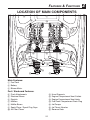
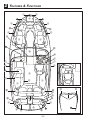
LOCATION OF MAIN COMPONENTS
b
Main Features:
a Fuel Tank
b Battery
c Blower Motor
Port / Starboard Features:
d Flush Attachments
e Electrical Boxes
f Dipstick
g Mufflers
h Muffler Boxes
i Spark Plugs / Spark Plug Caps
j Air Filter Cases
k Hood Supports
l Engine Compartment Vent Outlets
m Engine Compartment Vent Inlets
n Fuel Tank Compartment Drain Plug
Jet Pumps
Jet Thrust Nozzles
Reverse Gate
2-1
2
2
Features & Functions
2-2
Features & Functions
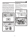
Location of Main Components:
a Bow Light
b Bow Eye
c Storage Compartments
d Bow Anchor Locker
e Grab Handles
f Cleats
g Courtesy Lights / Tower Lights
h Fuel Compartment Access Hatch
i Throttle / Shift Levers
j Ski Locker
k Stern Light Storage
l Stern Light Socket
m Ski Tow Hook
n Jet Pump Clean-out Access Panel
o Pump Clean-out Interlock Switches
p Rear Boarding Step
Accessory Pedestal Table Mounts
Tilt Adjustable Steering Wheel
Center Walk-Through Folding Windshield
Convertible Seat (AR240 / 242 Limited S)
Enclosed Head Compartment
Swim Platform Shower (242 Limited / 242 Limited S)
Watersports Tower (AR240 / 242 Limited S)
Docking Lights 242 Limited / 242 Limited S
Passenger Swivel Seat (SX240 / 242 Limited)
Location of Stereo Components:
Remote Control Keypad
Speakers
Tweeters (242 Limited / 242 Limited S)
CD Player / Receiver
Speakers (242 Limited / 242 Limited S)
2-3
2
2
Features & Functions
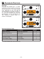
LOCATION of main components
20
2
1
3 4 5
6
7
8
0
M
T
30
40
10
50
0
60
2
1
3 4 5
M
6
7
8
0
T
+
1
2
3
4
5
6
E
+
-
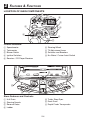
Control Features:
f Steering Wheel
g Tilt Adjustment Lever
h Switches and Breakers
i No-Wake / Cruise Assist Switch
a Speedometer
b Tachometer
c Blower Switch
d Ignition Switches
e Receiver / CD Player-Receiver
d
b
a
Stern Features and Controls:
b
e Trailer Strap Eyes
f Deck Drain
g Depth Finder Transponder
a Hull Drain
b Steering Nozzle
c Reverse Gates
d Ladder
2-4
Features & Functions
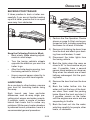
OPERATION OF
CONTROLS AND
OTHER FUNCTIONS
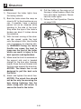
TILT LEVER
WARNING
•
Never touch the tilt lever during
operation, otherwise the steering
wheel could suddenly change
position, which may lead to an
accident.
•
Be sure the steering wheel is
locked in position after adjustment. If the steering wheel is not
locked in position, it may suddenly change position during
operation, which may lead to an
accident.
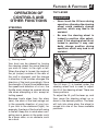
Steering
20
2
1
3 4 5
6
M
30
40
10
50
0
60
7
8
0
T
2
1
3 4 5
M
6
7
8
0
T
+
1
2
3
4
5
6
E
2
+
-
a Steering wheel
Your boat can be steered by turning
the steering wheel the same direction
you wish to travel, to the right or left.
When the wheel is turned, the angle of
the jet (output) nozzles at the rear of
the craft is changed, and the change
in direction of the nozzles changes the
direction of the boat accordingly. Since
the strength of the jet thrust determines
the speed and direction of a turn, the
throttle must always be opened above
idle when attempting a turn, except at
trolling speed.
a
The tilt lever a is located under the
steering wheel and is used to adjust
the tilt of the steering wheel. There are
three positions.
To adjust the tilt, pull the lever up, and
then move the steering wheel up or
down to the desired position. The lever
will lock into place when the wheel is
moved into one of the three available
positions.
Because boats steer from the stern
(rear), the stern of the boat swings out
in the opposite direction of your turn.
If you turn to the starboard (right), for
example, the stern of the boat will swing
to the left. Keep this in mind when navigating near a person in the water, such
as a down skier, or an obstacle, such
as a dock.
2-5
2
Features & Functions
Engine SHUT-OFF SWITCH
WARNING
•
•
•
Always attach the engine shut-off
cord to your Personal Flotation
Device (PFD) BEFORE starting
the engines. Failure to attach the
cord could result in a runaway
boat if the operator is ejected.
Do not attach the cord to clothing that could tear loose. Do
not route the cord in such a way
that it could become entangled,
preventing it from functioning.
a Engine shut-off switch
b Engine shut-off cord with clip
Avoid accidentally pulling the
cord during normal operation.
Once the engines have stopped
you have no steering control
of the boat which could result
in an accident. Also, without
engine power, the boat could
slow rapidly from planing speed.
This could cause people and
objects in the boat to be thrown
forward, which could cause
injury.
Main Switches
There is a main switch for each engine.
The main switches control the ignition
and electrical circuits as follows:
WARNING
Gasoline vapors can explode.
Operate blower for at least 4 minutes and
Check engine compartment bilge for
gasoline vapors before starting engines.
Do not start engines if there is a fuel leak
or loose electrical connection.
The clip on the end of the engine
shut-off cord must be attached to the
engine shut-off switch for the engines
to run. The cord must be attached to a
secure place on the Operator’s Personal
Flotation device (PFD). Should the
operator fall overboard or leave the
helm, the cord will pull out the clip,
stopping ignition to both engines. This
will prevent the boat from running away
under power.
a Port (left) engine
b Starboard (right) engine
OFF:
Ignition circuits are switched off. The
engine cannot be started but other
switches will operate. (The key can be
removed.)
ON:
Ignition circuits are switched on. (The
key cannot be removed.)
2-6
Features & Functions
START:
The starter motor will turn to start the
engine. (When the key is released, it
returns automatically to “ON.”)
TIP:
• The engine will not start when the
engine shut-off cord clip is removed
from the engine stop switch. The
starter motor will turn over without
the cord attached.
•
a Throttle / Shift Lever, port (left) side
engine
b Throttle / Shift Lever, starboard (right)
side engine
c Neutral
d Forward
e Reverse
f Free Accelerator Button
A separate lever for each engine
controls both throttle and shifting. In
normal operation, the levers are moved
together. Moving the levers forward
from Neutral shifts into the Forward
position and then, as the lever is
moved farther, accelerates the engines
for more thrust. Moving the levers back
from Neutral shifts into the Reverse
position and then, as the lever is moved
farther, accelerates the engines for
more thrust. The lever must be moved
about 35° from Neutral before Forward
or Reverse engages and the engine
starts to accelerate.
WARNING
•
When operating in Reverse, go
slowly. Do not open the throttle
more than half. Otherwise, the
boat may become unstable,
which could result in loss of
control and an accident.
•
Do not shift into Reverse while
traveling at planing speeds. Loss
of control, boat swamping, or
damage to the boat could occur.
THROTTLE / SHIFT LEVERS
Before shifting, make sure there
are no swimmers or obstacles in
the water near you.
The ignition switch will not operate (the starter motor will not turn
over) if the “Start” battery switch in
the battery compartment is turned
to the off position. See page 4-3 for
more information.
•
2
This boat is equipped with “start-ingear” protection. The engines will
not start unless the levers are in the
Neutral position.
The shift lever controls the direction of
travel.
2-7
2
Features & Functions
The drive line on the boat is direct drive,
so jet thrust is always being produced
while the engines are running. The
direction of the boat is controlled by jet
pump gates which direct the flow of the
jet thrust as follows:
Forward
The jet pump gates are lifted all the way
up. All jet thrust is to the rear, which
moves the boat forward.
Reverse
The jet pump gates are dropped all the
way down over the jet nozzles. Jet thrust
is redirected toward the bow of the boat,
which moves the boat backward.
Neutral
The jet pump gates are dropped down
part way over the jet nozzles. Some jet
thrust is to the rear and some jet thrust
is redirected forward. This balance of
thrust acts like “neutral” to keep the
boat from moving. WARNING! Leave
the throttles in the idle position
when Neutral is selected. The boat
will start moving as if it was in Forward or Reverse if engine speed is
increased above idle in Neutral.
Free Accelerator
This control is equipped with a “Free
Accelerator” button which will allow
engines to be accelerated with the
jet pump gates in the Neutral position. WARNING! The boat will start
moving as if it were in Forward or
Reverse if engine speed is increased
above idle in Neutral. Use the Free
Accelerator only if necessary and be
prepared for the possibility of boat
movement.
2-8
Features & Functions
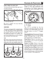
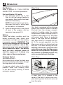
Fuel Tank Filler Cap
2
Both tachometer faces have an LCD
screen a. The right (starboard) side
tachometer is the “Master” gauge and
the left side (port) tachometer is the
“Slave” gauge.
To remove the fuel tank filler cap, turn it
counterclockwise.
20
2
1
3 4 5
10
7
8
0
a
M
T
a
b
a Fuel tank filler cap
0
6
c
Be sure to tighten the cap securely
before operating.
a LCD Screen
b "M" (Mode)
c "T" (Toggle)
GAUGES
The LCD is controlled by the two
buttons on the face of the lens. The left
b button is the “M” (Mode) button and
the right button c is the “T” (Toggle)
button.
The boat is equipped with a speedometer
a and two multi-function tachometers
b. The tachometer on the left is for the
port engine. The one on the right is for
the starboard engine. For cruising, adjust the throttle levers so both engines
are running at the same rpm.
Warning System: Warnings will display
automatically in the LCD of the master
gauge. Warnings may or may not be
accompanied by an audible alarm.
TIP:
Because of the mechanical throttle linkage, the throttle levers may not be exactly even with one another when the
engines are running at the same rpm.
Sleep Mode: Refers to the state when
both engines are off and the gauges
are shut down.
WARNING
Gasoline vapors can explode.
and
Operate blower for at least 4 minutes
for
Check engine compartment bilge
gasoline vapors before starting engines.
fuel leak
Do not start engines if there is a
or loose electrical connection.
Engine On Mode: Refers to the state
when the selected engine is ON and
the gauge of that engine is functioning.
a
b
b
20
2
1
3 4 5
6
7
8
0
30
Limited Functional Mode: Refers to the
state when one of the engines is OFF
and the gauge of that engine appears
not to be functioning. In this the gauge
is still running in the background.
40
10
50
0
60
2
1
3 4 5
6
HORN
7
8
0
NAV
ANCH
M
T
M
TOWER
LTS
T
SHOWER
2-9
DOCKING
LTD
CTLT/
TOWER
2
Features & Functions
Pushbutton Wake Up Mode: Refers to
the state when both engines are OFF,
the gauges are shut down, and the
operator pushes the “M” button to see
the clock. This mode only lasts for 5
seconds and then enters sleep mode
Displayable Data Include:
GPS Speed - Engine RPM - Fuel Level - Gallons Per Hour (GPH) - Gallons
Used - Voltage - Engine Hours - Water
Temp - Water Depth - Trip Odometer
- Latitude - Longitude - Heading (if
selected) - Compass (if selected) Elevation - Highest Speed - MPG Cruise Assist - Auxiliary Battery (if
installed) - Time (The clock can be
accessed when the engines are off by
momentarily pressing the M button.)
Power up and Basic Function: The
gauge system will power up upon engine start. A greeting will flash on the
screens, the gauge needles will sweep
and return to zero, the LCD will flash,
and the audible alarm will sound.
Master Gauge LCD (Starboard): During normal operation, the master gauge
LCD displays two lines of data (unless
in large font mode). Press the M button
to select a parameter. Each press of
the M or T button will display a different
parameter. To keep the parameter on
the line, simply do nothing and the
reverse video will disappear and the
parameter will remain. To change to the
other line on the display, press the M
and T buttons simultaneously when either line is highlighted. Scroll with the M
or T button separately.
Accessing the System Menu:
• To access and display information residing in the master gauge
press the M button for more than 3
seconds. Use the M or T button
separately to scroll.
•
To access a category, press and
release the M and T buttons
simultaneously.
•
To exit, simply do nothing and
the system will return back to the
original two-line display.
1) Set Units: Display information as
English or Metric.
2-10
• Press the T button to toggle
between English or Metric.
• To exit, press the M button or
simply do nothing.
Features & Functions
2) Contrast: Adjust the contrast of
the LCD.
• Press the M button to decrease
contrast or the T button to
increase contrast.
• To exit, simply do nothing.
7) Set Clock: Set the clock.
3) Backlighting: Adjust the brightness of the gauge system backlighting.
• Press the M button to decrease
brightness or the T button to
increase brightness.
• To exit, simply do nothing.
Tip: Turning the backlighting on
and off is controlled by the activation of the navigation lights.
4) Read Parameters: Read real time
data.
• Press the M button to scroll down
or the T button to scroll up.
• To exit, press the M and T
buttons simultaneously and wait.
• After entering the Set Clock submenu, pressing the M or T button
will allow you to set the hour. Use
the up and down arrow to set the
correct hour. Press the M and T
buttons simultaneously to save
and move to minutes.
• Use the up and down arrow to
set the correct minute. Press the
M and T buttons simultaneously
to save and move to set to AM or
PM.
• Use the up and down arrow to
select. Press the M and T buttons
simultaneously to save.
• The system will automatically
save and exit.
• Press the T button to toggle between Heading and Compass.
• To exit, press the M button or
simply do nothing.
9) Engine Diagnostics: Display the
Yamaha engine trouble code
(if any).
• Press the M and T buttons simultaneously to select the item to
calibrate:
6) Water Depth Alarm: Set the water
depth alarm.
8) Heading / Compass: Display direction in degrees or as N/S/E/W.
5) Calibrations: Calibrate systems
for customization.
2
• To exit, press the M button or
simply do nothing.
10) Large Font: Display information as
one line or two lines on the LCD.
• Press the M button to decrease
the alarm point and the T button
to increase the alarm point.
• Press the M and T buttons simultaneously to save and exit.
2-11
• Press the T button to toggle
between large or normal.
• To exit, press the M button or
simply do nothing.
2
Features & Functions
Warnings
Warnings are audible and / or visual
indicators of a fault condition. A warning
will be displayed on the master gauge
LCD. Warnings on the LCD can be
acknowledged by pressing the M button. Once acknowledged the message
will disappear and be replaced by an
“AL” flashing in reverse video in a
corner of the display.
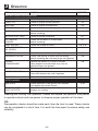
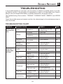
Warning Definition Table
Warning
LCD Display
Engine Overheating
Engine Over Temperature
Y
Engine Oil Pressure Low
Low Oil Press
Y
Check Engine
Check Engine
Y
Low Battery Voltage
Low Voltage
Y
High Battery Voltage
High Voltage
Y
Low Aux Battery Voltage *
Low Aux Battery
Y
High Aux Battery Voltage*
High Aux Battery
Y
* For models equipped with auxiliary battery only
2-12
Audible
Features & Functions
2
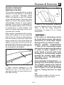
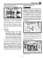
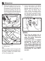
Engine Overheat
Warning system
This model is equipped with an engine
overheat warning system. If the engine
starts to overheat, “ENGINE OVER
TEMP” will appear on the LCD display
of the affected engine. The buzzer also
begins to sound. The engine speed is
automatically limited to help prevent
damage. If this occurs, immediately reduce the engine speed, return to shore
or maneuver to a safe location, and
check for water discharge at the cooling water pilot outlets.
If water is not circulating, something
may be clogging the jet intake grate.
Refer to the Jet Pump Clean-Out
procedures on page 5-5 for further
information.
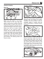
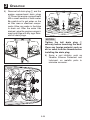
Each engine is equipped with coolingwater pilot outlets a on the starboard
side of the hull. The port side engine is
the one closest to the bow. Check that
water comes out of the outlet while the
engine is running, particularly while applying throttle. If you do not see any water at the outlet, cooling water may not
be circulating in the engine.
If the cause of overheating cannot
be found and corrected, take special
precautions to avoid major engine
damage while you return to shore.
SINGLE ENGINE OVERHEATING
— Shut off the overheating engine
and use the properly running engine
to return to shore. Operate at “no
wake” speed to prevent water from
flooding the non-operating engine
through the cooling water intake.
See page 2-15 for “No Wake Mode”
system operation.
BOTH ENGINES OVERHEATING — If
getting a tow from another vessel is
not possible, operate both engines
just slightly above idle while you return to shore. If you can be towed,
refer to “Towing the boat” on page
5-3.
Tip:
If water cooling passages on the
engines are dry, it will take about 20
seconds for water to reach the pilot outlets after starting.
TIP:
Press either the M or T button on the
tachometer to stop the buzzer.
2-13
2
Features & Functions
Engine Oil Pressure Low Warning
If the oil pressure does not rise to specification, “LOW OIL PRESS” will appear
on the tachometer of the affected engine
and the buzzer sounds intermittently.
At the same time, the engine speed is
limited to help prevent damage. If this
occurs, reduce the engine speed, return
to shore or maneuver to a safe location, and check the engine oil level (see
page 3-2 for engine oil level checking
procedures). If the oil level is low, add
enough engine oil to raise it to the proper
level. If the oil level is sufficient, have a
Yamaha dealer check the engine.
Check Engine Warning
If an engine sensor malfunction or
a short circuit is detected, “CHECK
ENGINE” will appear on the LCD of the
affected engine and the buzzer sounds
intermittently. If this occurs, reduce the
engine speed, return to shore, and have
a Yamaha dealer check the engine.
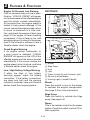
switcheS
WARNING
Gasoline vapors can explode.
Operate blower for at least 4 minutes and
Check engine compartment bilge for
gasoline vapors before starting engines.
Do not start engines if there is a fuel leak
or loose electrical connection.
NAV
ANCH
SHOWER
HORN
TOWER
LTS
DOCKING
LTD
CTLT/
TOWER
a Blower
b Bilge Pump
c Horn
d Light
e Tower (Limited S) and Courtesy Lights
f Shower (Limited Model)
g Docking Lights (Limited S Model)
Low / High Battery Voltage Warning
If either the High or Low battery
warnings appear, check the battery
connection. If the battery connections
are clean and tight and the warning
indication continues, have your Yamaha
dealer check the charging system.
Blower
Press this switch to turn on the blower
to ventilate the engine compartment.
See page 3-9 for more information.
Bilge Pump
Press this switch to activate the bilge
pump. See page 3-8.
Stereo
This is the master control for the stereo
system. Press this switch to allow CD or
radio operation.
2-14
Features & Functions
2
Courtesy Lights
Tower Lights (242 Limited S Model)
This toggle switch turns on lights
inside the boat. On the 242 Limited S
model, press the right side of the switch
to turn on both the courtesy lights and
the tower lights. Press the left side of the
switch to turn on the tower lights only.
Put the switch in the muddle position to
turn off all lights. NOTICE: Tower lights
are not for use as running lights.
Horn
Pressing this switch activates the horn.
The horn can be used to signal other
boats as required by the “Rules of the
Road” (see page 1-15).
TIP:
The helm switches will not work if the
battery switch in the battery compartment is turned to the off position. See
page 4-3 for more information.
Lights
This toggle switch controls the required
on-board lighting. Press the right side
of the switch to turn on both the bow
light and stern light for night running
("NAV"). Press the left side of the switch
to operate the stern light alone when
anchored at night ("ANCH"). Put the
switch in the middle position to turn off
all lights (see page 3-9).
Docking Lights
(242 Limited S Model)
This switch turns on the docking lights
located on both sides of the bow.
NOTICE: Docking lights are not for
use as running lights.
2-15
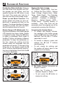
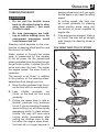
No Wake Mode
The No Wake Mode System is useful
for operating the boat at a steady speed
with a minimal wake. This is especially
convenient when traveling in harbors,
channels, or other areas posted with
low speed limits as “no wake zones.”
No Wake Mode can be engaged when
the throttles are at idle speed in Forward, Neutral, or Reverse. Three engine speed steps are available.
Features & Functions
To Set No Wake Mode:
Press the top, plus side, of the switch
once to set both engines in No Wake
Mode. A confirmation “No Wake 1”
will appear in the LCD screen. Engine
speed will initially be set at approximately 1600 rpm for very slow, no-wake
maneuvering. Pressing the plus side of
the switch again will increase engine
speed to approximately 1800 rpm (“No
Wake 2”) and another press will raise it
approximately 2100 rpm (No Wake 3”).
To decrease engine speed from No
Wake 2 or 3, press the bottom, minus
side, of the switch. From No Wake 1,
pressing the minus portion again will
cancel the No Wake Mode operation.
You may also cancel No Wake Mode
by moving the throttle levers above the
idle position.
NOWAKE
MODE
+
CRUISE
ASSIST
-
Cruise Assist Mode
The Cruise Assist feature is for steady
engine speed operation when the boat
is traveling above no wake speeds.
Cruise Assist Mode is available for
use whenever the engines are running
above 3000 and below 7000 rpm.
To Set Cruise Assist Mode:
Equalize the throttles before pressing
the Plus or Minus side of the switch
to set the initial speed. The indication “Cruise” will appear in the LCD
screen. Once set, a total of eight higher
(“Cruise +”) speeds and eight lower
(“Cruise –”) speed steps are available.
Pressing the switch on the top increases engine speed and pressing the bottom of the switch decreases engine
speed. Each step raises or lowers the
engines’ speed by approximately 150 to
200 rpm. To cancel Cruise Assist Mode
operation, move both throttle levers to
a lower engine speed below 3000 rpm
or shift into Neutral. The throttle levers
can be used at any time to increase or
decrease engine speed if desired.
For Operating Instructions Consult Owner’s Manual.
12V
Tip:
The engines must be running at idle
P
xil a
speed for at least 5 seconds
before
pressing the topside of the switch to
initiate No Wake Mode operation.
S
CP
M
ODU
PR
CTS
3 Au
yI
nput
2V
2
li
r
2-16
NOWAKE
MODE
CRUISE
ASSIST
+
-
For Operating Instructions Consult Owner’s Manual.
Features & Functions
SWIVEL SEAT OPERATION
Accessory Outlet
There is a 12VDC outlet with resettable
circuit breaker located in the portside
console storage compartment.
The driver’s seat is two-way adjustable. To move the seat forward or back,
pull up on the lever a located under
the front of the seat. Move the seat to
the desired position, then release the
lever.
NOTICE:
Do not use an automotive cigarette
lighter or other accessories that get
hot because the outlet can be damaged.
P3
yI
nput
12V
M
NOWAKE
MODE
CRUISE
ASSIST
r
Auxillia
To rotate the seat, first move the seat to
its fully forward position. Then, pull up
on the lever b located under the side
of the seat. Release the lever once you
begin to pivot. The seat will pivot freely
up to 180°, and will automatically lock
into the fully front-facing or rear-facing
position. There is also a friction lever c
to adjust how easily the seat rotates.
+
-
For Operating Instructions Consult Owner’s Manual.
The seat must always be locked into
the full front-facing position before getting underway. The seat bolster will flip
up for a raised seating position.
Switch Circuit Breakers
The electrical circuit for each switch
is protected by a circuit breaker. If the
button to the left of a switch pops out,
push it back in with your finger. If it pops
out again, ask your Yamaha dealer to
inspect the electrical system.
b
c
HORN
NAV
ANCH
TOWER
LTS
SHOWER
2
CTLT/
TOWER
DOCKING
LTD
LIMITED S MODEL SHOWN
TIP:
There is also an accessory fuse at the
battery (see page 4-14).
2-17
a
2
Features & Functions
Passenger seats
The passenger seat on the port side of
AR240 and 242 Limited S models can
be positioned in two ways. It can be positioned flat as a bench seat or upright.
To position the seat as a bench seat, lift
the latch on the underside of the seat.
Hold the seat by the straps provided
and pull the front of the seat forward
until it rests on the console lip.
SX240 and 242 Limited models are
equipped with a second swivel seat.
The controls are similar to the driver’s
swivel seat except it does not adjust
forward and back.
sx240 / 242 limited swivel seat
To position the seat with the upright
backrest, lift the strap provided at the
center of the seat and push the forward
end upright until it rests on the base.
Push down to latch the set in place
(see illustration directly above).
b
a
a Strap
b Latch
2-18
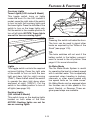
Two bow filler cushions are provided to
make a large flat area in the bow. One
of these cushions may also be used
as a backrest in the forward pass-thru
area.
Features & Functions
2
STEREO System
Engine Hood
A stereo receiver is standard. On AR240
and SX240 models, the system consists
of the Receiver / CD player, speakers,
MP3 input jack and a remote control
keypad at the stern. 242 Limited and
242 Limited S models have a Receiver
with built-in iPod® dock, speakers, MP3
input jack, handheld remote and a remote control keypad at the stern. Refer
to the stereo system Owner’s Manual
included with your boat.
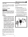
There is a hood latch located under
the front of the rear seat. To open the
engine hood, lift the latch hook upward
and lift the hood. The hood is supported
by gas-filled struts.
PW
BD/LD
V
T
MD
1 II
2INT
3RPT
4RDM
5
6
Hood Latch and Struts
MARINE
V
IEQ
T
AR240 AND SX240
A R CH
SE
BAND
2
ZONE
SUBW
OPEN
AS•PS
XBAS
TOP
+
SAT INFO
MENU
2 ZONE
AUDIO
ENTER
AQUATIC AV
1
2
4
3
AQ-IP-3B
RPT
5
MODE
-
6
MULTIENVIRONMENT
PLAYER
SHU
MODE
AQUATICAV
1
AUDIO
SEL
3
AUDIO
2
B
VOLUME
TRACK
2
1
4
BAND
T
A
SELECT
MENU
TOP
3
1
SEARCH
4
MENU
BAND
TOP
SEARCH
M
PWR
MODE
AQ-RF-3
242 LIMITED AND 242 LIMITED S
2-19
2
Features & Functions
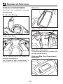
STORAGE COMPARTMENTS
Ski Locker
Your boat has convenient on-board
storage areas.
Bow Anchor Storage
Driver’s Side Console
Under Front Seats
Under Rear Side Seats
Pull up the seat cushions to access the
storage compartments.
Pull up the seat cushions to access the
storage compartments.
Starboard Side Rear Compartment
and Cooler
The starboard side compartment is
designed to be used as an ice chest.
2-20
Features & Functions
2
Port Gunwale Battery Compartment
WARNING
Do not carry any flammable substances in the battery compartment
or any heavy or metal items that can
damage the battery or cause a short
circuit. Sparks or fire could result.
There is a light in the compartment.
Press the light to turn it on. Press the
light again to turn it off. NOTICE: Be
sure the light is turned off when no
one is in the compartment. Leaving
the light on can drain the battery.
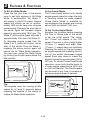
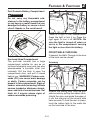
FRONT WALK-THROUGH
Enclosed Head Compartment
The port-side console has a large
compartment suitable for use as an
on-board changing room and can also
accommodate a portable toilet (not
included). Pull the latch to open the
compartment door, and pull it closed
behind you. WARNING! Carbon monoxide (CO) can cause brain damage
or death. Carbon monoxide can be
present in this compartment. Signs of
carbon monoxide poisoning include
nausea, headache, dizziness, drowsiness, and lack of consciousness. Get
fresh air if anyone shows signs of
carbon monoxide poisoning.
If desired, the Walk-Through to the bow
of the boat can be closed.
Doorway
Unlatch the folding door from the port
side console by pulling the rubber latch.
Unfold the door and guide the edge of
it into the channel on the driver’s side
helm console. To hold the door in place,
hook the rubber latch to the metal tab
on the front side of the door.
2-21
2
Features & Functions
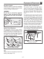
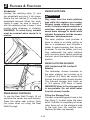
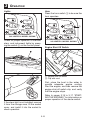
Windshield
Unsnap the retaining strap a from
the windshield and pivot it into place.
Rotate the two latches b to keep the
windshield secured. When the windshield is open, be sure to secure it
with the retaining strap to keep it from
moving while underway or trailering.
WARNING! To avoid injury, window
must be secured when vessel is in
motion.
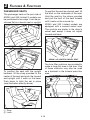
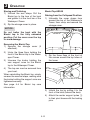
SWIM PLATFORM
WARNING
Stay away from the swim platform
area while the engines are running.
Exhaust gases coming from underneath it contain carbon monoxide, a
colorless, odorless gas which may
cause brain damage or death when
inhaled. Symptoms include nausea,
dizziness, and drowsiness.
The swim platform area provides a
place to stand or sit while putting on
skis or a wakeboard, and includes a
ladder to make boarding from the water easier. To use the ladder, pull it out
from underneath the swim platform
until it can drop down. Before operating
the boat, return the ladder to its storage
position.
a
SWIM PLATFORM SHOWER
(242 Limited and 242 Limited S
Models)
The freshwater shower mounted on
the swim platform can provide up to
1.4 gallons (5.3 liters) per minute flow
through the retractable shower handle.
The onboard storage tank holds up
to 10.0 gallons (37.8 liters) of water.
WARNING! Water in the storage tank
is non-potable. Do not drink water
from the shower handle.
b
b
Rear Walk-Through
To use the Rear Walk-Though, lift out
and stow the center rear seat cushion.
Press the center seat cushion firmly
into place when not using the Rear
Walk-Through.
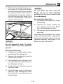
Filling the Storage Tank
Connect a standard garden hose to the
filler fitting a located under the stern
hatch. The tank is completely full when
water flows out on the starboard side
of the boat from the overflow vent.
Replace the filler cap securely.
2-22
Features & Functions
2
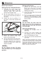
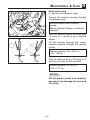
Watersports tower
(242 Limited and 242 Limited S
Models)
a
The Watersports Tower is provided as
an elevated tow point suitable for wakeboards and similar towable recreational
equipment. The center pylon can be
used to attach a standard ski rope or
other tow rope.
Using the Shower
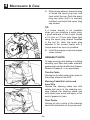
Press the pump switch on the instrument panel to the ON position. Lift the
handle b and push the flow control
lever. When finished showering, push
the pump switch to the OFF position.
Feed the shower handle hose back
into the opening and place the shower
handle in its cradle.
b
WARNING
Severe injury or death can result if
you ignore any of the following:
•
Maximum towing capacity:
1 Person, 350 lb. (158 kg) max.
•
Make sure tow rope is securely
fastened to the tow pylon on the
tower.
•
Do not tow a tube or other inflatable from the tower. Use the
transom tow cleat.
•
Stay clear of the tow rope while
pulling a wakeboard rider or skier.
•
Do not climb, hang, or sit on the
watersports tower.
NOTICE:
• Clean the shower handle and
hose with mild soap and water
only. Never use solvent-based
cleaners on the shower handle
or hose.
• Drain the storage tank to less
than half full if the boat is to be
stored or used in freezing weather.
Freezing water can damage the
tank.
NOTICE:
Do not modify the tower to tow
from any other point or to carry any
accessories or equipment not
approved by Yamaha. The tower
could be damaged.
2-23
Chapter 3
OPERATION
FUEL AND OIL . . . . . . . . . . . . . . . . . . . . . . . . . . . . . . . . .
Gasoline . . . . . . . . . . . . . . . . . . . . . . . . . . . . . . . . . . Engine Oil . . . . . . . . . . . . . . . . . . . . . . . . . . . . . . . . . Engine Oil Level . . . . . . . . . . . . . . . . . . . . . . . . . . . . . . 3-1
3-1
3-2
3-2
PRE-OPERATION CHECKS . . . . . . . . . . . . . . . . . . . . . . . . . . 3-3
Check List . . . . . . . . . . . . . . . . . . . . . . . . . . . . . . . . . 3-4
Check Points . . . . . . . . . . . . . . . . . . . . . . . . . . . . . . . . 3-5
OPERATION . . . . . . . . . . . . . . . . . . . . . . . . . . . . . . . . . .
Starting the Engines . . . . . . . . . . . . . . . . . . . . . . . . . . . .
Stopping the Engines . . . . . . . . . . . . . . . . . . . . . . . . . . .
Break-In Procedure . . . . . . . . . . . . . . . . . . . . . . . . . . . .
3-15
3-15
3-17
3-17
DRIVING YOUR BOAT . . . . . . . . . . . . . . . . . . . . . . . . . . . . 3-18
Getting to Know Your Boat . . . . . . . . . . . . . . . . . . . . . . . . . 3-18
Learning to Operate Your Boat . . . . . . . . . . . . . . . . . . . . . . 3-18
Turning the Boat . . . . . . . . . . . . . . . . . . . . . . . . . . . . . . 3-19
Boating with Passengers . . . . . . . . . . . . . . . . . . . . . . . . . 3-20
Boarding from the Water . . . . . . . . . . . . . . . . . . . . . . . . . 3-20
Boarding from a Dock or Landing Jetty . . . . . . . . . . . . . . . . . . 3-21
Stopping . . . . . . . . . . . . . . . . . . . . . . . . . . . . . . . . . . 3-21
Docking . . . . . . . . . . . . . . . . . . . . . . . . . . . . . . . . . . 3-22
Leaving a Dock . . . . . . . . . . . . . . . . . . . . . . . . . . . . . . 3-22
Beaching . . . . . . . . . . . . . . . . . . . . . . . . . . . . . . . . . 3-23
Anchoring . . . . . . . . . . . . . . . . . . . . . . . . . . . . . . . . . 3-23
Crossing Wakes and Swells . . . . . . . . . . . . . . . . . . . . . . . . 3-24
POST-OPERATION CHECKS . . . . . . . . . . . . . . . . . . . . . . . . . 3-25
TRAILERING . . . . . . . . . . . . . . . . . . . . . . . . . . . . . . . . .
Hitch . . . . . . . . . . . . . . . . . . . . . . . . . . . . . . . . . . . .
Trailering Checklist . . . . . . . . . . . . . . . . . . . . . . . . . . . .
Backing Your Trailer . . . . . . . . . . . . . . . . . . . . . . . . . . . .
Launching . . . . . . . . . . . . . . . . . . . . . . . . . . . . . . . . .
Loading . . . . . . . . . . . . . . . . . . . . . . . . . . . . . . . . . .
Lifting . . . . . . . . . . . . . . . . . . . . . . . . . . . . . . . . . . .
3-27
3-27
3-28
3-29
3-29
3-30
3-31
Operation
FUEL AND OIL
1) Before refueling, turn off the engines. Never refuel while smoking,
or while in the vicinity of sparks,
open flames, or other sources of
ignition.
Gasoline
WARNING
•
•
2) Refuel the boat in a well-ventilated
area. If the boat is in the water, be
sure it is securely moored to the
fueling dock. All passengers must
be out of the boat during refueling.
Gasoline and gasoline vapors
are extremely flammable. To avoid
fires and explosions and to
reduce the risk of injury when
refueling, follow these instructions.
3) Remove the fuel tank filler cap,
and then slowly add fuel to the fuel
tank. Stop filling when the fuel just
becomes visible in the bottom of
the filler tube. Do not “top off” the
tank, because gasoline could spill
out.
Gasoline is poisonous and can
cause injury or death. Handle
gasoline with care. Never siphon
gasoline by mouth. If you should
swallow some gasoline, inhale
a lot of gasoline vapor, or get
some gasoline in your eyes, see
your doctor immediately. If gasoline spills on your skin, wash
with soap and water. If gasoline
spills on your clothing, change
your clothes.
4) Wipe up any spilled fuel immediately.
5) Install the fuel tank filler cap. Make
sure that the fuel tank filler cap is
securely closed.
Recommended fuel:
Regular unleaded gasoline with a
minimum octane rating of 86
(Pump octane number) = (R + M)/2
90 (Research octane number)
Fuel tank capacity: 50 US gal (189 L)
NOTICE:
•
Do not use leaded gasoline.
Leaded gasoline can seriously
damage the engine.
•
Avoid getting water and contaminants in the fuel tank.
Contaminated fuel can cause
poor performance and engine
damage. Use only fresh gasoline
that has been stored in clean
containers.
3
Gasohol
There are two types of gasohol: gasohol
containing ethanol and that containing
methanol. Gasohol containing ethanol
can be used if ethanol content does
not exceed 10% and the fuel meets
minimum octane ratings. Gasohol containing methanol is not recommended
by Yamaha because it can cause fuel
system damage or engine performance
problems.
3-1
3
Operation
Engine oil level
Ring Free Fuel Additive
Gasoline is a precise blend of many different substances, each chosen to give
certain characteristics. Gasoline blends
have been changing in recent years in
response to concerns about pollution
and resulting emissions regulations.
One of the most obvious changes has
been the elimination of lead from fuels.
Check the engine oil level before each
use.
WARNING
Engine oil is extremely hot immediately after the engine is turned off.
Coming in contact with or getting
any engine oil on your clothes could
result in burns.
As gasoline has changed, the amount
of additives such as aromatics and
oxygenates has increased. These additives are important for the engines in
passenger cars, but they can have detrimental effects in marine engines.
NOTICE:
Make sure debris and water do not
enter the oil filler hole. Debris and
water in the engine oil can cause
serious engine damage.
While many additives available may
reduce deposits, Yamaha recommends
the use of Ring Free Fuel Additive,
available from your Yamaha dealer.
Ring Free has repeatedly proven its
ability to clean combustion deposits
from inside the engine, notably in the
critical piston-ring-land area, and fuel
system components. Follow product
labeling for use instructions.
To Check the Engine Oil Level:
1) Place the watercraft in a precisely
level position on land with the
engine stopped.
TIP:
If the engine was running, allow the
engine oil to settle by waiting 5 minutes
or more before checking the oil level.
Engine oil
2) Remove the dipstick, wipe it clean,
and then insert it back into the dipstick tube completely. Remove the
dipstick again and check that the
engine oil level is between the a minimum and b maximum level
marks.
Recommended Oil:
YAMALUBE 4W. If Yamalube 4W is not
available, use another 4-cycle oil that
meets the following specifications.
a
10W-30
10W-40
b
3-2
Operation
3
PRE-OPERATION
CHECKS
3) If the engine oil level is below
the minimum level mark, perform
steps 4~6 to add enough oil so the
oil level is between the minimum
and maximum level marks on the
dipstick. If the engine oil level is
significantly above the maximum
level mark, have a Yamaha dealer
service the watercraft.
CHECK LIST
Before operating this boat, perform
the checks in the following check list.
Always follow the inspection and maintenance procedures and schedules
described in this owner’s / operator’s
manual.
4) Remove the engine oil filler cap a.
WARNING
a
Failure to inspect or maintain the
boat properly increases the possibility of an accident or damage to
the watercraft. Do not operate the
watercraft if you find any problem.
a
If a problem cannot be corrected
by the procedures provided in this
manual, have the boat inspected by
a Yamaha dealer.
5) Pour engine oil into the filler hole.
Wait approximately 5 minutes until
the engine oil settles.
TIP:
The difference between the minimum
and maximum level marks on the dipstick is equal to approximately 1 quart
of engine oil.
6) Repeat steps 3~6 until the engine
oil is at the proper level.
7) Install the engine oil filler cap.
3-3
3
Operation
ITEM
CHECK
PAGE REF.
BEFORE LAUNCH OR OPERATION:
STEERING
Check for proper steering operation.
3-5
THROTTLE
Check for proper throttle operation.
3-5
SHIFTING
Check for proper shift operation.
3-5
FIRE EXTINGUISHER
Check readiness of the extinguishers.
3-6
HULL
Check the hull for damage or cracks
before launching.
ACCESS PORT CAPS
Check for proper installation.
3-7
JET (WATER)
INTAKES
Check that no debris is in the intakes
before launching.
3-7
FUEL SYSTEM
Check fuel system for leaks.
FUEL AND ENGINE
OIL LEVELS
Check fuel and oil level; add as necessary.
3-8
BATTERY
Check battery condition, mounting, and connection.
3-8
DRAINAGE SYSTEM
Check, and remove all water and fuel residue
before launching. Be sure drain plugs are tightened.
3-8
ENGINE
COMPARTMENT
Operate the blower for at least 4 minutes.
Open engine hood and check to be sure no
gasoline vapors are present.
3-9
ENGINE HOOD
Check that hood latch is secure.
2-19
LIGHTS AND HORN
Check lights to be sure they operate.
Press horn button to be sure it operates.
3-10
BIMINI TOP
Check that the top is secure.
3-8, 4-10
3-11 ~ 3-14
AFTER LAUNCH
SWITCHES
Check operation of the ignition start switches
and engine stop switch lanyard.
3-10
COOLING WATER
PILOT OUTLETS
Check that water comes out while the
engines are running.
3-11
Steering and Shifting Pre-Operation Checks will require two persons, one person
to operate controls and one person to observe proper operation at the stern.
TIP:
Pre-operation checks should be made each time the boat is used. These checks
can be completed in a short time. It is worth the time spent to ensure safety and
reliability.
3-4
Operation
CHECK POINTS
Steering
20
2
1
3 4 5
6
7
8
0
M
T
30
3
Throttle / Shifters
40
10
50
0
60
2
1
3 4 5
M
6
7
8
0
T
+
1
2
3
4
5
6
E
+
-
Move the control levers several times
through their full range of motion.
Operation should be smooth over the
complete range of motion and the
levers should return to Neutral without
hesitation.
Make sure the wheel is not loose.
There should not be any free play,
either in-and-out or in rotation. Turn the
steering wheel full-right and full-left to
make sure operation is smooth and unrestricted throughout the whole range.
Make sure both jet nozzles change
directions as the steering wheel is
turned. The jet nozzles should point
to starboard (right) when the wheel is
turned right. The jet nozzles should
point to port (left) when the wheel is
turned left. There should not be free
play between the steering wheel and
the jet nozzles.
Before launching, make sure both jet
pump gates drop down over the jet
nozzles to their stopper positions when
the control levers are moved to the
Reverse position. Also be sure both jet
pump gates return to the full-up stopper position when the levers are moved
to the Forward position.
3-5
3
Operation
Fire Extinguishers
located near the engine compartment
should be a “clean agent” type designed to displace oxygen, such as CO2
or other inert gasses or FE-36™, and
have a capacity of five pounds or more.
A chemical-type fire extinguisher may
not help when sprayed into the engine
compartment through the Fire-Port™
because that type needs to be aimed
directly at the base of the flames to
be effective. See below for Fire Port™
information.
Make sure two fire extinguishers are
aboard and full. See the instructions
supplied by the extinguisher manufacturers to determine indication of condition. As an inboard boat less than 26
feet in length, your boat must be fitted
with two B-1 type fire extinguishers
when navigating waters controlled by
the U.S. Coast Guard. In addition, most
state and local boating laws require
that the craft carry USCG-approved
fire extinguishers whenever the boat is
operated.
F
Fire Port™
ORT
E-P
IR
A Fire Port™ is mounted below the
center seat in the rear passenger area.
Use this port to spray the contents
of a fire extinguisher into the engine
compartment if a fire breaks out in the
engine area. WARNING! If there is
a fire in the engine compartment,
opening the hatch will add more oxygen to the fire, increasing the risk
of a larger fire or an explosion.
Fire extinguishers are not standard
equipment with this boat. If you do not
have them, contact your local Yamaha
Boat dealer or fire extinguisher dealer
for ones meeting the proper specifications.
One fire extinguisher is to be mounted
in the compartment in front of the driver
seat. The fire extinguisher recommended for this location is a chemical-type
extinguisher with a capacity of two
pounds or more.
If you see smoke or otherwise
suspect a fire, you can look through
the transparent flaps of the Fire Port™
to look for signs of flames. If there
is a fire, push the nozzle of the fire
extinguisher through the Fire Port™ and
follow the manufacturer’s instructions
to empty the contents of the fire extin-
The other fire extinguisher is to be
mounted inside the compartment under the rear passenger seat on the port
side. There is a location label outside
the compartment. This fire extinguisher
3-6
Operation
3
Jet Intakes
guisher into the engine compartment.
A “clean agent” type fire extinguisher
is recommended; a chemical-type fire
extinguisher may not be adequate in
this application. See Fire Extinguishers
above for more information.
a
Access Port Caps
Lift the hatch on the rear platform.
Pull up forcefully on the T-handle of
each cap. If the cap will move, it is not
installed properly Refer to “Jet Pump
Clean-Out Procedure” on page 5-5 for
proper installation instructions.
b
a Jet Thrust Intakes
b Intake Grates
Before launching the boat, carefully
check the jet intakes under the boat
for weeds, debris, or anything else that
might restrict the intake of water. If the
intakes are clogged, cavitation could
occur, reducing jet thrust, and possibly
damaging jet pump parts. In some cases,
the engine may overheat because of
a lack of cooling water, and damage
could result. Engine cooling water is
fed to the engine by the jet pumps (see
page 3-11).
Refer to Jet Pump Clean-Out procedures on page 5-5 before attempting
to remove weeds or debris from the jet
intake or impeller areas. WARNING!
Rotating parts could cause severe
injury or death. Before attempting to
remove weeds or debris from the jet
intake or impeller areas; shut off the
engines, remove ignition key, then
remove the engine shut-off switch
cord from the shut-off switch.
3-7
3
Operation
Fuel System
Refer to page 4-10, “FUEL SYSTEM
INSPECTION,” for correct procedure.
Bilge Pump –
Fuel and Engine Oil Levels
1) Turn the right switch key to ON.
Wait for the fuel gauge needle to
stop moving, then note the fuel level.
Add fuel if necessary.
NOTE: The fuel level is most accurate when the boat is sitting level
on the trailer or in the water.
Your boat is equipped with a drainage
system that channels water that enters
the boat from the storage compartments to the bilge under the engine
compartment. When the bilge pump is
turned on (see page 2-14), the pump
will sense when there is excessive
water in the bilge and will automatically drain most of it through the outlet a. For normal operation, turn the
bilge pump switch on during boat use
and turn it off when leaving the boat.
NOTICE: If the boat is to be left in the
water after use, leave the bilge pump
switch in the ON position. The pump
will activate if needed to drain any
water accumulating in the bilge.
2) Open the engine hatch, then check
oil level in the engines. Add as
necessary (see page 3-2).
Battery
Check the battery condition and the
battery electrolyte level. Make sure
connections are tight and that battery
is properly secured. WARNING! The
battery must always be fully charged
and in good condition. Loss of battery power may leave you stranded.
Never operate the boat if the battery
does not have sufficient power to
start the engine or if it shows any
other signs of decreased power.
Drain Plug –
Drainage System
Self-Bailing Deck—
Most water which enters the deck area
bails automatically out the stern through
the large drain hole in the deck.
A one-way check valve in the drain
prevents water from traveling back
to the deck during mooring or while
moving in reverse.
b
A drain plug b is located at the
center of the stern to allow more complete draining when the boat is removed
from the water.
3-8
Operation
Engine Compartment
Engine Compartment and
Fuel Compartment Drain Plug –
WARNING
c
X
X
X
3
Gasoline vapors can explode. Before
starting the engines, operate the
blower for at least 4 minutes and
check the engine compartment bilge
for gasoline vapors. Do not start
the engines if you can smell fuel
vapors in the engine compartment
or if there are any loose electrical
connections. Contact your dealer if
there is a problem you cannot locate
or correct.
X
Water will not normally enter the engine
compartment or fuel compartment
areas during operation. If it does, open
the drain plugs c and allow water to
drain. Also open the engine compartment plug when flushing the engine
area with fresh water after salt water
operation.
WARNING
Gasoline vapors can explode.
Operate blower for at least 4 minutes and
Check engine compartment bilge for
gasoline vapors before starting engines.
Do not start engines if there is a fuel leak
or loose electrical connection.
a
NOTICE:
•
•
Excessive water in the engine
compartment bilge can splash
into the air cleaner and engine.
This could cause engine damage.
Operate the bilge blower switch a for
at least 4 minutes before starting the
engines. Open engine hood and check
to be sure no gasoline vapors are
present. Check for fuel leaks or loose
electrical connections.
Be sure all drain plugs are tightened before operating your boat.
If a fuel or fuel / water mixture drains
from the fuel tank compartment drain
or is found in the engine compartment,
wipe it up immediately with dry rags.
WARNING! This indicates a fuel leak.
Do not operate the boat until the
source of the fuel leak is found and
corrected. Gasoline and its vapors
are highly flammable and explosive.
b
b Blower motor
3-9
3
Operation
Lights
Horn
Press the horn switch a to be sure the
horn operates.
HORN
NAV
ANCH
c
TOWER
LTS
CTLT/
TOWER
a
HORN
NAV
ANCH
SHOWER
TOWER
LTS
DOCKING
LTD
242 LIMITED S model shown
SHOWER
Check for proper operation of the bow,
stern, and instrument lights by pressing the switch c on the control panel.
CTLT/
TOWER
DOCKING
LTD
242 LIMITED S model shown
Engine Shut-Off Switch
a
b
a Engine shut-off switch
b Clip with cord
First, place the boat in the water to
provide adequate engine cooling.
Start the engine, and then remove the
engine shut-off switch clip, and verify
that the engine stops.
Refer to pages 3-15 to 3-17, “STARTING THE ENGINES,” for information on
proper operation of the starter switch.
If the stern light is not installed, remove
it from the storage area, lift the socket
cover, and install it into the socket to
check operation.
3-10
Operation
Cooling-Water Pilot Outlets
Check that water comes out from the
pilot outlets while engine is running
in the water. Refer to page 2-13 for
correct operation of the device.
3
Bimini Top SX240 and 242 Limited
Raising from the Collapsed Position:
1) Unzip and remove the storage cover.
2) Unfold the top by pulling it to
the back of the boat (toward the
stern).
3) Attach the snap hooks to the strap
eyes.
NOTE: It may take up to 20 seconds
for water to reach the pilot outlets when
first launching the boat. The amount
and force of the exiting water will vary
with engine rpm.
4) The top should be snug and wrinkle free. If the top is too loose, or
too tight, adjust the rear straps by
sliding the buckle up or down the
strap as needed.
NOTICE:
A continuous flow of water from the
pilot hole shows that water is flowing through the engine cooling passages. If water is not flowing out of
the pilot hole during operation, do
not continue to run the engines.
Overheating and serious damage
could occur. See Engine Overheat
Warning System, page 2-13, for more
information.
NOTICE:
Do not exceed 45 mph (72 km/h)
with the Bimini top in the deployed
position.
3-11
3
Operation
Storing and Trailering
1) Unhook the rear straps. Pull the
Bimini top to the bow of the boat
and gather it at the front bar of the
Watersport Tower.
Bimini Top AR240
Raising from the Collapsed Position:
1) Unbuckle the cover straps from
around the top of the Watersports
Tower, then unzip and remove the
storage cover.
2) Zip the storage cover in place.
NOTICE:
Do not trailer the boat with the
Bimini top in the fully extended
position. Put the cover over the top
to avoid damage.
Removing the Bimini Top
1) Remove the storage cover (if
attached).
2) Unzip the three flaps holding the
front of the Bimini top to the Watersport Tower.
2) Zip the three flaps at the front of
the canvas around the top tubes of
the tower.
3) Unscrew the knobs holding the
rear support arms for the Bimini
top to the Watersport Tower.
4) The top can now be removed from
your boat.
When reinstalling the Bimini top, simply
reverse the removal steps, making sure
the knobs holding the support arms are
tightened securely.
See page 4-4 for Bimini top care
information.
3) Unfold the top by pulling it to the
front of the boat (toward the bow).
4) Attach the center support poles a to their pivot bases with the locking
pins.
3-12
Operation
5) Attach the forward telescoping support poles b to their pivot bases
with the locking pins. Then, extend
the poles on both sides until the
locating buttons snap into place in
the first hole along the tubes. If the
top is not tight enough, extend the
tubes to the next hole.
3
NOTICE:
Do not trailer the boat with the
Bimini top in the fully extended
position. put the cover over the top
to avoid damage.
Removing the Bimini Top
1) Unbuckle the storage cover straps
(if attached).
2) Unscrew the knobs holding the
rear support arms for the Bimini
top to the Watersports Tower.
3) The top can now be removed from
your boat.
When reinstalling the Bimini top, simply
reverse the removal steps, making sure
the knobs holding the support arms are
tightened securely (see page 4-4 for
Bimini top care information).
NOTICE:
Do not exceed 45 mph (72 km/h)
with the Bimini top in the deployed
position.
Storing and Trailering
1) Collapse the forward support poles
and remove the locking pins.
2) Remove the locking pins from the
center support poles.
3) Pull the Bimini top to the rear of the
boat and gather it at the front bar of
the Watersports Tower.
4) Unzip the three flaps from around
the tower tubes
5) Zip the storage cover in place and
secure it to the Watersports Tower
by buckling the cover straps around
the top tubes.
3-13
3
Operation
Bimini Top Limited S
Storing and Trailering
1) Unhook the rear straps. Pull the
Bimini top to the bow of the boat
and gather it at the front bar of the
Watersports Tower.
Raising from the Collapsed Position:
1) Unbuckle the cover straps from
around the top tubes of the Watersports Tower, then unzip and
remove the storage cover.
2) Unzip the three flaps from around
the tower tubes
2) Zip the three flaps at the front of
the canvas around the top tubes of
the tower.
3) Zip the storage cover in place and
secure it to the Watersports Tower
by buckling the cover straps around
the top tubes.
3) Unfold the top by pulling it to
the back of the boat (toward the
stern).
NOTICE:
Do not trailer the boat with the
Bimini top in the fully extended position. Put the cover over the top to
avoid damage.
Removing the Bimini Top
1) Unbuckle the storage cover (if
attached).
2) Unscrew the knobs holding the
rear support arms for the Bimini
top to the Watersports Tower.
4) Attach the tension strap snap
hooks to the strap eyes.
3) The top can now be removed from
your boat.
5) The top should be snug and wrinkle free. If the top is too loose, or
too tight, adjust the rear straps by
sliding the buckle up or down the
strap as needed.
When reinstalling the Bimini top, simply
reverse the removal steps, making sure
the knobs holding the support arms are
tightened securely (see page 4-4 for
Bimini top care information).
NOTICE:
Do not exceed 45 mph (72 km/h)
with the Bimini top in the deployed
position.
3-14
Operation
3
OPERATION
Starting The Engines
WARNING
3 FT (90 CM)
SEVERE INJURY OR DEATH MAY
RESULT IF YOU IGNORE ANY OF
THE FOLLOWING:
•
•
Before operating your boat,
become familiar with all controls.
Consult your Yamaha dealer
about any control or function you
do not fully understand. Failure
to understand how the controls
work could cause an accident
or prevent you from avoiding an
accident.
Attach the engine shut-off switch
cord to your personal flotation
device before operating. Failure to
attach cord could result in a runaway boat if operator is ejected.
1) Always make sure the boat is
launched and used in waters that
are free from weeds and debris,
and at least 3 ft. (90 cm) deep.
WARNING! Never operate in
water that is less than 3 ft. (90
cm) deep. You increase your
chance of hitting an underwater
obstacle. You could be injured.
Pebbles or sand can also be
sucked into the jet (water) intake,
damaging the impeller.
NOTICE:
There is a hull drain plug at the bottom of the stern in the center. Be
sure it is securely tightened before
launching the boat.
3-15
3
Operation
2) Attach the engine shut-off cord to
your PFD. Install the cord clip onto
the engine shut-off switch by pushing the clip groove over the nut
beneath the knob. Be sure the cord
is not wrapped around the steering
wheel or tangled in the controls.
3) Put the control levers in the Neutral
position. The starter motor will not
operate unless the shift lever is in
Neutral. Turn the ignition key to
“Start.” When the engine starts,
release the key. If the engine does
not start after 5 seconds of cranking, release the key. Wait at least
15 seconds before trying to start
the engine again.
WARNING
Gasoline vapors can explode.
Operate blower for at least 4 minutes and
Check engine compartment bilge for
gasoline vapors before starting engines.
Do not start engines if there is a fuel leak
or loose electrical connection.
NOTICE:
•
Never turn the ignition key to
“Start” while the engine is running. The starter mechanism
could be damaged.
•
If the starter motor is engaged
continuously for more than 5
seconds, the battery will become quickly discharged and
it will be impossible to start the
engine. The starter motor may
also be damaged if it is engaged
continuously for more than 5
seconds.
a Engine shut-off switch
b Clip with cord
TIP:
It is not possible to start the engine with
the clip removed from the engine shutoff switch. However, the starter motor
will turn the engine over.
3-16
Operation
On this boat, the engines are connected
directly to the drive unit. Starting either
engine generates some thrust immediately. Only enough throttle should be
applied to keep the engine at a fast
enough idle to stay running.
3
Remove the ignition keys and the
engine stop switch lanyard if the boat
will be left unattended.
Stopping the engines immediately after
operating at high rpm is not recommended. Let the engines cool off at idle
or low speed for a few minutes first.
NOTICE:
Do not operate the boat with just
one engine running. Severe engine
damage could result because water
can flood the non-operating engine
through the cooling water intake. If
single-engine operation is unavoidable, operate the boat at a “no wake”
speed only.
WARNING
Gasoline vapors can explode.
Operate blower for at least 4 minutes and
Check engine compartment bilge for
gasoline vapors before starting engines.
Do not start engines if there is a fuel leak
or loose electrical connection.
STOPPING THE ENGINES
BREAK-IN PROCEDURE
The engine break-in period is essential
to allow the various components of the
engine to wear and polish themselves
to the correct operating clearances.
This ensures proper performance and
promotes longer component life.
1) Launch the boat and start the
engines (see page 3-15).
2) For the first 5 minutes, run the
engine at trolling speed. For the
30 minutes of operation after that,
keep the engine speed below 5,000
rpm. For the hour of operation after
that, keep the engine speed below
8,000 rpm.
3) Proceed with normal operation.
To stop the engine, return the throttle
levers to the idle position, then turn the
main switches to “Off.” The engines can
also be stopped by pulling the engine
stop switch lanyard. WARNING! Once
the engines have stopped, you have
NO STEERING CONTROL over the
boat. You could collide with another
boat, a dock, or other obstacle.
3-17
3
Operation
DRIVING
YOUR BOAT
Know and follow U.S. Coast Guard,
state, and local laws when operating
your boat.
Select a wide area to learn in, where
visibility is good and other boat traffic
is light. Keep the proper distance from
other boats and vehicles. Do not operate where people are swimming.
GETTING TO KNOW
YOUR BOAT
Operating your boat requires skills
acquired through practice over a period
of time. Take the time to learn the basic
techniques well before attempting more
difficult maneuvers.
Always attach the engine stop switch
lanyard to your personal flotation
device before operating.
Boating with your new boat can be a
very enjoyable activity, providing you
with hours of pleasure. But it is essential to familiarize yourself with the
operation of the boat to achieve the
skill necessary to enjoy boating safely.
Before operating this boat, read this
Owner’s Manual, the Operation Instruction Card, and all Warning and Caution
labels on the boat. Pay particular attention to the safety information in Chapter
1. This boat is designed to carry one
operator and up to nine passengers, as
long as the total weight of people does
not exceed 1800 lb. (816 kg). Never
have more than ten people in the boat.
LEARNING TO OPERATE
YOUR BOAT
Before boating, always perform the
Pre-Operation Checks listed on page
3-4. The short time spent checking the
machine’s condition will reward you
with added safety and a more reliable
boat.
You and all other passengers must
always wear a U.S. Coast Guardapproved personal flotation device
when riding in the boat. You should
consider wearing water shoes, eye
protection, gloves, and other protective
apparel. Water sports increase your risk
of injury from contact with your boat,
other vessels, docks, rocks, or coral.
A water-skier should wear protective
clothing. Severe internal injuries can
occur if water is forced into body cavities as a result of falling into the water
or while reboarding. Normal swimwear
does not adequately protect against
forceful water entry into rectum or
vagina. The skier should wear a wetsuit
bottom or clothing that provides equivalent protection. Such clothing includes
thick, tightly woven, sturdy, and snug
fitting apparel such as denim, but does
not include spandex or similar fabrics
like those used in bicycle shorts.
Grip the wheel firmly and keep both
feet on the deck when driving the boat.
3-18
Operation
TURNING THE BOAT
steering wheel input until you apply
throttle again or you reach a trolling
speed.
WARNING
•
Do not pull the throttle levers
back to idle when trying to steer
away from objects – you need
throttle to steer.
•
Be sure passengers are holding on before making turns. An
unprepared passenger could
lose balance and fall.
3
At trolling speed, the boat can
be turned gradually by steering
wheel position alone using just
the amount of thrust available at
engine idle.
D. If the engines are stopped, there is
no thrust. The boat will go straight
even though the steering wheel is
turned.
Steering control depends on the combination of steering wheel position and
the amount of throttle.
YOU NEED THROTTLE TO STEER.
A
Water sucked in through the intake
grate is pressurized by the impeller
in the jet pump. As the pressurized
water is expelled from the pump through
the jet thrust nozzle, it creates thrust to
move and steer the boat. The higher
the engine speed, the more thrust is
produced.
B
The amount of jet thrust, in addition
to the position of the steering wheel,
determines how sharply you turn.
A. More throttle produces high thrust,
so the boat will turn more sharply.
C
B. Less
throttle
produces
low
thrust, so the boat will turn more
gradually.
C. Pulling the levers back to idle or
Neutral produces only minimum
thrust. If you are traveling at speeds
above trolling, you will have rapidly
decreasing ability to steer without
throttle. You may still have some
turning ability immediately after
pulling the throttles back to idle,
but when the engine slows down,
the boat will no longer respond to
D
3-19
3
Operation
BOATING WITH PASSENGERS
TURNING LEFT
WARNING
20
2
1
3 4 5
6
30
40
10
50
0
60
7
8
0
M
2
1
3 4 5
M
When passengers are on board,
make sure they are seated and holding on before you start to accelerate.
An unprepared passenger could lose
balance and fall.
7
8
0
T
6
T
+
1
2
3
4
5
6
+
E
-
TURNING RIGHT
20
2
1
3 4 5
6
7
8
0
M
T
30
40
10
50
0
60
2
1
3 4 5
M
6
7
8
0
T
+
1
2
3
4
5
6
E
Your boat is designed for one operator and up to nine passengers only.
Never have more than ten people in
the boat. Passengers must sit in one
of the seats and hold onto the grips.
Passengers should sit so the weight in
the boat is balanced from side-to-side
and bow-to-stern as much as possible.
If the passenger seat in front of the
helm is used, be sure the operator’s
view ahead is not obstructed.
+
-
BOARDING FROM THE WATER
WARNING
Severe internal injuries can occur if
water is forced into body cavities as
a result of being near the jet thrust
nozzles.
•
Do not board from the rear, use
swim platform, or swim behind
boat if engines are running.
•
Stay away from the back of the
boat when engines are running.
•
Stay away from the swim step
while the engines are running.
Exhaust gases coming from
underneath it contain carbon
monoxide, a colorless, odorless gas which may cause brain
damage or death when inhaled.
Symptoms include nausea, dizziness, and drowsiness.
3-20
OperatiOn
peration
3
STOPPING
WARNING
•
You will lose steering control if
you completely pull the throttles
back to idle. You need throttle to
steer.
•
Do not use the reverse function
to slow down or stop the boat
from planing speed as it could
cause you to lose control, be
ejected, or impact the steering
wheel or other parts of the boat.
This could increase the risk of
serious injury.
346 ft (108.2
355
(105.5 m)
1) Be sure engines are off, then move
1)
to the stern of the boat. Pull out the
ladder and climb up onto the step.
Return the ladder to the stowed
position before climbing into the
boat.
2)
2) Climb up onto the swim platform,
then sit in one of the seats provided.
BOARDING FROM A DOCK OR
LANDING JETTY
1) Board the boat from the side. One
1)
person should board at a time by
stepping into the boat. Never jump
in. Avoid stepping on slick gelcoat
surfaces on the boat’s gunwales,
especially if wet.
2) Sit in one of the seats provided
2)
and put both feet on the deck.
The boat is not equipped with a
separate braking system. It is stopped
by water resistance after the throttle
levers are moved back to idle. From
full speed, the boat stops in approximately 355
346 ft. (108.2
(105.5 m) after the throttle
is moved back to idle. The stopping
distance varies depending on gross
weight, water surface conditions, and
wind direction. The stated straight-line
stopping distance should be used for
a reference. The boat slows down as
soon as the throttle levers are returned
to idle but will coast for a distance
before fully stopping. If you are not
sure you can stop in time before hitting
an obstacle, apply throttle and turn in
another direction.
3-21
3
Operation
DOCKING
WIND OR CURRENT
1) Make sure no obstructions, boats
or swimmers are close to the boat.
Come to a stop before you reach
the dock.
2) Notice how wind and water currents
are affecting boat movement as
you attach your mooring lines and
fenders.
3) Approach the dock at idle speed.
Use reverse as necessary during
slow speed maneuvering to help
control speed and direction. Position the boat according to wind and
water conditions. WARNING! Do
not use your hand, arm, or other
parts of your body to try to keep
the boat from hitting the dock.
You could be injured if the boat
pushes against the dock.
Wind or Current Pushing Boat
Away from Dock:
Slowly approach the dock at about a
45° angle. Secure the bow to the dock,
then use engine thrust or a boat hook
to gently move the stern to the dock.
No Wind or Current:
Approach the dock at a shallow angle.
Secure the bow to the dock, then use
engine thrust or a boat hook to gently
move the stern to the dock.
LEAVING A DOCK
Because boats steer from the stern,
the stern first moves in the direction opposite your desired turn. It is especially
important to understand this characteristic when leaving a dock. If you simply
turn the wheel to steer the bow away
from the dock, as you would when driving a car out of a parking space, you
will drive the stern of the boat into the
dock. The following steps are basic
maneuvering techniques which can be
used in most circumstances:
1) With engines idling and the bow
still moored to the dock, turn the
steering wheel toward the dock.
This will start to move the stern of
the boat away from the dock.
WIND OR CURRENT
Wind or Current Pushing Boat
Toward Dock:
Slowly maneuver to a shallow angle
and allow the boat to move toward the
dock.
2) When the stern is out a few feet,
release the bow mooring then steer
in the direction you want the bow to
move. Open the throttle slightly and
begin to move away from the dock.
3-22
Operation
BEACHING
1) Make sure no obstructions, boats
or swimmers are near the beach.
2) Approach the beach slowly and
stop the engines when the water is
about 3 ft. (90 cm) deep. Remember: turning is impossible with the
engine stopped.
3) Get out of the boat and pull the
bow up on the beach.
4) When leaving the beach, push the
boat out into water that is at least 3
ft. (90 cm) deep before starting the
engines.
NOTICE:
•
•
•
Small pebbles, sand, seaweed,
and other debris can be ingested into the jet intake and impair
or damage the impeller. Always
stop the engines before beaching the boat. Be sure the boat is
in water 3 ft. (90 cm) deep before
starting the engines again.
Do not beach the boat on rocky
beaches. The hull gelcoat and
exposed pump housings can be
damaged.
Pay attention to shifts in tides.
Beaching at high tide may make
it impossible to re-launch the
boat if the tide recedes.
ANCHORING
WARNING
Always anchor from the bow. Anchoring from the stern will make the boat
unsteady. A strong current can pull a
stern-anchored boat underwater.
3
Select an anchor appropriate for your
boat and water conditions. A “danforth”
(or fluke) type anchor is suitable for
most applications; your dealer can help
you choose an anchor.
1) Make sure the anchor line is
securely tied to the anchor and to
the bow eye.
2) Move the boat to the spot where
you want to lower the anchor, heading the boat into the wind or current. Stop the boat, then lower the
anchor until it hits bottom.
3) While keeping tension on the line,
slowly back up the boat until you
have let out line that is 4 to 6 times
the depth of the water. For example, if you are anchoring in 10 feet
of water, let out 40 to 60 feet of line.
Secure the line.
4) Pull on the line to be sure the
anchor is holding. Also, periodically
check your boat’s position against
the shoreline to make sure it is not
drifting and dragging the anchor.
Reset if necessary
5) To pull in (“weigh”) the anchor,
start the engines and move forward, keeping tension on the line
as you pull it in. When the anchor
line is straight up and down, pull
hard to lift the anchor from the bottom material.
6) If the anchor is stuck on the bottom, try this: Let out a few feet of
anchor line and secure the line to
the boat, again. Slowly maneuver
the boat around the anchor until
the anchor pulls loose. Keep the
line taut during this procedure.
3-23
3
Operation
CROSSING WAKES
AND SWELLS
You will not always have flat, smooth
water. There will be swells and wakes
from other boats, etc.
The best way to cross wakes and swells
is with the least jolt to you and the boat.
Small swells are not as difficult to cross
as larger swells or wakes. Crossing a
sharp wake gives more of a jolt than a
broad swell.
To cross a wake or swell, change your
speed and choose the angle at which
you cross the wake or swell. Usually,
a slower speed and “quartering” the
wake (crossing at an angle) will reduce
the jolt.
Two other things you may notice. The
first is that crossing a group of wakes
or swells is not as easy or smooth as
crossing just one wake. The second
is that when you quarter the wake or
swell, the boat will try to steer away
from the wake or swell. When crossing
at a 45° angle, you may not notice this,
but at a smaller angle, say 10°, it can be
very strong. Be prepared to steer and
balance as necessary.
3-24
SHARP WAKES
BROAD SWELL
WAKE
90°
45°
10°
Operation
POST-OPERATION
CHECKS
POST-OPERATION CHECKS
These post-operation procedures are
developed to help preserve the longterm appearance and reliability of your
boat. Perform these procedures as
soon as possible after the boat is loaded
back on the trailer after the day’s use.
Some owners prefer to moor their boat
seasonally, rather than keeping it on
the trailer between uses. Extended
mooring is not recommended. Proper
flushing of the cooling system on each
engine is not possible with the boat in
the water. In addition, conditions such
as stray electrical voltage in the water, marine organisms, and saltwater
corrosion can adversely affect the life
of many boat components. NOTICE:
Leaving the boat in the water for
extended periods will accelerate
the rate of normal deterioration of
the jet pump components, sacrificial anodes, hull finish and other
components.
3
1) After putting the boat on the trailer,
flush cooling system on each engine to prevent the cooling system
from clogging up with salt, sand, or
dirt. Refer to page 4-1 for the cooling system flushing procedure.
2) Drain residual water from the
exhaust system by starting the engine, then alternately pushing the
control lever up to half throttle and
back to idle for 10 to 15 seconds.
NOTICE: Never run the engine at
full throttle or for more than 15
seconds while the boat is out of
the water. The engine may overheat and / or seize.
3) Wash down the hull, helm, and both
jet drive units with fresh water.
4) Open the rear platform hatch, and
check for any water pooled on top
of the clean-out port caps. If water
is found, remove the caps, let water
drain, then reinstall the caps. See
Page 5-5 for more information.
If you do decide to moor your boat, be
sure to remove it from the water periodically to clean the hull and jet pump
area. The frequency of maintenance
required will depend upon whether the
water is salt or fresh and other local
water conditions.
3-25
3
Operation
5) Remove hull drain plug a and the
engine compartment drain plugs
b. Rinse the engine compartment
with a small amount of fresh water.
Be careful not to get water on the
air filter area or electrical components. Allow any water in the bilge
to drain out. After the water has
drained, wipe the engine compartment and bilge with dry rags. Reinstall all drain plugs.
NOTICE:
Tighten the hull drain plug a
securely before launching the boat.
Clean any foreign material, such as
dirt or sand, from the threads before
installing the drain plug.
a
6) Spray a rust inhibitor, such as
Yamaha Silicone Protectant and
Lubricant, on metallic parts to
minimize corrosion.
b
X
X
X
X
3-26
Operation
TRAILERING
3
HITCH
WARNING
Avoid accident and injury from
improper trailering:
•
The trailer must be matched for
the boat’s weight and hull.
•
The towing vehicle must have
the capacity of pulling the load.
Pulling a load that exceeds the
towing capacity may cause loss
of control.
•
Be sure the boat is secured to
the trailer and the trailer is properly hitched to the towing vehicle
before towing.
A trailer is provided as standard equipment with your boat. If you need to
obtain another trailer, choose one that
is manufactured to carry a boat of the
size and weight of your boat. Check
the certification label on the left forward
side of the trailer. This label is required
to show the Gross Vehicle Weight
Rating (GVWR), which is the load
carrying capacity of the trailer plus the
trailer’s weight. Be sure that the total
weight of your boat, any cargo, and the
trailer weight itself does not exceed the
GVWR.
The trailer hitch ball must match the
size of the socket on the trailer hitch
coupler. Hitches are divided into classes
that specify the gross trailer weight
(GTW) and the maximum tongue
weight. Always use a hitch rated for the
same or higher class. Use a bolted-on
or welded-on hitch; clamp-on bumper
hitches are not recommended. Be
sure the trailer hitch’s release handle
is latched with the lock pin installed
before towing.
Use safety chains between the towing
vehicle and the trailer so the trailer will
not detach completely from the towing
vehicle if it accidentally comes loose
from the hitch ball. Crisscross the
chains under the trailer tongue so the
tongue will not hit the road surface if
it falls loose. Rig the chains as tightly
as possible while allowing just enough
slack to permit tight turns.
Be sure the tongue weight (vertical
weight on the hitch point) is correct.
Generally, 5% to 10% of the combined
weight of the boat and trailer should
be on the tongue. Too much or too little
weight can cause difficult steering or
trailer swaying.
3-27
3
Operation
TRAILERING CHECKLIST
•
Check your state laws to be sure
your trailer meets all regulations,
such as proper licensing, brake,
axle load, and safety chain requirements.
•
Check trailer for any loose fasteners or damaged parts.
•
Check tires for proper inflation.
•
Check wheel bearings and wheel
lug nuts before each trip.
•
Take down and store the bimini top,
if used. The top is not designed to
stay unsecured on the boat at highway speeds. See page 3-11, 3-12,
or 3-14.
•
Carry a spare tire for the trailer,
along with sufficient tools to change
the tire.
•
While traveling, check the wheel
hubs on the trailer whenever you
park. If the hub feels abnormally
hot, have the bearing inspected
before continuing your trip. On longer trips, it is a good idea to carry a
set of spare wheel bearings, seals,
and races.
•
When making a turn, do not cut
corners. The trailer has a smaller
turning circle so it turns more
sharply around the corner than the
towing vehicle.
•
Before backing your trailer into the
water, disconnect the light plug
from the towing vehicle. This will
reduce the likelihood of the lights
blowing out when submerged.
• Check tail, brake, and turn signal
lights for proper operation.
•
Secure the bow of the boat to the
trailer with the winch line and also
with the chain. Secure the stern
cleats to the trailer with tie-downs.
3-28
Operation
3
BACKING YOUR TRAILER
It takes practice to back a trailer successfully. If you are not familiar backing
up with a trailer, practice first in an open
area away from obstacles.
1) Perform the Pre-Operation Checks
shown on page 3-4 that can be performed on land, including operating
the blower for at least 4 minutes.
Keep the Following Points in Mind:
• Back slowly. Make steering adjustments in small steps.
•
Turn the towing vehicle’s wheels
opposite the direction you want the
trailer to go.
•
After the trailer begins moving, turn
the towing vehicle to follow it.
•
Have a second person stand by to
help direct you with hand signals.
LAUNCHING
As a courtesy to other boaters, prepare
your boat for launching before using
the ramp.
Each launch may have particular
differences, such as ramp angle, prevailing wind, waves, and water currents.
If possible, watch a couple of boaters
launch their boats first to notice any
problems. While every boater develops
a preferred launch procedure, here is a
recommended general procedure:
2) Remove all trailering tie-down lines
from the boat and attach your docking lines and fenders, if used.
3) Disconnect the trailer lights from
the towing vehicle.
4) Back the trailer down the ramp as
close to 90° to the shoreline as you
can. If possible, have a second
person stand aside as an observer.
Stop when the wheels are at least
halfway submerged. Set the parking brake.
5) Remove the bow line from the bow
eye.
6) Back the trailer farther into the
water until just the tops of the fenders show, then reset the parking
brake. Board the boat and start it.
If possible, remain on the trailer
until the engines are warm and are
responding to throttle.
7) Back the boat out into the water,
watching carefully for people, other
boats, or obstacles.
3-29
3
Operation
LOADING
1) Disconnect the trailer lights from
the towing vehicle.
2) Back the trailer down the ramp as
close to 90° to the shoreline as you
can. If possible, have a second
person act as an observer while
standing to the side of the boat.
Stop when the tops of the trailer’s
fenders are about 3 inches above
the waterline.
6) Pull the trailer up the ramp out of
the way of other boaters. Attach the
bow and stern tie-downs. Reconnect the trailer lights.
7) Follow the Post-Operation Checks
on page 3-25.
3) With the boat moving at the slowest idle speed, guide the boat
onto the support rails. Use throttle
only if necessary for steering ability. WARNING! Using too much
throttle can cause the boat to
jump over the front of the trailer
which can result in injury to the
boat operator and bystanders.
4) Make sure the boat is centered on
the support rails and is headed
straight for the bow stop (bumper
board). Ease the boat forward until
the bow rests against the bow stop.
NOTICE: The winch line is not
designed to pull the boat onto
the trailer.
5) Attach and tighten the winch line.
NOTICE: The winch line should
not be the only line securing the
bow during trailering. Use the
chain along with the winch to
secure the boat to the trailer.
3-30
Operation
LIFTING
NOTICE:
Do not attach lifting cables to the
bow eye, cleats, water-ski tow eye,
or grab handles. Serious damage
to the boat can occur. Use only a
sling designed specifically for lifting
boats.
If you need to remove the boat from the
water without a trailer, use these guidelines:
•
Use a sling-type lifting mechanism
designed for lifting boats. The sling
should be covered with a protective
material to prevent damage to the
hull gelcoat.
•
Use spreader bars to avoid side
stress to the hull that may cause
cracks in the gelcoat and fiberglass.
•
Attach guidelines to the bow eye
and stern tie-down cleats to control
movement of the boat during lifting.
•
Remove all people and all cargo
from the boat. Drain any excess
water from the bilge using the bilge
pump.
•
Be sure all people are standing
clear, then lift boat slowly and just
far enough to verify that the boat
is securely held and properly balanced. If necessary, lower the boat
again and adjust the slings.
•
When ready, lift the boat slowly and
carefully.
3-31
3
Chapter 4
MAINTENANCE AND CARE
STORAGE . . . . . . . . . . . . . . . . . . . . . . . . . . . . . . . . . . . Fuel System . . . . . . . . . . . . . . . . . . . . . . . . . . . . . . . . Cooling System Flushing . . . . . . . . . . . . . . . . . . . . . . . . . .
Lubrication . . . . . . . . . . . . . . . . . . . . . . . . . . . . . . . . .
Battery Switches . . . . . . . . . . . . . . . . . . . . . . . . . . . . . .
Batteries . . . . . . . . . . . . . . . . . . . . . . . . . . . . . . . . . . Cleaning . . . . . . . . . . . . . . . . . . . . . . . . . . . . . . . . . . 4-1
4-1
4-1
4-2
4-3
4-3
4-4
MAINTENANCE AND ADJUSTMENTS . . . . . . . . . . . . . . . . . . . . 4-5
Owner's / Operator's Manual and Tool Kit . . . . . . . . . . . . . . . . . 4-5
Periodic Inspection Chart . . . . . . . . . . . . . . . . . . . . . . . . . 4-6
Spark Plug Cleaning and Adjustment . . . . . . . . . . . . . . . . . . . 4-7
Grease Points . . . . . . . . . . . . . . . . . . . . . . . . . . . . . . . 4-8
Fuel System Inspection . . . . . . . . . . . . . . . . . . . . . . . . . . 4-10
Fuel Tank . . . . . . . . . . . . . . . . . . . . . . . . . . . . . . . . . 4-11
Engine Oil / Filter . . . . . . . . . . . . . . . . . . . . . . . . . . . . . 4-11
Air Filter . . . . . . . . . . . . . . . . . . . . . . . . . . . . . . . . . . 4-11
Steering Cable Inspection . . . . . . . . . . . . . . . . . . . . . . . . . 4-12
Controls (Throttle / Shift) . . . . . . . . . . . . . . . . . . . . . . . . . 4-13
Reverse Gate Mechanism Inspection . . . . . . . . . . . . . . . . . . . 4-13
Sacrificial Anodes . . . . . . . . . . . . . . . . . . . . . . . . . . . . . 4-13
Fuse Replacement . . . . . . . . . . . . . . . . . . . . . . . . . . . . 4-14
Batteries . . . . . . . . . . . . . . . . . . . . . . . . . . . . . . . . . . 4-15
SPECIFICATIONS . . . . . . . . . . . . . . . . . . . . . . . . . . . . . . . 4-17
Maintenance & Care
STORAGE
4
Cooling System Flushing
Storing your boat for prolonged
periods of time, such as winter storage,
requires preventative maintenance
to ensure against deterioration. It is
advisable to have the boat serviced
by an authorized Yamaha Boat dealer
before storage. However, the following
procedures can be performed by the
owner with a minimum of tools.
a
c
Fuel system
b
a Flush Hose Connector
b Garden Hose Adapter
c Cap
Top off the fuel tank with fresh fuel,
adding one ounce of Yamaha Fuel
Conditioner and Stabilizer or an equivalent to each gallon of fuel. A full fuel
tank is less likely to allow condensation to collect in the tank, reducing the
chance of contaminated fuel. Running
the engines with treated fuel during
cooling system flushing will also help
protect the fuel system.
Cooling system flushing is essential to
prevent the cooling system from clogging up with salt, sand, or dirt.
1) Open the cap for the engine you
are going to flush. Press the flush
kit garden hose adapter into the
flush hose connector and turn until
they are securely connected.
TIP:
Use of Yamaha Fuel Conditioner and
Stabilizer eliminates the need to drain
the fuel system. Consult your Yamaha
dealer or other qualified mechanic if the
fuel system is to be drained instead.
2) Start the engine, then immediately
turn on the water supply fully.
NOTICE:
•
Never turn on the water before
starting the engine. The water
could flow back through the
muffler into the crankcase causing severe engine damage.
•
Be sure to turn on the water immediately after starting the engine to
prevent engine overheating.
3) Run the engine at a fast idle for 10
to 15 minutes.
4-1
Maintenance & Care
BATTERY Switches
4) Turn off the water supply, then drain
residual water from the exhaust
system by alternately pushing the
throttle lever up to half throttle and
back for 10 to 15 seconds. Shut off
engine.
(242 Limited and 242 Limited S
Models)
This boat uses two marine batteries.
One battery is designated as the “Start”
battery and the other as the “House”
battery. The Start battery is connected
to the starter circuits on both engines
to provide current for the starter motors. The House battery provides power
for the various accessory circuits on
the boat such as lighting, bilge pump,
blowers and audio system. The batteries and switches are located in the
compartment under the port side passenger seat cushion.
NOTICE:
Never have the water on when the
engine is not running. The water
could flow back through the muffler
into the crankcase causing severe
engine damage. Do not run the engine for more than 15 seconds after
the water supply has been turned off
to avoid engine overheating.
5) After stopping the engine, remove
the garden hose adapter.
b
6) Replace the cap securely.
HOU SE
c
OFF
7) Repeat the flushing procedure for
the other engine.
EMERG
PARALLEL
4
d
HOUS E
EMERG
PARALLEL
a
Lubrication
STA RT
Grease the areas of the boat specified
in "Grease Points" in the Adjustment
and Maintenance section.
STA RT
d Emergency Parallel On
If your boat will be in prolonged, offseason storage, it is recommended you
contact your Yamaha dealer for Winterization Service.
There are three switches on the Battery
Switch assembly. In normal operation,
keep the Start a and House b switches in the ON (Green) position. Keep
the Emergency Parallel switch c in the
OFF (Red) position. This setting allows
both batteries to be charged automatically while the engines are running, but
keep the drain on the batteries separated.
4-2
Maintenance & Care
Should the Start battery become discharged the Emergency Parallel switch
should be rotated to the On (Green)
position and the engines started. After
starting or when the discharged battery has recovered, the Emergency
Parallel switch can be returned to the
off position.
4
For maintenance free (MF) type batteries with sealed cells, check the
terminal voltage monthly. When the
terminal voltage drops to 12.5 VDC
or lower, recharge the battery with an
appropriate charger as recommended
by the battery manufacturer.
Full charge terminal voltage:
12.7~13.0 VDC per battery manufacturer's specification.
BATTERIES
1) When the boat is not to be used
for a month or more, remove the
batteries and store them in a cool,
dark place. Clean each battery’s
casing and terminals using a mixture of baking soda and water (one
tbsp. of baking soda to one cup
of water). apply dielectric grease
or petroleum jelly to the battery
terminals and to all exposed
connectors.
2) If the batteries will be stored for a
longer period, check the specific
gravity of the fluid at least once a
month and recharge each battery if
it gets too low.
Specific gravity: 1.28 at 20°C (68°F)
4-3
4
Maintenance & Care
CLEANING
4) Spray the exterior of the engines
with Yamaha Silicone Protectant
and Lubricant or an equivalent.
5) Wax the hull with a non-abrasive
wax such as Yamaha Ultra Gloss
Cleaner Wax or other wax designed
for marine gelcoat. WARNING!
Slippery surfaces can cause
falls and injury. Be careful not to
apply too much wax on deck and
gunnel stepping surfaces. This
will make them slippery.
a
6) Wipe all vinyl and rubber components, such as the seats and
engine compartment seals, with a
vinyl protectant such as Yamaha
Silicone spray Protectant.
b
7) Vacuum and or hose-off the carpeting (if equipped) as necessary.
If needed, use a quality brandname carpet cleaner product to
clean soiled areas. Roll up the
carpet face out for storage.
1) Remove the fuel tank compartment drain a and allow any water
to drain into the engine compartment. Reinstall the drain plug.
WARNING
NOTICE:
Gasoline and its vapors are highly
flammable and explosive. If fuel or a
fuel / water mix drains from the fuel
tank compartment drain, wipe it up
immediately with dry rags. Do not
operate the boat until the source of
the fuel leak is found and corrected.
Always dry the carpet face up. Never
roll up the carpet while wet. Never
fold the carpet.
8) Wash the fabric of the Bimini top (if
equipped) with a mild natural soap
in lukewarm water, then rinse. Do
not use detergents. Allow to air dry
thoroughly before storage. See
the label on the Bimini top and the
manufacturer’s care instructions
for more detailed information.
2) Remove the drain plugs in the
stern b and engine compartment
c. Wash down the hull, boat interior, and drive units with fresh water,
mild natural soap, then rinse.
3) Rinse the engine and bilge areas
with fresh water. Drain off all water
and wipe up remaining moisture
with clean, dry rags. Reinstall the
drain plugs.
4-4
Maintenance & Care
MAINTENANCE AND
ADJUSTMENTS
4
Owner’s / operator’s
manual and tool kit
It is advisable to always carry the
Owner’s / Operator’s Manual and tool
kit with you whenever you use the
watercraft.
WARNING
Be sure to turn off the engines when
you perform maintenance unless
otherwise specified. If you are not
familiar with machine servicing, this
work should be done by a Yamaha
dealer or other qualified mechanic.
To protect these materials it would be a
good idea to put them in a waterproof
bag. If your Owner’s Manual is damaged,
order a replacement from a Yamaha
dealer.
Maintenance, replacement, or repair of
the emission control devices and system may be performed by any marine
SI engine repair establishment or individual. Warranty repair, however, must
be performed at an authorized Yamaha Boat dealership. A Service Manual
is available for purchase through a
Yamaha dealer for owners who have
the mechanical skills, tools, and other
equipment necessary to perform maintenance not covered by this Owner’s /
Operator’s Manual.
The service information included in this
manual is intended to provide you, the
owner, with the necessary information
for completing your own preventive
maintenance and minor repairs. The
tools provided in the owner's tool kit are
sufficient for this purpose, except that
a torque wrench is also necessary for
tightening nuts and bolts properly.
4-5
4
Maintenance & Care
PERIODIC INSPECTION CHART
Frequency of maintenance operations may be adjusted according to the operating
conditions, but the following table gives general guidelines.
Indicates the checkups which you may do yourself.
Indicates work to be done by your Yamaha dealer.
10
hours
Spark plug
Grease points
Bearing housing
Fuel system
Fuel filter
Fuel pump screen
Air filter
Engine oil
Engine oil filter
Valve clearance
Cooling-water
passages
Bilge strainer
Impeller
Steering cable
Throttle cable
Reverse gate
mechanism
Inspection / Cleaning /
Adjustment
Greasing
Greasing
Inspection
Checking / Replacement
Cleaning
Inspection / Replacement
Replace
Replace
Inspection / Adjustment
Cleaning / Fishing
Drain plugs
Inspection / Replacement
4-7
*2
*2
4-8
4-9
4-10
4-11
4-1
(after
every use)
Inspection
Checking /
Replace as needed
*1
Cleaning
Inspection
Inspection
Inspection / Adjustment
Sacrificial anode
Thereafter
Page
Every
50
100
100
200
hours
hours
hours hours
6
12
12
24
months months months months
Initial
Maintenance Interval
4-12
4-13
4-13
(after
every use)
Batteries
Inspection
Rubber coupling
Bolts and nuts
Retightening
(Inspect
fluid level
before
every
launch)
*1 Grease capacity: 33.0 ~ 35.0 cc (1.11 ~ 1.18 oz.)
*2 Grease capacity: 6.0 ~ 8.0 cc (0.20 ~ 0.27 oz.)
4-6
4-15
Maintenance & Care
SPARK PLUG CLEANING AND
ADJUSTMENT
4
be difficult to remove because the
rubber seal on the end of the cap
fits tightly. To remove the spark plug
cap, simply twist it back and forth
while pulling it up; to install it, twist
it back and forth while pushing it
down.
WARNING
Be careful not to damage the insulator when removing or installing
a spark plug. A damaged insulator
could allow sparks to escape, which
could result in a fire or explosion.
3) Remove the spark plug. Measure
the spark plug gap with a wire thickness gauge. Replace the spark
plug or adjust the gap to specification if necessary.
The spark plug is an important engine
component and is easy to inspect. The
condition of the spark plug can indicate something about the condition of
the engine. For example, if one spark
plug has a distinctly different color,
the engine could require servicing. Do
not attempt to diagnose any problems
yourself.
Have a Yamaha dealer service the boat.
Remove and inspect the spark plugs
periodically; heat and deposits will
cause the spark plugs to slowly break
down and erode. If electrode erosion
becomes excessive, or if carbon and
other deposits are excessive, replace
the spark plug with the specified plug.
Spark plug gap:
0.8 ~ 0.9mm (0.031 ~ 0.025 in)
To Install a Spark Plug:
1) Clean the gasket surface.
2) Wipe any dirt from the threads of
the spark plug.
Standard spark plug:
LFR6A
3) Install the spark plug, and then
tighten it to the specified torque.
To Remove a Spark Plug:
1) Remove the engine cover screws
and engine cover.
Spark plug tightening torque
25 Nm (18.4 ft-lb) (2.5 kgf-m)
2) Remove the spark plug cap screws
and spark plug cap.
NOTICE:
Do not use any tools to remove or
install the spark plug cap, otherwise
the ignition coil coupler could be
damaged. The spark plug cap may
4-7
4
Maintenance & Care
4) Wipe off any water on the spark plug
or inside the spark plug cap, and
then install the cap. Push the spark
plug cap down until it is securely
installed and install the spark plug
cap screws.
TIP:
If a torque wrench is not available
when you are installing a spark plug,
a good estimate of the correct torque
is 1/4 turn to 1/2 turn past finger tight
using the spark plug wrench included
in the tool kit. Have the spark plug
adjusted to the correct torque with a
torque wrench as soon as possible.
5) Install the engine cover and engine
cover screws.
GREASE POINTS
To keep moving parts sliding or rotating
smoothly, coat them with water resistant
grease such as Yamaha Marine Grease,
Yamaha Grease A, or an equivalent.
Throttle Cable
Grease the throttle-cable inner wires at
the pulley wheel of the APS.
Steering Cable Ball Joints and
Inner Wire
Grease the steering cable and shift
cables ball joints at the steering nozzles. Extend the steering cable and
shift cable inner wires and apply a thin
coat of grease to them.
Pivot Points
Grease all pivot points of the steering
and shift mechanism at the pump end.
4-8
Maintenance & Care
4
Bearing Housing
a Bearing housing grease nipple
Grease the bearing housing through
the grease nipple.
Recommended water-resistant
grease:
Yamaha Marine Grease, or Yamaha
Grease A
a
The first service should be done after
10 hours or 1 month by your Yamaha
dealer.
Fill the bearing housing with waterresistant grease through the grease
nipple.
a
Grease capacity: 33.0~35.0 cc
(1.11~1.18 oz)
After first service: Every 100 hours or 6
months (you may do this yourself).
Grease capacity: 6.0~8.0 cc
(0.20~0.27 oz)
NOTICE:
Fill the grease slowly and carefully,
because it can damage the hose and
the joints.
4-9
4
Maintenance & Care
FUEL SYSTEM INSPECTION
The United States Coast Guard
requires that all inboard boats like your
boat have visual access to fuel filler
clamps and hoses. The boat has two
access points for this purpose.
WARNING
Gasoline is highly flammable and
explosive. Failure to check for and
repair any fuel leakage could result
in fire or explosion. A fire or explosion can cause severe injury or
death.
When inspecting the fuel system,
shut off the engine, do not smoke,
and avoid spilling gasoline.
a
b
Fuel in hose is pressurized. Fuel can
spray out and cause injury or a fire
hazard if fuel line is disconnected.
One access point is the hatch a in the
floor directly in front of the rear seats.
Lift the latch to open the hatch. The
other access point is inside the portside storage compartment b. Remove
the seat cushion then look up inside
the compartment to see the fuel filler
hose and clamp.
Do not attempt to run engine with
fuel line disconnected.
Check the fuel system for leaks, cracks,
or malfunctions. If any problem is found,
consult a Yamaha dealer.
Checking Points:
1. Fuel tank leakage
2. Fuel hose joint leakage
3. Fuel hose cracks or other damage
4. Fuel filler clamps and hoses
5. Fuel tank cap (seal) for damage
4-10
Maintenance & Care
4
FUEL TANK
AIR FILTER
If the fuel tank needs to be cleaned
or when any water is found in the fuel
system, take the boat to your Yamaha
dealer for service.
The air filter element should be checked
every 12 months or every 100 hours of
operation.
To Check the Air Filter:
1) Open the hood (see page 2-19).
ENGINE OIL / FILTER
2) Remove the intake pipe a. Unclip
the cover b from the filter case.
Remove the air filter case screws
c and air filter element d.
WARNING
Engine oil is extremely hot after the
engine is turned off. Coming into
contact with or getting any engine
oil on your clothes could result in
burns.
3) Remove the air filter element. Check
it for dirt and oil. Replace the air
filter every 2 years or every 200
hours of operation, or if it becomes
contaminated with dirt or oil.
NOTICE:
•
•
Be sure the engine has enough
oil but do not overfill. If there is
too little oil, the engine can be
damaged. If there is too much
oil, the air filter can become
saturated with oil, permanently
damaging the filter and reducing engine performance.
c
a
If oil is leaking or the oil-pressure warning indicator comes
on when the engine is running,
immediately turn the engine off
and have a Yamaha dealer check
the boat. Continuing to operate
under such conditions could
cause severe engine damage.
d
b
It is recommended to have a Yamaha
dealer change the engine oil and oil
filter. However, if you choose to change
the oil filter on your own and you have
the special equipment necessary to do
so, refer to the service manual for this
boat.
Dispose of used oil according to local
regulations.
4-11
4
Maintenance & Care
STEERING CABLE INSPECTION
CONTROLS (THROTTLE / SHIFT)
Be Sure to Check:
1) Check for smooth operation of the
wheel and steering nozzles.
Check the control levers for smooth
operation and proper shifting.
1) Remove the engine stop switch
cord (lanyard) and ignition keys.
2) Check for proper steering adjustment. The nozzles should both
point straight back when the steering wheel is centered.
2) Push and pull the control levers
through their full range, from
Neutral to wide-open throttle Forward and from Neutral to Reverse.
Operation should be smooth.
If steering is stiff or misadjusted, ask
your Yamaha dealer to service it.
3) While a second person watches
from the stern, move the control
levers to the Forward position.
Check that the shift gates lift
completely to the stops.
4) While the second person watches,
move the levers back to the Reverse
position. Check that the shift gates
drop down over the nozzles to the
stops.
If the controls do not operate smoothly
or correctly, ask your authorized Yamaha
Boat dealer for service.
4-12
Maintenance & Care
REVERSE GATE MECHANISM
INSPECTION
4
SACRIFICIAL ANODES
An aluminum alloy anode is mounted
on each jet pump outlet on your boat.
Galvanic corrosion can damage metal
surfaces below the waterline on any
boat, particularly in saltwater. These
“sacrificial” anodes are designed to
erode in these conditions first, before
metal components of your jet pump
outlets are seriously damaged.
1) Remove the engine stop switch
lanyard and ignition keys.
2) Put the throttle levers in the idle
position (otherwise the shift lever
will not move).
3) Push the shift lever to Forward from
the Neutral position while a second
person observes shift gate movement from outside the boat. Both
shift gates should lift completely to
the stops.
a Anode
4) Pull the shift lever back from Forward through Neutral to Reverse.
The observer should check for
proper movement of the shift gates.
Both gates should drop down over
the nozzles to the stops.
If reverse gates do not operate smoothly
or correctly, ask your authorized Yamaha
Boat dealer for service.
4-13
Inspect the anodes each time the boat
is removed from the water. It is normal
for them to look corroded and rough.
Replace the anodes when they are
approximately one half of their original
size.
NOTICE:
•
Failure to replace anodes when
necessary can result in permanent damage to the jet pump
outlets and other metal components on the boat.
•
Never paint the anodes. A coating of any kind will prevent
the anode from functioning,
exposing other components to
galvanic corrosion damage.
4
Maintenance & Care
Replacement Procedure
When the anode has eroded to
approximately one-half its original size,
it should be replaced. Ask your dealer
for this service or you can do it yourself if you have a torque wrench of the
proper type.
WARNING
1) Unscrew the two mounting bolts
that secure the anode to the jet
pump outlet.
b
2) Clean the mounting-bolts threads,
then coat them with Loctite® 242,
available from your Yamaha dealer.
d
fuse holder. Open the fuse holder and
replace the fuse.
3) Install the new anode. Tighten the
mounting bolts to specification.
a Ignition coil holder
b Cap
c Fuse (10A)
d Fuse holder
Anode Bolt Torque:
50~80 kgf-cm (47~70 inch-pounds)
Accessory Fuses
FUSE REPLACEMENT
a Main Accessory power, Yellow, 20 amp
b Shower pump, Pink, 4 amp
WARNING
Do not use fuses of higher amperage that those recommended.
Substitution of a fuse of improper
rating can cause extensive electrical
system damage and possible fire.
a
a
b
The fuse is in the ignition coil holder.
To replace the fuse, unscrew the cap
and pull the two red leads out with the
4-14
Maintenance & Care
BATTERIES
WARNING
Battery electrolyte is poisonous and
dangerous, causing severe burns,
etc. It contains sulfuric acid. Avoid
contact with skin, eyes or clothing.
Antidote:
EXTERNAL – Flush with water.
INTERNAL – Drink large quantities
of water or milk. Follow with milk of
magnesia, beaten egg or vegetable
oil. Call physician immediately.
4
Replenishing the Battery Fluid
A poorly maintained battery will deteriorate quickly. The battery fluid should
be checked before every outing.
Fill to the manufacturer’s recommended
level when necessary. Top up only
with distilled water (or pure de-ionized
water) suitable to use in batteries.
NOTICE: Normal tap water contains
minerals which are harmful to a
battery; therefore, refill only with
distilled water.
Recharging
WARNING
EYES – Flush with water for 15
minutes and get prompt medical
attention.
•
A battery produces explosive gases.
Keep sparks, flame, cigarettes, etc.,
away. Ventilate when charging or using in enclosed space. Always shield
eyes when working near batteries.
When charging the battery,
keep it well away from sparks
and open flames, as it gives off
explosive gases.
•
When using a battery charger, connect the battery to the
charger before you turn on the
charger. This will prevent sparking at the terminals that could
ignite battery gases.
•
If jump-starting the engine is
necessary in an emergency, follow the instructions on page 5-4.
Improper Jump-starting could
cause sparking and explosion.
KEEP OUT OF REACH OF CHILDREN.
These general guidelines apply to many
commonly used battery types (but not,
for example, to maintenance-free batteries). Consult the battery manufacturer’s instructions before performing
battery maintenance.
Check the level of the battery fluid
and see if the terminals are tight. Add
distilled water if the fluid level is low.
1) Remove the caps from the cells.
Add distilled water if necessary to
top up the electrolyte to the proper
level.
NOTICE:
•
Be careful not to place the
battery on its side.
•
Remove the battery from the
boat before adding distilled
water or recharging.
2) Follow the battery manufacturer’s
instructions for charging.
4-15
4
Maintenance & Care
Connecting the Battery Terminals
Always make sure the connections are
correct when you install the battery in
the boat. Make sure that the breather
pipe is properly connected and that it is
not damaged or obstructed.
b
a
c
d
a Positive (+) Battery cable (Red)
b Negative (–) Battery cable (Black)
c Accessory (+) Lead (Red / Black)
d Accessory (–) Lead (Black)
NOTICE:
BATTERY REMOVAL: Disconnect
battery leads before removing the
battery. Disconnect the negative (–)
lead first.
BATTERY INSTALLATION: Connect
the red (+) lead and accessory red
(+) lead to the positive (+) terminal
of the battery. Connect the black (–)
lead and the black (–) accessory
lead to the negative (–) terminal of
the battery.
4-16
Maintenance & Care
4
SPECIFICATIONS
ITEM / MODEL
UNIT
AR240HO, sxt1800 (A,B,C)
VEHICLE CAPACITY
Maximum people on board
Number of people
10
lb.
1800
Length
feet / inches
23.63' / 283.5"
Beam
feet / inches
8.86' / 106.3"
Draft
inches
18"
lb.
3369
feet / inches
10.41' / 125"
Maximum fuel consumption
US gal / h (L / h)
12.8 gal each engine
Cruising range (full throttle)
hr.
1.96
Maximum load capacity
DIMENSIONS
Dry weight
Height on trailer
PERFORMANCE
ENGINE
Number of engines
2
Engine type
4-stroke
Number of cylinder
4 cylinders each engine
Displacement
cc (cu. in)
1812 (110.6) each engine
Bore & stroke
mm (in)
86 x 78 (3.38 x 3.07)
Compression ratio
11:1
Lubrication system
Wet sump
Cooling system
Water-cooled
Starting system
Electric starter
Ignition system
TCI
Spark plug
Spark plug gap
Recommended battery
Battery capacity
LFR6A
mm (in)
0.8 ~0.9mm (0.031"~0.035")
Qty: 1
Marine Grade Group 24 Dual Purpose
675 Marine Cranking Amp
Voltage - Amp Hours
Charging system
12 -100
Flywheel magneto
DRIVE UNIT
Propulsion system
Jet pump
Jet pump type
Axial flow, single stage w/reverse
Impeller rotation
Counterclockwise (rear view)
Impeller pitch
16.8°
Transmission
Direct drive from engine
Steering (nozzle) angle
23° + 1°
FUEL AND OIL
Fuel
Recommended engine oil
Regular unleaded gasoline, 87 octane (R+M2)
API
SAE
Yamalube 4W or 4-stroke motor oil
SE, SF, SG, SH, SJ, or SL
10W-30
Fuel tank capacity
US gal (L)
50.2 gal (190 L)
Oil tank capacity
US qt (L)
1.1 gal (4.3 L) Each engine
4-17
4
Maintenance & Care
SPECIFICATIONS
ITEM / MODEL
UNIT
SX240HO, sxt1800 (D,E,F)
VEHICLE CAPACITY
Maximum people on board
Number of people
10
lb.
1800
Length
feet / inches
23.63' / 283.5"
Beam
feet / inches
6.23' / 74.8"
Draft
inches
18"
lb.
3298
feet / inches
7.67' / 92"
Maximum fuel consumption
US gal / h (L / h)
12.8 gal each engine
Cruising range (full throttle)
hr.
1.96
Maximum load capacity
DIMENSIONS
Dry weight
Height on trailer
PERFORMANCE
ENGINE
Number of engines
2
Engine type
4-stroke
Number of cylinder
4 cylinders each engine
Displacement
cc (cu. in)
1812 (110.6) each engine
Bore & stroke
mm (in)
86 x 78 (3.38 x 3.07)
Compression ratio
11:1
Lubrication system
Wet sump
Cooling system
Water-cooled
Starting system
Electric starter
Ignition system
TCI
Spark plug
Spark plug gap
Recommended battery
Battery capacity
LFR6A
mm (in)
0.8 ~0.9mm (0.031"~0.035")
Qty: 1
Marine Grade Group 24 Dual Purpose
675 Marine Cranking Amp
Voltage - Amp Hours
Charging system
12 -100
Flywheel magneto
DRIVE UNIT
Propulsion system
Jet pump
Jet pump type
Axial flow, single stage w/reverse
Impeller rotation
Counterclockwise (rear view)
Impeller pitch
16.8°
Transmission
Direct drive from engine
Steering (nozzle) angle
23° + 1°
FUEL AND OIL
Fuel
Recommended engine oil
Regular unleaded gasoline, 87 octane (R+M2)
API
SAE
Yamalube 4W or 4-stroke motor oil
SE, SF, SG, SH, SJ, or SL
10W-30
Fuel tank capacity
US gal (L)
50.2 gal (190 L)
Oil tank capacity
US qt (L)
1.1 gal (4.3 L) Each engine
4-18
Maintenance & Care
4
SPECIFICATIONS
ITEM / MODEL
UNIT
242 Limited S, sxt1800(G)
VEHICLE CAPACITY
Maximum people on board
Number of people
10
lb.
1800
Length
feet / inches
23.63' / 283.5"
Beam
feet / inches
9.8' / 110.2"
Draft
inches
18"
lb.
3519
feet / inches
10.67' / 128"
Maximum fuel consumption
US gal / h (L / h)
12.8 gal each engine
Cruising range (full throttle)
hr.
1.96
Maximum load capacity
DIMENSIONS
Dry weight
Height on trailer
PERFORMANCE
ENGINE
Number of engines
2
Engine type
4-stroke
Number of cylinder
4 cylinders each engine
Displacement
cc (cu. in)
1812 (110.6) each engine
Bore & stroke
mm (in)
86 x 78 (3.38 x 3.07)
Compression ratio
11:1
Lubrication system
Wet sump
Cooling system
Water-cooled
Starting system
Electric starter
Ignition system
TCI
Spark plug
Spark plug gap
Recommended battery
Battery capacity
LFR6A
mm (in)
0.8 ~0.9mm (0.031"~0.035")
Qty: 1
Marine Grade Group 24 Dual Purpose
675 Marine Cranking Amp
Voltage - Amp Hours
Charging system
12 -100
Flywheel magneto
DRIVE UNIT
Propulsion system
Jet pump
Jet pump type
Axial flow, single stage w/reverse
Impeller rotation
Counterclockwise (rear view)
Impeller pitch
16.8°
Transmission
Direct drive from engine
Steering (nozzle) angle
23° + 1°
FUEL AND OIL
Fuel
Recommended engine oil
Regular unleaded gasoline, 87 octane (R+M2)
API
SAE
Yamalube 4W or 4-stroke motor oil
SE, SF, SG, SH, SJ, or SL
10W-30
Fuel tank capacity
US gal (L)
50.2 gal (190 L)
Oil tank capacity
US qt (L)
1.1 gal (4.3 L) Each engine
4-19
4
Maintenance & Care
SPECIFICATIONS
ITEM / MODEL
UNIT
242 Limited, sxt1800(H)
VEHICLE CAPACITY
Maximum people on board
Number of people
10
lb.
1800
Length
feet / inches
23.63' / 283.5"
Beam
feet / inches
6.23' / 74.8"
Draft
inches
18"
lb.
3439
feet / inches
7.67' / 92"
Maximum fuel consumption
US gal / h (L / h)
12.8 gal each engine
Cruising range (full throttle)
hr.
1.96
Maximum load capacity
DIMENSIONS
Dry weight
Height on trailer
PERFORMANCE
ENGINE
Number of engines
2
Engine type
4-stroke
Number of cylinder
4 cylinders each engine
Displacement
cc (cu. in)
1812 (110.6) each engine
Bore & stroke
mm (in)
86 x 78 (3.38 x 3.07)
Compression ratio
11:1
Lubrication system
Wet sump
Cooling system
Water-cooled
Starting system
Electric starter
Ignition system
TCI
Spark plug
Spark plug gap
Recommended battery
Battery capacity
LFR6A
mm (in)
0.8 ~0.9mm (0.031"~0.035")
Qty: 1
Marine Grade Group 24 Dual Purpose
675 Marine Cranking Amp
Voltage - Amp Hours
Charging system
12 -100
Flywheel magneto
DRIVE UNIT
Propulsion system
Jet pump
Jet pump type
Axial flow, single stage w/reverse
Impeller rotation
Counterclockwise (rear view)
Impeller pitch
16.8°
Transmission
Direct drive from engine
Steering (nozzle) angle
23° + 1°
FUEL AND OIL
Fuel
Recommended engine oil
Regular unleaded gasoline, 87 octane (R+M2)
API
SAE
Yamalube 4W or 4-stroke motor oil
SE, SF, SG, SH, SJ, or SL
10W-30
Fuel tank capacity
US gal (L)
50.2 gal (190 L)
Oil tank capacity
US qt (L)
1.1 gal (4.3 L) Each engine
4-20
Chapter 5
TROUBLE RECOVERY
TROUBLESHOOTING . . . . . . . . . . . . . . . . . . . . . . . . . . . . . 5-1
Troubleshooting Chart . . . . . . . . . . . . . . . . . . . . . . . . . . . 5-1
EMERGENCY PROCEDURES . . . . . . . . . . . . . . . . . . . . . . . . Towing the Boat . . . . . . . . . . . . . . . . . . . . . . . . . . . . . . Running on One Engine . . . . . . . . . . . . . . . . . . . . . . . . . . Jump Starting . . . . . . . . . . . . . . . . . . . . . . . . . . . . . . . Jet Pump Clean-Out Procedure . . . . . . . . . . . . . . . . . . . . . . 5-3
5-3
5-3
5-4
5-5
Trouble Recovery
5
TROUBLESHOOTING
If any trouble happens on your boat, use this section to check for possible cause. If you cannot find the cause or if the procedure for replacement or repair is not described in this Owner’s
Manual, ask your Yamaha Boat dealer or qualified mechanic for the proper service.
The Troubleshooting Chart contains: “TROUBLE,” “POSSIBLE CAUSE,” “REMEDY,” and “REFER
PAGE.”
Check the possible cause and remedy, and also the referred page for the maintenance steps to
solve the trouble.
troubleshooting chart
TROUBLE
Starter motor
does not turn
over
POSSIBLE CAUSE
• Fuse
• Battery
Starter motor
turns over /
engine does
not start
REMEDY
PAGE
Burned out
• Replace the fuse and
check wiring
4-14
Run down
• Recharge
4-3
Poor terminal
connections
• Tighten as required
4-3
Battery switch off
• Turn on switch
4-3
• Latch securely
5-5
• Jet pump
cleanout hatch
Not latched
• Starter
component
Faulty
• Have serviced at
Yamaha dealer
• Shift lever
Not in Neutral
• Shift to Neutral
2-7
• Engine shut-off
switch
Clip on cord is not
in place
• Install clip in engine
shut-off switch
2-6
Empty
• Refill as soon as possible*
3-1
Stale or
contaminated
• Have serviced at
Yamaha dealer
• Fuel tank
Water or dust
collected
• Have service at
Yamaha dealer
• Spark plug
Fouled or defective
• Clean or replace
4-7
• Spark plug cap
Not fitted or loose
• Fit properly
4-7
Filled with fuel
• Have serviced at
Yamaha Dealer
Filled with water
• Crank engine with
spark plug out until clean
Clogged or water
collected
• Have serviced at
Yamaha Dealer
Jet intake clogged
• Clean
5-1
Cooling system
clogged
• Clean
4-1
• Fuel
• Crankcase
• Fuel filter
• Overheating
5-1
5
Trouble Recovery
TROUBLE
Engine runs
irregularly or
stalls
POSSIBLE CAUSE
• Fuel
• Fuel filter
• Spark plug
• Spark plug cap
Boat speed
too slow or
loses power
• Cavitation
• Engine
overheat**
• Fuel Filter
• Spark plug
REMEDY
PAGE
Empty
• Refill as soon as possible
Stale or
contaminated
• Have serviced at
Yamaha dealer
3-1
Water or dust
collected
• Have serviced at
Yamaha dealer
Fouled or defective
• Replace
4-7
Incorrect heat range
• Replace
4-7
Gap incorrect
• Adjust
4-7
Loose
• Fit properly
4-7
Loose electrical
connections
• Tighten or connect properly
4-7
Cracked, torn or
damaged
• Replace
Jet intake clogged
• Clean
5-5
Jet intake clogged
• Clean
5-5
Cooling system
clogged
• Clean
4-1
Clogged
• Have serviced at
Yamaha dealer
Fouled or defective
• Replace
4-7
Incorrect heat range
• Replace
4-7
Gap incorrect
• Adjust
4-7
• Spark plug caps
Loose
• Fit properly
4-7
• Fuel
Stale or
contaminated
• Have serviced at
Yamaha dealer
**Engine speed will be limited to 3,500 rpm by the overheat warning device.
5-2
Trouble Recovery
EMERGENCY
PROCEDURES
Tow the boat using the bow eye only.
Tow the boat at a “no wake” speed.
NOTICE: Do not tow the boat at
speed fast enough to leave a wake.
Severe engine damage could result
because water can flood the nonoperating engines through the cooling water intake.
TOWING THE BOAT
WARNING
•
•
5
The operator of the towing boat
must keep speed to a minimum
and avoid traffic or obstacles
which could be a hazard to
either boat.
Running on One Engine
If one engine becomes inoperative, the
properly running engine can be used to
return to shore. Operate at a “no wake”
speed to prevent water from flooding
the non-operating engine through the
cooling water intake. The “No-Wake
Mode” system can be used for this purpose. (See page 2-15.)
The towing line should be long
enough so the towed boat will
not collide with the towing boat
when slowing down.
NOTICE:
Do not operate the boat above a “no
wake” speed with just one engine.
Severe engine damage could result
because water can flood the nonoperating engines through the cooling water intake.
a
a Bow eye
The boat should be towed only if it
becomes inoperative.
The towing rope should be long enough
so that the boat will not collide with the
towing boat when slowing down. A
good rule of thumb is a tow rope which
is three times the combined length of
the towing boat and the boat.
5-3
5
Trouble Recovery
JUMP STARTING
To Connect the Jumper Cables:
1) Connect the positive (+) terminal
of the dead battery to the positive
terminal (+)of the booster battery
with the positive jumper cable.
WARNING
Severe injury or death may result if
you ignore any of the following:
•
•
2) Connect one end of the negative
(–) jumper cable to the negative (–)
terminal of the booster battery.
If blower will not operate, ventilate engine compartment by
opening engine compartment
hatch for several minutes before
attempting a jump start.
3) Connect the other end of the negative (–) cable to an engine hanger
on either side of the engine oil tank.
Do not connect the negative (–)
jumper cable to the negative (–)
terminal of the dead battery.
Sparks could ignite battery or
fuel vapors, which could cause
an explosion.
ENGINE HANGER
NOTICE:
b
Be sure all connections are secure
and correct before attempting to start
the engine. Any wrong connection
may damage the electrical system.
a
4) Start the engine, then disconnect
the cables by reversing the above
steps.
a Negative (–) jumper cable
b Positive (+) jumper cable
If the boat battery runs down, the engines can be started in an emergency
using a 12-volt battery and jumper cables.
NOTICE:
5-4
Do not turn the starter motor for
more than 5 seconds. If the engine
does not start in 5 seconds, release
the starter switch and try again after
15 seconds. Continuous cranking for
more than 5 seconds will discharge
the battery and the engine will not
start. The starter motor may also be
damaged if it is engaged continuously for more than five seconds.
Trouble Recovery
5
JET PUMP CLEAN-OUT
PROCEDURE
WARNING
Severe injury or death may result if
you ignore any of the following:
•
Turn off and remove both ignition keys, remove lanyard, and
wait for all movement to stop
before removing access port
caps.
•
Never override interlocks to run
engine with hatch open.
•
The impeller has sharp edges.
Be careful when reaching into
jet pump area.
3) Check that the retaining cord is
securely attached to the cap and
retaining strap. Press the release
button and lift the cap up out of the
port. Set the cap where it cannot be
accidentally knocked overboard.
If weeds or debris get caught in the intake or impeller, cavitation can occur,
and though the engine speed rises,
forward thrust will decrease. If this
condition is allowed to continue, pump
damage can occur and the engines
may overheat and seize. If there is any
sign that the jet intake or impeller is
clogged with weeds or debris, follow
this cleanout procedure.
1) Turn off and remove ignition keys,
remove lanyard, and wait for all
movement to stop.
4) Remove any weeds or debris from
the drive shaft, impeller, pump
housing, and steering nozzle. If you
cannot remove the debris, consult
your Yamaha Boat dealer.
2) Lift the hatch on the rear platform.
5) To reinstall the access port cap,
first clean off any sand or other
foreign matter from the cap or port
surfaces. Insert the cap so that its
slot faces the bow and lines up
with the projection in the access
port wall.
5-5
5
Trouble Recovery
6) Press the T-handle down firmly to
lock the cap in place. Pull up forcefully on the handle to be sure it is
locked. If a strong pull will move
the handle, it is not locked securely
– the cap could be forced out by
water pressure during operation.
NOTICE:
5-6
•
Be sure the caps are locked securely in place. Otherwise the
cap could be forced out of the
access ports by water pressure,
causing loss of performance
and possible damage.
•
The hatch cover has interlocks
to shut off the engines should
the hatch be accidentally opened
during operation. The engines
will not restart unless the hatch
is closed and latched.
Chapter 6
CONSUMER INFORMATION & INDEX
LIMITED WARRANTY . . . . . . . . . . . . . . . . . . . . . . . . . . . . . . 6-1
CALIFORNIA EMISSION CONTROL WARRANTY . . . . . . . . . . . . . . . 6-4
YAMAHA EXTENDED SERVICE (Y.E.S.) . . . . . . . . . . . . . . . . . . . . 6-8
BOATING TERMS . . . . . . . . . . . . . . . . . . . . . . . . . . . . . . . . 6-9
SAMPLE FLOAT PLAN . . . . . . . . . . . . . . . . . . . . . . . . . . . . 6-10
INDEX . . . . . . . . . . . . . . . . . . . . . . . . . . . . . . . . . . . . . 6-11
Consumer Information
6
YAMAHA MOTOR CORPORATION, U.S.A.
YAMAHA BOAT LIMITED WARRANTY
Yamaha Motor Corporation, U.S.A. hereby warrants that new Yamaha Boats will be free from
defects in materials or workmanship for the period of time stated herein, subject to certain
stated limitations.
PERIOD OF WARRANTY: The hull and deck on any new Yamaha Boat purchased for pleasure use from an authorized Yamaha Boat dealer in the United States will be warranted
against major structural defects for a period of five (5) years in pleasure use, or for one
(1) year in commercial applications. All other Yamaha Boat components will be warranted
against defects in material or workmanship, subject to exclusions noted herein, for a period
of one (1) year from date of purchase in pleasure use, or ninety (90) days from the date of
purchase in commercial applications.
Replacement parts used in warranty repairs will be warranted for the balance of the applicable warranty period.
The warranty described here applies to boats purchased and registered for use in the United
States only. For warranty provisions outside the United States, contact that particular country’s local Yamaha distributor.
OBTAINING REPAIRS UNDER WARRANTY: During the period of warranty, any authorized
Yamaha Boat dealer will, free of charge, repair or replace, at Yamaha’s option, any parts adjudged defective by Yamaha due to faulty workmanship or material from the factory. All parts
replaced under warranty will become the property of Yamaha Motor Corporation, U.S.A.
CUSTOMER’S RESPONSIBILITY: Under the terms of this warranty, the customer will be
responsible for ensuring that the boat is properly operated, maintained, and stored as specified in the applicable Owner’s Manual.
The owner of the boat shall give notice to an authorized Yamaha Boat dealer of any and all
apparent defects within ten (10) days of discovery and make the boat available at that time
for inspection and repairs at the dealer’s place of business.
GENERAL EXCLUSIONS FROM WARRANTY: This warranty will not cover the repair of
damage if the damage is a result of abuse or neglect of the product. Examples of abuse and
neglect include, but are not limited to:
1.
Racing or competition use, modification of original parts, abnormal strain.
2. Lack of proper maintenance and off season storage as described in the Owner’s Manual,
installation of parts or accessories that are not equivalent in design and quality to genuine
Yamaha parts.
3. Use of lubricants, oils, and fuel / oil mixtures that are not suitable for boat motor use.
4. Damage as a result of accidents, collisions, contact with foreign materials, or submersion.
5. Growth of marine organisms on motor or hull surfaces.
6. Normal deterioration.
7.
Gel coat stress cracks.
6-1
6
Consumer Information
SPECIFIC PARTS EXCLUDED FROM WARRANTY: Parts replaced due to normal wear
or routine maintenance such as oil, spark plugs, fuel filters, impeller and liner, and anodes
are not covered by warranty. Charges for transporting the boat to and from an authorized
Yamaha Boat dealer are excluded from warranty coverage.
TRANSFER OF WARRANTY: Transfer of the warranty from the original purchaser to any
subsequent purchaser is possible by having the boat inspected by an authorized Yamaha
Boat dealer and requesting the dealer to submit a change of registration to Yamaha Motor
Corporation, U.S.A. within ten (10) days of the transfer.
YAMAHA MOTOR CORPORATION, U.S.A. MAKES NO OTHER WARRANTY OF ANY KIND,
EXPRESSED OR IMPLIED. ALL IMPLIED WARRANTIES OF MERCHANTABILITY AND
FITNESS FOR A PARTICULAR PURPOSE WHICH EXCEED THE OBLIGATIONS AND TIME
LIMITS STATED IN THIS WARRANTY ARE HEREBY DISCLAIMED BY YAMAHA MOTOR
CORPORATION, U,S.A. AND EXCLUDED FROM THIS WARRANTY.
SOME STATES DO NOT ALLOW LIMITATIONS ON HOW LONG AN IMPLIED WARRANTY
LASTS, SO THE ABOVE LIMITATION MAY NOT APPLY TO YOU. ALSO EXCLUDED FROM
THIS WARRANTY ARE ANY INCIDENTAL OR CONSEQUENTIAL DAMAGES INCLUDING
LOSS OF USE. SOME STATES DO NOT ALLOW THE EXCLUSION OR LIMITATION OF
INCIDENTAL OR CONSEQUENTIAL DAMAGES. SO THE ABOVE EXCLUSION MAY NOT
APPLY TO YOU.
THIS WARRANTY GIVES YOU SPECIFIC LEGAL RIGHTS, AND YOU MAY ALSO HAVE
OTHER RIGHTS WHICH VARY FROM STATE TO STATE.
YAMAHA MOTOR CORPORATION, U.S.A.
Post Office Box 6555
Cypress, California 90630
WARRANTY QUESTIONS AND ANSWERS
Q. What costs are my responsibility during the warranty period?
A. The customer’s responsibility includes all costs of normal maintenance services,
non-warranty repairs, accident, and collision damages.
Q. What are some examples of “abnormal” strain, neglect, or abuse?
A. These terms are general and overlap each other in areas. Specific examples include:
Running the boat out of oil, operating the boat with a broken or damaged part which causes
another part to fail, and so on. If you have any specific questions on operation or
maintenance, please contact your Yamaha Boat dealer for advice.
Q. Does the warranty cover incidental costs such as transportation due to a failure?
A. No. The warranty is limited to repair of the boat itself.
Q. May I perform any or all of the recommended maintenance shown in the Owner’s Manual
instead of having the dealer do them?
A. Yes, if you are a qualified mechanic and follow the procedures specified in the Owner’s and
Service Manual. We do recommend, however, that items requiring special tools or
equipment be done by a Yamaha Boat dealer.
6-2
Consumer Information
6
Q. Will the warranty be void or cancelled if I do not operate or maintain my new boat exactly as
specified in the Owner’s Manual?
A. No. The warranty on a new boat cannot be “voided” or “cancelled.” However, if a particular
failure is caused by operation or maintenance other than as shown in the Owner’s Manual,
that failure may not be covered under warranty.
Q. What responsibility does my dealer have under this warranty?
A. Each Yamaha Boat dealer is expected to:
1.
Completely set up each new boat before sale.
2.
Explain the operation, maintenance, and warranty requirements to your
satisfaction at the time of sale, and upon your request at any later date. In addition,
each Yamaha Boat dealer is held responsible for his setup, service and warranty
repair work.
Q. Is the warranty transferable to second owners?
A. Yes. The remainder of the existing warranty can be transferred upon request. The unit has
to be inspected and re-registered by an authorized Yamaha Boat dealer for the policy to
remain effective.
CUSTOMER SERVICE
If your boat requires warranty service, you must take it to any authorized Yamaha Boat
dealer within the United States. Be sure to bring your warranty registration card or other valid
proof of the original date of purchase. If a question or problem arises regarding warranty,
first contact the owner of the dealership. Since all warranty matters are handled at the dealer
level, this person is in the best position to help you. If you are still not satisfied and require
additional assistance, please write:
YAMAHA MOTOR CORPORATION, U.S.A.
CUSTOMER RELATIONS DEPARTMENT
P.O. Box 6555
Cypress, California 90630
CHANGE OF ADDRESS
The federal government requires each manufacturer to maintain a complete, up-to-date list
of all first purchasers against the possibility of a safety-related defect and recall. This list is
compiled from the purchase registrations sent to Yamaha Motor Corporation, U.S.A. by the
selling dealer at the time of your purchase.
If you should move after you have purchased your new boat, please advise us of your new
address by sending a postcard listing your Yamaha model name, engine number, dealer
number [or dealer’s name] as it is shown on your warranty card, your name and new mailing
address.
Mail to:
YAMAHA MOTOR CORPORATION, U.S.A.
WARRANTY DEPARTMENT
P.O. Box 6555
Cypress, California 90630
This will ensure that Yamaha Motor Corporation, U.S.A. has an up-to-date registration record
in accordance with federal law.
6-3
6
Consumer Information
YAMAHA MARINE ENGINES
CALIFORNIA EMISSION CONTROL WARRANTY STATEMENT
YOUR WARRANTY RIGHTS AND OBLIGATIONS
The California Air Resources Board and Yamaha Motor Corporation, U.S.A., are pleased
to explain the emission control system warranty on your 2001 and later outboard, personal
watercraft, or boat equipped with a personal watercraft engine. In California, new outboard
or personal watercraft engines must be designed, built, and equipped to meet the State’s
stringent anti-smog standards. Yamaha must warrant the emission control system on your
outboard, personal watercraft, or boat equipped with a personal watercraft engine for the
periods of time listed below provided there has been no abuse, neglect, or improper maintenance of your outboard or personal watercraft engine.
Your emission control system may include parts such as the carburetor or fuel injection
system, the ignition system, and catalytic converter. Also included may be hoses, belts,
connectors and other emission-related assemblies.
Where a warrantable condition exists, Yamaha Motor Corporation, U.S.A. will repair your outboard or personal watercraft engine at no cost to you, including diagnosis, parts and labor.
MANUFACTURER’S WARRANTY COVERAGE:
Select emission control parts from model year 2001 and later outboard or personal watercraft engines are warranted for 4 years, or for 250 hours of use, whichever occurs first. However, warranty coverage based on the hourly period is only permitted for outboard engines
and personal watercraft equipped with appropriate hour meters. If any emission-related part
on your engine is defective under warranty, the part will be repaired or replaced by Yamaha
Motor Corporation, U.S.A.
OWNER’S WARRANTY RESPONSIBILITIES:
• As the outboard, personal watercraft, or boat equipped with a personal watercraft
engine owner, you are responsible for the performance of the required maintenance
listed in your owner’s manual. Yamaha recommends that you retain all receipts covering
maintenance on your outboard or personal watercraft engine, but Yamaha cannot deny
warranty solely for the lack of receipts or your failure to ensure the performance of all
scheduled maintenance.
•
As the outboard, personal watercraft, or boat equipped with a personal watercraft
engine owner, you should however be aware that Yamaha may deny you warranty
coverage if your outboard or personal watercraft engine or a part has failed due to
abuse, neglect, improper maintenance or unapproved modifications.
•
You are responsible for presenting your outboard, personal watercraft, or boat equipped
with a personal watercraft engine to a Yamaha distribution center as soon as a problem
exists. The warranty repairs should be completed in a reasonable amount of time, not
to exceed 30 days.
If you have any questions regarding your warranty rights and responsibilities, you should
contact Yamaha Motor Corporation, U.S.A. at 1-800-962-7926.
6-4
Consumer Information
6
Yamaha Motor Corporation, U.S.A. warrants to the ultimate purchaser and each subsequent
purchaser thereafter that each new 2001 and later outboard, personal watercraft, or boat
equipped with a personal watercraft engine certified for sale and sold in California is:
1.
Designed, built, and equipped so as to conform, at the time of sale, with all applicable
regulations adopted by the California Air Resources Board, and
2. All warranted parts are free from defects in material and workmanship for the warranty
period of the outboard or personal watercraft or the period prior to the first scheduled
replacement point of the warranted part as required by the maintenance schedule, if
applicable, whichever is less. A defect exists when a deficiency in material or workmanship is such that an emission-related part does not function as designed.
The warranty begins on the date that the outboard, personal watercraft, or boat equipped
with a personal watercraft engine is delivered to an ultimate purchaser or on the date it is
first put in service.
WARRANTED PARTS INCLUDE the following (as applicable):
1. Fuel Metering System
Carburetor and internal parts (or fuel injection)
Air / fuel ratio feedback and control system
Cold start enrichment system
Intake valves
2. Air Induction System
Controlled hot air intake system
Intake manifold
Supercharger
Charge air cooler
Air filter
3. Ignition System
Spark plugs*
Magneto or electronic ignition system
Spark advance / retard system
Ignition coils and / or module
Ignition wires
4. Exhaust Gas Recirculation (EGR) System
EGR valve body, & carburetor spacer if applicable
EGR rate feedback & control system
5. Air Injection System
Air pump or pulse valve
Valves affecting distribution of flow
Distribution manifold
6-5
6
Consumer Information
6. Catalyst or Thermal Reactor System
Catalytic converter
Thermal reactor
Exhaust manifolds
Exhaust valves
Exaust system
7.
Particulate controls
Traps, filters, precipitators, and any other device
used to capture particulate emissions
8. Miscellaneous Items Used in Above Systems
Vacuum, temperature, and time sensitive valves and switches
Electronic controls
Hoses, belts, connectors, and assemblies
9. Lubrication System
Oil pump and internal parts
Oil injection system
*The original spark plug(s) are warranted for the period of replacement indicated in the
Owner’s Manual and not the useful life of the outboard or personal watercraft engine (see
Owner’s Manual).
DURING THE PERIOD OF THIS WARRANTY
Yamaha Motor Corporation, U.S.A. will repair or replace any warranted part deemed defective by Yamaha during the scope of the warranty without charge to the owner, including
parts, labor, and diagnosis. This work must be done at an authorized Yamaha dealer. Give
notice to an authorized Yamaha dealer of any apparent defect(s) within a reasonable period
of time after discovery. The outboard, personal watercraft, or boat equipped with a personal
watercraft engine, must be made available for inspection by an authorized Yamaha dealer.
OWNER’S RESPONSIBILITY: The owner of the outboard motor, personal watercraft, or
boat equipped with a personal watercraft engine is responsible for the performance of
required maintenance (see your Owner's Manual). Receipts and maintenance records covering
the performance of regular maintenance should be retained in the event questions arise
concerning maintenance. The receipts should be transferred to each subsequent owner of
this outboard, personal watercraft, or boat equipped with a personal watercraft engine.
The emission control systems of your Yamaha outboard motor or personal watercraft
engine were designed, built, tested, and certified as being in conformity with California emission
control regulations using genuine Yamaha parts. It is recommended that any replacement
parts(s) used for maintenance, replacement, or repair of emission control systems be
Yamaha parts. The owner may elect to have maintenance, replacement, or repair of the
emission control devices and systems performed by any repair establishment or individual,
and may elect to use parts other than Yamaha parts for such maintenance, replacement, or
repair without invalidating this warranty. However, the cost of such service or parts will not
be covered under the warranty.
6-6
Consumer Information
6
EXCLUSIONS: No warranty coverage will be allowed if the part(s) failure was caused by
owner / operator abuse, neglect, tampering, improper adjustment unless performed by a
dealer during warranty repair work, modification, misuse, alteration, or improper maintenance (see your Owner’s Manual).
Use of parts which are not qualitatively equivalent to genuine Yamaha parts, improper
service, or lack of required maintenance which causes failure of a warranted part may
constitute abuse and / or improper service, thereby invalidating warranty liability hereunder.
This warranty does not cover damage resulting from accidents, acts of nature, or other
events or occurrences beyond the control of Yamaha. Yamaha Motor Corporation, U.S.A.
expressly disclaims responsibility for any and all consequential damages, such as loss of
time, inconvenience, loss of use of the outboard motor, personal watercraft, or boat equipped
with a personal watercraft engine, or commercial loss.
Yamaha Motor Corporation, U.S.A.
P.O. Box 6555
Cypress, CA 90630
Rev 7/08
6-7
6
Consumer Information
Keep your Yamaha Boat protected even
after the 1-year warranty coverage provisions expire with genuine Yamaha Extended
Service (Y.E.S.).
•
In addition, Travel and Recreation Interruption Protection (TRIP) is included
at no extra cost. TRIP gives you up to
$150 reimbursement per occurrence
for any reasonable expenses you incur
because your Yamaha needs covered
service: replacement vehicle rental,
emergency towing, phone calls, even
food and lodging when you are away
from home. This superb coverage goes
into effect when you purchase Y.E.S.,
so it applies to any warranty repairs
as well as covered repairs during your
entire Y.E.S. plan period.
•
Y.E.S. coverage is honored at any
authorized Yamaha dealer nationwide.
•
Y.E.S. coverage is transferrable to a
new owner if you sell or trade-in. That
can make your Yamaha Boat much
more valuable!
Y.E.S. is designed and administered by
Yamaha Motor Corporation to provide maximum owner satisfaction. You get uninterrupted factory-backed coverage for extra
peace of mind.
•
•
•
Y.E.S. is flexible. You choose the plan
that’s right for you: 12 months, 24
months, or 36 months beyond the
1-year warranty coverage period. That
means you can get up to 5 years of
coverage on the power train, controls,
and other components to match the
comforting 5-year standard protection
on the hull.
Y.E.S. is designed and administered
by the same Yamaha people who
handle your warranty–and it shows in
the comprehensive coverage benefits.
There are no limitations on hours of
use. Coverage isn’t limited to “moving
parts” or the “drive train” like many other
plans. And Y.E.S. covers manufacturing
defects just like the warranty. See the
sample contract at your Yamaha dealer
to see how comforting uninterrupted
factory-backed protection can be.
This excellent Y.E.S. plan coverage is only
available to Yamaha owners like you, and
only while your Yamaha is still within the first
year of the Yamaha Limited Warranty period.
So visit your authorized Yamaha dealer
to get all the facts. He can show you how
easy it is to protect your investment with
Yamaha Extended Service. We urge you to
act now. You’ll get the excellent benefits of
TRIP coverage right away, and you’ll rest
easy knowing you’ll have strong factorybacked protection even after your Yamaha
Limited Warranty expires. See your dealer
today!
You don’t have to pay anything for covered repairs. There’s no deductible to
pay, and repairs aren’t “prorated.” You
don’t have any “out-of-pocket” expenses
for covered repairs.
6-8
Consumer Information
6
BOATING TERMS
TERMDEFINITION
Bow
The front part of the boat.
Deck
The “floor” or upper structure which covers the hull.
Give-Way
The vessel which must yield the right-of-way when two boats meet.
Gunwale
The meeting junction of the deck and hull; the upper edge around the
boat. Pronounced “gun’l.”
Hatch
An opening in the deck which provides access below.
Helm
The steering console.
Hull
The basic part of the boat; the under side.
Lanyard
The cord or tether that connects the operator to the engine stop switch
so the engines will stop if the operator accidentally leaves the helm.
PFD
A Personal Flotation Device, also known as “life jacket.”
Planing
Traveling at a speed fast enough so the boat has leveled out and is
skimming on top of the water. There is a wake.
Port
The left side of the boat.
Stand-On
The vessel with the right-of-way when two boats meet.
Starboard
The right side of the boat.
Stern
The back part of the boat.
Sub-Planing
Traveling at a medium speed. The bow of the boat is out of the water,
but you are still traveling through the water. There is a wake.
Transom
The vertical part of the stern.
Trolling
Traveling at idle speed, using little or no throttle. The boat is down in the
water and it is not leaving a wake.
Wake
The visible track of disturbed water that the boat leaves behind as it
moves in the water.
6-9
6
Consumer Information
SAMPLE FLOAT PLAN
Leave a float plan with a responsible person on shore before boating. The example below
can be copied and used.
FLOAT PLAN
VESSEL INFORMATION
MOTOR TYPE: Jet
BOAT MAKE: Yamaha
MODEL:
LENGTH:
REGISTRATION NO:
DECK COLOR:
HULL COLOR:
PASSENGER
OPERATOR
ADDRESS:
EMERGENCY PHONE:
PASSENGER #1:
ADDRESS:
EMERGENCY PHONE:
PASSENGER #2:
ADDRESS:
EMERGENCY PHONE:
PASSENGER #3:
ADDRESS:
EMERGENCY PHONE:
PASSENGER #4:
ADDRESS:
EMERGENCY PHONE:
DEPARTURE INFORMATION
POINT OF DEPARTURE:
DATE / TIME:
TOW VEHICLE LICENSE:
MAKE / MODEL
TRAILER LICENSE:
DESTINATION INFORMATION
DESTINATION:
LORAN OR GPS COORDINATES: INTENDED ACTIVITY:
EXPECTED RETURN
DATE: TIME:
LOCAL U.S. COAST GUARD PHONE #:
NOTES:
HULL COLOR:
OPERATOR
ADDRESS:
EMERGENCY PHONE:
PASSENGER #1:
ADDRESS:
EMERGENCY PHONE:
6-10
Consumer Information
A
6
Pre-operation checks . . . . . . . 3-3
Post-operation checks . . . . . . 3-25
Steering . . . . . . . . 2-5, 3-5, 4-12
Throttle . . . . . . . . . . . 3-5, 4-12
Checklists . . . . . . . . 1-9, 3-4, 4-6, 5-1
Circuit breakers and fuses . . . 2-17, 4-15
Cleaning . . . . . . . . . . . . . . . . 4-4
Cleaning jet pump, intake,
and impeller . . . . . . . . . . . . 5-5
Cleats . . . . . . . . . . . . . . . . . 2-2
Connecting battery terminals . . . . . 4-15
Connecting jumper cables . . . . . . . 5-4
Control levers . . . . . . . . . . . . . . 2-7
Cooling system flushing . . . . . . . . 4-1
Cooling water pilot outlets . . . 2-13, 3-11
Cord, Engine Shut-off . . . . . . 1-12, 2-6,
3-10, 3-16, 5-1
Crossing (Rules of the Road) . . . . 1-16
Cruising limitations . . . . . . . . . . 1-10
Customer’s responsibility (warranty) . . 6-1
Customer Service (warranty) . . . . . 6-3
Access Port Caps . . . . . . . . . 3-7, 5-5
Adjustment and Maintenance . . . . . 4-5
Age Limit . . . . . . . . . . . . . . . . 1-8
Air Filter . . . . . . . . . . . . . . . 4-11
Anchor . . . . . . . . . . . . . . . . . 1-9
Anchoring . . . . . . . . . . . . . . 3-23
Anodes . . . . . . . . . . . . . . . . 4-13
Apparel . . . . . . . . . . . . . . . . 1-11
B
Bad weather operation . . . . . . . . 1-10
Batteries . . . . . . . . . . 3-8, 4-3, 4-15
Beaching . . . . . . . . . . . . . . . 3-23
Bearing housing . . . . . . . . . . . . 4-9
Bilge pump . . . . . . . . . . . . 2-14, 3-8
Bimini top . . . . . . . 3-11,3-12, 3-14, 4-4
Blower . . . . . . . . . . . . . . 2-14, 3-9
Boarding from a dock or
landing jetty . . . . . . . . . . . 3-21
Boarding from the water . . . . . . . 3-20
Boat characteristics . . . . . . . . . 1-12
Boat education and training . . . . . 1-20
Boating safety information . . . . . . 1-20
Boating terms . . . . . . . . . . . . . 6-9
Bow eye . . . . . . . . . . 2-2, 3-28, 5-3
Brakes, not having . . . . . . . . . . 3-21
Break-in procedure . . . . . . . . . . 3-17
Buoys and other markers . . . . . . . 1-18
D
Deck drain . . . . . . . . . . . . . . . 3-7
Depth alarm . . . . . . . . . . . . . . 2-11
Docking . . . . . . . . . . . . . . . . 3-22
Docking Lights . . . . . . . . . . . . 2-15
Drain plugs . . . . . . . . . 3-8, 3-26, 4-4
Draining the bilge . . . . . . 3-8, 3-26, 4-4
E
C
Electrical box . . . . . . . . . . 2-1, 4-15
“Emergency” procedures . . . . . . . 5-3
Enclosed head compartment . . . . . 2-21
Engine compartment . . . . . . . 2-1, 3-9
Engine hood . . . . . . . . . . . . . 2-19
Engine oil . . . . . . . . . . . . 3-2, 4-11
Engine serial numbers . . . . . . . . . 1-1
Engine shut-off cord
1-12, 2-6, 3-10,
3-16, 5-1
Enjoy your boat responsibly . . . . . 1-20
Exclusions from warranty . . . . . . . 6-1
California Emission Control Warranty . 6-4
Capacity limit . . . . . . . . . . . . . 1-8
Carbon monoxide . . . . . . . . . . 1-12
Change of address (warranty) . . . . . 6-3
Changing room . . . . . . . . . . . . 2-21
Checks:
Access port caps . . . . . . . 3-7, 5-5
Battery condition . . . . 3-8, 4-3, 4-15
Bilge . . . . . . . . . . . . . . . 3-8
Cooling water pilot outlets . . . . 3-11
Engine compartment . . . . . . . 3-9
Fire extinguisher . . . . . . . . . 3-6
Fuel leak . . . . . . . . 3-9, 4-4, 4-10
Fuel / oil level . . . . . . . . . . . 3-7
Jet intake . . . . . . . . . . . 3-7, 5-5
6-11
6
Consumer Information
F
J
Filling the gasoline tank . . . . . . . . 3-1
Filter, air . . . . . . . . . . . . . . . 4-11
Fire extinguishers . . . . . . . . . . . 3-6
Fire Port . . . . . . . . . . . . . . . . 3-6
Float plan . . . . . . . . . . . . 1-10, 6-10
Flush hose connector . . . . . . 2-1, 4-1
Flushing the engine . . . . . . . . . . 4-1
Flushing the hull . . . . . . . . . . . . 4-4
Folding seat, passenger . . . . . . . . 2-18
Free accelerator . . . . . . . . . . . . 2-8
Fuel and engine oil . . . . . . . . 3-1, 3-2
Fuel conditioner and stabilizer . . . . . 4-1
Fuel level gauge . . . . . . . . . . . 2-10
Fuel requirements . . 3-1, 4-17, 4-18, 4-19
Fuel system inspection . . . . . . . . 4-10
Fuel tank . . . . . . . . . . . . . . . 4-11
Fuel tank capacity . . 3-1, 4-17, 4-18, 4-19
Fuel tank filler cap . . . . . . . . . . . 2-9
Fuse replacement . . . . . . . . . . 4-14
Fuses and circuit breakers . . . 2-17, 4-14
Jet intakes . . . . . . . . . . 1-13, 3-7, 5-5
Jet nozzles . . . . 1-12, 1-13, 3-5, 3-9, 4-13
Jet propulsion . . . . . . . . . 1-12, 3-19
Jet pump clean-out procedures . . . . 5-5
Jet pump cover . . . . . . . . . . . . 5-5
Jumps . . . . . . . . . . . . . . . . 1-10
L
Ladder . . . . . . . . . . . . . . 2-4, 3-20
Lanyard (engine shut-off cord) 1-12, 2-6,
3-10, 3-15, 5-1
Launching . . . . . . . . . . . . . . 3-29
Lights . . . . . . 1-9, 1-13, 2-2, 2-15, 3-10
Limit on running engine out of water . . 4-2
Limit on starter motor
running period . . . . . . . . . . 3-16
Limitations on who may
operate boat . . . . . . . . . . . 1-8
Load limit . . . . . . . . . . . . . . . 1-8
Location of labels . . . . . . . . . . . 1-4
Location of main components . . . . . 2-1
Lubrication . . . . . . . . 3-2, 3-3, 4-2, 4-8
G
Garden hose adapter . . . . . . . . . 4-1
Gasoline . . . . . . . . . . . . . . . . 3-1
Gasoline and engine
oil filling . . . . . . . . . . . . . . 3-2
Gauges . . . . . . . . . . . . . . . . 2-9
Getting to know your boat . . . . . . 3-18
Grease . . . . . . . . . . . . . . . . . 4-8
Grease nipples . . . . . . . . . . . . 4-9
Grease points . . . . . . . . . . . . . 4-8
M, N
Main switches . . . . . . . . . . . . . 2-6
Meeting other vessels
(Rules of the Road) . . . . . . . 1-15
Modifications . . . . . . . . . . . 1-11, 6-1
Night operation . . . . . . . . . . . . 1-13
No-wake mode . . . . . . . . . . . . 2-15
O
H
Obtaining repairs under warranty . . . 6-1
Oil filter . . . . . . . . . . . . . 4-6, 4-11
Oil filter replacement . . . . . . . . . 4-11
Oil tank . . . . . . . . . . . 2-1, 3-2, 4-11
Oil filling . . . . . . . . . . . . . 3-2, 4-11
Operation . . . . . . . . . . . . . . . 3-15
Operation of controls and
other functions . . . . . . . . . . 2-5
Operational requirements . . . . . . . 1-11
Overheat warning system . . . . . . 2-13
Overtaking another vessel
(Rules of the Road) . . . . . . . 1-17
Head compartment . . . . . . . . . . 2-21
Hood latch . . . . . . . . . . . . . . 2-19
Horn . . . . . . . . . . . . 1-9, 1-17, 3-10
Hull Identification Number . . . . . . . 1-1
I
Identification number records . . . . . 1-1
Ignition switches . . . . . . . . . 2-6, 3-16
Important labels . . . . . . . . . . . . 1-4
Intake grates . . . . . . . . . 1-13, 3-7, 5-5
6-12
Consumer Information
P, Q
6
Steering wheel
tilt adjustment . . . . . . . . . . . 2-5
Stern light . . . . . . 1-13, 2-2, 2-14, 3-10
Stereo system . . . . . . . . . . . . 2-19
Stopping . . . . . . . . . . . . . . . 3-21
Stopping the engines . . . . . . . . . 3-17
Storage . . . . . . . . . . . . . . . . 4-1
Storage compartments . . . . . . . . 2-20
Swim platform shower . . . . . . . . 2-22
Swimmers and traffic . . . . . . 1-10, 1-12
Switches . . . . . . . . . . 2-4, 2-6, 2-14
Passenger seat, folding . . . . . . . 2-18
Passengers . . . . . . . . . . . 1-11, 3-20
Period of warranty . . . . . . . . . . . 6-1
Periodic inspection chart . . . . . . . 4-6
Personal Flotation
Devices . . . . . 1-9, 1-11, 1-14, 3-16
Post-operation checks . . . . . . . . 3-25
Pre-operation checklist . . . . . . . . 3-4
Pre-operation checks . . . . . . . 3-3, 3-5
Primary Identification number . . . . . 1-1
Protective apparel . . . . . . . . 1-11, 1-14
T
R
Tachometers . . . . . . . . . . . . . . 2-9
Throttle / shift . . . . . 1-12, 2-7, 3-5, 3-17
Throttle levers . . . . . . . . . . . 2-7, 3-5
Thrust used for turning . . . . . 1-12, 3-19
Tilt adjustment, steering . . . . . . . . 2-5
Tool kit . . . . . . . . . . . . . . . 1-9, 4-5
Tow rope length . . . . . . . . . . . . 5-3
Towing the boat . . . . . . . . . . . . 5-3
Trailering . . . . . . . . . . . . . . . 3-27
Trolling speed . . . . . . . . . . 3-19, 6-9
Troubleshooting . . . . . . . . . . . . 5-1
Turning . . . . . . . . . 1-12, 2-5, 3-5, 3-19
Reading owner’s manual . . . . . . . 1-8
Recharging battery . . . . . . . . . . 4-15
Replenishing the battery fluid . . . . 4-15
Reverse gate . . . . . . . . 2-8, 3-5, 4-13
Reverse operation . . . . . . . . 1-13, 2-9
Rough water operation . . . . . . . . 1-10
Rules of the Road . . . . . . . . . . 1-15
Rules when encountering
other vessels . . . . . . . . . . 1-16
S
Sacrificial anodes . . . . . . . . . . 4-13
Safety information . . . . . . . . . . . 1-8
Seat grips . . . . . . . . . . . . 1-11, 2-2
Seating positions . . . . . . . . . . . 1-11
Self-bailing deck . . . . . . . . . . . . 3-8
Shallow water
operation . . . . . . 1-10, 3-15, 3-23
Shift . . . . . . . . . . . . . . . . 2-7, 3-5
Shower . . . . . . . . . . . . . . . . 2-22
Spark plug . . . . 2-1, 4-7, 4-17, 4-18, 4-19
Specific parts excluded
from warranty . . . . . . . . . . . 6-1
Specifications . . . . . . 4-17, 4-18, 4-19
Speedometer . . . . . . . . . . . . . 2-9
Starting the engines . . . . . . . . . 3-15
Steering . . . . . . . . . . 2-5, 3-5, 3-19
Steering and sailing rules and
sound signals . . . . . . . . . . 1-15
Steering cable ball joints and
inner wire . . . . . . . . . . . . . 4-8
Steering inspection . . . . . . . 3-5, 4-12
Steering pivot points, greasing . . . . 4-8
U, V
United States Coast Guard . . . 1-9, 1-20
Ventilating engine
compartment . . . . . 2-14, 3-9, 5-4
W, X
Watersports Tower . . . . . . . . . . 2-23
Warning labels . . . . . . 1-4, 1-5, 1-6, 1-7
Warranty . . . . . . . . . . . . . 6-1, 6-4
Warranty period . . . . . . . . . 6-1, 6-4
Warranty questions and answers . . . 6-3
Water-skiing . . . . . . . . . . 1-14, 3-18
Wetsuit . . . . . . . . . . . . . 1-14, 3-18
Y, Z
Yamaha Extended Service (Y.E.S.) . . 6-8
6-13
©2009 YAMAHA MOTOR CORPORATION, U.S.A.
Printed in U.S.A.
LIT-18626-08-69