1
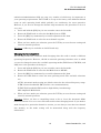
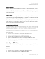
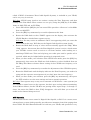
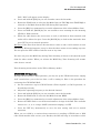
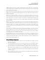
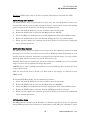
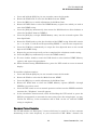
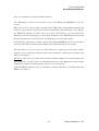
FCC ID: K66VX-2R VX-2R OPERATING MANUAL General Description Accessories & Option Accessories Supplied with the VX-2R FNB-82LI 3.7 V, 1000 mAh Rechargeable Lithium Ion Battery Packs NC-85B/C/U 2.5-Hour Charger Belt Clip Hand Strap Antenna Operating Manual Warranty Card Available Option for your VX-2R FNB-82LI 3.7 V, 1000 mAh Rechargeable Lithium Ion Battery Packs NC-85 B/C/U 2.5-Hour Charger CN-3 BNC-to-SMA Adapter CSC-90 Soft Case CT-44 Microphone Adapter E-DC-21 DC Cable w/ Cigar Adapter MH-34B4B Speaker/Microphone MH-37A4B Ear piece/Microphone VC-25 VOX Headset Control & Connections ANTENNA Connect the supplied rubber flex antenna (or another antenna presenting a 50-Ohm impedance) here. MIC/SP This four conductor miniature jack provides connection points for microphone audio, earphone audio, PTT, and ground. VOLUME This control adjusts the audio volume level. Clockwise rotation increases the volume 1 Vertex Standard Co., Ltd. FCC ID: K66VX-2R VX-2R OPERATING MANUAL level. DIAL The main tuning Dial is used for setting the operating frequency, and also is used for menu selections and other adjustment. TX/BUSY This indicator glows green when the squelch opens, and turns red during transmit. During Emergency Operation, this indicator will glow (or flash) white. PTT (Push To Talk) Press this switch to transmit, and release it (to receive) after your transmission is completed. MONI Pressing this key disables the noise squelching action, allowing you to hear very weak signals near the background noise level. POWER Press and hold this switch for one second to toggle the transceiver’s power on and off. KEYPAD These seven keys select many of most important operating features on the VX-2. This function of the keys are described in details on next page. SPEAKER The internal speaker is located on hear. MIC The internal microphone is located on hear. EXT DC This coaxial DC jack allows connection to an external DC power source (3.2-7.0V DC). The center pin of this jack is the Positive (+). 2 Vertex Standard Co., Ltd. FCC ID: K66VX-2R VX-2R OPERATING MANUAL Keypad Functions Key BAND H/L V/M FW HM/RV % MD Press Key Moves operation to the next-highest frequency band. Switches the transmit power output between “HI” and “LOW.” Switches frequency control between the VFO and Memory System. Activates the “Alternate” key function. Press + [FW] Key Moves operation to the next-lowest frequency band. Select the synthesizer steps to be used during VFO operation. Activates the “Memory Tune” mode while in the Memory Recall mode. Disables the “Alternate” key function. Reverse the transmit and receive frequencies while working through a repeater. Activate the WIRESTM (Internet Connection) feature. Switches operation to the “Home” (favorite frequency) channel. Switches the operating mode. Recall the “Weather” broadcast channels and Short-wave broadcast station channels. Activates the CTCSS or DCS operation. Press and hold Key Activates the Scanner. Enter the “Set” (Menu) mode. Activates the Dual Watch feature. Activates the “Memory Write” mode (for memory channel storage). Activates the Emergency Function. Activates the ARTS feature. Activate the Smart Search feature. Installation of Accessories Antenna Installation The supplied antenna provides good results over the entire frequency range of the transceiver. However, for enhanced base station medium-wave and shortwave reception, you may wish to connect an external (outside) antenna. To install the supplied antenna Hold the bottom end of the antenna, then screw it onto the mating connector on the transceiver until it is snug. Do not over-tighten by use of extreme force. Notes: Never transmit without having an antenna connected. When installing the supplied antenna, never hold the upper part of the antenna while screwing it onto the mating connector on the transceiver. 3 Vertex Standard Co., Ltd. FCC ID: K66VX-2R VX-2R OPERATING MANUAL If using an external antenna for transmission, ensure that the SWR presented to the transceiver is 1.5:1 or lower. Installation of FNB-82LI Battery Pack The FNB-80LI is a high-performance Lithium-Ion battery providing high capacity in a very compact package. Under normal use, the FNB-82LI may be used for approximately 300 charge cycles, after which operating time may be expected to decrease. If you have an old battery pack which is displaying capacity which has become diminished, you should replace the pack with a new one. Referring to Figure 1, slide the Battery Cover toward the bottom to remove it while slide the Battery Cover Latch. Referring to Figure 2, install the FNB-82LI into the Battery Nest. Replace the Battery Cover, as shown in Figure 3. If the battery has never been used, or its charge is depleted, it may be charged by connecting the NC-85 Battery Charger, as shown in the illustration, to the EXT DC jack. If only 12 ~ 16 Volt DC power is available, the optional E-DC-21 DC Adapter (with its cigarette lighter plug) may also be used for charging the battery. While the battery is being charged, display will indicate “CHGING” and the TX/BUSY indicator will glow red. When charging is finished, display will change to indicate “CHGFUL” and the TX/BUSY indicator will change to glow green. Interface of Packet TNCs The VX-2R may be used for Packet operation, using the optional CT-91 microphone adapter (available from your Yaesu dealer) for easy interconnection to commonlyavailable connectors wired to your TNC. You may also build your own cable using a four-conductor miniature phone plug, per the diagram below. The audio level from the receiver to the TNC may be adjusted by using the VOLUME knob, as with voice operation. The input level to the VX-2R from the TNC should be adjusted at the TNC side; the optimum input voltage is approximately 5 mV at 2000 Ohms. Be sure to turn the transceiver and TNC off before connecting the cables, so as to prevent voltage spikes from possibly damaging your transceiver. 4 Vertex Standard Co., Ltd. FCC ID: K66VX-2R VX-2R OPERATING MANUAL Operation R. F. says: Hi! I’m R. F. Radio, and I’ll be helping you along as you learn the many features of the VX-2R. I know you’re anxious to get on the air, but I encourage you to read the “Operation” section of this manual as thoroughly as possible, so you’ll get the most out of this fantastic new transceiver. Now. . .let’s get operating! Switching Power On and Off 1. Be sure the Battery Pack is installed, and that the battery is fully charged. Connect the antenna to the top panel ANTENNA jack. 2. Press and hold in the POWER switch (on the left side of the transceiver) for one second. Two beeps will be heard when the switch has been held long enough, and the current DC supply voltage will indicate on the display for 2 second. After this interval, the display will resume its normal indication of the operating frequency. 3. To turn the VX-2R off, press and hold in the POWER switch again for one second. R.F. says: If you don’t hear the two “Beep” tones when the radio comes on, the Beeper may have been disabled via the Menu system. See page ??, which tells you how to reactivate the Beeper. Adjusting the Volume Level Rotate the VOLUME control (inner knob) to set the desired audio level. Clockwise rotation increases the volume level. Squelch Adjustment The VX-2R’s Squelch system allows you to mute the background noise when no signal is being received. Not only does the Squelch system make “standby” operation more pleasant, it also significantly reduces battery current consumption. The Squelch system may be adjusted independently for the FM and Wide-FM (FM Broadcast) modes. 1. Press and hold the [H/L(STEP)SET] key for one second to enter the Set Mode. 2. Rotate the DIAL knob to select the Set Mode Item 1: SQL. 3. Press the [H/L] key momentarily to enable adjustment this Item. 4. Rotate the DIAL knob to set the background noise is just silenced (typically at a setting of about “1” or “2” for FM, and “2” or “3” for Wide-FM); this is point of maximum sensitivity to weak signals. 5 Vertex Standard Co., Ltd. FCC ID: K66VX-2R VX-2R OPERATING MANUAL 5. When you are satisfied with the Squelch threshold setting, press the PTT key momentarily to save the new setting and exit to normal operation. R.F. Says: 1) A special “RF Squelch” feature is provided on the VX-2R. This feature allows you to set the squelch so that only signals exceeding a certain S-meter level will open the squelch. See page ?? for details. 2) If you’re operating in an area of high RF pollution, you may need to consider “Tone Squelch” operation using the built-in CTCSS Decoder. This feature will keep your radio quiet until a call is received from a station sending a carrier which contains a matching (subaudible) CTCSS tone. Or if your friends have radios equipped with DCS (Digital Coded Squelch) like your VX-2R has, try using that mode for silent monitoring of busy channels. Selecting the Operating Band The VX-2R covers an incredibly wide frequency range, over which a number of different operating modes are used. Therefore, the VX-2R’s frequency coverage has been divided into different operating bands, each of which has its own pre-set channel steps and operating modes. You can change the channel steps and operating modes later, if you like (see page ??). To Change Operating Bands: 1. Press the [BAND] key repetitively. You will see the LCD indication move toward a higher frequency band each time you press the [BAND] key. 2. If you wish to move the operating band selection downward (toward lower frequencies), press the [F/W] key first, then press the [BAND] key. 3. Once you have selected the desired band, you may initiate manual tuning (or scanning) per the discussions on the next chapter. Frequency Navigation The VX-2R will initially be operating in the “VFO” mode, a channelized system which allows free tuning throughout the currently-selected operating band. Two basic frequency navigation methods are available on the VX-2R: 1) Tuning Dial (Outer ring of dual control on Top Panel) Rotation of the DIAL allows tuning in the pre-programmed steps established for the current operating band. Clockwise rotation of the DIAL causes the VX-2R to be tuned toward a higher frequency, while counter-clockwise rotation will lower the operating 6 Vertex Standard Co., Ltd. FCC ID: K66VX-2R VX-2R OPERATING MANUAL frequency. If you press the [F/W] key momentarily, then rotate the DIAL, frequency steps of 1 MHz will be selected. This feature is extremely useful for making rapid frequency excursions over the wide tuning range of the VX-2R. 2) Scanning From the VFO mode, press and hold the [BAND] key. The VX-2R will begin scanning toward a higher frequency, and will stop when it receives a signal strong enough to break through the Squelch threshold. The VX-2R will then hold on that frequency according to the setting of the “RESUME” mode (Set Mode Item 28: RESUME). See page ?? for details. If you wish to reverse the direction of the scan (i.e. toward a lower frequency, instead of a higher frequency), just rotate the DIAL one click in the counter-clockwise direction while the VX-2R is scanning. The scanning direction will be reversed. To revert to scanning toward a higher frequency once more, rotate the DIAL one click clockwise. Press the PTT switch momentarily to cancel the scanning. Transmission Once you have set up an appropriate frequency inside one of the 144 MHz or 430 MHz Amateur bands on which the VX-2R can transmit, you’re ready to transmit. These are the most basic steps; more advanced aspects of transmitter operation will be discussed later. 1. To transmit, press the PTT switch, and speak into the front panel microphone (located in the upper left-hand corner of the speaker grille) in a normal voice level. The TX/BUSY indicator will glow red during transmission. 2. To return to the receive mode, release the PTT switch. 3. During transmission, the relative power level will be indicated on the LCD. Additionally, the “L” icon will appear at the bottom of the display while operating on the “Low Power” Level setting. R.F. Says: If you’re just talking to friends in the immediate area, you’ll get much longer battery life by switching to Low Power operation. To do this, press the [H/L] key so that the “L” icon appears at the bottom of the display. And don’t forget: always have an antenna connected when you transmit. Transmission is possible only on the 144 MHz and 430 MHz bands. R.F. Says: 1) The VX-2R is smart! You can set up Low power on 144 MHz band, while 7 Vertex Standard Co., Ltd. FCC ID: K66VX-2R VX-2R OPERATING MANUAL leaving 430 MHz on High power, and the radio will remember the different settings on both band. And when you store memories, you can store High and Low power settings separately in each memory, so you don’t waste battery power when using very close-in repeaters! 2) When you are operating on one of the Low power settings, you can press the [F/W] key, when press the PTT switch, to cause the VX-2R to transmit (temporarily) on High power. After one transmission, the power level will revert to the previously-selected Low power setting. Keyboard Locking In order to prevent accidental frequency change or inadvertent transmission, various aspects of the VX-2R’s keys and switches may be locked out. The possible lockout combinations are: KEY: Just the front panel keys are locked out DIAL: Just the top panel DIAL is locked out K + D: Both the DIAL and Keys are locked out PTT: The PTT switch is locked (TX not possible) K + P: Both the keys and PTT switch are locked out D + P: Both the DIAL and PTT switch are locked out ALL: All of the above are locked out To lock out some or all of the keys: 1. Press and hold the [H/L] key for one second to enter the Set mode. 2. Rotate the DIAL knob to select the Set Mode Item 9: LOCK. 3. Press the [H/L] key momentarily to enable adjustment this Item. 4. Rotate the DIAL knob to choose between one of the locking schemes as outlined above. 5. When you have made your selection, press the PTT key to save the new setting and return to normal operation. To activate the locking feature, press the [F/W] key, then press and hold the [BAND] key for one second. The “Key Lock” icon will appear on the LCD. To cancel locking, again above procedures. Keypad/LCD Illumination Your VX-2R includes a reddish illumination lamp which aids in nighttime operation. 8 Vertex Standard Co., Ltd. FCC ID: K66VX-2R VX-2R OPERATING MANUAL The red illumination yields clear viewing of the display in a dark environment, with minimal degradation of your night vision. Three options for activating the lamp are provided: KEY Mode: Illuminates the Keypad/LCD for five seconds when any key pressed. CONT Mode: Illuminates the Keypad/LCD continuously. OFF Mode: Disables the Keypad/LCD lamp. Here is the procedure for setting up the Lamp mode: 1. Press and hold the [H/L] key for one second to enter the Set mode. 2. Rotate the DIAL knob to select the Set Mode Item 17: LAMP. 3. Press the [H/L] key momentarily to enable adjustment this Item. 4. Rotate the DIAL knob to select one of the three modes described above. 5. When you have made your choice, press the PTT key to save the new setting and return to normal operation. R.F. Says: You may adjust the Keypad/LCD illumination level and LCD contrast by the Set Mode. See page ?? for details. Disabling the Keypad Beeper If the keypad’s Beeper creates an inconvenience (particularly when operating in a quiet room), it may easily be disabled. 1. Press and hold the [H/L] key for one second to enter the Set mode. 2. Rotate the DIAL knob to select the Set Mode Item 8: BEEP. 3. Press the [H/L] key momentarily to enable adjustment this Item. 4. Rotate the DIAL knob to change the setting from ON to OFF. 5. When you have made your selection, press the PTT key to save the new setting and return to normal operation. 6. If you wish to re-enable the Beeper, just repeat the above procedure, rotate the DIAL knob to select ON in step “4” above. Advanced Operation Now that you’re mastered the basics of VX-2R operation, let’s learn more about some of the really neat features. Changing the Channel Steps The VX-2R’s synthesizer provides the option of utilizing channel steps of 9 Vertex Standard Co., Ltd. FCC ID: K66VX-2R VX-2R OPERATING MANUAL 5/9/10/12.5/15/20/25/50/100 kHz per step, any number of which may be important to your operating requirements. The VX-2R is set up at the factory with different default steps on each operating band which probably are satisfactory for most operation. However, if you need to change the channel step increments, the procedure to do so is very easy. 1. Press and hold the [H/L] key for one second to enter the Set mode. 2. Rotate the DIAL knob to select the Set Mode Item 3: STEP. 3. Press the [H/L] key momentarily to enable adjustment this Item. 4. Rotate the DIAL knob to select the new channel step size. 5. When you have made your selection, press the PTT key to save the new setting and return to normal operation. R.F. Says: 9 kHz step is available on the BC band only. Changing the Operating Mode The VX-2R provides for automatic mode changing when the radio is tuned to different operating frequencies. However, should an unusual operating situation arise in which you need to change between the available operating modes (FM-Narrow, FM-Wide, and AM), here is the procedure for doing so: 1. Press and hold the [H/L] key for one second to enter the Set mode. 2. Rotate the DIAL knob to select the Set Mode Item 4: RX MD. 3. Press the [H/L] key momentarily to enable adjustment this Item. 4. Rotate the DIAL knob to select the new operating mode. The available selections are: AUTO: Automatic mode setting per default values for the selected frequency range. N-FM: Narrow-bandwidth FM (used for voice communication) W-FM: Wide-bandwidth FM (used for high-fidelity broadcasting) AM: Amplitude Modulation 5. When you have made your selection, press the PTT key to save the new setting and return to normal operation. R.F. Says: Unless you have a compelling reason to do so, leave the Automatic Mode Selection feature on so as to save time and trouble when changing bands. If you make a mode change for a particular channel or station, you can always store that one channel into memory, as the mode setting will be memorized along with the frequency information. 10 Vertex Standard Co., Ltd. FCC ID: K66VX-2R VX-2R OPERATING MANUAL Repeater Operation Repeater stations, usually located on mountaintops or other high locations, provide a dramatic extension of the communication range for low-powered hand-held or mobile transceivers. The VX-2R includes a number of features which make repeater operation simple and enjoyable. Repeater Shifts Your VX-2R has been configured, at the factory, for the repeater shifts customary in your country. For the 144 MHz band shift will be 600 kHz; on the 430 MHz band, the shift may be 1.6 MHz, 7.6 MHz, or 5 MHz (USA version). Depending on the part of the band in which you are operating, the repeater shift may be either downward (–) or upward (+), and one of these icons will appear at the bottom of the LCD when repeater shifts have been enabled. Automatic Repeater Shift (ARS) The VX-2R provides a convenient Automatic Repeater Shift feature, which causes the appropriate repeater shift to be automatically applied whenever you tune into the designated repeater sub-bands in your country. These sub-bands are shown below. If the ARS feature does not appear to be working, you may have accidentally disabled it. To re-enable ARS: 1. Press and hold the [H/L] key for one second to enter the Set mode. 2. Rotate the DIAL knob to select the Set Mode Item 5: ARS. 3. Press the [H/L] key momentarily to enable adjustment this Item. 4. Rotate the DIAL knob to select “ON” (to enable Automatic Repeater Shift). 5. When you have made your selection, press the PTT key to save the new setting and return to normal operation. Manual Repeater Shift Activation If the ARS feature has been disabled, or if you need to set a repeater shift direction other than that established by the ARS, you may set the direction of the repeater shift manually. To do this: 1. Press and hold the [H/L] key for one second to enter the Set mode. 2. Rotate the DIAL knob to select the Set Mode Item 7: RPT. 11 Vertex Standard Co., Ltd. FCC ID: K66VX-2R VX-2R OPERATING MANUAL 3. Press the [H/L] key momentarily to enable adjustment this Item. 4. Rotate the DIAL knob to select the desired shift among “–RPT,” “+RPT,” and “SIMP.” 5. When you have made your selection, press the PTT key to save the new setting and return to normal operation. Changing the Default Repeater Shifts If you travel to a different region, you may need to change the default repeater shift so as to ensure compatibility with local operating requirements. To do this, follow the procedure below: 1. Press and hold the [H/L] key for one second to enter the Set mode. 2. Rotate the DIAL knob to select the Set Mode Item 6: SHIFT. 3. Press the [H/L] key momentarily to enable adjustment this Item. 4. Rotate the DIAL knob to select the new repeater shift magnitude. 5. When you have made your selection, press the PTT key to save the new setting and return to normal operation. R.F. Says: If you just have one “odd” split that you need to program, don’t change the “default” repeated shifts using this Menu Item! Enter the transmit and receive frequencies separately, as shown on page ??. Checking the Repeater Uplink (Input) Frequency It often is helpful to be able to check the uplink (input) frequency of a repeater, to see if the calling station is within direct (“Simplex”) range. To do this, just press the [HM/RV] key. You’ll notice that the display has shifted to the repeater uplink frequency. Press the [HM/RV] key again to cause operation to revert to normal monitoring of the repeater downlink (output) frequency. RF Says: The configuration of this key may be set either to “RV” (for checking the input frequency of a repeater, or “HM” (for instant switching to the “Home” channel for the band you are operating on). To change the configuration of this key, use Set Mode Item 40: HM/RV. See page ??. CTCSS Operation Many repeater systems require that a very-low-frequency audio tone be superimposed on your FM carrier in order to activate the repeater. This helps prevent false activation of the repeater by radar or spurious signals from other transmitters. This tone system, 12 Vertex Standard Co., Ltd. FCC ID: K66VX-2R VX-2R OPERATING MANUAL called “CTCSS” (Continuous Tone Coded Squelch System), is included in your VX-2R, and is very easy to activate. R.F. Says: CTCSS setup involves two actions: setting the Tone Frequency and then setting of the Tone Mode. These actions are set up by using the [MD] key or Set Mode Items 18: SQL TYP and 19: TN FRQ. 1. Press and hold the [MD] key for one second. This provides a “Short-cut” to Set Mode Item 18: SQL TYP. 2. Press the [H/L] key momentarily to enable adjustment this Item. 3. Rotate the DIAL knob so that “TONE” appears on the display; this activates the CTCSS Encoder, which allows repeater access. R.F. Says: You may notice an additional “DCS” icon appearing while you rotate the DIAL knob in this step. We’ll discuss the Digital Code Squelch system shortly. 4. Rotate the DIAL knob in step “3” above will occasionally appear the “TSQ.” When “TSQ” appears, this means that the Tone SQueLch system is active, which mutes your VX-2R’s receiver until it receives a call from another radio sending out a matching CTCSS tone. This can help keep your radio quiet until a specific call is received, which may be helpful while operating in congested areas. 5. When you have made your selection of the CTCSS tone mode, press the [H/L] key momentarily, then rotate the DIAL one click clockwise to select Set Mode Item 19: TN FRQ. This Menu selection allows setting of the CTCSS tone frequency to be used. 6. Press the [H/L] key momentarily to enable the adjustment of the CTCSS frequency. 7. Rotate the DIAL knob until the display indicates the Tone Frequency you need to be using (ask the repeater owner/operator if you don’t know the tone frequency). 8. When you have made your selection, press the [H/L] key momentarily, then press the PTT switch to save the new settings and exit to normal operation. R.F. Says: Your repeater may or may not re-transmit a CTCSS tone - some systems just use CTCSS to control access to the repeater, but don’t pass it along when transmitting. If the S-Meter deflects, but the VX-2R is not passing audio, repeat steps “1” through “4” above, but rotate the DIAL so that “TSQ” disappears - this will allow you to hear all traffic on the channel being received. DCS Operation Another form of tone access control is Digital Code Squelch, or DCS. It is a newer, more advanced tone system which generally provides more immunity from false paging than does CTCSS. The DCS Encoder/Decoder is built into your VX-2R, and operation is very 13 Vertex Standard Co., Ltd. FCC ID: K66VX-2R VX-2R OPERATING MANUAL similar to that just described for CTCSS. Your repeater system may be configured for DCS; if not, it is frequently quite useful in Simplex operation if your friend(s) use transceivers equipped with this advanced feature. R.F. Says: Just as in CTCSS operation, DCS requires that you set the Tone Mode to DCS and that you select a tone code. 1. Press and hold the [MD] key for one second. This provides a “Short-cut” to Set Mode Item 18: SQL TY 2. Press the [H/L] key momentarily to enable adjustment this Item. 3. Rotate the DIAL knob until “DCS” appears on the display; this activates the DCS Encoder/Decoder. 4. Press the [H/L] key momentarily, then rotate the DIAL to select Set Mode Item 20: DCS CD). 5. Press the [H/L] key momentarily to enable the adjustment of the DCS code. 6. Rotate the DIAL knob to select the desired DCS Code (a three-digit number). Ask the repeater owner/operator if you don’t know DCS Code; if you are working simplex, just set up the DCS Code to be the same as that used by your friend(s). 7. When you have made your selection, press the [H/L] key momentarily,, then press the PTT switch to save the new settings and exit to normal operation. R.F. Says: Remember that the DCS is an Encode/Decode system, so your receiver will remain muted until a matching DCS code is received on an incoming transmission. Switch the DCS off when you’re just tuning around the band! Tone Search Scanning In operating situations where you don’t know the CTCSS or DCS tone being used by another station or stations, you can command the radio to listen to the incoming signal and scan in search of the tone being used. Two things must be remembered in this regard: You must be sure that your repeater uses the same tone type (CTCSS vs. DCS). Some repeaters do not pass the CTCSS tone; you may have to listen to the station(s) transmitting on the repeater uplink (input) frequency in order to allow Tone Search Scanning to work. To scan for the tone in use: 1. Set the radio up for either CTCSS or DCS Decoder operation (see the previous discussion). In the case of CTCSS, “TSQ” will appear on the display; in the case of 14 Vertex Standard Co., Ltd. FCC ID: K66VX-2R VX-2R OPERATING MANUAL DCS, “DCS” will appear on the display. 2. Press and hold the [H/L] key for one second to enter the Set mode. 3. Rotate the DIAL knob to select the Set Mode Item 19: TN FRQ when TONE SQL is selected, or Set Mode Item 20 DCS CD during DCS operation. 4. Press the [H/L] key momentarily to enable adjustment of the selected Menu Item. 5. Press and hold the [BAND] key for one second to start scanning for the incoming CTCSS or DCS tone/code. 6. When the radio detects the correct tone or code, it will halt on that tone/code, and audio will be allowed to pass. Press the [BAND] key to lock in that tone/code, then press PTT to exit to normal operation. R.F. Says: If the Tone Scan feature does not detect a tone or code, it will continue to scan indefinitely. When this happens, it may be that the other station is not sending any tone. You can press the PTT switch to halt the scan at any time. You also can press the MONI key during Tone Scanning to listen to the (muted) signal from the other station. When you release the MONI key, Tone Scanning will resume after about a second. Tone Scanning works either in the VFO or Memory modes. CTCSS/DCS Bell Operation During CTCSS Decode or DCS operation, you may set up the VX-2R such that a ringing “bell” sound alerts you to the fact that a call is coming in. Here is the procedure for activating the CTCSS/DCS Bell: 1. Set the transceiver up for CTCSS Decode (“Tone Squelch”) or DCS operation, as described previously. 2. Adjust the operating frequency to the desired channel. 3. Press and hold the [H/L] key for one second to enter the Set mode. 4. Rotate the DIAL knob to select the Set Mode Item 22: BELL. 5. Press the [H/L] key momentarily to enable adjustment of the selected Menu Item. 6. Rotate the DIAL knob to set the desired number of rings of the Bell. The available choices are 1, 3, 5, or 8 rings, CONT (continuous ringing), or OFF. 7. Press the PTT key momentarily to save the new setting and exit to normal operation. When you are called by a station whose transceiver is sending a CTCSS tone or DCS code which matches that set into your Decoder, the Bell will ring in accordance to this 15 Vertex Standard Co., Ltd. FCC ID: K66VX-2R VX-2R OPERATING MANUAL programming. Split Tone Operation The VX-2R can be operated in a Split Tone configuration via the Set mode. 1. Press and hold the [H/L] key for one second to enter the Set mode. 2. Rotate the DIAL knob to select the Set Mode Item 23: SPLIT. 3. Press the [H/L] key momentarily to enable adjustment of the selected Menu Item. 4. Rotate the DIAL knob to select ON (to enable the Split Tone feature). 5. Press the PTT key momentarily to save the new setting and exit to normal operation. When the Split Tone feature is activated, you can see the following additional parameters after the “DCS” parameter while selecting the Set Mode Item 18: SQL TYP: D CODE: DCS Encode only T DCS: Encodes a CTCSS Tone and Decodes a DCS code D TONE: Encodes a DCS code and Decodes a CTCSS Tone Select the desired operating mode from the selections shown above. Tone Calling (1750 Hz) If the repeaters in your country require a 1750-Hz burst tone for access (typically in Europe), you can set the MONI key to serve as a “Tone Call” switch instead. To change the configuration of this switch, we again use the Menu to help us. 1. Press and hold the [H/L] key for one second to enter the Set mode. 2. Rotate the DIAL knob to select the Set Mode Item 41: M/T-CL. 3. Press the [H/L] key momentarily to enable adjustment of the selected Menu Item. 4. Rotate the DIAL knob to select “T-CALL” on the display. 5. Press the PTT key to save the new setting and exit to normal operation. To access a repeater, press and hold in the MONI key for the amount of time specified by the repeater owner/operator. The transmitter will automatically be activated, and a 1750-Hz audio tone will be superimposed on the carrier. Once access to the repeater has been gained, you may release the MONI key, and use the PTT key for activating the transmitter. ARTS (Automatic Range Transponder System) The ARTS feature uses DCS signaling to inform both parties when you and another 16 Vertex Standard Co., Ltd. FCC ID: K66VX-2R VX-2R OPERATING MANUAL ARTS-equipped station are within communications range. This may be particularly useful during Search-and Rescue situations, where is important to stay in contact with other members of your group. Both stations must set up their DCS codes to the same code number, then activate their ARTS feature using the command appropriate for their radio. Alert ringers may be activated, if desired. Whenever you push the PTT, or every 25 (or 15) seconds after ARTS is activated, your radio will transmit a signal which includes a (subaudible) DCS signal for about 1 second. If the other radio is in range, the beeper will sound (if enabled) and the display will show “IN RNG” as opposed to the out of range display “OUT RNG” in which ARTS operation begins. Whether you talk or not, the polling every 15 or 25 seconds will continue until you deactivate ARTS. Every 10 minutes, moreover, you can have your radio transmit your callsign via CW, so as to comply with identification requirements. When ARTS is deactivated, DCS will also be deactivated (if you were not using it previously in non-ARTS operation). If you move out of range for more than one minute (four pollings), your radio will sense that no signal has been received, three beeps will sound, and the display will revert to “OUT RNG.” If you move back into range, your radio will again beep, and the display will change back to the “IN RNG” indication. During ARTS operation, your operating frequency will continue to be displayed, but no changes may be made to it or other settings; you must terminate ARTS in order to resume normal operation. This is a safety feature designed to prevent accidental loss of contact due to channel change, etc. Basic ARTS Setup and Operation 1. Set your radio and the other radio(s) to the same DCS code number, per the discussion on page ??. 2. Press and hold the [%] key for one second. You will observe the “OUT RNG” display on the LCD below the operating frequency. ARTS operation has now commenced. 3. Every 25 seconds, your radio will transmit a “polling” call to the other station. When that station responds with its own ARTS polling signal, the display will change to “IN RNG” to confirm that the other station’s polling code was received in response to yours. 4. Press and hold the [%] key for one second to exit ARTS operation and resume normal functioning of the transceiver. 17 Vertex Standard Co., Ltd. FCC ID: K66VX-2R VX-2R OPERATING MANUAL R.F. Says: ARTS won’t work if you have used the Lock feature to disable the PTT! ARTS Polling Time Options The ARTS feature may be programmed to poll every 25 seconds (default value) or 15 seconds. The default value provides maximum battery conservation, because the polling signal is sent out less frequently. To change the polling interval: 1. Press and hold the [H/L] key for one second to enter the Set mode. 2. Rotate the DIAL knob to select the Set Mode Item 38: AR INT. 3. Press the [H/L] key momentarily to enable adjustment of the selected Menu Item. 4. Rotate the DIAL knob to select the desired polling interval (15 or 25 seconds). 5. When you have made your selection, press the PTT key to save the new setting and exit to normal operation. ARTS Alert Beep Options The ARTS feature allows two kinds of alert beeps (with the additional option of turning them off), so as to alert you to the current status of ARTS operation. Depending on your location and the potential annoyance associated with frequent beeps, you may choose the Beep mode which best suits your needs. The choices are: IN RNG: The beeps are issued only when the radio first confirms that you are within range, but does not re-confirm with beeps thereafter. ALWAYS: Every time a polling transmission is received from the other station, the alert beeps will be heard. OFF: No alert beeps will be heard; you must look at the display to confirm current ARTS status. To set the ARTS Beep mode, use the following procedure: 1. Press and hold the [H/L] key for one second to enter the Set mode. 2. Rotate the DIAL knob to select the Set Mode Item 37: ARTSBP. 3. Press the [H/L] key momentarily to enable adjustment of the selected Menu Item. 4. Rotate the DIAL knob to select the desired ARTS Beep mode (see above). 5. When you have made your selection, press the PTT key to save the new setting and exit to normal operation. CW Identifier Setup The ARTS feature includes a CW identifier, as discussed previously. Every ten minutes during ARTS operation, the radio can be instructed to send “DE (your callsign) K” if this 18 Vertex Standard Co., Ltd. FCC ID: K66VX-2R VX-2R OPERATING MANUAL feature is enabled. The callsign field may contain up to 16 characters. Here’s how to program the CW Identifier: 1. Press and hold the [H/L] key for one second to enter the Set mode. 2. Rotate the DIAL knob to select the Set Mode Item 39: CW ID. 3. Press the [H/L] key momentarily to enable adjustment of the selected Menu Item. 4. Rotate the DIAL knob to select ON (to enable the CW ID function). 5. Press the [MH/RV] key momentarily to clear any previous callsign. 6. Rotate the DIAL knob to select the first letter/number of your callsign, then press the [V/M] key momentarily to save the first letter/number and move on to the next character. 7. Repeat the previous step as necessary to complete your callsign. Note that the “slant bar” (– • • – •) is among the available characters, should you be a “portable” station. 8. If you mistake, press the [BAND] key to back-space the cursor, re-enter the correct letter/number. 9. Press the [HM/RV] key to delete all data after the cursor that may have been previously stored erroneously. 10. When you have entered your entire callsign, press the [H/L] key momentarily to confirm the callsign, then press the PTT key to save the settings and exit to normal operation. R.F. Says: You may check your work by monitoring the entered callsign. To do this, repeat steps 1- 3 above, then press the [MON/F] key. DTMF Operation Despite the lack of a DTMF keypad, you can still transmit DTMF tones with the VX-2R for repeater control or autopatch use. Manual DTMF Tone Generation DTMF Autodialer Nine DTMF Autodial memories are provided, allowing you to store telephone numbers for autopatch use. You can also store short autopatch or Internet-link access code streams so as to avoid having to send them manually. Here is the DTMF Autodial storage procedure: 19 Vertex Standard Co., Ltd. FCC ID: K66VX-2R VX-2R OPERATING MANUAL 1. Press and hold the [H/L] key for one second to enter the Set mode. 2. Rotate the DIAL knob to select the Set Mode Item 24: DTMF. 3. Press the [H/L] key to enable adjustment of this Menu Item. 4. Rotate the DIAL knob to select the DTMF Memory register into which you wish to store this DTMF string. 5. Press the [H/L] key momentarily, then rotate the DIAL knob one click clockwise to select the Set Mode Item 25: DTMF S. 6. Press the [H/L] key to begin DTMF Memory entry into the selected register. The first digit blinks. 7. Rotate the DIAL knob to select the first digit of the DTMF string. Selectable entries are 1 - 9, and A - F, with E and F representing DTMF “*” and “#” tones respectively. 8. Press the [V/M] key momentarily to accept the first digit and move to the second digit of the DTMF string. 9. Repeat the previous steps until you have completed the telephone number string. 10. Press the [H/L] key momentarily to store the DTMF memory. 11. To store another number, rotate the DIAL knob to select another DTMF Memory register, and repeat this procedures. 12. When finished storing DTMF Memories, press the PTT switch to return to normal display. To send the telephone number: 1. Press and hold the [H/L] key for one second to enter the Set mode. 2. Rotate the DIAL to select the Set Mode Item 24: DTMF. 3. Press the [H/L] key to enable adjustment of this Menu Item. 4. Rotate the DIAL knob to select the DTMF Memory register (DTMF 1 through DTMF 9) you wish to send. 5. Press the PTT switch to exit to normal operation and activate the DTMF Autodialer function (the “Telephone” icon will appear). 6. In the Autodialer function mode, while still holding the PTT switch in, press the [H/L] key momentarily to transmit the tone string. Once the string begins, you may release the PTT key, as the transmitter will be held “on the air” until the DTMF string is completed. Emergency Channel Operation The VX-2R includes an “Emergency” feature which may be useful if you have someone monitoring on the same frequency as your transceiver’s UHF “Home” channel. See 20 Vertex Standard Co., Ltd. FCC ID: K66VX-2R VX-2R OPERATING MANUAL page ?? for details on setting the Home channel. The “Emergency” feature is activated by press and holding the [HM/RV] key for one second. When this is done, (A) the radio is placed on the UHF amateur band Home channel, (B) it emits a loud “Alarm” sound (the volume is controlled by the VOL knob), (C) it flashes the TX/BUSY indicator in white, (D) if you press the PTT key, you will disable the Emergency feature temporarily; you can then transmit on the UHF Home channel, and (E) two seconds after the PTT release, the Emergency feature will resume. To disable the “Emergency” feature, press and hold the [HM/RV] key for one second or turn the radio Off by pressing and holding in the [PWR] switch for one second. Use this feature if you are out for a walk and want a quick way of alerting a family member as to a dangerous situation. The alarm sound may discourage an attacker and allow you to escape. R.F. Says: 1) Be sure to arrange with a friend or family member to be monitoring on the same frequency, as there will be no identification sent via the Emergency alarm sound. And do not transmit the alarm tone except in a true emergency! 2) The TX/BUSY indicator may be changed to another function via Set Mode Item 42: EMG S; see page xx. 21 Vertex Standard Co., Ltd.