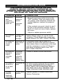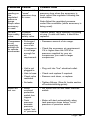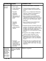
1
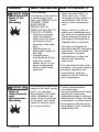
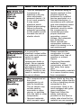
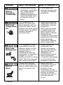
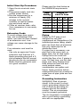
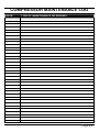
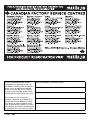
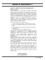
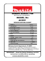
OWNERS MANUAL FOR
Oil Free Air Compressor
MODEL No
$C
SPECIFICATION CHART
Model #
AC001
Horsepower
1/6 HP
SCFM @ 40 PSIG
0.58
SCFM @ 90 PSIG
0.45
Cut-In Pressure
95 PSI
Cut-Out Pressure
125 PSI
Bore
32 mm
Stroke
11 mm
Voltage -Single Phase
Motor RPM
Amperage @ max pressure
120
3400
1.8
Tank Size
1 Gallon
CSA/US Listed
Yes
Minimum Circuit Requirement: 15 AMPS
*A circuit breaker is preferred. Use only a fuse or circuit
breaker that is the same rating as the branch circuit the air
compressor is operated on. If the air compressor is connected
to a circuit protected by fuses, use time delay fuses.
IMPORTANT — Read the Safety Guidelines and ALL
instructions carefully before operating.
www.makita.com
TABLE OF CONTENTS
SAFETY INSTRUCTIONS . . . . . . . . . . . . . . . . . . . . . . . . . . . . . . . . 3
Warning Chart . . . . . . . . . . . . . . . . . . . . . . . . . . . . . . . . . . . . . . . 3
GLOSSARY . . . . . . . . . . . . . . . . . . . . . . . . . . . . . . . . . . . . . . . . . . . . 7
DUTY CYCLE . . . . . . . . . . . . . . . . . . . . . . . . . . . . . . . . . . . . . . . . . . 7
GENERAL INFORMATION . . . . . . . . . . . . . . . . . . . . . . . . . . . . . . . . . 7
ON-RECEIPT INSPECTION . . . . . . . . . . . . . . . . . . . . . . . . . . . . . . . 7
STORAGE . . . . . . . . . . . . . . . . . . . . . . . . . . . . . . . . . . . . . . . . . . . . . 8
DESCRIPTION OF OPERATION . . . . . . . . . . . . . . . . . . . . . . . . . . . 8
INSTALLATION and BREAK-IN PROCEDURES . . . . . . . . . . . . . . . 9
Location Of the Air Compressor . . . . . . . . . . . . . . . . . . . . . . . . . .9
Initial Start Up Procedure: . . . . . . . . . . . . . . . . . . . . . . . . . . . . . .10
Extension Cords . . . . . . . . . . . . . . . . . . . . . . . . . . . . . . . . . . . . .10
Piping . . . . . . . . . . . . . . . . . . . . . . . . . . . . . . . . . . . . . . . . . . . . .10
Grounding Instruction . . . . . . . . . . . . . . . . . . . . . . . . . . . . . . . . .10
OPERATING PROCEDURES . . . . . . . . . . . . . . . . . . . . . . . . . . . . . 11
Daily Start-up Checklist . . . . . . . . . . . . . . . . . . . . . . . . . . . . . . . .11
MAINTENANCE . . . . . . . . . . . . . . . . . . . . . . . . . . . . . . . . . . . . . . . 12
ROUTINE MAINTENANCE SCHEDULE . . . . . . . . . . . . . . . . . . . . 12
SERVICE INSTRUCTIONS . . . . . . . . . . . . . . . . . . . . . . . . . . . . . . . 13
TROUBLESHOOTING GUIDE . . . . . . . . . . . . . . . . . . . . . . . . . . . . 14
MAINTENANCE LOG . . . . . . . . . . . . . . . . . . . . . . . . . . . . . . . . . . . 17
SERVICE CENTERS . . . . . . . . . . . . . . . . . . . . . . . . . . . . . . . . . . . . 18
WARRANTY . . . . . . . . . . . . . . . . . . . . . . . . . . . . . . . . . . . . . . . . . . .19
Page 2
IMPORTANT SAFETY INSTRUCTIONS
*SAVE THESE INSTRUCTIONS*
WARNING
IMPROPER OPERATION OR MAINTENANCE OF
THIS PRODUCT COULD RESULT IN SERIOUS
INJURY AND PROPERTY DAMAGE.
READ AND UNDERSTAND ALL WARNINGS
AND OPERATING INSTRUCTIONS BEFORE
USING THIS EQUIPMENT.
HAZARD
Risk of
Unsafe
Operation
WHAT CAN HAPPEN
HOW TO PREVENT IT
Unsafe operation of
your air compressor
could lead to serious
injury to you or others.
• Review and understand
all instructions and
warnings in this
manual.
• Become familiar with
the operation and
controls of the air
compressor.
• Keep operating area
clear of all persons,
pets, and obstacles.
• Keep children away
from the air
compressor at all
times.
• Do not operate the
product when fatigued
or under the influence
of alcohol or drugs.
Stay alert at all times.
• Never defeat the safety
features of this product.
• Equip area of operation
with a fire extinguisher.
• Do not operate
machine with missing,
broken, or
unauthorized parts.
Page 3
HAZARD
Risk of Air
Tank
Bursting
Risk of
Attachments
and
Accessories
Bursting
Page 4
WHAT CAN HAPPEN
HOW TO PREVENT IT
The following
conditions could lead to
a weakening of the
tank, and RESULT IN A
VIOLENT TANK
EXPLOSION
RESULTING IN
SERIOUS INJURY TO
YOU OR OTHERS:
• Failure to properly
drain condensed
water from the tank,
causing rust and
thinning of the tank
wall.
• Modifications or
attempted repairs to
the tank.
• Unauthorized
modifications to the
pressure switch,
safety valve, or any
other components,
which control tank
pressure.
· Drain the tank DAILY or
after each use. If tank
develops a leak, replace it
immediately with a new
tank or new compressor
unit.
· Never drill into, weld, or
make any modifications to
the tank or its attachments.
Never attempt to repair a
damaged or leaking tank.
Replace with a new tank.
· The tank is designed to
withstand specific operating
pressures. Never make
adjustments or parts
substitutions to alter the
factory set operating
pressures.
· For essential control of air
pressure, you must install a
pressure regulator and
regulated air pressure
guage to the air outlet of
your compressor.
Exceeding the pressure · Follow the equipment
rating of air tools, spray
manufacturers
guns, air operated
recommendation and never
accessories, tires AND
exceed the maximum
other inflatables can
allowable pressure rating of
cause them to explode
attachments. Never use the
or fly apart, and could
compressor to inflate small
result in serious injury
low-pressure objects such
to you and others.
as children's toys, footballs,
basketballs, etc.
HAZARD
Risk of
Electric
Shock
Risk of
Explosion or
Fire
Risk to
Breathing
WHAT CAN HAPPEN HOW TO PREVENT IT
• Your air compressor
is powered by
electricity. Like any
other electrically
powered device, if it
is not used properly,
it may cause
electrical shock.
• Electrical grounding:
failure to provide
adequate grounding
to this product could
increase the risk of
electric shock.
• Any electrical wiring or
repairs required to this
product should be
performed by qualified
service personnel or a
licensed electrician, in
accordance with national
and local electrical codes.
• Make certain that the
electrical circuit to which
the compressor is
connected provides
proper electrical
grounding, correct
voltage, and adequate
fuse protection.
• Never operate the
compressor outdoors
when it is raining, or in a
wet environment.
It is normal for
electrical contact within
the motor and pressure
switch to spark,
whenever the
compressor starts or
stops. Never operate
the compressor in an
atmosphere where
flammable vapors are
present. Doing so can
result in serious injury
to you or others.
• Always operate the
compressor in a wellventilated area, free of
gasoline or solvent
vapors.
• If spraying flammable
materials, locate
compressor at least 20
feet away from spray
area.
• Store flammable materials
in a secure location away
from compressor.
• The compressed air
• Never inhale air from the
from your
compressor, either directly
compressor is not
or from a breathing device
safe for breathing.
connected to the
The air stream may
compressor. Work in an
contain carbon
area equipped with good
monoxide or other
cross ventilation.
vapors, or particles
• Read and follow the
from the tank or other
safety instructions
components.
provided on the label or
• Sprayed materials
safety data sheet for the
such as paint, paint
material you are spraying.
Page 5
HAZARD
Risk to
Breathing
(continued)
Risk from
Compressed
Air
Risk from
Moving Parts
Risk of
Burn
Page 6
WHAT CAN HAPPEN
solvents, paint remover,
insecticides, weed killers,
etc., contain harmful
vapors and poisons.
• Breathing compressor or
sprayed materials vapor
can result in serious
injury.
HOW TO PREVENT IT
Use an approved
respirator designed for
use with your specific
application.
The compressed air
• Always wear approved
stream can cause soft
safety glasses with side
tissue damage, and can
shields when using the
propel dirt, chips, loose
compressor.
particles and small objects • Never point any nozzle
at high speed, resulting in
or sprayer toward any
property damage or
part of the body or at
personal injury.
other people or animals.
• Always turn the
compressor off and bleed
pressure from the air line
before attempting
maintenance, attaching
tools or accessories.
The compressor cycles
• Always unplug the
automatically when the
compressor and
pressure switch is in the
release air pressure
on/auto position. If you
from the tank and any
attempt repair or
attachments before
maintenance while the
attempting any
compressor is operating or
maintenance or repair.
plugged in, you can
• Never operate the
expose yourself to moving
compressor with guards
parts. These moving parts
or covers which are
can cause serious injury.
damaged or removed.
Contact with hot parts
such as the compressor
head or outlet tubes could
result in a serious skin
burn.
• Never touch hot
components during or
immediately after
operation of the
compressor. Do not
reach around protective
shrouds or attempt
maintenance until unit
has been allowed
to cool.
GLOSSARY
CFM: Cubic feet per minute.
SCFM: Standard cubic feet per
minute; a unit of measure of air
delivery.
PSIG: Pounds per square inch
gauge; a unit of measure of
pressure.
CUT-IN PRESSURE: While the
motor is off, air tank pressure
drops as you continue to use
your accessory or air tool. When
the tank pressure drops to a
certain level the motor will restart
automatically re-started is called
"cut-in pressure".
CUT-OUT PRESSURE: When
you turn on your air compressor,
it begins to run, air pressure in
the air tank begins to build. It
builds to a certain pressure
before the motor automatically
shuts off - protecting your air
tank from pressure higher than
its design rating. The pressure at
which the motor shuts off is
called "cut-out pressure".
DUTY CYCLE
All Makita manufactured air
compressors are recommended
to be operated on not more than
a 50% duty cycle. This means an
air compressor that pumps air
more than 50% of one hour is
considered misuse because the
air compressor is undersized for
the required air demand.
GENERAL
INFORMATION
This air compressor does not use oil.
Now you can enjoy all the
benefits of having an oil free
air compressor.
compressor. When oil is changed
regularly, it will give you long,
trouble-free life.
Your air compressor can be used
for operating paint spray guns,
air tools, caulking guns, grease
guns, air brushes, sandblaster,
inflating tires or spraying weed
killers, insecticides, etc. An air
pressure regulator is supplied for
these applications.
Separate air transformers which
combine the functions of air
regulation and/or moisture and
dirt removal should be used
where applicable.
ON-RECEIPT
INSPECTION
DAMAGE: Each air compressor
outfit is carefully tested and
checked before shipment. With
improper handling, damage may
result in transit and cause
problems with compressor
operation.
Immediately upon arrival, check
equipment for both concealed
and visible damages to avoid
expenses being incurred to
correct such problems. This
should be done regardless of
any visible signs of damage to
the shipping container. If this
Page 7
product was shipped directly to
you, report any damages to the
carrier and arrange for inspection
of goods immediately.
STORAGE
Before you store the air
compressor, make sure you do
the following:
1. Review the “Maintenance” and
“Operating Procedures”
sections and perform
maintenance as necessary. Be
sure to drain water from the
air tank.
2. Protect the electrical cord and
air hose from damage (such as
being stepped on or run over).
Store the air compressor in a
clean and dry location.
DESCRIPTION OF
OPERATION
DRAIN VALVE: The drain valve
is located at the bottom of the
air tank and is used to drain
condensation at the end of
each use.
MOTOR THERMAL OVERLOAD
PROTECTOR: The electric motor
has an automatic thermal overload
protector. If the motor overheats
for any reason, the thermal
overload protector will shut off
the motor. Turn pressure switch
to the “off” position and wait for
unit to cool before pushing the
reset button and restarting the
compressor.
ON/AUTO - OFF SWITCH: Turn
this switch to “on” to provide
automatic power to the pressure
Page 8
switch and to “off” to remove
power when finished using the
compressor or when compressor
will be left unattended.
AIR INTAKE FILTER: This filter is
designed to clean air coming into
the compressor pump. This filter
must always be clean and free
from obstructions. See
“Maintenance”.
AIR COMPRESSOR PUMP: To
compress air, the piston moves
up and down in the cylinder. On
the down stroke, air is drawn in
through the air intake valve. The
exhaust valve remains closed.
On the upstroke of the piston, air
is compressed. The intake valve
closes and compressed air is
forced out through the exhaust
valve, through the outlet tube,
through the check valve and into
the air tank. Useable air is not
available until the compressor
has raised the air tank pressure
above that required at the air
outlet.
CHECK VALVE: When the air
compressor is operating, the
check valve is “open”, allowing
compressed air to enter the air
tank. When the air compressor
reaches “cut-out” pressure, the
check valve “closes”, allowing air
pressure to remain inside the air
tank.
PRESSURE SWITCH
UNLOADING VALVE: The
pressure switch unloading valve
located on the side of the
pressure switch, is designed to
automatically release
compressed air from the
compressor head and the outlet
tube when the air compressor
reaches “cut-out” pressure.
PRESSURE SWITCH: The
pressure switch automatically
starts the motor when the air
tank pressure drops to the
factory set “cut-in” pressure. It
stops the motor when the air
tank pressure reaches the
factory set “cut-out” pressure.
SAFETY VALVE: If the pressure
switch does not shut off the air
compressor at its “cut-out”
pressure setting, the safety valve
will protect against high pressure
by “popping out” at its factory set
pressure (slightly higher than the
pressure switch “cut-out” setting).
OUTLET PRESSURE GAUGE:
The outlet pressure gauge
indicates the air pressure
available at the outlet side of the
regulator. This pressure is
controlled by the regulator and is
always less or equal to the tank
pressure. See “Operating
Procedures”.
TANK PRESSURE GAUGE: The
tank pressure gauge indicates
the air pressure in the tank.
REGULATOR: The air pressure
coming from the air tank is
controlled by the regulator knob.
Turn the knob clockwise to
increase pressure and counterclockwise to decrease pressure.
To avoid minor re-adjustment
after making a change in
pressure setting, always
approach the desired pressure
from a lower pressure. When
reducing from a higher to a lower
setting, first reduce to some
pressure less than desired
pressure. Depending on the air
requirements of each particular
accessory, the outlet regulated
air pressure may have to be
adjusted while you are operating
the accessory.
INSTALLATION AND
BREAK-IN
PROCEDURES
LOCATION OF THE AIR
COMPRESSOR
Locate the air compressor in a
clean, dry and well-ventilated
area. The air intake must be kept
clear of obstructions, which could
reduce air delivery of the air
compressor. The air compressor
should be located at least 12
inches away from the wall or
other obstructions that will
interfere with the flow of air. The
air compressor head and shroud
are designed to allow for proper
cooling. If humidity is high, an air
filter can be installed on the air
outlet adapter to remove
excessive moisture.
LUBRICATION AND OIL
CAUTION: Do not attempt to
operate this air compressor
without first adding oil to the
crankcase. Serious damage will
result from even limited operation
unless filled with oil and broken
in correctly. Make sure to closely
follow initial start-up procedures.
Compressor oil is provided; on a
level surface, please fill the
crankcase to proper level
indicated on the sight glass.
WARNING: Compressors are
shipped without oil. A small
Page 9
Initial Start Up Procedure:
1.Open the air receiver's drain
valve.
2.Plug power supply cord into
correct power source.
3.Run the compressor for a
minimum of twenty (20)
minutes in the no-load
condition to seat the piston
ring and check valves.
4.Close air receiver drain valve.
Your compressor is now ready
for use.
Extension Cords
To avoid voltage drop, power
loss, and overheating of the
motor, use extra air hose instead
of an extension cord. Low
voltage can cause damage to the
motor.
If an extension cord must be
used:
· Use only an approved 3-wire
extension cord that has a 3blade grounding plug and a 3slot receptacle that will accept
the plug on the air compressor.
· Make sure the extension cord
is in good condition.
Please see the chart below as
the MINIMUM requirements:
Amp
Rating
(120 Volts)
10-12
12-14
14-16
16-18
18-20
Length of
Cord in Feet
25'
16
16
16
14
14
50'
14
12
12
12
12
100'
10
10
10
8
8
150'
8
8
8
8
6
Piping
Plastic or PVC pipe is not
designed for use with
compressed air. Regardless of its
indicated pressure rating, plastic
pipe can burst from air pressure.
Use only metal pipe for air
distribution lines.
If a pipe line is necessary, use
pipe that is the same size, or
larger than, the air tank outlet.
Piping that is too small will
restrict the flow of air. If piping is
over 100 feet long, use the next
larger size. Bury underground
lines below the frost line and
avoid pockets where
condensation can gather and
freeze. Apply pressure before
underground lines are covered to
make sure all pipe joints are free
of leaks.
Grounding Instruction
WARNING: Risk of electric
shock! In the event if a short
circuit, grounding reduces the
risk of shock by providing an
escape wire for the electric
current. This air compressor
must be properly grounded.
The air compressor is equipped
with a cord having a grounding
wire with an appropriate
Page 10
grounding plug. The plug must
be used with an outlet that has
been installed and grounded in
accordance with all local codes
and ordinances. The outlet must
have the same configuration as
the plug. DO NOT USE AN
ADAPTER.
Inspect the plug and cord before
each use. Do not use if there are
signs of damage.
DANGER: Improper grounding
can result in electrical shock. Do
not modify the plug that has
been provided. If it does not fit
the available outlet, the correct
outlet should be installed by a
qualified electrician.
OPERATING
PROCEDURES
Daily Start-up Checklist
1. Before attaching air hose or
accessories, make sure the
pressure switch lever is set to
“OFF” and the air regulator or
shut-off valve is closed.
2. Attach hose and accessories.
Too much air pressure causes
a hazardous risk of bursting.
Check the manufacturer's
maximum pressure rating for
air tools and accessories. The
regulator outlet pressure must
never exceed the maximum
pressure rating.
3. Turn the pressure switch lever
to “ON/AUTO” and allow tank
pressure to build. Motor will
stop when tank pressure
reaches “cut-out” pressure.
4. Open the regulator by turning
it clockwise. Adjust the
regulator to the correct
pressure setting. Your
compressor is ready for use.
5. Always operate the air
compressor in well-ventilated
areas; free of gasoline or
other solvent vapors. Do not
operate the compressor near
the spray area.
When you are finished:
6. Set the pressure switch lever
to “OFF”.
7. Using the air tool or
accessory, bleed the tank
pressure down to zero.
8. Remove the air tool or
accessory.
9. Drain water from air tank by
opening drain cock valve on
bottom of tank. WATER WILL
CONDENSE IN THE AIR
TANK. IF NOT DRAINED,
WATER WILL CORRODE
AND WEAKEN THE AIR
TANK CAUSING A RISK OF
AIR TANK RUPTURE.
Note:
If drain cock valve is plugged,
release all air pressure. The
valve can then be removed,
cleaned, then reinstalled.
10. After the water has been
drained, close the drain valve.
The air compressor can now
be stored.
Page 11
MAINTENANCE
WARNING: UNIT CYCLES
AUTOMATICALLY WHEN
POWER IS ON. WHEN
DOING MAINTENANCE,
YOU MAY BE EXPOSED
TO VOLTAGE SOURCES,
COMPRESSED AIR OR
MOVING PARTS. PERSONAL
INJURIES CAN OCCUR.
BEFORE PERFORMING
ANY MAINTENANCE OR
REPAIR, UNPLUG THE
COMPRESSOR AND BLEED
OFF ALL AIR PRESSURE.
To ensure efficient operation and
longer life of the air compressor
unit, a routine maintenance
schedule should be prepared
and followed. The following
routine maintenance schedule is
geared to a unit in a normal
working environment operating
on a daily basis. If necessary, the
schedule should be modified to
suit the conditions under which
your compressor is used. The
modifications will depend upon
the hours of operation and the
working environment.
Compressor units in an
extremely dirty and/or hostile
environment will require a
greater frequency of all
maintenance checks.
Page 12
ROUTINE
MAINTENANCE
SCHEDULE
1. Drain water from the air tank,
any moisture separators or
transformers.
2. Check for any unusual noise
and/or vibration.
3. Manually check all safety
valves to make sure they are
operating properly.
4. Inspect air lines and fittings for
leaks; correct as necessary.
Each year of operation or if a
problem is suspected:
• Check condition of air
compressor pump intake and
exhaust valves.
• Check condition of check
valve. Replace if damaged or
worn out.
WARNING:
Do NOT use this compressor
in locations where the temperature
drops to or below 32 degrees F
or where the ambient temperature
exceeds 104 degrees F.
Allow oil to drain completely.
2.Replace the oil drain plug (The
use of a sealing compound or
Teflon tape to avoid leakage is
recommended.)
3.Refill with the recommended oil
to the proper level.
SERVICE
INSTRUCTIONS
Air Filter - Inspection and
Replacement:
• Keep the air filter clean at all
times. Do not operate the
compressor with the air filter
removed.
• A dirty air filter will not allow
the compressor to operate at
full capacity. Before you use
the compressor, check the air
filter to be sure it is clean.
• If it is dirty, check and replace
the filter element .
WARNING: SAFETY
VALVE – INSPECTION
IF THE SAFETY VALVE
DOES NOT WORK
PROPERLY, OVERPRESSURIZATION MAY
OCCUR, CAUSING AIR
TANK RUPTURE OR
AN EXPLOSION.
OCCASIONALLY PULL
THE RING ON THE
SAFETY VALVE TO MAKE
SURE THAT THE SAFETY
VALVE OPERATES FREELY.
IF THE VALVE IS STUCK
OR DOES NOT OPERATE
SMOOTHLY, IT MUST BE
REPLACED WITH THE
SAME TYPE OF VALVE.
Units with External Brass
Check Valve Replacement
1. Release all air pressure from
air tank and unplug outfit.
2. Remove shroud.
3. Loosen the top and bottom nut
of the outlet tube and remove.
4. Remove the pressure release
tube and fitting.
5. Unscrew the check valve (turn
counterclockwise) using a
socket wrench.
6. Check that the valve disc
moves freely inside the check
valve and that the spring holds
the disc in the upper, closed
position. The check valve may
be cleaned with a suitable
solvent.
7. Apply sealant to the check
valve threads. Reinstall the
check valve (turn clockwise).
8. Replace the pressure release
tube and fitting.
9. Replace the outlet tube and
tighten top and bottom nuts.
10. Replace the shroud.
Motor
The motor has an automatic
reset thermal overload protector
switch. If the motor overheats for
any reason, the overload
protector will shut off the motor.
The motor must be allowed to
cool down before resetting the
overload switch and restarting.
If the overload protector shuts
the motor off frequently, check
for a possible voltage problem.
Low voltage can also be
suspected when:
1. The motor does not get up to
full power or speed.
2. Fuses blow out when starting
the motor; lights dim and
remain dim when motor is
started and is running.
Page 13
TROUBLESHOOTING GUIDE
PERFORMING REPAIRS MAY EXPOSE VOLTAGE
SOURCES, MOVING PARTS OR COMPRESSED AIR
SOURCES. PERSONAL INJURY MAY OCCUR. PRIOR TO
ATTEMPTING ANY REPAIRS, UNPLUG THE COMPRESSOR
AND BLEED OFF TANK AIR PRESSURE.
PROBLEM CAUSE
Excessive
tank
pressure safety valve
pops off.
Defective
pressure
switch.
Improper
wiring.
CORRECTION
• Move the pressure switch lever to the
"OFF" position. If the unit doesn't shut
off, unplug. If the electrical contacts are
welded together, replace the pressure
switch.
• If the contacts are good, check to see if
the pin in the pressure release valve is
stuck. If it does not move freely, replace
the valve.
• Adjust or replace pressure switch.
Air leaks at
fittings.
Fittings are
not tight
enough.
Tighten fittings where air can be heard
escaping. Check fittings with a soap and
water solution. DO NOT OVER TIGHTEN.
Air leaks at
or inside
check
valve.
Defective or
dirty check
valve.
A defective check valve results in a
constant air leak at the pressure release
valve where there is a pressure in the tank
and the compressor is shut off. Remove
and clean or replace check valve. DO
NOT OVER TIGHTEN.
Air leaks at
pressure
switch
unloader
valve.
Defective
pressure
switch
unloader
valve, or
defective
check valve.
Contact a trained service technician.
Air leaks in
air tank or
at air tank
welds.
Defective air
tank.
Air tank must be replaced. Do not repair
the leak. WARNING DO NOT DRILL
INTO, WELD OR OTHERWISE MODIFY
AIR TANK OR IT WILL WEAKEN. THE
TANK CAN RUPTURE OR EXPLODE.
Air leaks
between
head and
valve plate.
Blown head
gasket.
Replace gasket or contact Authorized
Service Technician.
Page 14
PROBLEM CAUSE
CORRECTION
Pressure
reading on
the
regulated
pressure
gauge
drops when
accessory
is used.
It is normal for
"some"
pressure drop
to occur.
If there is an excessive amount of
pressure drop when the accessory is
used, adjust the regulator following the
instructions.
Air leak
from safety
valve.
Possible
defective
safety valve.
Note:Adjust the regulated pressure
under flow conditions (while accessory is
being used).
Compressor • Prolonged
is not
excessive
supplying
use of air.
enough air
• Compressor
to operate
is not large
accessories.
enough for
air
requirement.
Motor will
not run.
Operate safety valve manually by pulling
on ring. If valve still leaks, it should be
replaced.
• Decrease amount of air usage.
• Check the accessory air requirement.
If it is higher than the SCFM or
pressure supplied by your air
compressor, you need a larger
compressor.
• Restricted
air intake
filter.
• Clean or replace air intake filter. Do
not operate the air compressor in the
paint spray area.
• Unit is not
plugged in.
• Plug unit into "live" electrical outlet.
• Hole in hose.
• Check and replace if required.
• Check valve
restricted.
• Remove and clean, or replace.
• Air leaks.
• Tighten fittings. (See Air Leaks section
of troubleshooting guide).
• Motor
overload
protection
switch has
tripped.
• Let motor cool off and reset overload
switch.
• Tank
pressure
exceeds
pressure
switch "cutin" pressure.
• Motor will start automatically when
tank pressure drops below "cut-in"
pressure of pressure switch.
Page 15
PROBLEM CAUSE
Motor will
not run.
(con’t)
CORRECTION
• Check valve is
stuck open.
• Remove and clean, or replace.
• Loose electrical
connections.
• Check wiring connection inside
pressure switch and terminal box
area.
• Possible
defective
capacitor.
• Return to an Authorized Warranty
Service Center for inspection or
replacement if necessary.
• Paint spray on
internal motor
parts.
• Have checked at an Authorized
Warranty Service Center. Do not
operate the compressor in the paint
spray area. See flammable vapor
warning.
• Possible
defective
motor.
• Have checked at an Authorized
Warranty Service Center.
• Fuse Blown,
circuit breaker
tripped.
1.Check fuse box for blown fuse and
replace. If necessary, reset circuit
breaker. Do not use a fuse or circuit
breaker with higher rating than
specified for your particular branch
circuit.
2.Check for low voltage conditions
and/or proper extension cord.
3.Disconnect the other electrical
appliances from circuit or operate
the compressor on its own branch
circuit.
Regulator
knob has
continuous
air leak.
Regulator
will not
shut off at
air outlet.
Page 16
• Pressure
unloader valve
on pressure
switch has not
unloaded head
pressure.
• Bleed the line by pushing the lever
on the pressure switch to the "off"
position; if the valve does not open,
replace it.
Dirty or damaged
regulator internal
parts.
Replace regulator.
COMPRESSOR MAINTENANCE LOG
DATE
TYPE OF MAINTENANCE OR REPAIRS
Page 1
When you need service: Send
complete tool (prepaid) to one of
the Makita Factory Service Centers
listed, or to an Authorized Makita
Service Center. Be sure to attach
a letter to the outside of the carton
detailing the problem with your tool.
En cas de besoin de service:
envoyer l’appareil (port payé) à un
Centre de service Makita ou dans
un Centre de service Makita autorisé. S’assurer de joindre une lettre
à l’extérieur de la boîte mentionnant
le problème de votre outil en détail.
Page 1
Date Purchased / Date de l’achat:
Dealer’s Name and Address / Nom et adresse du détaillant:
Model No. / No du modèle
Serial No. / No de série
MAKITA WARRANTY
MAKITA LIMITED ONE YEAR WARRANTY
Warranty Policy
Every Makita tool is thoroughly inspected and tested
before leaving the factory. It is warranted to be free of
defects from workmanship and materials for the period
of ONE YEAR from the date of original purchase.
Should any trouble develop during this one year period,
return the COMPLETE tool, freight prepaid, to one of
Makita's Factory or Authorized Service Centers. If
inspection shows the trouble is caused by defective
workmanship or material, Makita will repair (or at our
option, replace) without charge.
This Warranty does not apply where:
repairs have been made or attempted by others:
repairs are required because of normal wear and
tear:
the tool has been abused, misused or improperly
maintained:
alterations have been made to the tool.
IN NO EVENT SHALL MAKITA BE LIABLE FOR ANY
INDIRECT, INCIDENTAL OR CONSEQUENTIAL
DAMAGES FROM THE SALE OR USE OF THE
PRODUCT. THIS DISCLAIMER APPLIES BOTH
DURING AND AFTER THE TERM OF THIS
WARRANTY.
MAKITA DISCLAIMS LIABILITY FOR ANY IMPLIED
WARRANTIES, INCLUDING IMPLIED WARRANTIES
OF "MERCHANTABILITY" AND "FITNESS FOR A
SPECIFIC PURPOSE," AFTER THE ONE YEAR TERM
OF THIS WARRANTY.
This Warranty gives you specific legal rights, and you
may also have other rights which vary from state to
state. Some states do not allow the exclusion or
limitation of incidental or consequential damages, so
the above limitation or exclusion may not apply to you.
Some states do not allow limitation on how long an
implied warranty lasts, so the above limitation may not
apply to you.
Makita Corporation
3-11-8, Sumiyoshi-cho,
Anjo, Aichi 446-8502 Japan
Page