1
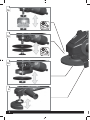
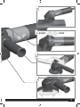
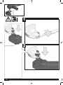
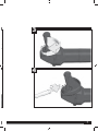
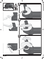
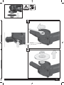
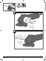
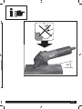
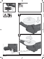
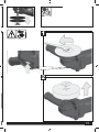
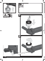
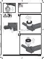
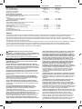
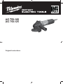
AG 750-100 750-115 AG 750-125 Original Instructions 414 032 - AG750-115.indd 1 26.11.2009 12:58:30 2 2 3 3 16 14 10 6 4 414 032 - AG750-115.indd 4 4 26.11.2009 12:58:31 414 :58:31 13 9 START STOP 12 8 5 414 032 - AG750-115.indd 5 5 26.11.2009 12:58:31 1 For Separating! For Trennarbeiten! cutting off operation! Für For cutting work! Pour les travaux de tronçonnage! Per lavori di separazione! ¡Para trabajos de tronzado! Para trabalhos de corte! Voor doorslijpwerkzaamheden! Til skærearbejder! For kutting! För kapningsarbeten! Katkaisutöihin! īȚĮ İȡȖĮıȓİȢ țȠʌȒȢ! AyÕrma iúleri için! Pro Ĝezací práce! Pre rezacie práce! Do robót związanych z rozcinaniem! Vágási munkálatokhoz! Za razdvajalna dela! Za odvajaþke radove! Griešanai! Pjovimo darbams! Lõiketöödeks! Ⱦɥɹ ɪɚɛɨɬ ɩɨ ɪɚɡɞɟɥɟɧɢɸ! Ɂɚ ɪɹɡɚɧɟ (ɪɚɡɞɟɥɹɧɟ)! Pentru lucrӽri de retezare! Ɂɚ ɪɚɛɨɬɢ ɫɨ ɞɟɥɟʃɟ! 䢠Ա֊໊ՠ܂Μ 6 414 032 - AG750-115.indd 6 2 6 26.11.2009 12:58:31 414 :58:31 3 4 7 414 032 - AG750-115.indd 7 7 26.11.2009 12:58:31 A B C 8 414 032 - AG750-115.indd 8 8 26.11.2009 12:58:31 414 :58:31 START STOP START/LOCK 2 1 STOP 1 2 9 414 032 - AG750-115.indd 9 9 26.11.2009 12:58:31 1 < 5 mm > 5 mm 2 10 414 032 - AG750-115.indd 10 10 26.11.2009 12:58:31 414 :58:31 1 2 11 414 032 - AG750-115.indd 11 11 26.11.2009 12:58:32 1 2 12 414 032 - AG750-115.indd 12 12 26.11.2009 12:58:32 414 :58:32 30° 13 414 032 - AG750-115.indd 13 13 26.11.2009 12:58:32 Accessory Zubehör Accessoire Accessorio Accessorio Acessório Toebehoren Tilbehør Tilbehør Tillbehör Lisälaite ÅîáñôÞìáôá Aksesuar PĜíslušenství Príslušenstvo Element wyposaĪenia dodatkowego Tartozék Oprema Pribor Papildus aprƯkojums Priedas Tarvikud Äîïîëíèòåëü Ⱥɤɫɟɫɨɚɪ Accesorii Ⱦɨɞɚɬɨɰɢ ٙ 1 2 14 414 032 - AG750-115.indd 14 14 26.11.2009 12:58:32 414 :58:32 Accessory Zubehör Accessoire Accessorio Accessorio Acessório Toebehoren Tilbehør Tilbehør Tillbehör Lisälaite ÅîáñôÞìáôá Aksesuar PĜíslušenství Príslušenstvo Element wyposaĪenia dodatkowego Tartozék Oprema Pribor Papildus aprƯkojums Priedas Tarvikud Äîïîëíèòåëü Ⱥɤɫɟɫɨɚɪ Accesorii Ⱦɨɞɚɬɨɰɢ ٙ 1 2 15 414 032 - AG750-115.indd 15 15 26.11.2009 12:58:32 Accessory Zubehör Accessoire Accessorio Accessorio Acessório Toebehoren Tilbehør Tilbehør Tillbehör Lisälaite ÅîáñôÞìáôá Aksesuar PĜíslušenství Príslušenstvo Element wyposaĪenia dodatkowego Tartozék Oprema Pribor Papildus aprƯkojums Priedas Tarvikud Äîïîëíèòåëü Ⱥɤɫɟɫɨɚɪ Accesorii Ⱦɨɞɚɬɨɰɢ ٙ 1 2 16 414 032 - AG750-115.indd 16 16 26.11.2009 12:58:32 414 :58:32 Accessory Zubehör Accessoire Accessorio Accessorio Acessório Toebehoren Tilbehør Tilbehør Tillbehör Lisälaite ÅîáñôÞìáôá Aksesuar PĜíslušenství Príslušenstvo Element wyposaĪenia dodatkowego Tartozék Oprema Pribor Papildus aprƯkojums Priedas Tarvikud Äîïîëíèòåëü Ⱥɤɫɟɫɨɚɪ Accesorii Ⱦɨɞɚɬɨɰɢ ٙ 1 2 17 414 032 - AG750-115.indd 17 17 26.11.2009 12:58:32 TECHNICAL DATA 750-115 AG 750-125 AG 750-100 Rated input ................................................................................. .......... 750 W ......................... 750 W Max. no-load speed .................................................................... ...... 10000 (min-1)............... 10000 (min-1) Grinding disk diameter................................................................ ...........115 ...........100 mm....................... 125 mm Thread of work spindle .............................................................. ........ M 10 14 ........................... M 14 Weight without cable .................................................................. ........... 1,8 kg .......................... 1,8 kg Noise/Vibration Information Measured values determined according to EN 60745.Typically, the A-weighted noise levels of the tool are: Sound pressure level (K = 3 dB(A)) .......................................... ............ ......... 87,1 82 dB(A) .................. 87,1 dB(A) Sound power level (K = 3 dB(A)) .............................................. ............ ......... 98,1 93 dB(A) .................. 98,1 dB(A) Wear ear protection! Total vibration values (vector sum in the three axes) determined according to EN 60745: Surface grinding: vibration emission value ah ............................ ........... 6,8 m/s2....................... 6,8 m/s2 Uncertainty K = ........................................................................... ........... 1,5 m/s2....................... 1,5 m/s2 Disk sanding vibration emission value ah ................................... ........... 3,5 m/s2....................... 3,5 m/s2 Uncertainty K = ........................................................................... ........... 1,5 m/s2....................... 1,5 m/s2 For other applications, e.g. Abrasive Cutting-Off Operations or Wire Brushing other vibration values could occure. WARNING The vibration emission level given in this information sheet has been measured in accordance with a standardised test given in EN 60745 and may be used to compare one tool with another. It may be used for a preliminary assessment of exposure. The declared vibration emission level represents the main applications of the tool. However if the tool is used for different applications, with different accessories or poorly maintained, the vibration emission may differ. This may signi¿cantly increase the exposure level over the total working period. An estimation of the level of exposure to vibration should also take into account the times when the tool is switched off or when it is running but not actually doing the job. This may signi¿cantly reduce the exposure level over the total working period. Identify additional safety measures to protect the operator from the effects of vibration such as: maintain the tool and the accessories, keep the hands warm, organisation of work patterns. and cracks, backing pad for cracks, tear or excess wear, wire brush for loose or cracked wires. If power tool or accessory is dropped, inspect for damage or install an undamaged accessory. After inspecting and installing an accessory, position yourself and bystanders away from the plane of the rotating accessory and run the power tool at maximum no-load speed for one minute. Damaged accessories will normally break apart during this test time. h) Wear personal protective equipment. Depending on application, use face shield, safety goggles or safety glasses. As appropriate, wear dust mask, hearing protectors, gloves and shop apron capable of stopping small abrasive or workpiece fragments. The eye protection must be capable of stopping Àying debris generated by various operations. The dust mask or respirator must be capable of ¿ltrating particles generated by your operation. Prolonged exposure to high intensity noise may cause hearing loss. i) Keep bystanders a safe distance away from work area. Anyone entering the work area must wear personal protective equipment. Fragments of workpiece or of a broken accessory may Ày away and cause injury beyond immediate area of operation. j) Hold power tool by insulated gripping surfaces only, when performing an operation where the cutting accessory may contact hidden wiring or its own cord. Cutting accessory contacting a „live“ wire may make exposed metal parts of the power tool „live“ and shock the operator. k) Position the cord clear of the spinning accessory. If you lose control, the cord may be cut or snagged and your hand or arm may be pulled into the spinning accessory. l) Never lay the power tool down until the accessory has come to a complete stop. The spinning accessory may grab the surface and pull the power tool out of your control. m) Do not run the power tool while carrying it at your side. Accidental contact with the spinning accessory could snag your clothing, pulling the accessory into your body. n) Regularly clean the power tool’s air vents. The motor’s fan will draw the dust inside the housing and excessive WARNING! Read all safety warnings and all instructions, including those given in the accompanying brochure. Failure to follow the warnings and instructions may result in electric shock, ¿re and/or serious injury. Save all warnings and instructions for future reference. SAFETY INSTRUCTIONS Safety Safety Warnings Warnings Common Common for for Grinding, Grinding, Sanding, Sanding, Wire Wire Abrasive Cutting-Off Operations: Brushing Brushing or Operations: a) This power tool is intended to function as a grinder, a) This power tool isorintended to function a grinder, sander, wire brush, cut-off tool. Read allassafety sander, wire brush. Read all safety warnings, instructions, warnings, instructions, illustrations and speci¿ cations illustrations and specifications provided with all this power provided with this power tool. Failure to follow tool. Failurelisted to follow all may instructions below may¿re result instructions below result inlisted electric shock, and/in electric shock, fire and/or serious injury. or serious injury. b) Operations as polishing are not recommended to be performed with this power tool. Operations for which the power tool was not designed may create a hazard and cause personal injury. c) Do not use accessories which are not speci¿cally designed and recommended by the tool manufacturer. Just because the accessory can be attached to your power tool, it does not assure safe operation. d) The rated speed of the accessory must be at least equal to the maximum speed marked on the power tool. Accessories running faster than their rated speed can break and Ày apart. e) The outside diameter and the thickness of your accessory must be within the capacity rating of your power tool. Incorrectly sized accessories cannot be adequately guarded or controlled. f) The arbour size of wheels, Àanges, backing pads or any other accessory must properly ¿t the spindle of the power tool. Accessories with arbour holes that do not match the mounting hardware of the power tool will run out of balance, vibrate excessively and may cause loss of control. g) Do not use a damaged accessory. Before each use inspect the accessory such as abrasive wheels for chips 18 414 032 - AG750-115.indd 18 S 18 26.11.2009 12:58:32 414 :58:32 Additional SafetySpeci¿ Warnings c for Abrasive Safety Warnings c forSpeci¿ Sanding Operations: Cutting-Off Operations: a) Do not use excessively oversized sanding disc paper. a) Do not “jam” the cut-off wheel or apply when excessive Follow manufacturers recommendations, selecting pressure. Do not attempt to make anextending excessive depththe of sanding paper. Larger sanding paper beyond cut. Overstressing theawheel increases theand loading and sanding pad presents laceration hazard may cause susceptibility to twisting binding of the wheel in the cut and snagging, tearing of the or disc or kickback. the possibility of kickback or wheel breakage. b) Do not positionSpeci¿ your body in line with andOperations: behind the Safety Warnings c for Wire Brushing rotating wheel. When the wheel, at the point of operation, is a) Be aware are thrownkickback by the brush moving awaythat fromwire yourbristles body, the possible may even during ordinary operation. Do nottool overstress propel the spinning wheel and the power directly atthe you. wires by applying excessive load to the brush. The wire c) Whencan wheel is penetrate binding or when interrupting a cut for bristles easily light clothing and/or skin. any reason, switch off the power tool and hold the power b) If motionless the use of auntil guard iswheel recommended wire tool the comes tofor a complete stop. brushing, do not allow any interference of the Never attempt to remove the cut-off wheel fromwire thewheel cut or brush with the guard. Wire wheel or brush may expand in while the wheel is in motion otherwise kickback may diameter due to work centrifugal forces. occur. Investigate andload takeand corrective action to eliminate the cause of wheel binding. d) Do not restart cutting operation in the workpiece. Appliances used atthe many different locations including open air Let thebe wheel reach via fullaspeed and carefully reenter should connected residual current device of 30 the mA or cut. less.The wheel may bind, walk up or kickback if the power tool is restarted in the workpiece. Dust and splinters must not be removed while the machine is e) Support panels or any oversized workpiece to running. minimize thewhen risk machine of wheelispinching Only plug-in switchedand off. kickback. Large workpieces tend to sag under their own weight. Supports Never reach into the danger area of the tool it is must be placed under the workpiece near thewhen line of cut and running. near the edge of the workpiece on both sides of the wheel. Always use the auxiliary handle. f) Use extra caution when making a “pocket cut” into existing walls or other blind areas. wheel Immediately switch off the machine in The caseprotruding of considerable may cut gas watermalfunctions pipes, electrical wiring or objects that in vibrations or or if other occur. Check the machine can kickback. ordercause to ¿nd out the cause. Always use and store the grinding disks according to the manufacturer's instructions. Safety Warnings Speci¿c for Sanding Operations: When grinding metal, Àying sparks are produced. Takepaper. care a) Do not use excessively oversized sanding disc that no persons are endangered. Because of when the danger of Follow manufacturers recommendations, selecting ¿re, no combustible materials should located inbeyond the vicinity sanding paper. Larger sanding paperbeextending the (spark À ight zone). Do not use dust extraction. sanding pad presents a laceration hazard and may cause snagging, tearingbe of taken the disc orno kickback. Due care should that sparks or sanding dust Àying from the workpiece come into contact with you. When separating stone the guide shoe must beOperations: used! Safety Warnings Speci¿c for Wire Brushing The nut wire must bristles be tightened before starting to work a) Beadjusting aware that are thrown by the brush with the machine. even during ordinary operation. Do not overstress the wires by applying to the brush. Thetowire The workpiece mustexcessive be ¿xed if load it is not heavy enough be bristles can easily light clothing and/or disk skin.with steady. Never leadpenetrate the workpiece to the grinding your hand. b) If the use of a guard is recommended for wire brushing, do not allow any interference of themetals wire wheel Under extreme conditions (e.g. smooth-grinding with or guard. Wire wheel orwheel), brush may expand thebrush arbourwith and the vulcanized ¿bre grinding signi¿ cant in diameter due tocan work load centrifugal contamination build upand on the inside offorces. the angle grinder. 26.11.2009 For safety reasons, in such conditions the inside should be12:58:32 cleaned thoroughly of metal deposits and a motor circuitAppliances used at many different locations including open air breaker must be connected in series. If the motor circuitshould connected via amust residual current device of 30 mA or breakerbe trips the machine be sent for repair. less. For accessories intended to be ¿tted with threaded hole Dust and splinters not beinremoved while the enough machinetois wheel, ensure that must the thread the wheel is long running. accept the spindle length. Only plug-inorwhen machine off. For cutting separating useisaswitched closed protection cap, Never reach intoaccessory. the danger area of the tool when it is available as an running. SPECIFIED CONDITIONS OF USE Always use the auxiliary handle. The angle grinder to cut many rough-grind different Immediately switchcan off be theused machine inand caserough-grind of many considerable different e.g. grinding with a vibrations or if other malfunctions occur.for Check machine in materials,materials, e.g. metal or metal stone,or forstone, grinding with athe plastic plastic plate and for operation wire brush. order togrinding ¿plate nd out theforcause. grinding and operation with thewith wirethe brush. Always use follow thestore manufacturer’s if youtoare Always and the grindinginstructions disks according the unsure about anything to do with the machine.. machine. manufacturer's instructions. Do not use this product in any other way as stated for When grinding metal, Àying sparks are produced. Takenormal care use. no persons are endangered. Because of the danger of that ¿re, no combustible materials should be located in the vicinity (spark Àight zone). Do not use dust extraction. Due care should be taken that no sparks or sanding dust Àying from the workpiece come into contact with you. When separating stone the guide shoe must be used! The adjusting nut must be tightened before starting to work with the machine. accumulation of powdered metal may cause electrical hazards. o) Do not operate the power tool near Àammable materials. Sparks could ignite these materials. p) Do not use accessories that require liquid coolants. Using water or other liquid coolants may result in electrocution or shock. Kickback and Related Warnings Kickback is a sudden reaction to a pinched or snagged rotating wheel, backing pad, brush or any other accessory. Pinching or snagging causes rapid stalling of the rotating accessory which in turn causes the uncontrolled power tool to be forced in the direction opposite of the accessory’s rotation at the point of the binding. For example, if an abrasive wheel is snagged or pinched by the workpiece, the edge of the wheel that is entering into the pinch point can dig into the surface of the material causing the wheel to climb out or kick out. The wheel may either jump toward or away from the operator, depending on direction of the wheel’s movement at the point of pinching. Abrasive wheels may also break under these conditions. Kickback is the result of power tool misuse and/or incorrect operating procedures or conditions and can be avoided by taking proper precautions as given below. a) Maintain a ¿rm grip on the power tool and position your body and arm to allow you to resist kickback forces. Always use auxiliary handle, if provided, for maximum control over kickback or torque reaction during start-up. The operator can control torque reactions or kickback forces, if proper precautions are taken. b) Never place your hand near the rotating accessory. Accessory may kickback over your hand. c) Do not position your body in the area where power tool will move if kickback occurs. Kickback will propel the tool in direction opposite to the wheel’s movement at the point of snagging. d) Use special care when working corners, sharp edges etc. Avoid bouncing and snagging the accessory. Corners, sharp edges or bouncing have a tendency to snag the rotating accessory and cause loss of control or kickback. e) Do not attach a saw chain, woodcarving blade or toothed saw blade. Such blades create frequent kickback and loss of control. Safety Warnings Speci¿c for Grinding and Abrasive Safety Warnings Specific for Grinding Operations: Cutting-Off Operations: a) Use only wheel types that are recommended for your 414 032 AG750-115.indd 19 c guard designed for the power tool and the speci¿ selected wheel. Wheels for which the power tool was not designed cannot be adequately guarded and are unsafe. b) The guard must be securely attached to the power tool and positioned for maximum safety, so the least amount of wheel is exposed towards the operator. The guard helps to protect operator from broken wheel fragments and accidental contact with wheel. c) Wheels must be used only for recommended applications. For example: do not grind with the side of cut-off wheel. Abrasive cut-off wheels are intended for peripheral grinding, side forces applied to these wheels may cause them to shatter. d) Always use undamaged wheel Àanges that are of correct size and shape for your selected wheel. Proper wheel Àanges support the wheel thus reducing the possibility of wheel breakage. Flanges for cut-off wheels may be different from grinding wheel Àanges. e) Do not use worn down wheels from larger power tools. Wheel intended for larger power tool is not suitable for the higher speed of a smaller tool and may burst. 19 414 032 - AG750-115.indd 19 19 26.11.2009 12:58:32 MAINS CONNECTION The workpiece must be ¿xed if it is not heavy enough to be steady. lead the workpiece the grinding disk with ConnectNever only to single-phase a.c. to current and only to the your hand. system voltage indicated on the rating plate. It is also possible Under extreme conditions (e.g. to connect to sockets without ansmooth-grinding earthing contactmetals as thewith the arbour and vulcanized ¿bre grinding wheel), signi¿cant design conforms to safety class II. contamination can build up on the inside of the angle grinder. For safety reasons, in such conditions the inside should be MAINTENANCE cleaned thoroughly of metal deposits and a motor circuitThe ventilation of the machine bemotor kept clear at all breaker must beslots connected in series.must If the circuittimes. trips the machine must be sent for repair. breaker Useaccessories only Milwaukee accessories andwith spare parts. Should For intended to be ¿tted threaded hole components exchanged not been to wheel, ensureneed that to thebethread in the which wheel have is long enough described, please contact one of our Milwaukee service accept the spindle length. agents (see our list of guarantee/service addresses). For cutting or separating use a closed protection cap, If needed,as anan exploded view of the tool can be ordered. available accessory. Please state the ten-digit No. as well as the machine type printed on the label and order drawing at your local SPECIFIED CONDITIONS OFthe USE service agents or directly at: Milwaukee Electric Tool, The angle grinder10, canD-71364 be used Winnenden, to cut and rough-grind Max-Eyth-Straße Germany. many different materials, e.g. metal or stone, for grinding with a plastic grinding plate and for operation with the wire brush. Always follow the manufacturer’s instructions if you are unsure about anything to do with the machine.. Do not use this product in any other way as stated for normal use. SYMBOLS Please read the instructions carefully before starting the machine. Always wear goggles when using the machine. Always disconnect the plug from the socket before carrying out any work on the machine. Accessory - Not included in standard equipment, available as an accessory. Do not dispose of electric tools together with household waste material! In observance of European Directive 2002/96/EC on waste electrical and electronic equipment and its implementation in accordance with national law, electric tools that have reached the end of their life must be collected separately and returned to an environmentally compatible recycling facility. EC-DECLARATION OF CONFORMITY We declare under our sole responsibility that this product is in conformity with the following standards or standardized documents. EN 60745, EN 55014-1, EN 55014-2, EN 610003-2, EN 61000-3-3, in accordance with the regulations 98/37/ EC, 2004/108/EC Winnenden, 2009-10-05 Rainer Kumpf Manager Product Development MAINS CONNECTION Connect only to single-phase a.c. current and only to the system voltage indicated on the rating plate. It is also possible to connect to sockets without an earthing contact as the design conforms to safety class II. MAINTENANCE 414 032 - AG750-115.indd 20 machine must be kept clear at all The ventilation slots of the 26.11.2009 12:58:32 times. Use only Milwaukee accessories and spare parts. Should components need to be exchanged which have not been described, please contact one of our Milwaukee service agents (see our list of guarantee/service addresses). If needed, an exploded view of the tool can be ordered. Please state the ten-digit No. as well as the machine type printed on the label and order the drawing at your local service agents or directly at: Milwaukee Electric Tool, Max-Eyth-Straße 10, D-71364 Winnenden, Germany. 20 414 032 - AG750-115.indd 20 20 26.11.2009 12:58:32 :58:32 Made in China Copyright 2009 Milwaukee Electric Tool Max-Eyth-Straße 10 D-71364 Winnenden Germany +49 (0) 7195-12-0 414 032 - AG750-115.indd 100 (11.09) 4931 4140 32 26.11.2009 12:58:36