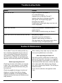
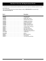
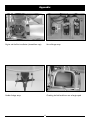
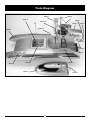
1
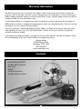
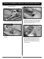
.46-Size Nitro Powered Air Boat Owner's Manual Specifications Length .................................................................................................31 in (787mm) Beam ...................................................................................................15 in (381mm) Engine ...................................................................................... Evolution .46 (7.6cc) Radio System ...........................................................Pro Boat AM 27MHz 2-Stick Introduction Congratulations on the purchase of your Pro Boat™ Vortex 46 Airboat. You are just minutes from one of the most thrilling experiences that the radio control hobby has to offer. The Pro Boat Vortex 46 is a professionally built, ready-to-run fiberglass Airboat model. Powered by the potent Evolution 46 engine, you will be able to race across the water and enjoy the unique thrill of airboat performance. Read this owner’s manual thoroughly. You also need to read the included Evolution 46 engine manual, along with the Pro Boat radio system manual. It is very important that you operate this boat responsibly. With proper care and maintenance, you will be able to enjoy your Vortex 46 for many years to come. Carefully unpack Vortex 46 and examine the boat and its contents. The box should contain the Vortex 46 RTR with radio installed, a boat stand, and the Pro Boat radio transmitter. If you are missing any of these items or notice any damage, immediately contact the place of purchase. Warning This boat is not a toy! It is a high performance RC model boat. Do Not take risks that could endanger you or others. Before operating your model, make sure your frequency is clear. If someone else is operating on the same frequency, both models could go out of control, possibly causing damage to the models, as well as to others. Be certain to check all of the hardware, exhaust system, and propeller, making sure that all are secure before and after each run. Always stay clear of the propeller when the engine is running! When you first begin to run your Vortex 46, place in water with the engine running at approximately 1/8 throttle. Slowly increase the throttle until boat accelerates onto plane. Gradually increase throttle to no more than 1/2 until you become more familiar with the boat. When operating this model, stay clear of people, full-sized boats, stationary objects, and wildlife. Also, watch out for fishing lines that could get tangled in the propeller and rudder. It is preferable to operate the Pro Boat Vortex 46 only in calm water. We also suggest that you do not run the Vortex 46 in salt water. If at any time while operating your Vortex 46 you sense any abnormal function, end your operation immediately. Do not operate your Vortex 46 again until you are certain the problem has been corrected. Service Center Information If you have any questions regarding the Pro Boat Vortex 46, please contact the Horizon Service Center: Horizon Service Center 4105 Fieldstone Rd. Champaign, IL 61822 1-877-504-0233 2 Table of Contents Introduction ................................................................................................................................ 2 Warning ...................................................................................................................................... 2 Table of Contents ....................................................................................................................... 3 Additional Required Items ........................................................................................................ 3 Suggested Field Equipment and Supplies ............................................................................... 3 Warranty Information ............................................................................................................... 4 Contents...................................................................................................................................... 4 Section 1: Building the Boat Stand .......................................................................................... 5 Section 2: Rudder Installation ................................................................................................... 5 Section 3: Installation of Receiver and Transmitter Batteries .............................................. 6 Section 4: Range Checking the Pro Boat Radio System........................................................ 7 Section 5: Evolution Power System.......................................................................................... 8 Section 6: Starting the Evolution Engine ................................................................................ 9 Section 7: Engine Adjustments ............................................................................................... 10 Troubleshooting Guide ............................................................................................................ 11 Section 8: Maintenance............................................................................................................ 11 Section 9: Vortex 46 Replacement Parts ............................................................................... 12 Appendix ................................................................................................................................... 13 Parts Diagram .......................................................................................................................... 14 Notes ......................................................................................................................................... 15 Additional Required Items Although the Vortex 46 comes fully assembled and ready for action, you will need a few tools to get you ready to run your boat. You will need the following: Blue Thunder™ 20% Fuel (quart) (DYN2320) Manual Fuel Pump (HAN118) Glow Plug Wrench (DYN2510) Ni-Cd Glow Driver (DYN1925) 12 “AA” alkaline batteries (8 for the transmitter and 4 for the receiver) Clear tape to seal radio box Suggested Field Equipment and Supplies In addition to the items needed to run the Vortex 46, we recommend that you carry the following in your field box: Engine Tuning Screwdriver (DYN2775) Clean towels Replacement Glow Plugs (HAN3006) “AA” alkaline batteries Hex driver/Allen wrench (2.5mm, 4mm) Adjustable wrench (small) #1 and #2 Phillips Screwdriver Extra Propellers (EVOE100P) 3 Warranty Information Pro Boat™ guarantees this kit to be free from defects in both material and workmanship at the date of purchase. This warranty does not cover any parts damaged by use or modification. In no case shall Horizon Hobby’s liability exceed the original cost of the purchased kit. Further, Horizon Hobby reserves the right to change or modify this warranty without notice. In that Horizon Hobby has no control over the final assembly, or material used for the final assembly, no liability shall be assumed or accepted for any damage of the final user-assembled product. By the act of using the product, the user accepts all resulting liability. All warranty questions should be directed to Horizon Hobby, Inc. Please do not contact your local hobby shop regarding warranty issues. This will enable Horizon to better answer your questions and provide service if assistance is needed. If not prepared to accept the liability associated with the use of this product, the buyer is advised to return this kit immediately, in new and unused condition, to the place of purchase. Horizon Hobby 4105 Fieldstone Road Champaign, Illinois 61822 (877) 504-0233 www.horizonhobby.com Contents • Assembled Vortex 46 RTR • Pro Boat radio transmitter • Boat stand • Rudder • Evolution instructions • Pro Boat radio instructions 4 Section 1: Building the Boat Stand 1. There are 4 plywood pieces. The 2 short plywood pieces are the ends of the boat stand. 2. Attach the 2 long plywood pieces of the interlocking boat stand to one end of the short plywood pieces. Repeat with the remaining short plywood pieces. 3. Secure the interlocking boat stand with thick CA or Epoxy. Section 2: Rudder Installation Parts Needed Rudder Phillips rudder mounting screw 1. Locate the rudder and the Phillips rudder mounting Screw. 2. Carefully insert the rudder shaft into the bottom of the rudder strut and through the control arm. 3. Find the predrilled hole in the rudder shaft. Using a #1 Phillips screwdriver, tighten the screw as shown. 5 Section 3: Installation of Receiver and Transmitter Batteries Receiver Batteries 3. Remove the dry cell battery holder from the radio box and unwrap the foam from around the dry cell battery holder. Install 4 “AA” alkaline batteries as shown. Note the proper polarity. Wrap the battery box in foam. 1. Remove the knurled aluminum nut that secures the cockpit. Pull the cockpit off the boat. 2. Remove the clear lid that covers the radio box. 4. Re-install the battery holder into the radio box and properly seal the radio box with clear tape. Failure to properly seal the radio box could result in damage to your radio equipment. Insert the receiver antenna tube into the clear lid. 6 Section 3: Receiver and Transmitter Batteries (cont) Transmitter Batteries 1. Remove the transmitter from the box. 5. Turn on the receiver by pulling up on the receiver switch harness lever. Move the throttle stick forward and confirm that the throttle barrel opens. Move the rudder stick left and right, confirming that the rudder is centered with the steering gimbal at rest and that the reversing switches are in the correct position. 2. Remove the battery cover on the bottom of the transmitter. 3. Note the proper polarity and insert 8 “AA” batteries into the transmitter. 6. To keep the boat from receiving stray signals the transmitter should be turned on first, followed by the receiver. Likewise, the boat should be turned off first before the transmitter. 4. Turn on the radio and confirm that all LEDs illuminate, indicating proper installation of fresh batteries. Section 4: Range Checking the Pro Boat Radio System Before the first run of the Vortex 46, you should check the radio for proper operation and to ensure proper control movement of the rudder and throttle. Also ensure that the antenna on the boat is extended properly and that all batteries are in working condition. 3. If everything appears to be operating correctly, raise the transmitter antenna and start the engine (refer to Section 6 of this manual and to the separate Evolution .46 engine manual). Place the boat in the water and run it (at about 1/3 throttle) close to the shoreline. If the radio system is operating properly, you can begin to run the boat faster and further away from the shoreline. 1. With the radio system turned on (transmitter then receiver) and the transmitter antenna down (engine off), walk off 40 to 50 paces from the Vortex 46. Note: It is a good idea to range check prior to operating your boat after any repair, installation of new batteries, or at the beginning of each boating season. 2. Have an assistant remain with the boat to check for proper control movement of the rudder from your transmitter input. 7 Section 5: Evolution Power System The Evolution Power System has been specifically designed with the first-time modeler in mind. The engine and special three blade propeller have been designed to give your Vortex 46 optimum performance. The engine is designed for easy starting and reliable idle to give you confidence in your equipment, allowing you to concentrate on developing your boating skills. • Only use a “Start Stick” or electric starter to start the engine. Benefits of the Evolution Power System • Lower noise level than standard 10 x 6 prop, baffle in muffler lowers noise even more. • Pre-set needle settings—ready-to-run out of the box. • Only make adjustments to the carburetor from behind the engine. • Needle valve limiters make it impossible for beginners to adjust the needles valves wrong to the point that the engine will not run. • Keep spectators at least 20 feet away and out of the path of a rotating propeller. • User-friendly—easy to start from first try with super reliable idle and no break-in needed. • Wear safety glasses and hand protection when operating model engines. Do not permit any objects to touch a turning propeller. Remain clear of the propeller's plane of rotation. Warning: Before operating your engine, read and follow all safety points. A rotating propeller can cause serious personal injury. • To stop the engine, cut off the fuel and air supply by moving the throttle stick and trim lever down to close the carburetor. Do not stop the propeller with your hand or other object. Follow these instructions carefully! If this is the first time you have run a model airplane engine, we recommend that you seek the help of an experienced modeler. Your local hobby shop can put you in contact with an RC boating club in your area. • Inspect the propeller after each run; discard any propeller that has nicks, scratches or any other visible defect. Do not repair, alter or in any way modify a propeller. Replacement propellers are available through your local hobby retailer. 8 Section 6: Starting the Evolution Engine Field Equipment Required The following are included in the Hangar 9® StartUp Field Accessory Pack (HANSTART) • Sturdy cardboard construction tote box • Manual fuel pump • Hangar 9 glow plugs (2) • 4-way wrench • Rechargeable glow driver with charger • Start stick 2. To prime your engine, first turn on your transmitter and then your receiver. Move the throttle to full open and place your finger over the carburetor opening. Turn the propeller over by hand until you can see fuel entering the fuel line. Move the throttle stick full down to idle. Other Items Required (not included in Start-Up Field Accessory Pack) • Fuel, 20% nitro content (Blue Thunder recommended) • Electric starter (optional) 1. Fill the fuel tank with the proper fuel. We recommend 20% Blue Thunder fuel. Fill the tank by connecting the fuel pump to the line that has the fuel plug bolt installed in the end of the tubing. Disconnect the fuel line attached to the pressure fitting of the muffler; your tank is full when fuel begins to run out of the pressure line. Reconnect the fuel lines to the needle valve assembly and muffler. Caution: Always have a helper hold your boat when starting the engine. Note: It is very important to reconnect the lines to the correct place. If they are reconnected incorrectly, the engine will not run properly. 3. Move the throttle to the low position and the throttle trim lever to the middle position. Place the glow driver on the glow plug and, using a start stick, turn the propeller counter clockwise through the compression stroke. You should feel a “bump” against the start stick. When you feel the “bump”, flip the propeller counter clockwise to start the engine. Repeat the process if the engine does not start. 9 Section 7: Engine Adjustments Fine-Tuning the High-Speed Needle Start your engine and advance the throttle to full, then pinch the fuel line going to the engine. If the engine dies immediately without an increase in rpm, the setting is too lean. Adjust the high-speed needle valve counterclockwise (out) 1/2 turn and repeat the test. When the high-speed needle is adjusted correctly, the engine should increase rpm slightly and then quit. If the engine rpm increases more than 200–300 rpm and continues to run, the needle valve setting is too rich. Adjust the needle valve clockwise (in) 1/8th of a turn and repeat the test until the engine responds correctly to the pinch test. Model engines run on a mixture of fuel and air. The high-speed and low-speed needle valves control the ratio of fuel to air that the engine receives. If you find that small adjustments are needed, have an experienced modeler help you to fine-tune your engine. Do not attempt to move the needles past the preset stops. High-Speed Needle Adjustment Fine-Tuning the Low-Speed Needle After fine-tuning the high-speed needle, you can begin to test the low-speed needle. Start your engine and go to full throttle for approximately 5–10 seconds then return to idle. Pinch the fuel line going to the engine. If the engine dies immediately without an increase in rpm, the setting is too lean. Adjust the needle valve counterclockwise (out) 1/8th of a turn and repeat the test. When the low-speed needle is adjusted correctly, the engine should increase rpm slightly and then quit. If the engine rpm increases more than 200–300 rpm and continues to run, the needle-valve setting is too rich. Adjust the needle valve clockwise (in) 1/16th of a turn and repeat the test until the engine responds correctly to the pinch test. Low-Speed Needle Adjustment Warning: Make all adjustments to the Evolution engine’s lowspeed needle valve with the engine stopped. Our technicians have preset the needle valves of the Evolution engine. Your engine should run properly at these preset needle settings. On occasion, depending on your location, you may find it necessary to adjust the high-speed and lowspeed needle valves to optimize the performance of your engine. The needle valves have limiters to allow small adjustments to the engine. The lowspeed needle valve limiter allows 1/4 turn of the needle valve, turning clockwise (in) will lean the mixture while turning counterclockwise (out) will richen the mixture to the low-speed or idle setting of the engine. The high-speed needle valve limiter allows one full turn of the needle valve. As with the low-speed adjustment, turning the high-speed needle valve clockwise (in) will lean the mixture, while turning counterclockwise (out) will richen the mixture of the high-speed setting of the engine. 10 Troubleshooting Guide Problem Solution Engine will not start Engine is not primed: See Section 6 Out of fuel: fill fuel tank Improper fuel: use 20% Blue Thunder™ Improper glow plug: install proper glow plug Glow igniter not charged: charge igniter Dead glow plug: replace Flooded engine: remove glow plug, invert boat and rotate the propeller Engine starts, then dies Pressure line blocked or unhooked: connect or replace fuel line Reset needles to baseline setting: see Section 6 Engine starts and runs for several minutes, then dies Bad glow plug: replace Idle speed set too low: see Section 6 Improper needle settings: see Section 6 Glow plug failed due to lean engine setting: richen carburetor settings and replace glow plug Section 8: Maintenance When refueling, always wipe away any excess fuel that may have spilled into or on the boat. The Pro Boat™ Vortex 46 should provide many hours of exciting high-speed racing fun with just minor maintenance. Preventative maintenance is very important. Taking the time to ensure that all the set screws and bolts are tight before each operation of the boat will prevent many problems. After operating the Vortex 46 Wipe off any exhaust residue from the boat. If you operate the Vortex 46 in salt water, it is suggested that you thoroughly rinse the deck, hull, and all the metal hardware with fresh water, and then dry them with a clean towel. After cleaning, coat all metal parts with a silicone spray lubricant. This will help to prevent corrosion. Before operating Vortex 46 Check that all screws and hardware are securely in place. This is very important, as the manifold screws will occasionally vibrate loose during the first initial runs. Ensure that the radio box and equipment inside is dry. Check the propeller for damage in the form of chipping or cracking. If you find any damage, replace the propeller, as the damage will affect the performance of the boat and could also cause safety concerns. 11 Section 9: Vortex 46 Replacement Parts In the event that you need to purchase replacement parts for your engine or the Vortex 46 please see your local hobby store. You can also purchase them from Horizon Hobby by calling 1-800-338-4639 or shop online @ www.horizonhobby.com Part # Description PRB2701 . . . . . . . . . . . . . . . . . . . . . . . . . . . . . . . . . . . . . . . PRB2702 . . . . . . . . . . . . . . . . . . . . . . . . . . . . . . . . . . . . . . . PRB2703 . . . . . . . . . . . . . . . . . . . . . . . . . . . . . . . . . . . . . . . PRB2704 . . . . . . . . . . . . . . . . . . . . . . . . . . . . . . . . . . . . . . . PRB2705 . . . . . . . . . . . . . . . . . . . . . . . . . . . . . . . . . . . . . . . PRB2706 . . . . . . . . . . . . . . . . . . . . . . . . . . . . . . . . . . . . . . . PRB2707 . . . . . . . . . . . . . . . . . . . . . . . . . . . . . . . . . . . . . . . PRB2708 . . . . . . . . . . . . . . . . . . . . . . . . . . . . . . . . . . . . . . . PRB2709 . . . . . . . . . . . . . . . . . . . . . . . . . . . . . . . . . . . . . . . PRB2710 . . . . . . . . . . . . . . . . . . . . . . . . . . . . . . . . . . . . . . . PRB2711 . . . . . . . . . . . . . . . . . . . . . . . . . . . . . . . . . . . . . . . PRB2712 . . . . . . . . . . . . . . . . . . . . . . . . . . . . . . . . . . . . . . . PRB2713 . . . . . . . . . . . . . . . . . . . . . . . . . . . . . . . . . . . . . . . PRB2714 . . . . . . . . . . . . . . . . . . . . . . . . . . . . . . . . . . . . . . . EVOE100P . . . . . . . . . . . . . . . . . . . . . . . . . . . . . . . . . . . . . EVOE100S . . . . . . . . . . . . . . . . . . . . . . . . . . . . . . . . . . . . . PRB2715 . . . . . . . . . . . . . . . . . . . . . . . . . . . . . . . . . . . . . . . PRB2716 . . . . . . . . . . . . . . . . . . . . . . . . . . . . . . . . . . . . . . . PRB2717 . . . . . . . . . . . . . . . . . . . . . . . . . . . . . . . . . . . . . . . Hull only: Vortex Canopy: Vortex Engine Cover: Vortex Fuel Tank Mount: Vortex Propeller Guard: Vortex Guard Brackets: Vortex Engine Struts: Vortex Rudder Assembly: Vortex Rudder Cable Set: Vortex Throttle Cable Set: Vortex Fuel Tank: Vortex Servo Tray Set: Vortex Radio Box Cover: Vortex Canopy Mounting Set: Vortex 3-blade Prop Spinner Boat Stand: Vortex Decal: Vortex Instruction Manual: Vortex 12 Appendix Engine and fuel line installation (viewed from top). Servo linkage setup. Rudder linkage setup. Checking the fuel level from rear of engine pod. 13 Parts Diagram PRB2705 PRB2706 PRB2713 PRB2711 EVOE100P PRB2703 PRB2704 EVOE100S PRB2701 PRB2710 PRB2709 PRB2708 PRB2716 PRB2707 PRB2712 PRB2702 PRB2714 14 Notes 15 © 2005, Horizon Hobby, Inc. 4105 Fieldstone Road Champaign, Illinois 61822 (877) 504-0233 www.horizonhobby.com 6 05482 98133 7 This article corresponds to the EU-regulations and can be sold in all EU-countries. 0682 Printed in China 7713