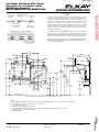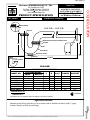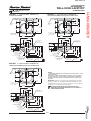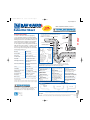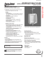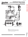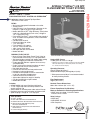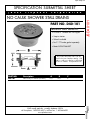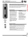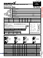
1
Plumbing Submittals Corelabs Phase 2 Submitted By SC Plumbing Co. 2/28/2012 Moore Supply Co League City 2430 West Main, (Hwy 518) League City, TX 77573 Phone: 281-332-6225 Fax: 281-338-0060 www.mooresupply.com Spec# Table of Contents 1 2 3 4 5 6 7 8 ............ ** EDF-1 ** /00021258179 EL EMABFTL8SC SS BI/LVL COOLER MG8912CBECO MG 8912CBECO 1-1/2 17GA P-TRAP BR N MG2165 2165 1/2IPSX3/8OD LAV SUPPLY CP E98324C EL 98324C KIT-CANE APRON-SS ............ ** TRAP GUARDS ** TG33ZURN TG33-ZURN TRPGRD F/ZRN Z400/Z41 STR ............ ** L-1 ** 9 /00021258184 A/S 0614.000.020 WH LAV 10 CF404A317CP CF 404-317CP LAV FCT CP 11 MG155AECO MG 155AECO 1-1/4IN OUTLET GRID DRN 12 MG8872CBECO MG 8872CBECO 1-1/4 17GA P-TRAP NUT 13 CF1006CP CF 1006-CP 1/2X1/2 ANG LAV SP EA CP 14 T102W 102-EZ P-TRAP/2 STOPS INSUL KIT WH 15 ............ ** L-2 ** 16 17 AS0356015WH AS 0356.015 LUCERNE 20X18 LAV 8C WH /00021258185 CF 786GN2FC HOSPITAL FTG CP 18 MG155WCECO MG 155WCECO OFFSET GRID DRAIN 19 MG8872CBECO MG 8872CBECO 1-1/4 17GA P-TRAP NUT 20 MG2165LK 2165LK 1/2IPSX3/8OD LAV SPPLY LK CP 21 T102W 102-EZ P-TRAP/2 STOPS INSUL KIT WH 22 T105W 105-EZ TRUEBRO HANDI LAV OFST KT WH 23 ............ ** U-1 ** 24 /00021258186 A/S 6590.001.020 .125 GPF URINAL Spec# 25 Table of Contents ............ ** WC-1,WC-2 ** 26 /00021298404 AS 2856.128 AFWLL EL 1.28 W/FV COMB 27 B1655CWHI 1655C BEMIS XH EL OF CLO SEAT WHT 28 29 30 ............ ** LS-1 ** /00021258189 CF 930-VR317CP DECK WATER FITT CP ............ ** SH-1 ** 31 L1363BFSCLWH 1363-BFSC 36IN F/G ADA SHR LH ST WH 32 JSD40101 JS D40-101 (101-PNC) SHWR DRN W/STR 33 /00021258190 A/S 1662.604.002 CP SHR KT 24 BAR 34 /00021258192 A/S T372.248.002 CP SHWR TRIM ONLY 35 ............ QUALIFY 4 WEEK ETA 36 /00021258193 A/S 1662.600.002 SHW KIT 24 BAR 37 /00021258194 A/S 1660.400.002 CP IN-LINE VB 38 39 40 41 42 43 44 45 ............ ** EWH-1 ** /00021298405 RHEEM ELDS-52 208VT/3PH/4KW 8KW SIM W34N36 N-36(36A) WATTS 3/4 VAC RELIEF VALV ............ ADD BELOW IF NEEDED PLT5 WT PLT-5(DET5) 2 GAL EXPANSION TANK ............ ** DHWP-1 ** /00021298406 GRUNDFOS UP-26-96BF 1/12HP BRNZ PMP ............ QUALIFY ALT TO B&G Spec Seq#: 1 ** EDF-1 ** Spec Seq#: 2 ® SPECIFICATIONS GENERAL Self-contained, double wall hung electric refrigerated, water cooler. Capacity 8.0 GPH of 50°F drinking water, based upon 80°F inlet water and 90°F ambient. All models have a hooded stream projector with self closing push bars on front and both right and left sides. Patented* valve with built-in flow regulator provide constant stream from 20 to 105 psi (138 to 724 KPa) water pressure. Bubbler orifice fully protected to meet all sanitary codes. NOTE: Minimum 40 psi supply line pressure required in special circumstances where both sides of bi-level are in use simultaneously to ensure adequate stream height. Does not apply to non-refrigerated units. Pressurized stainless steel evaporator/storage tank for long life. Waterways are certified NSF/ANSI 61, far exceeding the requirements of the Safe Drinking Water Act. Stainless steel water tank is located after bubbler valve, so that the tank is subject to line pressure only when push bar is pressed. ADA COMPLIANT These Water Coolers comply with the requirements of A.D.A. (Americans with Disabilities Act) when properly installed. Also meets the guidelines for children’s environments providing the floor to orifice height is 30" or less and proper clear floor space is provided for parallel approach. (Based on Architectural and Transportation Barriers Compliance Board final ruling.) Check Local and State Codes. NO LEAD DESIGN These Water Coolers are certified to be lead-free as defined by the Safe Drinking Water Act. Elkay Water Coolers are manufactured with a waterway system utilizing copper components and completely lead-free materials. These waterways have no lead because all lead materials, such as leaded brass, have been removed. All joints are brazed using silver solder only. No lead solder is permitted. A strainer with an easily cleanable screen is provided to allow trapping and convenient removal of waterborne particulate of 140 microns and larger prior to their entry into the water cooler. These water coolers are certified to NSF/ANSI 61. CAPACITIES CHART Model Number EMABFTL8C **GPH of 50°F Drinking Water Room Temperature °F Volt./ Base 70°F 80°F 90°F Hertz Rate (21°C) (27°C) (32°C) 120V/ 8.0 60Hz EMABFTLDDC – – Rated Watts Full Glass Load Filler Amps Option Filter Option Ship. Wt. Lbs. (Kg.) 9.7 8.8 8.0 370 4.0 No Yes 92 – – – – – No Yes 70 **Based on 80°F (27°C) inlet water temperature. Rated watts shown are based on operational (run) time, in compliance with A.R.I. Standard 1010 conditions. Specific applications will determine the actual watts consumed per hour. Watts consumed will be based on number of people served per hour (usage), ambient temperatures, and inlet water temperature. COOLING SYSTEM Motor Compressor: Hermetically sealed, reciprocating type, 120 Volt/60 Hz, single phase. Sealed-in lifetime oil supply. Equipped with electric cord and three prong molded rubber plug. Condenser: Fan cooled, copper tube with aluminum fins. Fan motor is permanently lubricated. Model EMABFTL8C Cooling Unit: Combination tube-tank type. Tube portion is continuous coil of copper tubing. Fully insulated with EPS foam which meets Underwriters Laboratories Inc. requirements for self extinguishing material. Refrigerant Control: Refrigerant HFC-134a is controlled by accurately calibrated capillary tube for positively trouble-free operation. Temperature Control: Enclosed adjustable thermostat is factory preset. Requires no adjustment other than for altitude requirements. Easily accessible. CONSTRUCTION Frame: Galvanized structural steel chassis supports fountain top and cabinet panels. Fountain Top: Series 300 one piece stainless steel top, polished to a uniform Elkay bright luster finish. Basin has embossed bubbler pad. Exclusive Flexi-Guard® Safety Bubbler*: Innovative design utilizes a pliable polyester elastomer to prevent accidental mouth injuries. Flex on impact, then returns to original position. Strong. Abrasion-resistant. Anti-sweat. Bubbler meets UL requirements and all sanitary codes and is keyed in location to prevent rotation. Cabinet: Cabinet design allows for flush to wall mounting. No recess space is required. Includes bottom cover plate fastened with standard screws. Color Selection: Light Gray Granite furnished as standard. Stainless steel available at extra cost. ALSO AVAILABLE Model LMABFTL8C: Same as EMABFTL8C with EWF172 water filter factory installed. 5 YEAR LIMITED WARRANTY on the refrigeration system of the unit. Electrical components and water system are warranted for 12 months from date of installation. Sample Certificate available on request. Elkay Pressure-Type Water Coolers are designed to operate on 20 psi (138 KPa) to 105 psi (724 KPa) supply line pressure. If inlet pressure is above 105 psi (724 KPa), a pressure regulator must be installed in the supply line. Any damage caused by reason of connecting this product to supply line pressures lower than 20 psi (138 KPa) or higher than 105 psi (724 KPa) is not covered by the warranty. STANDARDS Elkay Electric Air Cooled Water Coolers are listed by Underwriters Laboratories Inc. and comply with both Canadian and U.S. Requirements. * Patent #4,481,971 In keeping with our policy of continuing product improvement, Elkay reserves the right to change product specifications without notice. Elkay elkayusa.com This specification describes an Elkay product with design, quality and functional benefits to the user. When making a comparison of other producers’ offerings, be certain these features are not overlooked. 2222 Camden Court Oak Brook, IL 60523 Printed in U.S.A. ©2007 Elkay (Rev. 7/07) 12-53B /00021258179 Two Station Wall Mount Water Cooler Barrier-Free Access (Adult or Child) NSF/ANSI 61 Compliant Models EMABFTL8C and EMABFTLDDC Spec Seq#: 2 Two Station Wall Mount Water Cooler Barrier-Free Access (Adult or Child) NSF/ANSI 61 Compliant Models EMABFTL8C and EMABFTLDDC ® INSTALLER PLEASE NOTE: IMPORTANT THIS WATER COOLER HAS BEEN DESIGNED AND BUILT TO PROVIDE WATER TO THE USER WHICH HAS NOT BEEN ALTERED BY MATERIALS IN THE COOLER WATERWAYS. THE GROUNDING OF ELECTRICAL EQUIPMENT SUCH AS TELEPHONE, COMPUTERS, ETC. TO WATER LINES IS A COMMON PROCEDURE. THIS GROUNDING MAY BE IN THE BUILDING BUT MAY ALSO OCCUR AWAY FROM THE BUILDING. THIS GROUNDING CAN CAUSE ELECTRICAL FEEDBACK INTO A WATER COOLER CREATING AN ELECTROLYSIS WHICH CREATES A METALLIC TASTE OR CAUSES AN INCREASE IN THE METAL CONTENT OF THE WATER. THIS CONDITION IS AVOIDABLE BY INSTALLING THE COOLER USING THE PROPER MATERIALS AS SHOWN BELOW. NOTICE THIS WATER COOLER MUST BE CONNECTED TO THE WATER SUPPLY USING A DIELECTRIC COUPLING. THE COOLER IS FURNISHED WITH A NON-METALLIC STRAINER WHICH MEETS THIS REQUIREMENT. THE DRAIN TRAP WHICH IS PROVIDED BY THE INSTALLER SHOULD ALSO BE PLASTIC TO COMPLETELY ISOLATE THE COOLER FROM THE BUILDING PLUMBING SYSTEM. MINIMUM 40 PSI SUPPLY LINE PRESSURE REQUIRED IN SPECIAL CIRCUMSTANCES WHEN BOTH SIDES OF BILEVEL ARE IN USE SIMULTANEOUSLY TO ENSURE ADEQUATE STREAM HEIGHT. DOES NOT APPLY TO NON-REFRIGERATED UNITS. 18-1/16" (459mm) 5-3/4" (146mm) 5-3/4" (146mm) 1-3/8" 1-3/8" (35mm) (35mm) 5/16" (8mm) DIA. (10 HOLES) 18-5/8" (473mm) 5-3/4" (146mm) 2-5/8" (67mm) 5-3/4" (146mm) HANGER BRACKET 1-3/8" 1-3/8" (35mm) (35mm) 6-1/2" (165mm) 4-9/16" (116mm) E D E 7-1/4" (185mm)) 39-1/2" (1003mm) ORIFICE HEIGHT 11/16" (18mm) A F 37-1/2" (951mm) 2-9/16" (65mm) 5" (127mm) F 2-7/16" (63mm) 10" (254mm) 20-1/8" (511mm) 3-1/2" (89mm) 4-1/2" (114mm) B 20-3/8" (517mm) 25-1/8" (638mm) 5" (127mm) 18-3/4" (476mm) 8" (203mm) 33" (838mm) ORIFICE HEIGHT C 31-7/8" (810mm) RIM HEIGHT 4-3/4" (121mm) * 27" (686mm) 13-7/8" (352mm) 6-3/4" (171mm) 12-5/16" (313mm) FINISHED FLOOR REDUCE HEIGHT BY 3" FOR INSTALLATION OF CHILDRENS ADA COOLER LEGEND: A = RECOMMENDED WATER SUPPLY LOCATION. SHUT OFF VALVE (NOT FURNISHED) TO ACCEPT 3/8" O.D. UNPLATED COPPER TUBE. B = RECOMMENDED LOCATION FOR WASTE OUTLET 1-1/2" O.D. DRAIN C = 1-1/2" TRAP NOT FURNISHED D = ELECTRICAL SUPPLY (3) WIRE RECESSED BOX E = INSURE PROPER VENTILATION BY MAINTAINING 6" (152mm) MIN. CLEARANCE FROM CABINET LOUVERS TO WALL. F = 7/16" BOLT HOLES FOR FASTENING UNIT TO WALL * ADA REQUIREMENT Elkay 12-53B (Rev. 7/07) 2222 Camden Court Oak Brook, IL 60523 elkayusa.com Printed in U.S.A. ©2007 Elkay /00021258179 ROUGH-IN DIMENSIONS Spec Seq#: 3 60 Grandview Court P.O. Box 746 Cheshire, CT 06410 203-699-1801 Fax: 203-699-1813 www.mcguiremfg.com P R O D U C T S 8872CBECO, C8872CECO, 8904CBECO 8912CBECO, C8912CECO, 8912CNCBECO, 8912C18BECO PRODUCT SPECIFICATION Job Name: Cast Body P-Trap With or Without Cleanout Submittal Number: Rubber Washer Filet 1-1/4" O.D. – 1-1/2" O.D. Slip Nut Metal Bead with Tapered Washer Joint Slip Nut A Flange B Filet Cast Body 1-1/2" Neoprene Gasket Available less cleanout Part #8912CNCBECO Cleanout C to E ECO-LINE ROUGHING MEASUREMENTS TRAP DIMENSIONS MODEL NO. A B C to E INLET OUTLET 8872CBECO 11" 4-1/2" 1-1/4" 1-1/4" 5" C8872CECO 10" 4-1/2" 1-1/4" 1-1/4" 5" 8904CBECO 1-1/2", 2" 2" 5" 6" 13" 8912CBECO 12" 4-1/2" 1-1/2" 1-1/2", 1-1/4" 5" C8912CECO 4-1/2" 10-1/2" 1-1/2" 1-1/2" 5" 8912CNCBECO 1-1/2", 1-1/4" 1-1/2" 4-5/8" 4-1/8" 12" 8912C18BECO 1-1/2", 1-1/4" 1-1/2" 5" 4-1/2" 18" FED SPEC W.W.P. 541 CAST BRASS P-TRAP MINIMUM SEAL 2" FLANGE SLIP NUT Box Shallow Box Box Shallow Box Box Brass Zinc Brass Brass Zinc Brass Brass Certified See options and accessories section for details on product variations. Specifications: Chrome plated P-Trap shall be cast brass body, with or without cleanout, with 17 gauge seamless tubular wall bend and flange. © 2011 McGuire Manufacturing Company All rights reserved / I Traps / www.mcguiremfg.com/products MG8912CBECO Part No. McGuire Manufacturing Co., Inc. QUALITY DESIGNED Spec Seq#: 4 P R O D U C T S Part No. McGUIRE MFG. CO., INC. 60 Grandview Court P.O. Box 746 Cheshire, CT 06410 203-699-1801 Fax 203-699-1813 www.mcguiremfg.com Product Job Name: 2165, 2165LK, 2167, 2167LK Lavatory Supply 1/2" I.P.S. x O.D. Specification Submittal Number: Wheel Handle w/ 12" Riser MG2165 QUALITY DESIGNED Loose Key w/ 12" Riser 12" 12" Brass Stem Brass Stem A A C C B B NO. ROUGHING MEASUREMENTS A B C 2165 2165LK 2167 2167LK 1/2" I.P.S. x 3/8" O.D. 1/2" I.P.S. x 3/8" O.D. 1/2" I.P.S. x 1/2" O.D. 1/2" I.P.S. x 1/2" O.D. 1 1 1 1 1-1/2" 2-1/4" 1-1/2" 2-1/4" 3/4" 3/4" 3/4" 3/4" Certified LK designates Loose Key See options and accessories section for details on product variations. Specifications: Supply kit shall include chrome plated brass stops with full turn brass stem, no plastic, (12, 15, 20) inch chrome plated copper risers and (shallow, deep, bell) (steel, brass) or (forged brass with set screw) flange. Inlet shall be (3/8, 1/2) inch (IPS, sweat, compression). Outlet shall be (3/8, 1/2) inch (IPS, compression). Supply kit shall be McGuire . Supply kit shall be certified by CSA or other recognized testing authority and bear manufacturer and testing mark. Stop to be certified to 200 psi line pressure. © Copyright 2002 MCGUIRE MANUFACTURING COMPANY Printed U.S.A. Spec Seq#: 5 ® Accessory Apron Model 98234C SPECIFICATIONS GENERAL Accessory apron designed to bring Elkay VRC series vandalresistant water coolers in compliance with the Americans with Disabilities Act (A.D.A.) when units are mounted on an exposed wall. This apron provides the mandatory 27" (686mm) floor to underside requirement when properly installed.* E98324C CONSTRUCTION 300 Series stainless steel construction. *Adult ADA requirement. 24" (609mm) for child ADA requirement. Adjust all other measurements accordingly. Model 98234C UNIT (W/O REFRIG.) CANE TOUCH APRON 1/8" DIA. HOLE In keeping with our policy of continuing product improvement, Elkay reserves the right to change product specifications without notice. Elkay elkayusa.com This specification describes an Elkay product with design, quality and functional benefits to the user. When making a comparison of other producers’ offerings, be certain these features are not overlooked. 2222 Camden Court Oak Brook, IL 60523 Printed in U.S.A. ©2006 Elkay (6/06) 16-28 Spec Seq#: 6 ** TRAP GUARDS ** TG33ZURN Spec Seq#: 7 Spec Seq#: 8 ** L-1 ** Spec Seq#: 9 STUDIO™ UNDERCOUNTER SINK VITREOUS CHINA BARRIER FREE /00021258184 STUDIO™ UNDERCOUNTER SINK • Rectangular undercounter mount sink • Made from vitreous china • Front overflow • Supplied with mounting kit (047194-0070A) and template ❏ 0614.000 Unglazed Rim 540 x 387mm (21-1/4" x 15-1/4") ❏ 0614.300 Glazed underside Bowl size: 464mm (18-1/4") wide 308mm (12-1/8") front to back 171mm (6-3/4") deep ❏ 0618.000 Unglazed Rim 600 x 422mm (23-5/8" x 16-5/8") ❏ 0618.300 Glazed underside Bowl size: 537mm (21-1/8") wide 356mm (14") front to back 152mm (6") deep Compliance Certifications Meets or Exceeds the Following Specifications: • ASME A112.19.2M for Vitreous China Fixtures • CAN/CSA B45 series FINISHED WALL OR SPLASHBACK A A B 1-1/16 (27mm) 4 (102mm) SPREAD 1-1/4 (32mm) 8 (203mm) B 51mm (2) MIN. DETAIL OF MOUNTING CLIP (KIT No.47194.0070A) 83mm (3-1/4) C LAVA EDGE OF COUNTER TOP CUTOUT F BRASS INSERT H 19mm (3/4) MIN. CLIP MACH. SCREW REFER TO INSTRUCTIONS PROVIDED WITH KIT FOR ADDITIONAL INFORMATION G 41mm (1-5/8) E SEALING COMPOUND *330mm (13) *273mm (10-3/4) COUNTERTOP (BY OTHERS) 13mm (1/2) (11) 22mm (7/8) 203mm (8) MIN. 203mm (8) 1-1/4 O.D. WASTE 1-1/4 O.D. TAILPIECE CAT. NO. 0614.000 0618.000 610mm (24) 102mm (4) *279mm D 864mm (34) To Be Specified: ❏ Color: ❏ White ❏ Bone ❏ Linen ❏ Black ❏ Faucet*: ❏ Faucet Finish: ❏ Supplies: ❏ 1-1/4" Trap: FITTING CENTER-SET E 540mm (21-1/4) 600mm (23-5/8) F 387mm (15-1/4) 422mm (16-5/8) G 464mm (18-1/4) 537mm (21-1/8) SUPPLIES AS REQ'D. 38mm (1-1/2) H 308mm (12-1/8) 356mm (14) ADA DRAIN OUTLET C 114mm (4-1/2) 108mm (4-1/4) 864mm (34) DRAWING FOR DIMENSIONAL PURPOSES ONLY. IT IS NOT AN EXACT REPRESENTATION. 686mm (27) MIN. D 209mm (8-1/4) 209mm (8-1/4) 152mm (6) MAX. BARRIER FREE CLEARANCE 229mm (9) MIN. FINISHED FLOOR NOTES: WE RECOMMEND USING BASIN AS A TEMPLATE TO DETERMINE PROPER CONTOUR. CUT COUNTERTOP 38MM (1-1/2") INSIDE BASIN CONTOUR. DIMENSIONS SHOWN FOR LOCATION OF SUPPLIED AND “P" TRAP ARE *SUGGESTED. ▼ UNDERCOUNTER MOUNTING KIT SUPPLIED WITH SINK. MEETS THE AMERICANS WITH DISABILITIES ACT GUIDELINES FITTINGS NOT INCLUDED WITH FIXTURE AND MUST BE ORDERED AND ANSI A117.1 ACCESSIBLE AND USABLE SEPARATELY. SEALING COMPOUND SUPPLIED BY OTHERS. BUILDINGS AND FACILITIES - CHECK LOCAL CODES. ● Countertop 864mm (34") from finished floor. Lavatory IMPORTANT: Dimensions of fixtures are nominal and may vary within the range installed 102mm (4") from front edge of countertop. of tolerances established by ANSI Standard A112.19.2. Countertop thickness to be 25mm (1") maximum. These measurements are subject to change or cancellation. No responsibility is assumed for use of superseded or voided pages. * See faucet section for additional models available © 2008 AS America Inc. J48 Revised 2/08 MECHANICAL FAUCETS 404-317CP Sink Faucets Product Type ___________________________________________________ Deck Mounted Concealed Hot and Cold Water Sink Faucet Job Name ________________________________________________ Features & Specifications ___________________________________________________ • 8" Fixed Centers • 2.2 GPM (8.3 L/min) Aerator • 4" Wristblade Handle • Quaturn Compression Operating Cartridge • 1/2" NPSM Supply Inlets and Coupling Nut for 3/8" or 1/2" Flexible Riser • 5" Center to Center Rigid Cast Brass Spout • CFNow! Item Ships in 5 Days Item Number _____________________________________________ Section/Tag ______________________________________________ Model Specified ___________________________________________ Architect _________________________________________________ Engineer _________________________________________________ Contractor ________________________________________________ [ ] Submitted as Shown Performance Specification ___________________________________________________ • Rating Operating Pressure: 20-125 PSI • Rated Operating Temperature: 40-140ºF [ ] Submitted with Variations Date _____________________________________________________ Warranty ___________________________________________________ • Lifetime Limited Faucet Warranty • 5-Year Limited Cartridge Warranty • 1-Year Limited Finish Warranty Codes & Standards ___________________________________________________ • ASME A112.18.1/CSA B125.1 • Certified to NSF/ANSI 61, Section 9 by CSA • ADA ANSI/ICC A117.1 2100 South Clearwater Drive Des Plaines, IL P: 847/803-5000 F: 847/803-5454 Technical: 800/TEC-TRUE www.chicagofaucets.com Last Revision: 07/25/2011 • Date Printed: 09/8/2011 • Product specifications subject to change without notice 404-317CP Sink Faucets Architect/Engineer Specification ________________________________________________________________________________________________________ Chicago Faucets No. 404-317CP, Deck Mounted Concealed Hot and Cold Water Sink Faucet, polished chrome plated solid brass construction. 5" Center to Center Rigid Cast Brass Spout. 2.2 GPM (8.3 L/min) Pressure Compensating Softflo Aerator. 4" Metal Wristblade handle(s) with Sixteen Point Tapered Broach and Secured Blue and Red Buttons. Quaturn™ rebuildable compression cartridge, opens and closes 90°, closes with water pressure, features square tapered stem. Integral inlet shank(s) contains standard 1/2" NPSM Supply Inlets and Coupling Nut for 3/8" or 1/2" Flexible Riser. Mounting hardware included. This product meets ADA ANSI/ICC A117.1 requirements and is tested and certified to industry standards: ASME A112.18.1/CSA B125.1, and Certified to NSF/ANSI 61, Section 9 by CSA. Operation and Maintenance ________________________________________________________________________________________________________ Installation should be in accordance with local plumbing codes. Flush all pipes thoroughly before installation. After installation, remove spout outlet or flow control and flush faucet thoroughly to clear any debris. Care should be taken when cleaning the product. Do not use abrasive cleaners, chemicals or solvents as they can result in surface damage. Use mild soap and warm water for cleaning and protecting the life of Chicago Faucet products. For specific operation and maintenance refer to the installation instructions and repair parts documents that are located at www.chicagofaucets.com. Chicago Faucets, member of the Geberit Group, is the leading brand of commercial faucets and fittings in the United States, offering a complete range of products for schools, laboratories, hospitals, office buildings, food service, airports and sport facilities. Call 1.800.TECTRUE or 1.847.803.5000 Option 1 for installation or other technical assistance. 2100 South Clearwater Drive Des Plaines, IL P: 847/803-5000 F: 847/803-5454 Technical: 800/TEC-TRUE www.chicagofaucets.com Last Revision: 07/25/2011 • Date Printed: 09/8/2011 • Product specifications subject to change without notice Spec Seq#: 11 Part No. McGuire Manufacturing Co., Inc. 60 Grandview Court P.O. Box 746 Cheshire, CT 06410 203-699-1801 Fax: 203-699-1813 www.mcguiremfg.com P R O D U C T S PRODUCT SPECIFICATION Job Name: 155AECO Open Grid P.O. Plug Submittal Number: 2-1/4" Polished Chrome Cast Brass P.O. Plug 2-9/16" 19 Holes 7/32" 1"Min. Thread 1-1/2" - 16 Rubber Washer Friction Washer Brass Locknut Threaded Joint 8-5/16" 6" ECO-LINE 1-1/4" O.D. Certified Specifications: Cast Brass Chrome Plated Open Grid P.O. Plug with 17 gauge 1-1/4" x 6" seamless brass tailpiece, brass locknut, heavy rubber basin washer and fiber friction washer. Drain shall be in compliance with CSA or other recognized testing authority and bear both manufacturer and testing mark. © 2009 McGuire Manufacturing Company All rights reserved / III Strainers and P.O. Plugs / www.mcguiremfg.com / products MG155AECO QUALITY DESIGNED Spec Seq#: 12 60 Grandview Court P.O. Box 746 Cheshire, CT 06410 203-699-1801 Fax: 203-699-1813 www.mcguiremfg.com P R O D U C T S 8872CBECO, C8872CECO, 8904CBECO 8912CBECO, C8912CECO, 8912CNCBECO, 8912C18BECO PRODUCT SPECIFICATION Job Name: Cast Body P-Trap With or Without Cleanout Submittal Number: Rubber Washer Filet 1-1/4" O.D. – 1-1/2" O.D. Slip Nut Metal Bead with Tapered Washer Joint Slip Nut A Flange B Filet Cast Body 1-1/2" Neoprene Gasket Available less cleanout Part #8912CNCBECO Cleanout C to E ECO-LINE ROUGHING MEASUREMENTS TRAP DIMENSIONS MODEL NO. A B C to E INLET OUTLET 8872CBECO 11" 4-1/2" 1-1/4" 1-1/4" 5" C8872CECO 10" 4-1/2" 1-1/4" 1-1/4" 5" 8904CBECO 1-1/2", 2" 2" 5" 6" 13" 8912CBECO 12" 4-1/2" 1-1/2" 1-1/2", 1-1/4" 5" C8912CECO 4-1/2" 10-1/2" 1-1/2" 1-1/2" 5" 8912CNCBECO 1-1/2", 1-1/4" 1-1/2" 4-5/8" 4-1/8" 12" 8912C18BECO 1-1/2", 1-1/4" 1-1/2" 5" 4-1/2" 18" FED SPEC W.W.P. 541 CAST BRASS P-TRAP MINIMUM SEAL 2" FLANGE SLIP NUT Box Shallow Box Box Shallow Box Box Brass Zinc Brass Brass Zinc Brass Brass Certified See options and accessories section for details on product variations. Specifications: Chrome plated P-Trap shall be cast brass body, with or without cleanout, with 17 gauge seamless tubular wall bend and flange. © 2011 McGuire Manufacturing Company All rights reserved / I Traps / www.mcguiremfg.com/products MG8872CBECO Part No. McGuire Manufacturing Co., Inc. QUALITY DESIGNED MECHANICAL FAUCETS 1006-CP Stops and Supplies Product Type ___________________________________________________ Angle with Supply Tube Mounted Angle Stop Fitting with Supply Tube and Loose Key Job Name ________________________________________________ Item Number _____________________________________________ Features & Specifications ___________________________________________________ • Stops with 1/2" Inlet • 2 1/4 Tee Handle • Slow Compression Operating Cartridge • 1/2" NPT Female Thread Inlet • 1/2" O.D. Female Compression Outlet • Slip Wall Flange • 1/2" O.D. x 12" Bullnose Flexible Supply Riser • CFNow! Item Ships in 5 Days Performance Specification ___________________________________________________ • Rating Operating Pressure: 20-125 PSI • Rated Operating Temperature: 40-140ºF Section/Tag ______________________________________________ Model Specified ___________________________________________ Architect _________________________________________________ Engineer _________________________________________________ Contractor ________________________________________________ [ ] Submitted as Shown [ ] Submitted with Variations Date _____________________________________________________ Warranty ___________________________________________________ • Lifetime Limited Faucet Warranty • 5-Year Limited Cartridge Warranty • 1-Year Limited Finish Warranty Codes & Standards ___________________________________________________ • ASME A112.18.1/CSA B125.1 • Certified to NSF/ANSI 61, Section 9 by CSA 2100 South Clearwater Drive Des Plaines, IL P: 847/803-5000 F: 847/803-5454 Technical: 800/TEC-TRUE www.chicagofaucets.com Last Revision: 08/12/2011 • Date Printed: 09/8/2011 • Product specifications subject to change without notice 1006-CP Stops and Supplies Architect/Engineer Specification ________________________________________________________________________________________________________ Chicago Faucets No. 1006-CP, Angle with Supply Tube Mounted Angle Stop Fitting with Supply Tube and Loose Key, polished chrome plated solid brass construction. 2 1/4 Metal Tee handle(s) with Tapered Square. Slow compression rebuildable cartridge, opens and closes 360° for fine adjustment, closes with water pressure, features square tapered stem. Integral inlet shank(s) contains standard 1/2" NPT Female Thread Inlet. 1/2" O.D. Female Compression Outlet. Slip Wall Flange. 1/2" O.D. x 12" Bullnose Flexible Supply Riser. Mounting hardware included. This product is tested and certified to industry standards: ASME A112.18.1/CSA B125.1, and Certified to NSF/ANSI 61, Section 9 by CSA. Operation and Maintenance ________________________________________________________________________________________________________ Installation should be in accordance with local plumbing codes. Flush all pipes thoroughly before installation. After installation, remove spout outlet or flow control and flush faucet thoroughly to clear any debris. Care should be taken when cleaning the product. Do not use abrasive cleaners, chemicals or solvents as they can result in surface damage. Use mild soap and warm water for cleaning and protecting the life of Chicago Faucet products. For specific operation and maintenance refer to the installation instructions and repair parts documents that are located at www.chicagofaucets.com. Chicago Faucets, member of the Geberit Group, is the leading brand of commercial faucets and fittings in the United States, offering a complete range of products for schools, laboratories, hospitals, office buildings, food service, airports and sport facilities. Call 1.800.TECTRUE or 1.847.803.5000 Option 1 for installation or other technical assistance. 2100 South Clearwater Drive Des Plaines, IL P: 847/803-5000 F: 847/803-5454 Technical: 800/TEC-TRUE www.chicagofaucets.com Last Revision: 08/12/2011 • Date Printed: 09/8/2011 • Product specifications subject to change without notice Lav Guard2 Sbmttl 2-07 2/7/07 2:22 PM Page 1 Spec Seq#: 14 ADA-compliant undersink protection Submittal Sheet LAV GUARD® 2 E-Z Series waste and supply piping covers satisfy ADA compliance requirements. Built-in E-Z Grip internal fasteners and internal, E-Z Tear-To-Fit trimming feature allow for fast installation without tools. Series #100 E-Z kits are designed to fit on all tubular and cast brass P-trap assemblies. Series #400 kits are the “original” LAV GUARD design and fit schedule 40 ABS and PVC P-trap assemblies — regardless of their geometry or rotational offset. Valve cover completely encloses angle valve and supply tube for both handled and keyed type water stops. ____________________________________________ Material Molded vinyl ____________________________________________ Nominal Wall 1/8" constant ____________________________________________ Durometer 70 -80 - Shore A ____________________________________________ UV Protection Will not fade or discolor ____________________________________________ Durability Virtually indestructible ____________________________________________ Internal, E-Z Tear-To-Fit trim feature ____________________________________________ Trimming (E-Z Series) Internal E-Z Grip fasteners (reusable) ____________________________________________ Fasteners (E-Z Series) Shown with Accessory #105 E-Z (fits all standard 5" offset wheelchair strainers). Accessories105 E-Z,106 E-Z, and 107 E-Z can be purchased separately. 9" supply tube cover with internal E-Z Tear-To-Fit trim grooves NOTE: Accessory #105 E-Z is included in #103 E-Z kits. Vent slots keep valve dry 10" tailpiece cover E-Z Tear-To-Fit trim grooves Internal ribs add cushioning and thermal resistance E-Z Grip internal fasteners Tear-to-fit on internal dimensioned tear lines. Install over pipes. Press finger recesses to engage internal fasteners. To remove covers, firmly pull seam apart using a strong grip. T102W General Description: 10" waste arm cover with internal E-Z Tear-To-Fit trim feature J-bend covers all tubular and cast brass configurations E-Z Series Shown Vent hole keeps P-trap dry #100 E-Z Series (shown above right) for tubular and cast brass P-trap assemblies. #400W * Series (original design) for schedule 40 P-trap assemblies. Color China white ____________________________________________ Paintability Apply Latex paint ____________________________________________ ■ Model #99 E-Z ■ Model #102 E-Z ■ Accessory #105-K One angle valve and supply cover __________________ ____________________ Burning Characteristics Self extinguished ASTM D-635 0 sec (ATB) 0 mm (AEB) ____________________________________________ One P-trap cover, two angle valves and covers ___________________ One P-trap cover _________________ Bacteria/Fungus ASTM G21 and G22/ Resistance Result: 0 growth ____________________________________________ Maintenance Use common detergents ____________________________________________ ■ Model #100 E-Z ■ Model #400W* One P-trap cover _________________ ■ Model #101 E-Z One P-trap cover, one angle valve cover _________________ ■ Model #401W* Manufactured under one or more of the following U.S. or Canadian patents. Other patents pending. 5,303,730 5,360,031 5,524,669 5,564,463 5,678,598 5,699,828 5,915,412 5,915,413 5,901,739 5,960,820 2,075,324 2,119,427 2,136,027 2,158,083 One P-trap cover, one angle valve cover One P-trap cover, two angle valves and covers ___________________ ■ Model #103 E-Z One P-trap cover, two angle valves and supply covers, one 5" offset tailpiece wheelchair strainer cover ___________________ One basket strainer cover and offset waste cover (adjustable to 18") ____________________ ■ Accessory #107 E-Z Two basket strainer covers and center or end outlet waste cover (adjustable) ____________________ ■ Accessory #Ex99 E-Z One 16" extension for water supply One 5" offset tailpiece wheelchair strainer assembly ■ Accessory #Ex100 E-Z *All #400W series items are the “original” LAV GUARD design and construction. Specifications may change without notice. Accessory 106 E-Z ■ Accessory #106 E-Z ■ Accessory #105 E-Z ® Accessory 105 E-Z IPS Corporation, 202 Industrial Park Lane, Collierville, TN 38017 (901) 853-5001 (800) 340-5969 FAX: (901) 853-5008 e-mail: [email protected] Internet: http://www.truebro.com ■ Model #402W* Kohler 6" offset ____________________ One 16" extension for drain waste arm or tailpiece Accessory 107 E-Z (Configuration Options Shown) Center Outlet End Outlet ________________________________________ Designer _________________________________________ Job/Location TRUEBRO reserves the right to make product and material changes at any time without notice. 2 / 07 Spec Seq#: 15 ** L-2 ** Spec Seq#: 16 LUCERNE™ WALL-HUNG LAVATORY VITREOUS CHINA AS0356015WH BARRIER FREE LUCERNE™ WALL-HUNG LAVATORY • Wall-hung sink • Vitreous china • Front overflow • D-shaped bowl • Self-draining deck area with contoured back and side splash shields • Faucet ledge Faucet holes on 203mm (8") centers (Illus.): ❏ 0356.028 For exposed bracket support Shown with 4801.862 Amarilis Heritage faucet with Triune Cross handles (not included) ❏ 0356.015 For wall hanger (included) or concealed arms support ❏ 0356.037 For wall hanger (included) or concealed arms support • Extra right-hand hole ❏ 0356.073 For wall hanger (included) or concealed arms support • Extra left-hand hole 0356.028 Faucet holes on 102mm (4") centers: ❏ 0355.027 For exposed bracket support ❏ 0355.012 For wall hanger (included) or concealed arms support ❏ 0355.034 For wall hanger (included) or concealed arms support • Extra right-hand hole ❏ 0355.056 For wall hanger (included) or concealed arms support • Extra left-hand hole Single center faucet hole (Illus.): ❏ 0356.041 For exposed bracket support Shown with 1340.000 metering faucet (not included) ❏ 0356.421 For wall hanger (included) or concealed arms support ❏ 0356.137 For wall hanger (included) or concealed arms support • Extra right-hand hole ❏ 0356.115 For wall hanger (included) or concealed arms support • Extra left-hand hole Nominal Dimensions: 521 x 464mm (20-1/2" x 18-1/4") Bowl sizes: 381mm (15") wide 254mm (10") front to back 165mm (6-1/2") deep 0356.041 SEE REVERSE FOR ROUGHING-IN DIMENSIONS To Be Specified: ❏ Color: ❏ White ❏ Bone ❏ Silver ❏ Black ❏ Linen ❏ Faucet*: ❏ Faucet Finish: ❏ Supplies: ❏ 1-1/4" Trap: ❏ Nipple: ❏ Bracket Support (by others): ❏ Concealed Arms Support (by others): * See faucet section for additional models available Compliance Certifications Meets or Exceeds the Following Specifications: • ASME A112.19.2 for Vitreous China Fixtures © 2008 AS America Inc. MEETS THE AMERICANS WITH DISABILITIES ACT GUIDELINES AND ANSI A117.1 ACCESSIBLE AND USABLE BUILDINGS AND FACILITIES - CHECK LOCAL CODES. Top of front rim mounted 864mm (34") from finished floor. M19 Revised 2/08 Spec Seq#: 16 LUCERNE™ WALL-HUNG LAVATORY VITREOUS CHINA 0356.015 8" CTRS FOR WALL HANGER OR CONCEALED ARMS 0356.037 8" CTRS FOR WALL HANGER OR CONCEALED ARMS EXTRA RIGHT HAND HOLE 86 mm (3-3/8) 102 mm (4) 54mm 203 mm (2-1/8) (8) 203 mm (8) FINISHED WALL FINISHED WALL 152 mm (6) 152 mm (6) 86 mm (3-3/8) 102 mm (4) 152 mm (6) 165 mm (6-1/2) 464 mm (18-1/4) 203 mm (8) 152 mm (6) 464 mm (18-1/4) 203 mm (8) 8 mm (5/16) 8 mm (5/16) (6) 25mm (1") DIA. ACCESS HOLES FOR CONC. ARMS (6) 25mm (1") DIA. ACCESS HOLES FOR CONC. ARMS 13 mm (1/2) 521 mm (20-1/2) 425 mm (16-3/4) 425 mm (16-3/4) 267 mm (10-1/2) 206 mm (8-1/8) 10mm (3/8) DIA. ANCHOR SCREW HOLES S-9 HANGER * 352 mm (13-7/8) 27mm X 14mm (1-1/16 x 5/16) SLOTS SUPPLIES AS REQUIRED 1-1/4 O.D. WASTE OUTLET FOR POP-UP DRAIN 1-1/4 O.D. WASTE OUTLET FOR DRAIN PLUG 206 mm (8-1/8) 38 mm (1-1/2) 203 mm (8) FINISHED FLOOR 25 mm (1) 79 mm (3-1/8) mm *298 (11-3/8) mm *286 (11-1/4) 54mm (2-1/8) DIA. HOLES FOR CONCEALED ARMS 114 mm (4-1/2) 102 mm 44 mm (1-3/4) (4) 25 mm (1) 79 mm (3-1/8) 38 mm (1-1/2) 267 mm (10-1/2) 54mm (2-1/8) DIA. HOLES FOR CONCEALED ARMS 114 mm (4-1/2) 102 mm 44 mm (1-3/4) (4) 13 mm (1/2) 521 mm (20-1/2) 10mm (3/8) DIA. ANCHOR SCREW HOLES S-9 HANGER mm *298 (11-3/8) mm *286 (11-1/4) 203 mm (8) mm *352 (13-7/8) 27mm X 14mm (1-1/16 x 5/16) SLOTS SUPPLIES AS REQUIRED 787mm (31) 864mm (34) 1-1/4 O.D. WASTE OUTLET FOR DRAIN PLUG 1-1/4 O.D. WASTE OUTLET FOR POP-UP DRAIN FINISHED FLOOR 787mm (31) 864mm (34) 0356.073 8" CTRS FOR WALL HANGER OR CONCEALED ARMS EXTRA LEFT HAND HOLE 86 mm (3-3/8) 102 mm (4) 54mm (2-1/8) 203 mm (8) FINISHED 152 mm WALL (6) 165 mm (6-1/2) 152 mm (6) 464 mm (18-1/4) 203 mm (8) 8 mm (5/16) (6) 25mm (1") DIA. ACCESS HOLES FOR CONC. ARMS IMPORTANT: Dimensions of fixtures are nominal and may vary within the range of tolerances established by ANSI Standard A112.19.2. These measurements are subject to change or cancellation. No responsibility is assumed for use of superseded or voided pages. 13 mm (1/2) 521 mm (20-1/2) 425 mm (16-3/4) 267 mm (10-1/2) 25 mm (1) 79 mm (3-1/8) 206 mm (8-1/8) 38 mm (1-1/2) LAVATORY DESIGNED TO MEET ADA HANDICAPPED GUIDELINES WITH MOUNTING HEIGHT SET AT 864MM (34") ABOVE FINISHED FLOOR. 54mm (2-1/8) DIA. HOLES FOR CONCEALED ARMS 114 mm (4-1/2) 102 mm 44 mm (1-3/4) (4) NOTES: DIMENSIONS SHOWN FOR LOCATION OF SUPPLIES AND “P” TRAP *ARE SUGGESTED. PROVIDE SUITABLE REINFORCEMENT FOR ALL WALL SUPPORTS. FITTINGS NOT INCLUDED AND MUST BE ORDERED SEPARATELY. CONCEALED ARM SUPPORT AS REQUIRED TO BE FURNISHED BY OTHERS. 10mm (3/8) DIA. ANCHOR SCREW HOLES S-9 HANGER mm *298 (11-3/8) mm *286 (11-1/4) 203 mm (8) mm *352 (13-7/8) 27mm X 14mm (1-1/16 x 5/16) SLOTS SUPPLIES AS REQUIRED 1-1/4 O.D. WASTE OUTLET FOR DRAIN PLUG © 2008 AS America Inc. 1-1/4 O.D. WASTE OUTLET FOR POP-UP DRAIN FINISHED FLOOR 787mm (31) 864mm (34) M20 Revised 8/05 AS0356015WH BARRIER FREE Spec Seq#: 16 LUCERNE™ WALL-HUNG LAVATORY VITREOUS CHINA 0355.012 4" CTRS FOR WALL HANGER OR CONCEALED ARMS 0355.034 4" CTRS FOR WALL HANGER OR CONCEALED ARMS EXTRA RIGHT HAND HOLE 86 mm (3-3/8) 102 mm (4) 54 mm (2-1/8) 203 mm (8) 203 mm (8) FINISHED WALL FINISHED WALL 152 mm (6) 152 mm (6) 464 mm (18-1/4) 102 mm (4) 152 mm (6) 86 mm (3-3/8) 102 mm (4) 464 mm (18-1/4) 102 mm (4) 152 mm (6) 165 mm (6-1/2) 8 mm (5/16) 8 mm (5/16) (6) 25mm (1") DIA. ACCESS HOLES FOR CONC. ARMS (6) 25mm (1") DIA. ACCESS HOLES FOR CONC. ARMS 13 mm (1/2) 521 mm (20-1/2) 13 mm (1/2) 521 mm (20-1/2) 425 mm (16-3/4) 425 mm (16-3/4) 267 mm (10-1/2) 54mm (2-1/8) DIA. HOLES FOR CONCEALED ARMS 114 mm (4-1/2) 102 mm 44 mm (1-3/4) (4) 10mm (3/8) DIA. ANCHOR SCREW HOLES mm *260 (10-1/4) 203 mm (8) S-9 HANGER 206 mm (8-1/8) 38 mm (1-1/2) * 352 mm (13-7/8) 10mm (3/8) DIA. ANCHOR SCREW HOLES S-9 HANGER mm *298 (11-3/8) mm *260 (10-1/4) 203 mm (8) mm *352 (13-7/8) 27mm X 14mm (1-1/16 x 5/16) SLOTS 27mm X 14mm (1-1/16 x 5/16) SLOTS SUPPLIES AS REQUIRED 1-1/4 O.D. WASTE OUTLET FOR POP-UP DRAIN 1-1/4 O.D. WASTE OUTLET FOR DRAIN PLUG 25 mm (1) 79 mm (3-1/8) mm *298 (11-3/8) 206 mm (8-1/8) 54mm (2-1/8) DIA. HOLES FOR CONCEALED ARMS 114 mm (4-1/2) 102 mm 44 mm (1-3/4) (4) 25 mm (1) 79 mm (3-1/8) 38 mm (1-1/2) 267 mm (10-1/2) SUPPLIES AS REQUIRED 787mm (31) 864mm (34) FINISHED FLOOR 1-1/4 O.D. WASTE OUTLET FOR DRAIN PLUG 1-1/4 O.D. WASTE OUTLET FOR POP-UP DRAIN FINISHED FLOOR 787mm (31) 864mm (34) 0355.056 4" CTRS FOR WALL HANGER OR CONCEALED ARMS EXTRA LEFT HAND HOLE 86 mm (3-3/8) 102 mm (4) 54 mm (2-1/8) 203 mm (8) FINISHED 152 mm WALL (6) 165 mm (6-1/2) 152 mm (6) 464 mm (18-1/4) 102 mm (4) 8 mm (5/16) (6) 25mm (1") DIA. ACCESS HOLES FOR CONC. ARMS IMPORTANT: Dimensions of fixtures are nominal and may vary within the range of tolerances established by ANSI Standard A112.19.2. These measurements are subject to change or cancellation. No responsibility is assumed for use of superseded or voided pages. 13 mm (1/2) 521 mm (20-1/2) 425 mm (16-3/4) 267 mm (10-1/2) 25 mm (1) 79 mm (3-1/8) 206 mm (8-1/8) 38 mm (1-1/2) LAVATORY DESIGNED TO MEET ADA HANDICAPPED GUIDELINES WITH MOUNTING HEIGHT SET AT 864MM (34") ABOVE FINISHED FLOOR. 54mm (2-1/8) DIA. HOLES FOR CONCEALED ARMS 114 mm (4-1/2) 102 mm 44 mm (1-3/4) (4) NOTES: DIMENSIONS SHOWN FOR LOCATION OF SUPPLIES AND “P” TRAP *ARE SUGGESTED. PROVIDE SUITABLE REINFORCEMENT FOR ALL WALL SUPPORTS. FITTINGS NOT INCLUDED AND MUST BE ORDERED SEPARATELY. CONCEALED ARM SUPPORT AS REQUIRED TO BE FURNISHED BY OTHERS. 10mm (3/8) DIA. ANCHOR SCREW HOLES S-9 HANGER mm *298 (11-3/8) mm *260 (10-1/4) 203 mm (8) mm *352 (13-7/8) 27mm X 14mm (1-1/16 x 5/16) SLOTS SUPPLIES AS REQUIRED 1-1/4 O.D. WASTE OUTLET FOR DRAIN PLUG © 2008 AS America Inc. 1-1/4 O.D. WASTE OUTLET FOR POP-UP DRAIN FINISHED FLOOR 787mm (31) 864mm (34) M21 Revised 8/05 AS0356015WH BARRIER FREE Spec Seq#: 16 LUCERNE™ WALL-HUNG LAVATORY VITREOUS CHINA 0356.421 SINGLE CENTER HOLE FOR WALL HANGER OR CONCEALED ARMS 0356.137 SINGLE CENTER HOLE FOR WALL HANGER OR CONCEALED ARMS WITH EXTRA RIGHT HAND HOLE 44mm (1-3/4) DIA. STD. OUTLET 25mm (1-3/8) DIA. PUNCHING 44mm (1-3/4) DIA. STD. OUTLET 25mm (1-3/8) DIA. PUNCHING 86 mm (3-3/8) 102 mm (4) FINISHED WALL 86 mm (3-3/8) 102 mm (4) 203 mm (8) FINISHED WALL 152 mm (6) 152 mm (6) 165 mm (6-1/2) 464 mm (18-1/4) 152 mm (6) 54 mm 203 mm (2-1/8) (8) 464 mm (18-1/4) 152 mm (6) 8 mm (5/16) 8 mm (5/16) (6) 25mm (1") DIA. ACCESS HOLES FOR CONC. ARMS (6) 25mm (1") DIA. ACCESS HOLES FOR CONC. ARMS 13 mm (1/2) 13 mm (1/2) 521 mm (20-1/2) 521 mm (20-1/2) 425 mm (16-3/4) 425 mm (16-3/4) 267 mm (10-1/2) 267 mm (10-1/2) 114 mm (4-1/2) 102 mm 44 mm (1-3/4) (4) 54mm (2-1/8) DIA. HOLES FOR CONCEALED ARMS 25 mm (1) 114 mm (4-1/2) 102 mm 44 mm (1-3/4) (4) 25 mm (1) 79 mm (3-1/8) 79 mm (3-1/8) 206 mm (8-1/8) 206 mm (8-1/8) 38 mm (1-1/2) 54mm (2-1/8) DIA. HOLES FOR CONCEALED ARMS 38 mm (1-1/2) 10mm (3/8) DIA. ANCHOR SCREW HOLES 10mm (3/8) DIA. ANCHOR SCREW HOLES S-9 HANGER S-9 HANGER 787mm (31) 864mm (34) 27mm X 14mm (1-1/16 x 5/16) SLOTS 27mm X 14mm (1-1/16 x 5/16) SLOTS 787mm (31) 864mm (34) FINISHED FLOOR FINISHED FLOOR 0356.115 SINGLE CENTER HOLE FOR WALL HANGER OR CONCEALED ARMS WITH EXTRA LEFT HAND HOLE 44mm (1-3/4) DIA. STD. OUTLET 25mm (1-3/8) DIA. PUNCHING 86 mm (3-3/8) 102 mm (4) FINISHED WALL 152 mm (6) 54 mm (2-1/8) 203 mm (8) 165 mm (6-1/2) 464 mm (18-1/4) 152 mm (6) 8 mm (5/16) (6) 25mm (1") DIA. ACCESS HOLES FOR CONC. ARMS 13 mm (1/2) NOTES: DIMENSIONS SHOWN FOR LOCATION OF SUPPLIES AND “P” TRAP *ARE SUGGESTED. PROVIDE SUITABLE REINFORCEMENT FOR ALL WALL SUPPORTS. FITTINGS NOT INCLUDED AND MUST BE ORDERED SEPARATELY. CONCEALED ARM SUPPORT AS REQUIRED TO BE FURNISHED BY OTHERS. IMPORTANT: Dimensions of fixtures are nominal and may vary within the range of tolerances established by ANSI Standard A112.19.2. These measurements are subject to change or cancellation. No responsibility is assumed for use of superseded or voided pages. 521 mm (20-1/2) LAVATORY DESIGNED TO MEET ADA HANDICAPPED GUIDELINES WITH MOUNTING HEIGHT SET AT 864MM (34") ABOVE FINISHED FLOOR. 425 mm (16-3/4) 267 mm (10-1/2) 114 mm (4-1/2) 102 mm 44 mm (1-3/4) (4) 25 mm (1) 54mm (2-1/8) DIA. HOLES FOR CONCEALED ARMS 79 mm (3-1/8) 206 mm (8-1/8) 10mm (3/8) 38 mm DIA. ANCHOR (1-1/2) SCREW HOLES S-9 HANGER 27mm X 14mm (1-1/16 x 5/16) SLOTS 787mm (31) 864mm (34) FINISHED FLOOR © 2008 AS America Inc. M22 Revised 9/04 AS0356015WH BARRIER FREE MECHANICAL FAUCETS 786-GN2FCCP Sink Faucets Product Type ___________________________________________________ Deck Mounted 8" Fixed Centers Concealed Hot and Cold Water Sink Faucet Job Name ________________________________________________ Item Number _____________________________________________ Features & Specifications ___________________________________________________ • 8" Fixed Centers • 5 1/4" Flow Control Rigid / Swing Gooseneck Spout • 4" Wristblade Handle • Quaturn Compression Operating Cartridge • 1/2" NPSM Supply Inlets and Coupling Nut for 3/8" or 1/2" Flexible Riser • 1.5 GPM (5.7 L/min) Laminar Flow Control Insert in Spout Inlet • CFNow! Item Ships in 5 Days Section/Tag ______________________________________________ Model Specified ___________________________________________ Architect _________________________________________________ Engineer _________________________________________________ Contractor ________________________________________________ [ ] Submitted as Shown [ ] Submitted with Variations Date _____________________________________________________ Performance Specification ___________________________________________________ • Rated Operating Pressure: 20-125 PSI • Rated Operating Temperature: 40-140ºF Warranty ___________________________________________________ • Lifetime Limited Faucet Warranty • 5-Year Limited Cartridge Warranty • 1-Year Limited Finish Warranty Codes & Standards ___________________________________________________ • ASME A112.18.1/CSA B125.1 • Certified to NSF/ANSI 61, Section 9 by CSA • ADA ANSI/ICC A117.1 2100 South Clearwater Drive Des Plaines, IL P: 847/803-5000 F: 847/803-5454 Technical: 800/TEC-TRUE www.chicagofaucets.com Last Revision: 02/09/2012 • Date Printed: 02/17/2012 • Product specifications subject to change without notice 786-GN2FCCP Sink Faucets Architect/Engineer Specification ________________________________________________________________________________________________________ Chicago Faucets No. 786-GN2FCCP, Deck Mounted 8" Fixed Centers Concealed Hot and Cold Water Sink Faucet, polished chrome plated solid brass construction. 5 1/4" Center to Center Flow Control Rigid / Swing Gooseneck Spout. 1.5 GPM (5.7 L/min) Laminar Flow Control Insert in Spout Inlet. 4" Metal Wristblade handle(s) with Sixteen Point Tapered Broach and Secured Blue and Red Buttons. Quaturn™ rebuildable compression cartridge, opens and closes 90°, closes with water pressure, features square tapered stem. 1/2" NPSM Supply Inlets and Coupling Nut for 3/8" or 1/2" Flexible Riser. Mounting hardware included. This product meets ADA ANSI/ICC A117.1 requirements and is tested and certified to industry standards: ASME A112.18.1/CSA B125.1, and Certified to NSF/ANSI 61, Section 9 by CSA. Operation and Maintenance ________________________________________________________________________________________________________ Installation should be in accordance with local plumbing codes. Flush all pipes thoroughly before installation. After installation, remove spout outlet or flow control and flush faucet thoroughly to clear any debris. Care should be taken when cleaning the product. Do not use abrasive cleaners, chemicals or solvents as they can result in surface damage. Use mild soap and warm water for cleaning and protecting the life of Chicago Faucet products. For specific operation and maintenance refer to the installation instructions and repair parts documents that are located at www.chicagofaucets.com. Chicago Faucets, member of the Geberit Group, is the leading brand of commercial faucets and fittings in the United States, offering a complete range of products for schools, laboratories, hospitals, office buildings, food service, airports and sport facilities. Call 1.800.TECTRUE or 1.847.803.5000 Option 1 for installation or other technical assistance. 2100 South Clearwater Drive Des Plaines, IL P: 847/803-5000 F: 847/803-5454 Technical: 800/TEC-TRUE www.chicagofaucets.com Last Revision: 02/09/2012 • Date Printed: 02/17/2012 • Product specifications subject to change without notice Spec Seq#: 18 P R O D U C T S Part No. McGuire Manufacturing Co., Inc. 60 Grandview Court P.O. Box 746 Cheshire, CT 06410 203-699-1801 Fax: 203-699-1813 www.mcguiremfg.com 155WCECO Offset Lavatory Grid Strainer PRODUCT SPECIFICATION Job Name: Submittal Number: Polished Chrome Cast Brass P.O. Plug 2-1/4" 19 Holes 7/32" 2-9/16" 1" Min. Thread 1-1/2" - 16 Rubber Washer Friction Washer Polished Chrome Cast Brass Elbow Threaded Joint 8-7/8" 5-1/8" ECO-LINE 1-1/4" O.D. 17 Gauge Tailpiece A.D.A. Certified Specifications: Cast Brass Chrome Plated Offset Wheelchair Strainer with polished chrome cast brass elbow, 17 gauge 1-1/4 inch seamless brass offset tailpiece, heavy rubber basin washer and fiber friction washer. Offset lavatory strainer shall be in compliance with CSA or other recognized testing authority and bear both manufacturer and testing mark. © 2009 McGuire Manufacturing Company All rights reserved / III Strainers and P.O. Plugs / www.mcguiremfg.com/products MG155WCECO QUALITY DESIGNED Spec Seq#: 19 60 Grandview Court P.O. Box 746 Cheshire, CT 06410 203-699-1801 Fax: 203-699-1813 www.mcguiremfg.com P R O D U C T S 8872CBECO, C8872CECO, 8904CBECO 8912CBECO, C8912CECO, 8912CNCBECO, 8912C18BECO PRODUCT SPECIFICATION Job Name: Cast Body P-Trap With or Without Cleanout Submittal Number: Rubber Washer Filet 1-1/4" O.D. – 1-1/2" O.D. Slip Nut Metal Bead with Tapered Washer Joint Slip Nut A Flange B Filet Cast Body 1-1/2" Neoprene Gasket Available less cleanout Part #8912CNCBECO Cleanout C to E ECO-LINE ROUGHING MEASUREMENTS TRAP DIMENSIONS MODEL NO. A B C to E INLET OUTLET 8872CBECO 11" 4-1/2" 1-1/4" 1-1/4" 5" C8872CECO 10" 4-1/2" 1-1/4" 1-1/4" 5" 8904CBECO 1-1/2", 2" 2" 5" 6" 13" 8912CBECO 12" 4-1/2" 1-1/2" 1-1/2", 1-1/4" 5" C8912CECO 4-1/2" 10-1/2" 1-1/2" 1-1/2" 5" 8912CNCBECO 1-1/2", 1-1/4" 1-1/2" 4-5/8" 4-1/8" 12" 8912C18BECO 1-1/2", 1-1/4" 1-1/2" 5" 4-1/2" 18" FED SPEC W.W.P. 541 CAST BRASS P-TRAP MINIMUM SEAL 2" FLANGE SLIP NUT Box Shallow Box Box Shallow Box Box Brass Zinc Brass Brass Zinc Brass Brass Certified See options and accessories section for details on product variations. Specifications: Chrome plated P-Trap shall be cast brass body, with or without cleanout, with 17 gauge seamless tubular wall bend and flange. © 2011 McGuire Manufacturing Company All rights reserved / I Traps / www.mcguiremfg.com/products MG8872CBECO Part No. McGuire Manufacturing Co., Inc. QUALITY DESIGNED Spec Seq#: 20 P R O D U C T S Part No. McGUIRE MFG. CO., INC. 60 Grandview Court P.O. Box 746 Cheshire, CT 06410 203-699-1801 Fax 203-699-1813 www.mcguiremfg.com Product Job Name: 2165, 2165LK, 2167, 2167LK Lavatory Supply 1/2" I.P.S. x O.D. Specification Submittal Number: Wheel Handle w/ 12" Riser Loose Key w/ 12" Riser 12" 12" Brass Stem Brass Stem A A C C B B NO. ROUGHING MEASUREMENTS A B C 2165 2165LK 2167 2167LK 1/2" I.P.S. x 3/8" O.D. 1/2" I.P.S. x 3/8" O.D. 1/2" I.P.S. x 1/2" O.D. 1/2" I.P.S. x 1/2" O.D. 1 1 1 1 1-1/2" 2-1/4" 1-1/2" 2-1/4" 3/4" 3/4" 3/4" 3/4" Certified LK designates Loose Key See options and accessories section for details on product variations. Specifications: Supply kit shall include chrome plated brass stops with full turn brass stem, no plastic, (12, 15, 20) inch chrome plated copper risers and (shallow, deep, bell) (steel, brass) or (forged brass with set screw) flange. Inlet shall be (3/8, 1/2) inch (IPS, sweat, compression). Outlet shall be (3/8, 1/2) inch (IPS, compression). Supply kit shall be McGuire . Supply kit shall be certified by CSA or other recognized testing authority and bear manufacturer and testing mark. Stop to be certified to 200 psi line pressure. © Copyright 2002 MCGUIRE MANUFACTURING COMPANY Printed U.S.A. MG2165LK QUALITY DESIGNED Lav Guard2 Sbmttl 2-07 2/7/07 2:22 PM Page 1 Spec Seq#: 21 ADA-compliant undersink protection Submittal Sheet LAV GUARD® 2 E-Z Series waste and supply piping covers satisfy ADA compliance requirements. Built-in E-Z Grip internal fasteners and internal, E-Z Tear-To-Fit trimming feature allow for fast installation without tools. Series #100 E-Z kits are designed to fit on all tubular and cast brass P-trap assemblies. Series #400 kits are the “original” LAV GUARD design and fit schedule 40 ABS and PVC P-trap assemblies — regardless of their geometry or rotational offset. Valve cover completely encloses angle valve and supply tube for both handled and keyed type water stops. ____________________________________________ Material Molded vinyl ____________________________________________ Nominal Wall 1/8" constant ____________________________________________ Durometer 70 -80 - Shore A ____________________________________________ UV Protection Will not fade or discolor ____________________________________________ Durability Virtually indestructible ____________________________________________ Internal, E-Z Tear-To-Fit trim feature ____________________________________________ Trimming (E-Z Series) Internal E-Z Grip fasteners (reusable) ____________________________________________ Fasteners (E-Z Series) Shown with Accessory #105 E-Z (fits all standard 5" offset wheelchair strainers). Accessories105 E-Z,106 E-Z, and 107 E-Z can be purchased separately. 9" supply tube cover with internal E-Z Tear-To-Fit trim grooves NOTE: Accessory #105 E-Z is included in #103 E-Z kits. Vent slots keep valve dry 10" tailpiece cover E-Z Tear-To-Fit trim grooves Internal ribs add cushioning and thermal resistance E-Z Grip internal fasteners Tear-to-fit on internal dimensioned tear lines. Install over pipes. Press finger recesses to engage internal fasteners. To remove covers, firmly pull seam apart using a strong grip. T102W General Description: 10" waste arm cover with internal E-Z Tear-To-Fit trim feature J-bend covers all tubular and cast brass configurations E-Z Series Shown Vent hole keeps P-trap dry #100 E-Z Series (shown above right) for tubular and cast brass P-trap assemblies. #400W * Series (original design) for schedule 40 P-trap assemblies. Color China white ____________________________________________ Paintability Apply Latex paint ____________________________________________ ■ Model #99 E-Z ■ Model #102 E-Z ■ Accessory #105-K One angle valve and supply cover __________________ ____________________ Burning Characteristics Self extinguished ASTM D-635 0 sec (ATB) 0 mm (AEB) ____________________________________________ One P-trap cover, two angle valves and covers ___________________ One P-trap cover _________________ Bacteria/Fungus ASTM G21 and G22/ Resistance Result: 0 growth ____________________________________________ Maintenance Use common detergents ____________________________________________ ■ Model #100 E-Z ■ Model #400W* One P-trap cover _________________ ■ Model #101 E-Z One P-trap cover, one angle valve cover _________________ ■ Model #401W* Manufactured under one or more of the following U.S. or Canadian patents. Other patents pending. 5,303,730 5,360,031 5,524,669 5,564,463 5,678,598 5,699,828 5,915,412 5,915,413 5,901,739 5,960,820 2,075,324 2,119,427 2,136,027 2,158,083 One P-trap cover, one angle valve cover One P-trap cover, two angle valves and covers ___________________ ■ Model #103 E-Z One P-trap cover, two angle valves and supply covers, one 5" offset tailpiece wheelchair strainer cover ___________________ One basket strainer cover and offset waste cover (adjustable to 18") ____________________ ■ Accessory #107 E-Z Two basket strainer covers and center or end outlet waste cover (adjustable) ____________________ ■ Accessory #Ex99 E-Z One 16" extension for water supply One 5" offset tailpiece wheelchair strainer assembly ■ Accessory #Ex100 E-Z *All #400W series items are the “original” LAV GUARD design and construction. Specifications may change without notice. Accessory 106 E-Z ■ Accessory #106 E-Z ■ Accessory #105 E-Z ® Accessory 105 E-Z IPS Corporation, 202 Industrial Park Lane, Collierville, TN 38017 (901) 853-5001 (800) 340-5969 FAX: (901) 853-5008 e-mail: [email protected] Internet: http://www.truebro.com ■ Model #402W* Kohler 6" offset ____________________ One 16" extension for drain waste arm or tailpiece Accessory 107 E-Z (Configuration Options Shown) Center Outlet End Outlet ________________________________________ Designer _________________________________________ Job/Location TRUEBRO reserves the right to make product and material changes at any time without notice. 2 / 07 Lav Guard2 Sbmttl 2-07 2/7/07 2:22 PM Page 1 Spec Seq#: 22 ADA-compliant undersink protection Submittal Sheet LAV GUARD® 2 E-Z Series waste and supply piping covers satisfy ADA compliance requirements. Built-in E-Z Grip internal fasteners and internal, E-Z Tear-To-Fit trimming feature allow for fast installation without tools. Series #100 E-Z kits are designed to fit on all tubular and cast brass P-trap assemblies. Series #400 kits are the “original” LAV GUARD design and fit schedule 40 ABS and PVC P-trap assemblies — regardless of their geometry or rotational offset. Valve cover completely encloses angle valve and supply tube for both handled and keyed type water stops. ____________________________________________ Material Molded vinyl ____________________________________________ Nominal Wall 1/8" constant ____________________________________________ Durometer 70 -80 - Shore A ____________________________________________ UV Protection Will not fade or discolor ____________________________________________ Durability Virtually indestructible ____________________________________________ Internal, E-Z Tear-To-Fit trim feature ____________________________________________ Trimming (E-Z Series) Internal E-Z Grip fasteners (reusable) ____________________________________________ Fasteners (E-Z Series) Shown with Accessory #105 E-Z (fits all standard 5" offset wheelchair strainers). Accessories105 E-Z,106 E-Z, and 107 E-Z can be purchased separately. 9" supply tube cover with internal E-Z Tear-To-Fit trim grooves NOTE: Accessory #105 E-Z is included in #103 E-Z kits. Vent slots keep valve dry 10" tailpiece cover E-Z Tear-To-Fit trim grooves Internal ribs add cushioning and thermal resistance E-Z Grip internal fasteners Tear-to-fit on internal dimensioned tear lines. Install over pipes. Press finger recesses to engage internal fasteners. To remove covers, firmly pull seam apart using a strong grip. T105W General Description: 10" waste arm cover with internal E-Z Tear-To-Fit trim feature J-bend covers all tubular and cast brass configurations E-Z Series Shown Vent hole keeps P-trap dry #100 E-Z Series (shown above right) for tubular and cast brass P-trap assemblies. #400W * Series (original design) for schedule 40 P-trap assemblies. Color China white ____________________________________________ Paintability Apply Latex paint ____________________________________________ ■ Model #99 E-Z ■ Model #102 E-Z ■ Accessory #105-K One angle valve and supply cover __________________ ____________________ Burning Characteristics Self extinguished ASTM D-635 0 sec (ATB) 0 mm (AEB) ____________________________________________ One P-trap cover, two angle valves and covers ___________________ One P-trap cover _________________ Bacteria/Fungus ASTM G21 and G22/ Resistance Result: 0 growth ____________________________________________ Maintenance Use common detergents ____________________________________________ ■ Model #100 E-Z ■ Model #400W* One P-trap cover _________________ ■ Model #101 E-Z One P-trap cover, one angle valve cover _________________ ■ Model #401W* Manufactured under one or more of the following U.S. or Canadian patents. Other patents pending. 5,303,730 5,360,031 5,524,669 5,564,463 5,678,598 5,699,828 5,915,412 5,915,413 5,901,739 5,960,820 2,075,324 2,119,427 2,136,027 2,158,083 One P-trap cover, one angle valve cover One P-trap cover, two angle valves and covers ___________________ ■ Model #103 E-Z One P-trap cover, two angle valves and supply covers, one 5" offset tailpiece wheelchair strainer cover ___________________ One basket strainer cover and offset waste cover (adjustable to 18") ____________________ ■ Accessory #107 E-Z Two basket strainer covers and center or end outlet waste cover (adjustable) ____________________ ■ Accessory #Ex99 E-Z One 16" extension for water supply One 5" offset tailpiece wheelchair strainer assembly ■ Accessory #Ex100 E-Z *All #400W series items are the “original” LAV GUARD design and construction. Specifications may change without notice. Accessory 106 E-Z ■ Accessory #106 E-Z ■ Accessory #105 E-Z ® Accessory 105 E-Z IPS Corporation, 202 Industrial Park Lane, Collierville, TN 38017 (901) 853-5001 (800) 340-5969 FAX: (901) 853-5008 e-mail: [email protected] Internet: http://www.truebro.com ■ Model #402W* Kohler 6" offset ____________________ One 16" extension for drain waste arm or tailpiece Accessory 107 E-Z (Configuration Options Shown) Center Outlet End Outlet ________________________________________ Designer _________________________________________ Job/Location TRUEBRO reserves the right to make product and material changes at any time without notice. 2 / 07 Spec Seq#: 23 ** U-1 ** Spec Seq#: 24 WASHBROOK® FloWise® 0.125 GPF ULTRA HIGH EFFICIENCY URINAL SYSTEM MANUAL FLUSH VALVE BARRIER FREE /00021258186 WASHBROOK® FloWise ® 0.125 GPF ULTRA HIGH EFFICIENCY URINAL SYSTEM ❏6590.503 0.125 gpf Exposed Top Spud Urinal and Manual Piston-Type Urinal Flush Valve URINAL: • Vitreous china • Ultra High Efficiency, Low Consumption. Operates in the range of 0.125 gpf to 1.0 gpf (0.5 Lpf to 3.8 Lpf) • Flushing rim • Elongated 14" rim from finished wall • Washout flush action • Extended sides for privacy • 3/4" inlet spud • Outlet connection threaded 2" inside (NPTF) • Strainer included • Meets ASME flush requirements at 0.125 gpf • Model 6590.001 top spud MANUAL FLUSH VALVE: • Self-cleaning brass piston with integral wiper spring prevents clogging and reduces maintenance • Piston operation delivers superior flush accuracy and repeatability • Piston valve remains closed and does not need to be reset after loss of water pressure • Non-hold open handle • Positive seal ensures leak-free performance • No external volume adjustment • Durable chrome-plated cast brass construction is ideal for commercial applications • Chloramine-resistant EPDM seals • Adjustable tailpiece for rough-in flexibility • Can be installed left or right hand • Model 6045.013 for 3/4" top spud urinals, 0.125 gpf Includes: • 2 Wall hangers • 3/4" I.P.S. angle stop with back-flow protection and vandal-resistant cap • Sweat solder kit including cover tube and wall flange • High back pressure vacuum breaker with down tube • Spud coupling and flange for 3/4" top spud Operating Pressure: Overall Range: 20-125 psi** Recommended: 20 psi (flowing)-80 psi (static) ** Water pressure over 80 psi is not recommended for most plumbing fixtures. Flow Requirement: 8gpm (30.3 L/min.) Nominal Fixture Dimensions: 360 x 480 x 664mm (14-1/8" x 18-7/8" x 26-1/8") Fixture Compliance Certifications Meets or Exceeds the Following Specifications: • ASME A112.19.2-2008/CSA B45.1-08 for Vitreous China Fixtures Valve Listings: • ASSE 1037 • ANSI/ASME A112.19.2 • ADA Compliant To Be Specified: ❏ Color: ❏ White MEETS THE AMERICANS WITH DISABILITIES ACT GUIDELINES AND ANSI A117.1 ACCESSIBLE AND USABLE BUILDINGS AND FACILITIES - CHECK LOCAL CODES. When installed so top of rim is 387mm (15-1/4") from finished floor. © 2011 AS America Inc. SEE REVERSE FOR ROUGHING-IN DIMENSIONS N13 Spec Seq#: 24 WASHBROOK® FloWise® 0.125 GPF ULTRA HIGH EFFICIENCY URINAL SYSTEM MANUAL FLUSH VALVE FINISHED WALL SUPPLY DN 20mm (3/4" I.P.S.) 64mm (2-1/2") 108mm-133mm (4-1/4" to 5-1/4") ROUGH-IN DIMENSION 295mm (11-1/2") -C-L- *CRITICAL LEVEL -C-L- 343mm (13-1/2") K2 HANGERS 8mm X 25mm (5/16" X 1") SLOT 343mm (13-1/2") 480mm (18-7/8") 438mm (17-1/4") 235mm (9-1/4") 464mm (18-1/4") 664mm (26-1/8") REF. 360mm (14-1/8") 13mm (1/2") 83mm (3-1/4") 102mm (4") C/L OF OUTLET 387mm (15-1/4") MAX 610mm (24") OPTIONAL 2" N.P.T. FEMALE OUTLET CONNECTION FINISHED FLOOR *Note: The Critical Line (-C-L-) on Vacuum Breaker must typically be a minimum of 6" (152mm) above fixture. Consult Codes for details. 13mm (1/2") 13mm (1/2") FINISHED WALL VALVE LEFT or RIGHT HAND INSTALLATION GASKET 102mm (4") 2" N.P.T. INSIDE THREADS DETAIL OF OUTLET CONNECTION NOTES: PROVIDE SUITABLE REINFORCEMENT FOR ALL WALL SUPPORTS. IMPORTANT: Dimensions of fixtures are nominal and may vary within the range of tolerances established by ANSI Standard A112.19.2. These measurements are subject to change or cancellation. No responsibility is assumed for use of superseded or voided pages. © 2011 AS America Inc. N14 /00021258186 BARRIER FREE Spec Seq#: 25 ** WC-1,WC-2 ** Spec Seq#: 26 AFWALL® FloWise® 1.28 GPF FLUSHOMETER TOILET SYSTEM with EVERCLEAN ® MANUAL FLUSH VALVE BARRIER FREE /00021298404 AFWALL® FloWise ® 1.28 GPF FLUSHOMETER TOILET SYSTEM with EVERCLEAN ® ❏2856.128 1.28 gpf Exposed Top Spud Bowl and Manual Flush Valve BOWL: • Wall-mount elongated flushometer valve toilet • Vitreous china • High Efficiency, Low Consumption. Operates in the range of 1.1 gpf to 1.6 gpf (4.2 Lpf to 6.0 Lpf) • Meets definition of HET (High Efficiency Toilet) when used with a high efficiency flush valve (1.28 gpf or 1.6 / 1.1 gpf Dual Flush) • Permanent EverClean® surface inhibits the growth of stain- and odor-causing bacteria, mold, and mildew on the surface • Condensation channel • Direct-fed siphon jet action • 1-1/2" inlet spud • Fully-glazed 2-1/8" trapway • 10" x 12" water surface area • 100% factory flush tested • Bolt caps and seat not included • Model 3351.001 MANUAL FLUSH VALVE: • Manual Piston-Type Water Closet Flush Valve for floor-mounted or wall-hung 1-1/2" top spud bowls • Self-cleaning brass piston with integral wiper spring prevents clogging and reduces maintenance • Piston operation delivers superior flush accuracy and repeatability • Piston valve remains closed and does not need to be reset after loss of water pressure • Non-hold open handle • Positive seal ensures leak-free performance • No external volume adjustment • Durable chrome-plated cast brass construction is ideal for commercial applications • Chloramine-resistant EPDM seals • Adjustable tailpiece for rough-in flexibility • Can be installed left or right handed • Model 6047.121.002 Includes: • 047007-0070A Inlet spud (furnished with bowl) • 1" I.P.S. angle stop with back-flow prevention and vandal-resistant cap • Sweat solder kit including cover tube and wall flange • High back pressure vacuum breaker with down tube • Spud coupling & flange for 1-1/2" top spud System MaP* Score: •1 ,000 grams of miso @ 1.28 gpf *M aximum Performance (MaP) testing performed by IAPMO R&T Lab. MaP Report conducted by Veritec Consulting, Inc. and Koeller and Company. Operating Pressure: Overall Range: 20-125 psi** Recommended: 25 psi (flowing)-80 psi (static) ** Water pressure over 80 psi is not recommended for most plumbing fixtures. Flow Requirement: 25gpm (94.6 L/min.) Nominal Fixture Dimensions: 660 x 356 x 381mm (26" x 14" x 15") Fixture Compliance Certifications Meets or Exceeds the Following Specifications: • ASME A112.19.2-2008 / CSA B45.1-08 for Vitreous China Fixtures To Be Specified: ❏ Color: ❏ White ❏ Seat: 5901.100 American Standard Seat ❏ 5901.110 American Standard Seat with EverClean® ❏ Alternate Seat: 5905.100 Heavy Duty American Standard Seat ❏ 5905.110 Heavy Duty American Standard Seat with EverClean ❏ Carrier Fitting (by others): © 2011 AS America Inc. SEE REVERSE FOR ROUGHING-IN DIMENSIONS Valve Listings: • ASSE 1037 • ANSI/ASME A112.19.2 • ADA Compliant N61 Revised 11/11 Spec Seq#: 26 AFWALL® FloWise® 1.28 GPF FLUSHOMETER TOILET SYSTEM /00021298404 with EVERCLEAN ® MANUAL FLUSH VALVE BARRIER FREE FINISHED WALL 660mm (26") 73mm (2-7/8") 343mm (13-1/2") 470mm (18-1/2") -C-L- C/L OF SEAT POST HOLES 140 mm (5-1/2") CENTER 19mm (3/4") 95mm (3-3/4") 330mm (13") 381mm (15") FINISHED FLOOR 70mm (2-3/4") 133mm (5-1/4") SUPPLY DN 25mm (1" I.P.S.) 32 mm (1-1/4") 356mm (14") 108 -133mm (4-1/4" to 5-1/4") (4x) 22mm (7/8") HOLES C/L OF OUTLET ROUGH-IN DIMENSION 293mm *CRITICAL (11-1/2") LEVEL 229mm (9") 191mm (7-1/2") 133mm (5-1/4") *Note: The Critical Line (-C-L-) on Vacuum Breaker must typically be a minimum of 6" (152mm) above fixture. Consult Codes for details. Valve Left or Right Hand Installation MEETS THE AMERICANS WITH DISABILITIES ACT GUIDELINES AND ANSI A117.1 ACCESSIBLE AND USABLE BUILDINGS AND FACILITIES - CHECK LOCAL CODES. When installed so that top of seat is 432 to 483mm (17" to 19") from the finished floor. NOTES: WASTE OUTLET SEAL RING MUST BE NEOPRENE OR GRAPHITE-FELT (WAX RING NOT RECOMMENDED). SUGGESTED 2mm (1/16) CLEARANCE BETWEEN FACE OF WALL AND BACK OF BOWL. TO COMPLY WITH AREA CODE GOVERNING THE HEIGHT OF VACUUM BREAKER ON THE FLUSHOMETER VALVE, THE PLUMBER MUST VERIFY DIMENSIONS SHOWN FOR SUPPLY ROUGHING. CARRIER FITTING AS REQUIRED TO BE FURNISHED BY OTHERS. PROVIDE SUITABLE REINFORCEMENT FOR ALL WALL SUPPORT. IMPORTANT: Dimensions of fixtures are nominal and may vary within the range of tolerances established by ANSI Standard A112.19.2. These measurements are subject to change or cancellation. No responsibility is assumed for use of superseded or voided pages © 2011 AS America Inc. N62 Revised 11/11 Spec Seq#: 27 C O M M E R C I A L P L A S T I C S E A T S SERIES 1655C Seats shall be No. ___________ as manufactured by Bemis Manufacturing Co. Seats shall be extra heavy weight and injection molded of solid plastic. Seats shall be open front less cover for elongated bowl and feature large molded-in bumpers. External check hinges to feature 300 Series stainless steel posts that stop seat 11 degrees beyond vertical. Uses 300 Series stainless steel hardware. Color to be ___________. (specify white or fixture manufacturer’s color) Hinges shall be ____________. (specify hinge type) 1655C External check hinge stops seat 11° beyond vertical. 1655SSC Stainless steel, self-sustaining and external check hinge holds seat in any raised position up to 11° beyond vertical. 5 1/2" 18 1/2" 7 5/8" 19" 3 1/4" EXTERNAL CHECK HINGES WITH 300 SERIES STAINLESS STEEL POST EXTERNAL CHECK HINGE 14 1/4" Ring thickness is 1" Ring thickness including the bumper is 1-3/16" ** ANSI Z124.5 section 5.1.2 Tests have shown that this product will support weights up to 500 pounds.** (Contact Bemis Mfg. Co., for test data) Bemis Manufacturing Co., Sheboygan Falls, WI 53085 www.BemisSeats.com 1655C PROFILE Phone: 920-467-4621 800-558-7651 Fax: 920-467-8573 ©2007 0B701 2106 B1655CWHI ® Spec Seq#: 28 ** LS-1 ** /00021258189 Spec Seq#: 29 Spec Seq#: 30 ** SH-1 ** Aquatic products may be specified as Lasco Bathware. Submittal Sheet ADA Compliant 1363BFSC CUSTOMER: ____________________________________________________ JOB NAME: ____________________________________________________ PO #: ____________________________________________________ SHIP TO: ___________________________________________________ QUOTE #: ____________________________ QUANTITY:____________ ___________________________________________________ ______________________________________ ____ /____ /_____ ______________________________________ ____ /____ /____ PLUMBING CONTRACTOR APPROVAL DATE GENERAL CONTRACTOR APPROVAL DATE ______________________________________ ____ /____ /_____ ______________________________________ ____ /____ /____ ENGINEER APPROVAL DATE ARCHITECT APPROVAL DATE To complete your order, this document must be signed and faxed to the Aquatic Centralized Customer Service Center. Fax (866) 544-5353 • Phone (800) 945-2726 IMPORTANT: ADA compliant showers with NO interior threshold will have water escape onto the bathroom floor. Aquatic highly recommends you take the following precautions: 1. Install only the minimum number of ADA units without an interior threshold required for each job. If possible install Aquatic’s accessible models that have a 1⁄2 (15) interior threshold to reduce the amount of water that escapes from the shower. 2. When installing units with NO interior threshold, install a FLOOR DRAIN to control the water that escapes onto the bathroom floor. 3. Depending on your application, you may choose to install Aquatic’s vinyl flexible dam or removable threshold, which helps better retain water within the shower. However, these items may not necessarily meet ADA or other code requirements. Always confirm code compliance with your local building authority. Int. Dim. 36 W x 36 D x 75 H (915 x 915 x 1905) Ext. Dim. 38 W x 38 1⁄4 D x 77 H (965 x 970 x 1955) Skirt Ht. 3 Packaged Wt. 182 lbs. (85 kg.) gross Material Gelcoat Warranty Gelcoat Finished Products — Three Years STANDARD FEATURES –Code compliant when fully equipped and installed according to guidelines –Pre-leveled base –Center drain location –Slip resistant, textured bottom [ASTM F-462] ⁄4 (20) skirt, NO interior threshold inches (mm) 36 (915) Enclosure Opening 36 (915) CONFIGURATION M Fully equipped — ADA Includes L-shaped grab bar, L-shaped fold-up seat, pressure balancing mixing valve and hand-held shower assembly per ADA guidelines ADDITIONAL OPTIONS Fixture Wall: M Left M Right Horizontal L-shaped grab bar M Stainless Steel M Powder-Coated White M L-shaped fold-up seat M Hand-held shower assembly with 24 (610) slide bar and 60 (1525) hose M Pressure balancing mixing valve M Soap dish M Curtain rod M Shower curtain Standard Colors: M Almond M Biscuit M Bone M Linen M White M Sterling Silver M Other _____________________________________ M Brass drain M Additional accessories_____________________ 77 (1955) ³⁄₄ (20) Skirt Height 19 (485) 38 (965) Rev. 11.16.11 19 (485) 37 (940) For pricing of units and additional options, reference the Aquatic Price Book. Please indicate custom changes on reverse side drawings. 9 L1363BFSCLWH Spec Seq#: 31 Submittal Sheet 1363BFSC Aquatic products may be specified as Lasco Bathware. ADA Compliant FRAMIN G DIMEN SION S Please indicate changes needed. 22 1/2" SLIP-RESISTANT SURFACE 1 1/2" Inches (mm) A B C D 38 1⁄8 (970) 19 (480) 38 1⁄4 (970) 19 (480) Installation Options: 1. Install in a recessed pit for rough-in floor installation. 2.Build sub-floor to level finishedfloor with top of shower skirt. 1" 14 1/2" 19" 33" 38 1/4" O.A. Ø 3 1/4" DRAIN D C 19" 1 1/4" 15" 3" 6" (155) Dia. B 38" O.A. A 1" A 36" INTERIOR 1 1/4" 1" 36" INTERIOR 1" 18" 1 1/4" PRESSURE BALANCING MIXING VALVE HAND HELD SHOWER WITH SLIDE BAR 77" Ø 1 1/2" L-SHAPED GRAB BAR 10" 75" 47" 44" 34 1/2" 18" A 3/4" 1/4" RISE/12" 2" 3/4" SKIRT HEIGHT DETAIL B SECTION A-A B Shell tolerance: +0, – 3⁄8” All other tolerances: ±1” FAX TO THE AQUATIC CENTRALIZED CUSTOMER SERVICE CENTER (866) 544-5353 10 Rev. 11.16.11 L1363BFSCLWH Spec Seq#: 31 Spec Seq#: 32 SPECIFICATION SUBMITTAL SHEET j o n e s s t e p h e n s c o r p o r a t i o n PART NO. D40-101 features and benefits: • Fits over 2” schecule 40 DWV pipe • Snap-in strainer • Wrench included • For 2” CTS order gasket separately • Meets ASTM D2665-07 This product and others like it can be found in the Jones Stephens catalog. Call today to order your catalog or download it from our website: www.plumbest.com PART NO. Description D40-101 Plastic Body SS Strainer (101PNC) A B C 21/2” 41/4” 2” jones stephens corporation 3249 moody parkway • moody, alabama 35004 toll free phone: 1-800-355-6637 • toll free fax: 1-800-462-6991 www.plumbest.com JSD40101 NO CAULK SHOWER STALL DRAINS Spec Seq#: 33 SHOWER SYSTEMS MODEL NUMBER: 1662.604 Shower System Kit Includes: • Water Saving Soft Hand Shower • Hose • Wall Supply • Standard Slide Bar 1660.502 8888.035 8888.037 1660.225 127mm (5" ) 82mm (3-1/4" ) 549mm (21-5/8" ) 1/2" NPT 53mm (2-1/16") 600mm (23-5/8" ) 240mm (9-1/2" ) 24mm (1" ) 1/2" NPSM HOSE CONNECTION 1829mm (72") to 1990mm (78") (OPTIONAL)TO FINISHED FLOOR 65mm (2-1/2" ) 85mm (3-3/8" ) 32mm (1-1/4") 13mm (1/2") 45mm (1-3/4" ) RUBBER GASKET FINISHED WALL 1/2" NPSM 86mm (3-3/8" ) GENERAL DESCRIPTION: PRODUCT FEATURES: Complete shower system kit includes: a wall supply with 1/2" NPT female inlet, 1/2" NPSM male outlet; a 59" (1500mm) shower hose; a “Soft” water saving hand shower; and a 25" Standard Slide Bar. Hand shower adjusts from a conventional spray to a gentle aerated flow. Spray pattern can be changed with the flick of the thumb. 1.5 gpm/5.7L/min. flow restrictor. Adjustable shower holder can be set at any height or position along the bar and angle up to 45˚. Kit includes double check valves to prevent cross flow of hot and cold water. HAND SHOWER Water Saving: Saves up to 40% in water usage. Lightweight, Ergonomic Design: For a sure grip even with wet, soapy hands. Simple Spray Pattern Adjustment: Spray patterns can be changed with a flick of the thumb. A true one-handed operation. Variety of Spray Patterns: Allows the user to select the type of spray best suited to their needs. SLIDE BAR Simple Height Adjustment: Allows positioning of the personal shower anywhere along the bar. SELECTION OF FINISHES Available Finishes: Wide range of durable finishes. SUGGESTED SPECIFICATION: Shower system shall feature a wall supply with 1/2" NPT female inlets, 1/2" NPSM male outlet, 59" hose, hand shower and a 25" Standard Slide Bar. Hand shower shall be ergonomically designed for a positive grip even when wet. Spray pattern adjustment shall be performed with simple movement of thumb without need to change grip on handle. Hand shower shall save a minimum of 40% in water usage. Kit shall include double check valves to prevent cross flow of hot and cold water.Fitting shall be American Standard Model # 1662.604.____ . © 2011 AS America Inc. F123 Revised 12/11 /00021258190 WATER SAVING SHOWER SYSTEM KIT Spec Seq#: 33 SHOWER SYSTEMS CODES AND STANDARDS FLOW RATE Hand Shower 3 GALLONS PER MINUTE Install as required to comply with local code requirements. ASME A112.18.1 CSA 125 2 1 0 20 40 60 80 100 INLET PRESSURE (PSI) Finish Options Product Number 1662.604 Description Polished Chrome PVD Satin Nickel 002 295 Shower System Kit. Contains Water Saving “Soft” hand shower, hose, wall supply and Deluxe Slide Bar. © 2011 AS America Inc. F124 Revised 12/11 /00021258190 WATER SAVING SHOWER SYSTEM KIT Spec Seq#: 34 COLONY® PRESSURE BALANCE BATH/SHOWER FITTING MODEL NUMBER: TRIM KITS: T375.128 Colony BATH/SHOWER Trim Kit Lever Handle. FloWise Showerhead. LESS Valve Body. T375.248 Colony BATH/SHOWER Trim Kit Metal Lever Handle. FloWise Showerhead. LESS Valve Body. T372.128 Colony SHOWER ONLY Trim Kit Lever Handle. FloWise Showerhead. LESS Valve Body. T372.248 Colony SHOWER ONLY Trim Kit Metal Lever Handle. FloWise Showerhead. LESS Valve Body. ROUGH VALVES: R110 Pressure Balance Rough Valve Body only Direct sweat inlets/outlets. LESS trim. R110SS Pressure Balance Rough Valve Body only with Screwdriver stops Direct sweat inlets/outlets. Screwdriver stops. LESS trim. T375.128 Bath/Shower Trim Shown R115 Pressure Balance Rough Valve Body only Female thread inlets/outlets. LESS trim. R115SS Pressure Balance Rough Valve Body only with Screwdriver stops GENERAL DESCRIPTION: Female thread inlets/outlets. Screwdriver stops. LESS trim. TRIM KIT FloWise water saving showerhead offers 40% water savings at maximum 1.5gpm/5.7L/min. flow rate. Metal slip-on diverter spout. Available with lever or metal lever handle. Available in Bath/Shower and Shower Only combinations. R117 Pressure Balance Rough Valve Body only PEX inlets/Direct sweat outlets. LESS trim. R117SS Pressure Balance Rough Valve Body only with Screwdriver stops PEX inlets/Direct sweat outlets. Screwdriver stops. LESS trim. PRODUCT FEATURES: ROUGH VALVE BODY Cast brass body, washerless ceramic disc valve cartridge with back to back capability, and hot limit safety stop. Cycles from “off” to “cold” to “hot”. Pressure balancing cartridge maintains constant output temperature in response to changes in relative hot and cold supply pressure. 1/2" inlets and outlets (choice of direct sweat, threaded, or PEX). Available with screwdriver stops. Rough-in plaster guard designed for use as thin-wall mounting adaptor. Flowise Water Saving Showerhead: Saves 40% in water usage. Max. 1.5gpm/5.7L/min. flow rate. Cast Brass Valve Body: Durable - Quality that will last a lifetime. Ideal material for prolonged contact with water. Ceramic Disc Valve Cartridge: Assures a lifetime of drip-free performance. Allows easy fine tuning of temperature (125˚handle rotation from off to hot). Pressure Balancing Valve Cartridge: Maintains constant output temperature in response to changes in hot and cold supply pressure. Diaphragm system engineered to eliminate cross flow. Avoids failure due to mineral deposits - ideal for use in hard water. Valve body will accept a variety of decorative Bath/Shower Trims Tropic® Colony® Dazzle® O H Back-to-Back Capability: Hot and cold can be reversed Hampton® ff quickly and easily. Adjustable Hot Limit Safety Stop: Limits the amount of Cold Hot F OF Serin® H Berwick® hot water allowed to mix with cold. Reduces the risk of accidental scalding. ot Town Square® Exclusive Plaster Guard: Plaster guard is designed to protect valve during installation and serve as a mounting plate for thin-wall installations. 2 piece design allows valve to be tested prior to trim installation. Wide Rough-in Range: From 1-5/8" to 3-1/4". SUGGESTED SPECIFICATION: Bath/shower fitting shall feature water saving showerhead with Max. 1.5gpm/5.7L/min. flow rate. Shall feature a cast brass body. Shall feature ceramic disc valve cartridge which is capable of back-to-back installation. Fitting shall be equipped with pressure balancing cartridge engineered to eliminate cross flow and avoid failure due to mineral deposits. Shall also feature hot limit safety stop. Fitting shall be: Rough Valve Body - American Standard Model # R11____, Trim Kit - American Standard Model # T37_.____.____. © 2011 AS America Inc. B71 Revised 6/11 /00021258192 WITH FloWise ® SHOWERHEAD Spec Seq#: 34 COLONY® PRESSURE BALANCE BATH/SHOWER FITTING VALVE BODY OPTIONS INLETS 103mm (4-1/16") FINISHED WALL SHR. 1/2" NOM. COPPER SWEAT 51.5mm (2-1/32") INLETS 1/2" NOM. COPPER SWEAT 102mm (4") REF. 103mm (4-1/16") TUB 1/2" NOM. COPPER SWEAT SWEAT (R110) 171mm (6-3/4") 178mm (7") REF. 1880mm (74") FOR HEAD 152mm CLEARANCE (6") 149mm (5-7/8") SHR. 1/2" NOM. COPPER SWEAT INLETS 1/2" NPT TUB 1/2" NOM. COPPER SWEAT 51mm (2") 103mm (4-1/16") SWEAT (STOPS) (R110SS) SHR 1/2" NPT INLETS 86mm (3-3/8") 457mm (18") OPTIONAL 38mm (1-1/2") 86mm (3-3/8") INLETS 1/2" NPT TUB PORT 1/2" NPT THREADED (R115) 102mm (4") REF. Spout Shower 8 6 4 2 0 20 40 60 80 100 INLET PRESSURE (PSI) *Flow rates shown are for mixed hot and cold. CODES AND STANDARDS These products meet or exceed the following codes and standards: ASSE 1016 ASME A112.18.1 CSA B 125 149mm (5-7/8") 1/2" COPPER 140mm (5-1/2") REF. FLOW RATE* GALLONS PER MINUTE 41mm TO 83mm (1-5/8" TO 3-1/4") SHR. 1/2" NOM. COPPER SWEAT TOP OF TUB RIM BOTTOM OF TUB 103 mm (4-1/16") TUB 1/2" NOM. COPPER SWEAT INLETS 1/2" NPT THREADED (STOPS) (R115SS) SHR. 1/2" NOM. COPPER SWEAT 109mm (4-1/4") 52 mm (2-1/32") 165mm (6-1/2") SHR. 1/2" NOM. COPPER SWEAT 52 mm (2-1/32") 104 mm (4-1/16") 104 mm (4-1/16") TUB 1/2" NOM. COPPER SWEAT 1/2" PEX INLETS (ASTM F1807) 1/2" PEX INLETS (ASTM F1807) TUB 1/2" NOM. COPPER SWEAT PEX (R117) PEX (STOPS) (R117SS) Meets the American Disabilities Act Guidelines and ANSI A117.1 Requirements for the physically challenged. TRIM KITS * Finish Options Polished Chrome 002 Product Number Description T375.128 Bath/Shower Trim Kit. Lever Handle. FloWise Showerhead. LESS Valve Body. T375.248 Bath/Shower Trim Kit. Metal Lever Handle. FloWise Showerhead. LESS Valve Body. T372.128 Shower Only Trim Kit. Lever Handle. FloWise Showerhead. LESS Valve Body. ROUGH VALVE BODIES T372.248 Shower Only Trim Kit. Metal Lever Handle. FloWise Showerhead. LESS Valve Body. Product Number Description R110 Rough Valve Body less trim. Direct Sweat inlets/outlets. R110SS Rough Valve Body less trim. Direct Sweat inlets/outlets with Screwdriver Stops. R115 Rough Valve Body less trim. Female Thread inlets/outlets. R115SS Rough Valve Body less trim. Female Thread inlets/outlets with Screwdriver Stops. R117 Rough Valve Body less trim. PEX inlets/ Direct Sweat outlets. R117SS Rough Valve Body less trim. PEX inlets/ Direct Sweat outlets with Screwdriver Stops. * TRIM & ROUGH MUST BE ORDERED SEPARATELY. © 2011 AS America Inc. B72 Revised 6/11 /00021258192 WITH FloWise ® SHOWERHEAD Spec Seq#: 35 QUALIFY 4 WEEK ETA Spec Seq#: 36 SHOWER SYSTEMS MODEL NUMBER: 1662.600 Shower System Kit Includes: • Soft Hand Shower • Hose • Wall Supply • Standard Slide Bar 1660.500 8888.035 8888.037 1660.225 127mm (5" ) 82mm (3-1/4" ) 13mm (1/2") 45mm (1-3/4" ) 65mm (2-1/2" ) 85mm (3-3/8") 32mm (1-1/4") 549mm (21-5/8" ) 600mm (23-5/8" ) 1/2" NPT 53mm (2-1/16") 240mm (9-1/2") 24mm (1" ) 1/2" NPSM HOSE CONNECTION 1829mm (72") to 1990mm (78") (OPTIONAL)TO FINISHED FLOOR RUBBER GASKET FINISHED WALL 1/2" NPSM 86mm (3-3/8" ) GENERAL DESCRIPTION: PRODUCT FEATURES: Complete shower system kit includes: a wall supply with 1/2" NPT female inlet, 1/2" NPSM male outlet; a 59" (1500mm) shower hose; a “Soft” hand shower; and a 25" Standard Slide Bar. Hand shower adjusts from a conventional spray to a gentle aerated flow. Spray pattern can be changed with the flick of the thumb. 2.5 gpm/9.5L/min. flow restrictor. Adjustable shower holder can be set at any height or position along the bar and angle up to 45˚. Kit includes double check valves to prevent cross flow of hot and cold water. HAND SHOWER Lightweight, Ergonomic Design: For a sure grip even with wet, soapy hands. Simple Spray Pattern Adjustment: Spray patterns can be changed with a flick of the thumb. A true one-handed operation. Variety of Spray Patterns: Allows the user to select the type of spray best suited to their needs. SLIDE BAR Simple Height Adjustment: Allows positioning of the personal shower anywhere along the bar. SELECTION OF FINISHES Available Finishes: Wide range of durable finishes. SUGGESTED SPECIFICATION: Shower system shall feature a wall supply with 1/2" NPT female inlets, 1/2" NPSM male outlet, 59" hose, hand shower and a 25" Standard Slide Bar. Hand shower shall be ergonomically designed for a positive grip even when wet. Spray pattern adjustment shall be performed with simple movement of thumb without need to change grip on handle. Kit shall include double check valves to prevent cross flow of hot and cold water. Fitting shall be American Standard Model # 1662.600.____ . © 2011 AS America Inc. F121 Revised 12/11 /00021258193 SHOWER SYSTEM KIT Spec Seq#: 36 SHOWER SYSTEMS CODES AND STANDARDS FLOW RATE Hand Shower 3 GALLONS PER MINUTE Install as required to comply with local code requirements. ASME A112.18.1 CSA 125 2 1 0 20 40 60 80 100 INLET PRESSURE (PSI) Finish Options Product Number 1662.600 Description Polished Chrome PVD Satin Nickel 002 295 Shower System Kit. Contains “Soft” hand shower, hose, wall supply and deluxe slide bar. © 2011 AS America Inc. F122 Revised 12/11 /00021258193 SHOWER SYSTEM KIT /00021258194 Spec Seq#: 37 Spec Seq#: 38 ** EWH-1 ** Spec Seq#: 39 3KW - 12KW Electric Commercial Water Heaters 3KW thru 12KW Electric commercial water heaters are designed to provide hot water where applications require moderate quantities. These units are suited for a wide variety of applications such as retail stores, small offices or any location where a moderate amount of hot water is required. Construction Features: • Long life tank design – proprietary steel formulation with a unique coat of high temperature porcelain enamel to maximize corrosion resistance resulting in a superior tank design. A patented R-Tech anode rod provides advanced technology; equalizing aggressive water action while prolonging the effective life of the anode rod and in turn the life of the tank. 208, 240, 277 and 480 Voltages Short Models Available • Long life heating elements – our patented resistor elements are designed with a specially treated, double layer of magnesium oxide and copper to resist corrosion. Replacement elements screw in easily. • Wiring options – simultaneous and non-simultaneous wiring, single phase and three phase available. • Effecient design – 2-1/2" of rigid polyurethane foam insulation provides superior insulating qualities resulting in reduced operating costs. • Automatic temperature control – a surface mounted thermostat automatically cycles on and off to maintain the water temperature at a desired preset level. • Durable brass drain valve Certifications and Ratings: • Efficiency – these models have been tested according to DOE test procedures, and exceed the minimum energy factor requirements of ASHRAE (Part of the Federally mandated Energy Policy Act (EPact)). Also exceeds energy efficiency codes of all states including California Energy Commission (CEC). • Safety and construction – these products are design certified by Underwriters Laboratories (UL) to meet UL standard 174 as electric storage tank water heaters. All models are North Carolina and Massachusetts Code compliant. CERTIFIED FOR A 150 PSI MAXIMUM WORKING PRESSURE. Continued on reverse. /00021298405 Available in 30, 40, 50, 65, 80 and 120 Gallon Tank-Type Models Spec Seq#: 39 3KW - 12KW Electric continued. DIMENSIONAL INFORMATION (All dimensions shown in English and Metric) A TANK CAPACITY MAX WATTS GALLONS LITERS inches 12,000 30 114 29-1/2 12,000 38 144 31-1/2 12,000 47 178 32-1/2 9,000 30 114 45-1/2 12,000 40 151 46-1/4 12,000 50 189 57 12,000 65 246 58-3/4 12,000 80 303 59 12,000 119.9 454 62-1/2 Thermostat Minimum Temperature: Type: 110°F (43.3°C) Surface Mounted B mm 750 800 813 1156 1175 1448 1492 1499 1586 APPROX. SHIPPING WT. lbs. kgs. 105 48 135 61 150 68 90 41 108 49 127 58 170 77 200 91 330 150 High Temperature Limit: 190°F (87.8°C) inches mm 22-1/4 565 23 584 26-1/4 667 17-3/4 451 22-1/4 565 22-1/4 565 23 584 24-1/2 622 28-1/4 718 Maximum Temperature: 170°F (76.7°C) HOT WATER CONNECTION COLD WATER CONNECITON 3/4" T&P ANODE ROD WATER CONNECTIONS 3/4" NPT B DIA. A PRODUCT AVAILABILITY ELEMENT WATTAGE (UPPER/LOWER) 3,000/3,000 4,000/4,000 4,500/4,500 5,000/5,000 6,000/6,000 NON-SIMULTANEOUS WIRING 2 OR 3 WIRE CONFIGURATION SINGLE OR THREE PHASE OPERATION† 208V 240V 277V 480V Y Y Y Y Y Y Y Y Y Y Y Y Y Y Y Y Y Y Y Y SIMULTANEOUS WIRING 2 WIRE CONFIGURATION 4 WIRE CONFIGURATION SINGLE PHASE OPERATION ONLY SINGLE OR THREE PHASE OPERATION† 208V 240V 277V 480V 208V 240V 277V 480V Y Y Y Y Y Y Y Y N/A N/A Y Y Y Y Y Y N/A N/A N/A Y Y Y Y Y N/A N/A N/A Y Y Y Y Y N/A N/A N/A Y N/A Y Y Y ELECTRICAL CHARACTERISTICS ELEMENT WATTAGE (Upper/Lower) 3,000/3,000 4,000/4,000 4,500/4,500 5,000/5,000 6,000/6,000 208V 14.4 19.2 21.6 24.0 28.8 NON-SIMULTANEOUS WIRING SINGLE/THREE PHASE OPERATION† FULL LOAD CURRENT IN AMPERES (All Terminals) 240V 277V* 480V 12.5 10.8 6.3 16.7 14.4 8.3 18.8 16.2 9.4 20.8 18.1 10.4 25.0 21.7 12.5 SIMULTANEOUS WIRING SINGLE PHASE OPERATION THREE PHASE OPERATION† FULL LOAD CURRENT IN AMPERES FULL LOAD CURRENT IN AMPERES (All Terminals) (Terminals L3 / Terminals L1 & L2) 208V 240V 277V 480V 208V 240V 277V** 480V 28.8 25.0 21.7 12.5 25.0/14.4 21.7/12.5 10.8 10.8/6.3 N/A N/A 28.9 16.7 33.3/19.2 28.9/16.7 14.4 14.4/8.3 N/A N/A N/A 18.8 37.5/21.6 32.5/18.8 16.2 16.2/9.4 N/A N/A N/A 20.8 41.7/24.0 36.1/20.8 18.1 18.0/10.4 N/A N/A N/A 25.0 N/A 43.3/25.0 21.7 21.7/12.5 * 277 Volt units are not available for three phase operation. ** 277 Volt units can be ordered in 4 wire simultaneous for single phase operation. † Unbalanced three phase. RECOVERY CAPACITIES – Recovery in U.S. Gallons/Hr. (GPH) and Liters/Hr. (LPH) at various temperature rises. ELEMENT WATTAGE (Upper/Lower) 3,000/3,000 4,000/4,000 4,500/4,500 5,000/5,000 6,000/6,000 40°F (22°C) GPH LPH 30 115 41 153 46 173 51 192 61 230 NON-SIMULTANEOUS WIRING 60°F 80°F 100°F (33°C) (45°C) (56°C) GPH LPH GPH LPH GPH LPH 20 77 15 58 12 46 27 102 20 77 16 61 30 115 23 86 18 69 34 128 25 96 20 77 41 153 30 115 24 92 120°F (67°C) GPH LPH 10 38 14 51 15 58 17 64 20 77 40°F (22°C) GPH LPH 61 230 81 307 91 345 101 384 122 460 SIMULTANEOUS WIRING 60°F 80°F 100°F (33°C) (45°C) (56°C) GPH LPH GPH LPH GPH LPH 41 153 30 115 24 92 54 205 41 153 32 123 61 230 46 173 36 138 68 256 51 192 41 153 81 307 61 230 49 184 120°F (67°C) GPH LPH 20 77 27 102 30 115 34 128 41 153 Recommended Specifications Water heater(s) shall be model _____________, manufactured by RHEEM-RUUD, having electrical input of __________ kW and a recovery rate of _____________ GPH at a 100°F temperature rise. Water heater(s) shall have a storage capacity of __________ gallons. Water heater(s) shall have the UL seal of certification and be factory equipped with an AGA/ASME rated temperature and pressure relief valve. Tank(s) interior shall be coated with a high temperature porcelain enamel and furnished with an R-Tech resistored magnesium anode rod rigidly supported. Water heater(s) shall meet or exceed the energy factor requirements of ASHRAE. Tanks shall have a working pressure rating of 150 psi, and shall be completely assembled. Water heater(s) shall be equipped with copper, resistored, “screw-in” type elements. Tank shall be insulated with 2 1/2" of rigid polyurethane foam insulation. Water heater(s) shall be equipped with surface mounted thermostats each with an integral, manual reset, high limit control. Water heater(s) shall be covered by a three year limited warranty against tank leaks. Limited Warranty This product features a three year limited warranty against tank leaks. Please refer to Commercial Warranty Information brochure for complete warranty information. In keeping with its policy of continuous progress and product improvement, Rheem-Ruud reserves the right to make changes without notice. Rheem Water Heating • 101 Bell Road, Montgomery, Alabama 36117-4305 • www.rheem.com P R I N T E D I N U. S . A 12/07 WP F O R M N O. R R 1 0 2 C E - 3 R e v. 1 7 /00021298405 MIN. MODEL NUMBER WATTS ELDS30 3,000 ELDS40 3,000 3,000 ELDS52 3,000 ELD30 3,000 ELD40 3,000 ELD52 ELD66 3,000 ELD80 3,000 ELD120 3,000 WATER TEMPERATURE RATINGS 8" Spec Seq#: 40 ES-N36 For Water Heater/Tank Applications Contractor ––––––––––––––––––––––––––––––––––––––––––––– Job Location –––––––––––––––––––––––––––––––––––––––––– Approval – ––––––––––––––––––––––––––––––––––––––––––––– Engineer –––––––––––––––––––––––––––––––––––––––––––––– Contractor’s P.O. No. ––––––––––––––––––––––––––––––––––– Approval –––––––––––––––––––––––––––––––––––––––––––––– Representative ––––––––––––––––––––––––––––––––––––––––– W34N36 Job Name – ––––––––––––––––––––––––––––––––––––––––––– Model N36-M1 Vacuum Relief Valve Sizes: 1⁄2" – 3⁄4" (15 and 20mm) Male NPT Features • Low profile Design certified by • All brass body • Protective cap • Suitable for low pressure steam and water service N36-M1 • Tested and rated to ANSI Z21.22 • CSA certified Tested and rated under “ANSI Z21.22 Relief Valves for Hot Water Supply Systems”. Applications • Domestic water heaters and supply tanks • Table top heaters • Jacketed steam kettles • Unit heaters For automatic venting of a closed system to atmosphere when a vacuum is created. The Watts N36-M1 Vacuum Relief Valve permits air to enter and prevent vacuum conditions that could siphon the water from the system, resulting in collapse of a tank or water heater or equipment burn out. • Low pressure steam systems • Steam coil heaters Note: Vacuum relief valves are not designed or approved as back-siphonage backflow preventers. For protection against back-siphonage install Watts Series 288A vacuum breakers. N36-M1 Hot Cold Standards Tested and rated to ANSI Z21.22 CSA certified Tank Specifications A Watts Model N36-M1 Vacuum Relief Valve shall be installed on domestic hot water supply tanks/ heaters/ unit heaters/ steam kettles as indicated on plans. The vacuum relief valve shall be ANSI Z21.22 rated and CSA certified. The vacuum relief valve shall have an all brass body and include a protective cap. Figure 1 T&P Relief Valve Domestic Hot Water Supply Tanks and Heaters with Top Supply Watts product specifications in U.S. customary units and metric are approximate and are provided for reference only. For precise measurements, please contact Watts Technical Service. Watts reserves the right to change or modify product design, construction, specifications, or materials without prior notice and without incurring any obligation to make such changes and modifications on Watts products previously or subsequently sold. Spec Seq#: 40 Materials Dimensions-Weights Cover - Polypropylene A B Disc - Silicone Body - Brass Components Spring - 302 Stainless Steel Float - Glass Filled Polysulfone Size (DN) Maximum steam working pressure: 15 psi (1.03 bars) Maximum temperature: 250°F (121°C) mm in. mm in. mm oz. gr. ⁄ ⁄ 15 20 2 2 50 50 2 2 50 50 4 4 113 113 A Size (DN) in. ⁄ ⁄ 12 34 Typical Installations Water Service CFM LPM 15 20 15 15 425 425 N36-M1 N36-M1 N36-M1 Pigtail* Hot Cold VENTING CAPACITY mm MODEL Steam Service N36-M1 T&P Relief Valve B Capacity N36-M1 WEIGHT in. 12 34 Pressure/Temperature DIMENSIONS Steam Air Vents Zone Control Valves No. N36 should be installed on supply main on system side of control zone valve Tank Pigtail* Jacketed Kettle Trap Trap Figure 5 Figure 4 Low Pressure Steam Heating Systems Jacketed Kettles Figure 2 Domestic Hot Water Supply Tanks and Heaters with Bottom Feed Temperature Regulator N36-M1 Steam N36-M1 Pigtail* Pigtail* not needed for pressure under 5 lbs. T&P Relief Valve Alternate Installation T&P Relief Valve Heating Coil N36-M1 Steam Trap ▼ Cold Trap Figure 6 Figure 3 - Table Top Heaters Unit Heaters Figure 7 Steam Coil Heaters *Note: When used for steam service, be sure to use pigtail to prevent live steam from damaging N36 valve. Water Safety & Flow Control Products ES-N36 0019-1 USA: 815 Chestnut St., No. Andover, MA 01845-6098; www.watts.com Canada: 5435 North Service Rd., Burlington, ONT. L7L 5H7; www.wattscanada.ca © Watts, 1997 W34N36 O-ring - Buna-N Spec Seq#: 41 ADD BELOW IF NEEDED Spec Seq#: 42 ES-PLT For Water Heater and Hot Water Storage Tank Applications Job Name – ––––––––––––––––––––––––––––––––––––––––––– Contractor ––––––––––––––––––––––––––––––––––––––––––––– Job Location –––––––––––––––––––––––––––––––––––––––––– Approval – ––––––––––––––––––––––––––––––––––––––––––––– Engineer –––––––––––––––––––––––––––––––––––––––––––––– Contractor’s P.O. No. ––––––––––––––––––––––––––––––––––– Approval –––––––––––––––––––––––––––––––––––––––––––––– Representative ––––––––––––––––––––––––––––––––––––––––– PLT-20 PLT5 LEAD FREE* Series PLT Potable Water Expansion Tanks Series PLT Potable Water Expansion Tanks are designed to absorb the increased volume of water created by thermal expansion and to maintain balanced pressure throughout the potable water supply system. Heated water expands, and in a domestic hot water system, the system may be closed when the potable water system is isolated from the public water supply by a one-way valve such as pressure reducing valve, backflow preventer or check valve. Provisions must be made for this expansion. Series PLT expansion tanks absorb the increased volume of water created when the hot water storage tank is heated and keeps the system pressure below the relief setting of the T&P relief valve. It is a pre-pressurized steel tank with an expansion membrane that prevents contact of the water with the air in the tank. This prevents loss of air to the water and insures long and troublefree life for the system. These tanks may be used with all types of Direct Fired Hot Water Heaters (gas, oil or electric) and hot water storage tanks. Features • Rugged flexible butyl diaphragm PLT-12 PLT-5 PLT-35 Standards Models PLT-5, PLT-12 and PLT-20 are Listed by IAPMO. Certified to ANSI/NSF 61 Model PLT-35 Certified to ANSI/NSF 61 (73˚F/23˚C) • Field adjustable pre-charge • In-line and free standing models •C an be used with most standard hot water heaters and storage tanks Models PLT-5-M1 has 3⁄4" male connection, tank volume 2.1 gal. PLT-12-M1 has 3⁄4" male connection, tank volume 4.5 gal. PLT-20-M1 has 3⁄4" male connection, tank volume 8.5 gal. PLT-35-M1 has 1" female connection, tank volume 14.00 gal. Specifications Note: The potable water expansion tank shall be installed in the cold water service pipe line on the supply side of the water heater (or water storage tank). A pressure relief valve sized and installed in accordance with local codes must be incorporated in the system. In those systems requiring a combined temperature and pressure safety relief valve, the temperature and pressure relief valve should be sized and installed in accordance with local codes. Adequate drainage provisions should be provided where water flow will cause damage. See chart on back The potable water expansion tank shall be of drawn steel construction. It shall have a Butyl diaphragm separating the air chamber from the water containing chamber. Inlet connector shall be Stainless Steel. Materials of manufacture for the diaphragm shall be FDA approved. The potable water expansion tank shall be a Watts Model PLT. *The wetted surface of this product contacted by consumable water contains less than one quarter of one percent (0.25%) of lead by weight. Watts product specifications in U.S. customary units and metric are approximate and are provided for reference only. For precise measurements, please contact Watts Technical Service. Watts reserves the right to change or modify product design, construction, specifications, or materials without prior notice and without incurring any obligation to make such changes and modifications on Watts products previously or subsequently sold. Spec Seq#: 42 Selection SUPPLY PRESSURE (PSIG) This Quick Reference Selection Guide may be used as an alternative to using a formula to determine the correct expansion tank for the system. This table is based upon a relief valve setting of 150psi (10.3 bar), and a maximum of 50°F temperature rise. WATER HEATER (GALLONS) 20 30 40 50 80 100 120 40 50 55 To select the correct model PLT series tank, simply go the supply pressure equal to the system supply pressure (for pressures between those shown use next highest supply pressure shown), read across the chart to the correct tank as indicated by the water heater capacity (for capacities between those shown, use next highest capacity). 60 70 80 90 To accommodate the thermal expansion required for higher temperature and/or higher pressure systems, multiple tanks may be used. Please contact the factory for sizing information. 100 PLT5 110 120 Materials PLT-5 PLT-20 Diaphragm: Butyl rubber PLT-12 PLT-35 Inlet Connection: Stainless Steel Multiple tanks required - consult factory Technical Information PLT-5 150 200 2.1 1.26 20 3⁄4 Male 8 11 5.5 PLT-12 150 200 4.5 2.8 20 3⁄4 Male 10.5 13.5 10 PLT-20 150 200 8.5 3.2 20 3⁄4 Male 12.5 19.2 15 PLT-35 150 200 14.00 5.6 20 1 Female 16.0 21.7 32 Watts Vacuum Relief Valve Air Side Pre-pressure (psi) 20 40 60 80 PLT-5 1.48 1.26 1.0 .8 Water Side Volume at 150psi (gallons) PLT-12 PLT-20 3.42 7.102 2.88 5.882 2.49 4.705 1.85 4.009 Watts Service Check Valve Watts PLT Expansion Tank Acceptance Volume Hot Water to dishwasher and washing machine Tempered Water Description Max. Pressure - PSI Max. Temp. - °F Tank Volume - Gal. Tank Acceptance - Gal. Air Pre-charge - PSI Connections Size - Inches Diameter - Inches Length - Inches Weight - Lbs. Watts Tempering Valves Watts Pressure Gauge PLT-35 10.69 9.17 7.59 6.07 Watts T&P Relief Valve Watts Shutoff Watts Backflow Preventer Watts Drain Tube Watts Water Pressure Reducing Valve Cold Watts Seismic Straps Watts Water Heater Stand Water Meter A Watts Water Technologies Company ES-PLT 0945 USA: 815 Chestnut St., No. Andover, MA 01845-6098; www.watts.com Canada: 5435 North Service Rd., Burlington, ONT. L7L 5H7; www.wattscanada.ca © 2009 Watts Spec Seq#: 43 ** DHWP-1 ** Spec Seq#: 44 Series UP Submittal Data 60 Cycle JOB or CUSTOMER: ENGINEER: CONTRACTOR: SUBMITTED BY: DATE: APPROVED BY: DATE: ORDER NO: DATE: SPECIFICATION REF: QUANTITY TAG NO. MODEL NO. GPM FEET VOLT PHASE COMMENTS Mounting Positions Technical Data FLOW RANGE: 0 to 46 U.S. GPM MIN. FLUID TEMPERATURE for UP15: 36°F (2°C) HEAD RANGE: 0 to 32 Feet MIN. FLUID TEMPERATURE for ALL OTHERS: 32°F (0°C) MOTORS: 2 Pole, Single Phase ® MAXIMUM FLUID TEMPERATURE: 220°F (104°C), Maximum design temperature. FOR OPEN SYSTEMS - 140°F (60°C) Is the maximum recommended fluid temperature to avoid precipitation of calcium in water. FOR CLOSED SYSTEMS - 230°F (110°C) Ambient Air Temp. 130°F (55°C) 140°F (60°C) 160°F (71°C) 175°F (79°C) Maximum Water Temp. 220°F (104°C) 210°F (99°C) 190°F (88°C) 175°F (79°C) MAXIMUM WORKING PRESSURE: 145 PSI MINIMUM REQUIRED INLET PRESSURE: Temperature 220°F (104°C) 190°F (88°C) 140°F (60°C) Pressure 36 Ft. (11m) 9.0 Ft. (2.8m) 3.0 Ft. (0.9m) 15.6 psi 4.0 psi 1.3 psi Recommended DO NOT Optional Mount Motor Shaft in Vertical Position FOR INDOOR USE ONLY Dimensions, and Weights UP26-96BF, UP26-99BF, & UP43-75BF OPEN SYSTEM MODELS UP15-18SF, UP15-42SF, UPS15-42SF & UP25-64SF UP15-18SU, UP15-42SU, UPS15-42SU & UP25-64SU A B C D E UP15-10B5 UP15-10B7 UP15-18SU & UP/UPS15-42SU UP15-18SF & UP/UPS15-42SF UP15-18B5 & UP15-42B5 UP15-18B7 & UP15-42B7 UP25-64SU UP25-64SF 5 6 3 /8 5 7 /8 6 1 /2 5 6 3 /8 5 7 /8 6 1 /2 4 11/16 5 1 /8 5 1/16 5 1 /4 4 11/16 5 1 /8 5 13/16 6 1/16 4 4 4 4 4 4 4 13/16 4 13/16 4 3 / 3 7/16 4 3/16 3 1/2 3 13/16 4 4 3/16 3 1/2 3 1/4 3 1/4 3 1/4 3 1/4 3 1/4 3 1/2 3 1/2 UP26-96BF UP26-99BF UP43-75BF 6 1 /2 6 1 /2 8 1/2 6 3 /8 6 3 /8 6 11/16 5 1/16 5 1/16 5 3/16 4 1/8 4 1/8 4 3/4 3 1/2 3 1/2 3 1/2 NOTES: All dimensions are in inches. 13 16 F➀ Connection Type and Size UP15-10B5 & B7, UP15-18B5 & B7, UP15-42B5 & B7 Shipping Wt. (Lbs.) 3 5/32 Sweat – 1/2" Sweat – 3/4" Union – 1 1/4" NPSM Flange – (2) 1/2" Dia. Bolt Holes Sweat – 1/2" Sweat – 3/4" Union – 1 1/4" NPSM Flange – (2) 1/2" Dia. Bolt Holes 6 6.7 5 6 6 6.7 9 10 3 5/32 3 5/32 3 7/16 Flange – (2) 1/2" Dia. Bolt Holes Flange – (2) 1/2" Dia. Bolt Holes Flange – (2) 1/2" Dia. Bolt Holes 12.5 12.5 15 — — — 3 5/32 — — — x "F" dimension is the flange bolt centerline to centerline. /00021298406 OPEN SYSTEMS Wet-Rotor, In-Line, Single Stage, Maintenance Free, Circulator Pumps Spec Seq#: 44 Performance Stainless Steel or Bronze Construction - Flange, Union, or Sweat Mount HEAD (FT.) HEAD (FT.) 4 UP 15-42 B7 G 5 UP 15-18 B7 G 6 UP 15-10 B7 G /00021298406 1 UP 15-42 B5 G 2 UP 15-18 B5 G 3 UP 15-10 B5 G CAPACITY (U.S. GPM) CAPACITY (U.S. GPM) 7 UP 26-99 BF G 11 8 UP 43-75 BF G 9 UP 26-96 BF G 12 10 UP 25-64 SU & SF G 11 UP 15-42 SU & SF G 13 12 UPS 15-42 SU & SF Spd. 3 G 13 UPS 15-42 SU & SF Spd. 2 1 12 G 14 UP 15-18 SU & SF G 15 UPS 15-42 SU & SF Spd. 1 G 15 HEAD (FT.) G 7 8 G 9 G Note: Performance shown is for 115V models. 230V models will 16 vary slightly. G 10 G 13 12 14 G 12 11 G 12 G 15 G CAPACITY (U.S. GPM) Electrical Data MODEL UP15-10B5 & B7 UP15-18SU, SF, & B5 UP15-18B7 UP15-42SU, SF, & B5 UP15-42B7 VOLTS 115 115 230 115 230 115 230 115 230 AMPS .55 .74 .40 .74 .40 .74 .41 .74 .41 WATTS 58 85 90 85 96 85 95 85 95 HP / 1/25 1/25 1/25 1/25 1 /25 1 /25 1/25 1/25 1 25 CAPACITOR 8µF/180V 10µF/180V 2µF/400V 10µF/180V 2µF/400V 10µF/180V 2µF/400V 10µF/180V 2µF/400V MODEL VOLTS AMPS WATTS UP25-64SU & SF 115 230 1.70 .80 180 175 1 /12 1 /12 8µF/180V 2.5µF/380V UP26-96BF 115 230 1.70 .80 205 205 1 12 / / 10µF/180V 2.5µF/380V 115 230 2.15 1.07 245 245 1 6 / / 10µF/180V 2.5µF/380V 115 230 2.15 1.07 215 220 1 /6 /6 10µF/180V 2.5µF/380V UP26-99BF UP43-75BF HP 1 12 1 6 1 CAPACITOR Materials of Construction DESCRIPTION MATERIAL DESCRIPTION MATERIAL Inlet Cone, Bearing Plate, Bearing Retainers, Rotor Can, Rotor Cladding, Shaft Retainer. 304 Stainless Steel O'Ring & Gaskets EP (Ethylene Propylene Rubber) Pump Housing (Volute) Volute Retainer (SU & SF Models) & Stator Housing Aluminum Silicone Bronze C875 or Stainless Steel Shaft, Upper & Lower Radial Bearings Aluminum Oxide Ceramic Impeller Thrust Bearing Metal Impregnated Carbon PES Composite (30% Glass Filled) Terminal Box Noryl® L-UP-TL-007 Rev. 01/01 PRINTED IN USA Spec Seq#: 45 QUALIFY ALT TO B&G