1
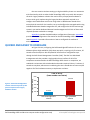
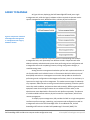
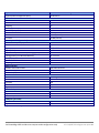
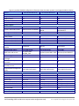
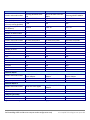
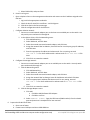
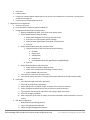
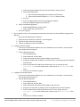
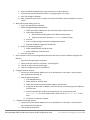
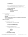
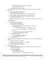
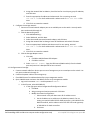
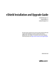
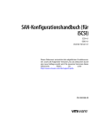
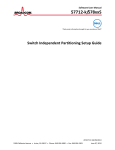
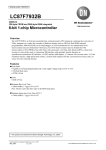
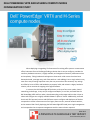
DELL POWEREDGE VRTX AND M-SERIES COMPUTE NODES CONFIGURATION STUDY When deploying or upgrading IT infrastructure for existing office space or a new remote office, businesses face real challenges finding a solution that is easy to configure, provides the necessary hardware resources, is highly available, and mitigates unnecessary maintenance time and complexity. Taking hardware that happens to be around—older servers that have been decommissioned, a storage array, and a few switches—and cobbling it into a single solution may seem like a way of cutting acquisition costs, but can prove to be a false economy. Any savings are offset by hours of effort and headaches to prepare, build, and maintain a legacy hardware solution, not to mention the ongoing risk of aged hardware. In contrast, the Dell PowerEdge VRTX solution, with up to four server nodes, shared networking, and storage, is very easy to configure and deploy. In our labs, we found that the Dell PowerEdge VRTX and four nodes, shared networking, and storage took less than 1 hour to unbox and configure into a highly available VMware® vSphere® cluster. Additionally, we found that it took 78.5 percent less time and 150 fewer steps to configure and deploy out of the box compared to a similar infrastructure on four legacy tower servers, external network switches, and an external SAN. Finally, deploying the Dell PowerEdge VRTX used just a single management tool compared to the six separate management tools the tower solution required. MAY 2013 A PRINCIPLED TECHNOLOGIES TEST REPORT Commissioned by Dell Inc. WHY UPGRADE TO THE DELL POWEREDGE VRTX? The drawbacks of a legacy hardware solution are many. Configuring this solution is time-consuming and may cause prolonged downtime during the setup phase. The aging hardware components may fail when you try to power them, you will likely have to reinstall operating systems from scratch, and compatibility issues often arise. If the legacy hardware lacks built-in redundancy or high-availability features, a failed component can cause unexpected downtime. Last but not least, a group of mismatched components can look cluttered and could create cable management and logistical problems, and takes up more space than a streamlined solution. In addition to configuration drawbacks, repurposing older hardware can also mean having just enough hardware resources to meet current performance demands, with no planning room for future growth. When your resource needs increase—through the steady growth of your business or when workloads peak—you will have to upgrade again. Deploying repurposed gear also forces you to rely on outdated hardware. While it is possible for a piecemeal solution to provide functions similar to those of newer server solutions, such as the Dell PowerEdge VRTX shared infrastructure, it may not provide comparable performance. The administrator who elects to compile a good-enough solution may have to accept reduced performance and frequent hardware service issues which may not be covered by warranties. Finally, a solution consisting of disparate hardware components can be more difficult to manage remotely. For many businesses and remote offices that lack on-site IT administrators, this means that a hardware failure can require the IT admin to travel to the site to troubleshoot. This travel time extends downtime, costing your business money in lost productivity. The streamlined Dell PowerEdge VRTX solution can eliminate the drawbacks of repurposing older gear. You get the performance of Dell PowerEdge 12th generation Mseries server nodes, shared networking, and shared storage in a space-efficient package that is easy to configure and manage. To demonstrate the simplicity and speed of implementing this solution, we had a Dell PowerEdge VRTX shipped to our lab. Upon receipt, we determined the time, steps, and number of separate management tools necessary to configure the Dell PowerEdge VRTX into a four-node VMware vSphere cluster. We also set up a similar infrastructure using four different legacy tower servers, a network switch, and an external SAN. Figure 1 summarizes the differences between the two solutions. Time to set up Number of steps Number of management interfaces Dell PowerEdge VRTX solution 52 minutes 36 seconds 386 1 Legacy hardware solution 4 hours 5 minutes 8 seconds 536 6 Figure 1: Overview of the differences between the two solutions. Dell PowerEdge VRTX and M-series compute nodes configuration study A Principled Technologies test report 2 Our test scenario simulates setting up a high-availability cluster at a remote site with functionality similar to what the Dell PowerEdge VRTX can provide. We compare this with a legacy hardware solution that used a variety of repurposed hardware to meet a similar goal. Implementing the legacy hardware approach required us to configure and troubleshoot each server using either its Web browser-based GUI or native physical console for the interface, set up and configure the managed switch using its dedicated browser-based management GUI, and configure the iSCSI shared storage system in yet another dedicated browser-based management GUI. Each of these tools required separate credentials to manage. Appendix A provides detailed hardware configuration information. Appendix B provides detailed configuration information for the Dell PowerEdge VRTX solution we tested. Appendix C provides information on how we configured the traditional environment. QUICKER AND EASIER TO CONFIGURE As Figure 2 shows, configuring the Dell PowerEdge VRTX solution for use in a VMware vSphere High Availability (HA) cluster was quick, requiring only 52 minutes, 36 seconds of total setup time. We completed all infrastructure configuration steps through the Dell Chassis Management Controller (CMC). The CMC is a Web-based management tool that provides a single graphical user interface for all of the components contained within the Dell PowerEdge VRTX chassis. In comparison, our traditional environment with mixed models and vendors required 4 hours, 5 minutes, 8 seconds to complete, without even considering the time it would take to locate and pull together all of the hardware necessary to implement a solution. Figure 2: The Dell PowerEdge VRTX solution reduced setup time by 78.5 percent compared to the legacy hardware solution. Time (hours:minutes) 5:00 Time to set up (lower numbers are better) 4:05:08 4:00 3:00 2:00 1:00 0:52:36 Dell PowerEdge VRTX solution Dell PowerEdge VRTX and M-series compute nodes configuration study Legacy hardware solution A Principled Technologies test report 3 An added challenge of repurposing older hardware is that you are more likely to experience issues with the hardware components from the very beginning. In our testing, the time spent configuring the legacy hardware solution included approximately 1 hour allocated to troubleshooting hardware issues, which included memory errors, boot drive errors, and installing an additional NIC into the legacy tower servers. Ongoing reliability is a concern with older hardware. There is a risk that the aging hardware components may fail under the load of modern operating systems and applications, causing additional downtime and troubleshooting. New hardware, designed for a modern workload, is less likely to fail. Additionally, as Figure 3 shows, we found that the Dell PowerEdge VRTX solution took 150 fewer steps to configure and deploy out of the box compared to the legacy hardware solution, which used four legacy tower servers, external network switches, and an external SAN. 600 Number of steps (lower numbers are better) 536 500 400 Figure 3: The Dell PowerEdge VRTX solution took 28.0 percent fewer steps than the legacy hardware solution. 386 300 200 100 0 Dell PowerEdge VRTX solution Legacy hardware solution The Dell PowerEdge VRTX solution lets you save on administrative costs and downtime costs to implement the solution. It does not have to be configured on site. Traditional deployment using a legacy hardware solution would require an administrator to travel to the remote office location and configure everything there. In contrast, the Dell PowerEdge VRTX allows for a turnkey deployment approach—after an IT administrator configures the solution at headquarters or a centralized location, it can be delivered to a remote office ready to be plugged in by any on-site employee. For a larger business considering deployments to multiple offices, the savings potential is even greater. Dell PowerEdge VRTX and M-series compute nodes configuration study A Principled Technologies test report 4 EASIER TO MANAGE As Figure 4 shows, deploying the Dell PowerEdge VRTX used just a single management tool, while the legacy hardware solution required six separate vendorspecific management tools, Web-based GUIs, or direct physical connections. Figure 4: Comparison of the Dell PowerEdge VRTX management vs. management with a legacy hardware solution. A piecemeal or separate component solution means dealing with multiple management tools, each potentially from different vendors. Disparate tools mean added complexity and administrative time when performing various configuration and management tasks such as updating firmware, making configuration changes, or troubleshooting issues. Among the other management headaches you face with a piecemeal solution is the fact that while each individual server or infrastructure device has either an out-ofband (OOB) connection or a management connection that provides an interface for performing certain configuration and management functions, there is no consistency in layout and no single sign-on for management. This makes secure storage of credentials very important. Administrators must log into each device separately, locate the specific items they need to address, and execute those tasks manually. Different generations of equipment mean that no single firmware set can address all of the nodes, so the administrator must download the firmware for each platform separately. The absence of a Web-enabled interface makes a physical connection a requirement, which limits remote management. To simplify system management, Dell provides the CMC as a single management interface to perform storage, networking, and compute node configuration as well as management tasks on the Dell PowerEdge VRTX. As an additional tool, the Dell PowerEdge VRTX solution includes Dell OpenManage™ Essentials (OME). This Dell PowerEdge VRTX and M-series compute nodes configuration study A Principled Technologies test report 5 management software provides administrators with an intuitive interface that lets them monitor device status, update firmware and drivers, create their own command-line tasks, and handle other management functions, all from a single portal. Dell OME is free to download from the Dell Support Site. SMALLER FOOTPRINT By eliminating the need for external storage and switches, and accommodating up to four server nodes, the footprint of the Dell PowerEdge VRTX is much smaller than that of traditional multi-server configurations. Requiring only 2.43 square feet of floor space, the Dell PowerEdge VRTX fits easily under a desk in a small office setting. Infrastructure requirements, such as power connections and network cabling, are minimal; our test environment required a single connection to the office network and only four 110v power outlets. By contrast, the four tower systems alone in our legacy solution required 5.54 square feet of floor space, about 228 percent more space than the Dell PowerEdge VRTX. Because the towers were different heights, the external storage and switch had to rest on a nearby surface, making under-the-desk placement unlikely. Because each device required at least one connection to a power outlet, our test setup used eight 110v outlets, twice the number required by the Dell PowerEdge VRTX. ALL-IN-ONE SHARED INFRASTRUCTURE The Dell PowerEdge VRTX solution with M-series compute nodes is an all-in-one solution designed to handle the performance needs of your small-to medium-business or remote office. Here, we provide information about each of the components we used as part of this solution. About the Dell PowerEdge VRTX The Dell PowerEdge VRTX is a compact, all-in-one solution in a 5U rack-able tower chassis. Designed to be quiet under normal operating conditions, the Dell PowerEdge VRTX can be stowed under a desk in a small office without disrupting conversations. Its four bays house M520 or M620 compute nodes, providing a spacesaving alternative to having four separate tower or rack servers. In addition to space savings, the Dell PowerEdge VRTX provides administrators with a unified interface, the Chassis Management Controller, for performing routine systems management tasks. The Dell PowerEdge VRTX chassis supports up to 48 TB of shared internal storage that is presentable as virtual drives to single or multiple compute nodes, and provides optional Dell PowerEdge VRTX with 12 3.5-inch drives Dell PowerEdge VRTX with 25 2.5-inch drives pass-through and eight PCIe slots for additional device connectivity. The chassis integrated storage can be configured with 25 bays for 2.5-inch drives or with 12 bays for 3.5-inch drives. The Dell PowerEdge VRTX integrated switch contains multiple external network ports for easy expansion or integration into any computing environment. Dell PowerEdge VRTX and M-series compute nodes configuration study A Principled Technologies test report 6 For more information about the Dell PowerEdge VRTX, visit www.dell.com/poweredge. About the Dell PowerEdge M620 compute nodes The Dell PowerEdge M620, a half-height compute node, has features optimized for performance, density, and energy efficiency. Processors. The Dell PowerEdge M620 is powered by two Intel® Xeon® E52600-series processors, which incorporate the very latest in processor technology from Intel. The powerful processors provide the performance you need for your essential mainstream tasks. The Intel Xeon E5-2600-series processor gives you up to eight cores per processor, or up to 16 cores per server. Memory. The Dell PowerEdge M620 holds up to 768GB DDR3 RAM (up to 1600 MHz) across 24 DIMM slots per compute node. Management. The Dell PowerEdge M620, like all late-model Dell servers, comes with the Dell Lifecycle Controller. This tool simplifies server management by providing a single interface for management functions and by storing critical system information in the system itself. There are no CDs or USB keys to keep track of for drivers or firmware. About the Intel Xeon processor E5 family The new Intel Xeon processor E5 family, which comes standard in new Dell PowerEdge servers, incorporates new technology and features to meet the computing demands of the present and future. The Intel Xeon processor E5 family delivers intelligent and adaptive performance using such features as Intel Turbo Boost Technology 2.0, Intel Advanced Vector Extension, Intel Integrated I/O, and Intel Data Direct I/O Technology. These new processors also feature Intel Trusted Execution Technology (Intel TXT) and utilize Intel Advance Encryption Standard New Instructions (Intel AES-NI) to help keep your data safe. For more information about the Intel Xeon processor E5 family visit www.intel.com. About VMware vSphere 5 vSphere 5 is the latest virtualization operating system from VMware. vSphere 5 virtualizes server, storage, and networking resources, achieving a consolidation ratio greater than 15:1. Features such as automated management and dynamic resource allocation improve efficiency. The services that vSphere 5 provides fall into two categories: infrastructure services and application services. The former handle the virtualization of resources and their allocation to application when most needed, while the latter provide service-level controls to applications running on vSphere 5. Dell PowerEdge VRTX and M-series compute nodes configuration study A Principled Technologies test report 7 To learn more about VMware vSphere 5, visit www.vmware.com/products/vsphere/overview.html. IN CONCLUSION When considering whether to upgrade to the new Dell PowerEdge VRTX or repurpose older hardware, the advantages of new hardware are clear. Not only do you get newer hardware that is faster and is better-equipped to handle the increasing demands of today’s business applications and workloads, but you also benefit from advances that make deployment and management easier than ever. In our labs, we compared the Dell PowerEdge VRTX with four server nodes and shared storage and networking to a similar infrastructure using four legacy tower servers, external network switches, and an external SAN. Our testing revealed the following: PowerEdge VRTX took 78.5 percent less time and 150 fewer steps to configure and deploy out of the box compared to the legacy solution. PowerEdge VRTX It took less than 1 hour to unbox and configure into a highly available VMware vSphere cluster compared to over 4 hours on the legacy solution. Deploying the Dell PowerEdge VRTX used just a single management tool, the integrated Chassis Management Controller, whereas the tower solution required six separate management tools. Choosing such a complete solution during your next server refresh can simplify infrastructure setup and configuration, boost performance through built-in high availability features, and potentially save your organization space and operating costs over the life of the hardware. Dell PowerEdge VRTX and M-series compute nodes configuration study A Principled Technologies test report 8 APPENDIX A – DETAILED CONFIGURATION INFORMATION Figure 5 provides detailed configuration information about the Dell PowerEdge VRTX solution we set up. System Enclosure Compute node enclosure General dimensions of compute node enclosure Height (inches) Width (inches) Depth (inches) U size in server rack (U) Power supplies Total number Vendor and model number Wattage of each (W) Cooling fans Total number Vendor and model number Dimensions (h x w) of each Volts Chassis RAID controller Vendor and model number Firmware version Cache size (GB) Chassis shared hard drives Vendor and model number Number of drives Size (TB) RPM Type Chassis USB ports Number Type Platform Vendor and model number Motherboard model number Motherboard chipset BIOS name and version BIOS settings General Number of processor packages Number of cores per processor Number of hardware threads per core Dell PowerEdge VRTX solution Dell PowerEdge VRTX 8 19 29.5 5 4 Dell 80 Plus Platinum E1100E-S0 (P/N 0YT39Y) 1,100 6 Delta Electronics, Inc. 60mm x 60mm 12 Dell SPERC8 23.8.2-0005 1 Dell (Seagate Technologies®) Constellation ES.3 5 3 7.2K SAS 6 Gbps 2 2.0 Dell PowerEdge M620 0VHRN7A05 Intel C600 Dell BIOS 1.7.0 Default 2 6 2 Dell PowerEdge VRTX and M-series compute nodes configuration study A Principled Technologies test report 9 System System power management policy CPU Vendor Name Stepping Socket type Core frequency (GHz) L1 cache L2 cache L3 cache Memory modules (per node) Total RAM in system (GB) Vendor and model number Type Speed (MHz) Speed in the system currently running @ (MHz) Timing/latency (tCL-tRCD-iRP-tRASmin) Size (GB) Number of RAM modules Chip organization RAID controller Vendor and model number Firmware version Cache size (GB) Hard drive Vendor and model number Number of drives Size (GB) RPM Type Network adapter Vendor and model number Type Number of ports USB ports (per node) Number Type Dell PowerEdge VRTX solution Performance Intel Xeon E5-2620 C2 Socket 2011 LGA 2.00 32 KB (per core) 256 KB (per core) 15 MB (shared) 32 Hynix Semiconductor HMT31GR7CFR4C-PB DDR3-12800 1,600 1,333 11-11-11-35 8 4 Double-sided Dell PERC H310 mini 20.12.0-0004 0 MB Dell Seagate® Constellation.2™ 2 250 7.2K SATA Broadcom® NetXtreme® II 10 Gb Ethernet BCM57810 Embedded 2 3 2.0 Figure 5: Detailed configuration information for the Dell PowerEdge VRTX solution. Dell PowerEdge VRTX and M-series compute nodes configuration study A Principled Technologies test report 10 Figures 6 provides detailed configuration information about the tower systems in our legacy hardware solution. HP ProLiant ML310 G5 14.4 6.9 16.8 4 17.0 7.9 24.0 5 17.5 8.6 28.5 5 1 Vendor and model number Delta Electronics DPS300AB Wattage of each (W) Cooling fans Total number Vendor and model number Dimensions (h x w) of each Volts General Motherboard model number Motherboard chipset 300 1 Delta Electronics DPS410DB 410 1 HP Switching Power Supply DPS-800GB A 850 1 HP 576930-001 92 mm x 25 mm 12 1 HP 459188-001 120 mm x 25 mm 12 3 Nidec Beta V35633-94 130 mm x 125 mm 12 576924-001 A61TR1 434719-001 Intel 3400 Chipset HP System BIOS 0270126_TAN Performance Intel 3210 Chipset Intel C600 ProLiant System BIOS - W05 ProLiant System BIOS P57 Performance Performance 1 1 2 4 4 4 2 1 1 Static High Performance Static High Performance Static High Performance Intel Xeon X3460 B1 LGA 1156 2.80 32 KB (per core) 256 KB (per core) 8 Intel Xeon X3370 E0 LGA 775 3.00 32 KB (per core) 12 MB (shared) N/A Intel Xeon E5450 E0 LGA 771 3.00 32 KB (per core) 12 MB (shared) N/A 8 4 32 BIOS name and version BIOS settings Number of processor packages Number of cores per processor Number of hardware threads per core System power management policy CPU Vendor Name Stepping Socket type Core frequency (GHz) L1 cache L2 cache L3 cache (MB) Memory modules Total RAM in system (GB) HP ProLiant ML110 G6 HP ProLiant ML370 G5 Server General dimensions of server Height (inches) Width (inches) Depth (inches) U size in server rack (U) Power supplies Total number Dell PowerEdge VRTX and M-series compute nodes configuration study A Principled Technologies test report 11 Server Vendor and model number Type Speed (MHz) Speed in the system currently running @ (MHz) Timing/latency (tCL-tRCDiRP-tRASmin) Size (GB) Number of RAM modules Chip organization RAID controller Vendor and model number Cache size (MB) Hard drive #1 Vendor and model number Number of drives Size (GB) RPM Type Hard drive #2 Vendor and model number Number of drives Size (GB) RPM Type Network adapter Vendor and model number Type Number of ports Network adapter 2 HP ProLiant ML110 G6 Samsung M391B5673EH1CH9 PC3-10600E DDR3 1,333 HP ProLiant ML310 G5 Micron MT18HTF25672AY800E1 PC2-6400E DDR2 800 1,333 800 666 9-9-9-24 6-6-6-18 5-5-5-15 2 4 Double-Sided 2 2 Double-sided 4 8 Double-sided HP Smart Array B110i N/A HP Smart Array E200 128 HP Smart Array P400 256 Hitachi HDS721032CLA362 1 320 7.2K SATA HP DF0792A9844 2 72 15K SAS HP EG0146FAWHU 2 146 10K SAS N/A N/A N/A N/A N/A ST500NM001 2 500 7.2 SAS N/A N/A N/A N/A N/A Intel Pro/1000 PT Dual Port Server Adapter PCIe 2 Intel Pro/1000 PT Server Adapter PCIe 1 Intel Pro/1000 PT Dual Port Server Adapter PCIe 2 N/A 4 2.0 Vendor and model number HP NC 107i PCIe Gigabit Type Number of ports USB ports (per node) Number Type Integrated 1 Intel (R) Pro/1000 PT Server Adapter PCIe 1 6 2.0 2 2.0 HP ProLiant ML370 G5 Samsung M395T5160QZ4 DDR2-5300F 666 N/A N/A Figure 6: Detailed configuration information for the towers in the legacy hardware solution. Dell PowerEdge VRTX and M-series compute nodes configuration study A Principled Technologies test report 12 Figures 7 provides detailed configuration information about the storage and switch in our legacy hardware solution. Storage array Number of arrays Number of active storage controllers Number of active storage ports Switch number/type/model Power supplies Power supply vendor and model Number of drives Drive vendor and model number Drive size (GB) Drive buffer size (MB) Drive RPM Drive type Drive firmware Switch Ports Port speed Model number HP P2000 G3 Modular Smart Array System 1 2 4 P2000 G3 2 3Y Power Technologies YM-3159A AR Rev A 24 HP EH0072FARUA 72 16 15,000 6G SAS HPD3 NETGEAR® ProSAFE® Smart Switch 24 10mbps / 100mbps / 1000mbps GS724T v2 Figure 7: Detailed configuration information for the storage array and network switch. Dell PowerEdge VRTX and M-series compute nodes configuration study A Principled Technologies test report 13 APPENDIX B – CONFIGURING THE DELL POWEREDGE VRTX SOLUTION Configuring the VRTX network 1. 2. 3. 4. 5. 6. 7. 8. 9. 10. 11. 12. 13. 14. 15. Open a Web browser, and enter the address listed for the CMC IP on the front LCD display. Log in with the appropriate credentials. Expand I/O Module Overview. Click Gigabit Ethernet. Click the Properties tab. Click the Launch I/O Module GUI button. Log in with the username root and the password calvin. These are the default credentials for the integrated switch module. Click Submit. We recommend changing the password for deployment in a production environment. To change the password after first login, expand SystemManagement SecurityLocal User Database, and at the top of the page, select Edit. Expand SwitchingVLAN, and click VLAN Membership. Under the VLAN Membership tab, click Add. a. Enter a VLAN ID number (1000). b. Enter a VLAN Name (vMotion). c. Click Apply. Click SwitchingVLANPort Settings. Under the Port Settings tab, click Edit. a. Select the Internal Port radio button. b. After the screen populates, use the pull-down menu to select gi1/2. c. In VLAN list, click 1, and click Remove. d. Enter 1000 in the VLAN list box, and click Add. e. Click Apply. f. Use the drop-down menu to select gi2/2. g. In the VLAN list, click 1, and click Remove. h. Enter 1000 in the VLAN list, and click Add. i. Click Apply. Click the floppy drive icon in upper-right portion of the configuration pane to save all new settings to start-up configuration. Click Log out. Click OK. Configuring the VRTX shared storage 1. 2. 3. 4. 5. Open a Web browser, and enter the address listed for the CMC IP on the front LCD display. Log in with the appropriate credentials. Expand Storage. Click Storage. Click the Setup tab. a. Under Assignment Mode, select the radio button for Multiple Assignment, and click Apply. Dell PowerEdge VRTX and M-series compute nodes configuration study A Principled Technologies test report 14 b. Click OK to confirm the message box indicating Operation Successful. 6. Configure virtual disks: a. Click StorageVirtual Disks. b. On the Virtual Disks tab, click Create. i. For Choose a virtual disk type, select the appropriate RAID level. For our testing, we selected RAID 10. ii. Scroll down to select the appropriate physical disks (for our testing 0:0:0 – 0:0:3). iii. Accept the default size, and click Create Virtual Disk. iv. Click OK to confirm the message box indicating Operation Successful. c. On the Virtual Disks tab, click Manage. i. Select the Virtual Disks Action pull-down menu for Virtual Disk 0 and select the appropriate initialization option. Please note that if you select Initialize: Fast, the RAID adapter may run a background initialization, which will cause a slight decrease in I/O performance until the initialization completes. ii. Click Apply. iii. Click OK to confirm the message box indicating Operation Successful once the initialization completes. iv. Select the Virtual Disks Action pull-down menu for Virtual Disk 0 and select Assign Dedicated Hot spare. For our testing, we selected Unassigned Physical Disk 0:0:4. v. Click Apply. vi. Click OK to confirm the message box indicating Operation Successful. d. In this step, we will allow shared LUN access to both compute nodes. On the Virtual Disks tab, click Assign. i. Use the pull-down menu for Virtual Disk 0 and SLOT-01, and select Full Access. ii. Use the pull-down menu for Virtual Disk 0 and SLOT-02, and select Full Access. iii. Click Apply. iv. Click OK to confirm the message box indicating Operation Successful. Configuring VRTX server nodes Configuring VMware vSphere (ESXi) embedded on server nodes 1. Open a Web browser, and enter the address listed for the CMC IP on the front LCD display. 2. Log in with the appropriate credentials. 3. Expand Server Overview, and select Slot-01. 4. Click the Setup Tab. Perform the following steps in the iDRAC settings: a. Check the box for Enable LAN. b. Check the box for Enable IPv4. c. Check the box for DHCP. d. Check the box for IPMI Over LAN. e. Click Apply iDRAC Network Settings. f. To confirm changes to the iDRAC network settings, click OK. 5. Click the Power Tab. a. Select Power On Server. Dell PowerEdge VRTX and M-series compute nodes configuration study A Principled Technologies test report 15 6. 7. 8. 9. 10. 11. 12. b. Click Apply. c. To confirm server control action, click OK. d. To confirm operation was successful, click OK. Click the Properties tab. Click Launch Remote Console. On new browser page, click Continue to website (not recommended) if prompted. a. If a message appears indicating a pop-up was blocked, select Always allow pop-ups from this site. b. Close the browser tab for the iDRAC. c. Click Launch Remote Console. d. If a message appears indicating the Web page wants to run an add-on called “Virtual Console from Dell Inc.,” select Allow for all websites. A new window appears showing the console for the server to configure. Select PowerReset System. Change the boot disk order in System Setup. a. When prompted during POST, press F2 to enter System Setup. b. Click BIOS. c. Click Boot Settings. d. Click BIOS Boot Settings. e. Scroll down, and click Hard Disk Drive Sequence. i. Highlight the entry for SD card or USB drive, and move it to the top using the + key. ii. Click OK. f. Click Back twice. g. Click Finish. h. Click Yes. i. Click Finish. j. Click OK. The system will restart. Complete configuration of ESXi host: a. Press F2 to configure. b. Enter the root account password, and press Enter. c. Select Configure Management Network, and press Enter. d. Select Network Adapters, and press Enter. i. Clear the checkbox for vmnic0. ii. Check the checkbox for vmnic1. iii. Press Enter. e. Press Esc. f. To restart networking, press Y. g. Select Troubleshooting Options. i. Select Enable ESXi shell, and press Enter. ii. Select Enable SSH, and press Enter. iii. Press Esc. h. To log out, press Esc. Repeat above Server Setup steps for each additional server you wish to configure. Dell PowerEdge VRTX and M-series compute nodes configuration study A Principled Technologies test report 16 Configuring VRTX vSphere environment We performed all downloads prior to executing these steps. Download times will vary. 1. Configure Slot 1 host: a. Open a new vSphere client session, and connect to the IP address for the server in Slot 1. i. Log in with root and the password you configured during ESXi installation. b. Add shared storage. i. Click the Host configuration tab. ii. Click the Storage menu. 1. Click Add Storage… 2. Select Disk/LUN, and click Next. 3. Select Local Dell Disk, and click Next. 4. Select VMFS-5, and click Next. 5. Review the disk layout, and click Next. 6. Enter an appropriate datastore name. For our testing, we selected VRTX-Shared-01. Click Next. 7. Accept maximum space available, and click Next. 8. Click Finish to begin Formatting and addition to node. c. Configure vMotion network i. Click the Networking menu. 1. Click Add Networking… 2. Select VMkernel, and click Next. 3. Select the unused network adapter, and click Next. 4. Assign the network label as vMotion, check the box for Use this port group for vMotion, and click Next. 5. Enter the appropriate IP address and subnet mask. For our testing, we used192.168.0.50 for the IP address with a subnet mask of 255.255.255.0. Click Next. 6. Click Finish to create the network. 2. Configure Slot 2 host: a. Open a new vSphere client session, and connect to the IP address for the server in Slot 2. i. Log in with root and the password you configured during ESXi installation. b. Add shared storage: i. Click the Host Configuration tab. ii. Click the Storage menu. 1. The new storage should appear automatically. If no storage is listed, click Rescan All… 2. Click OK to rescan all adapters. The shared storage will appear automatically with the name VRTX-shared-01 already configured. c. Configure vMotion network: i. Click the Networking menu. 1. Click Add Networking… 2. Select VMkernel, and click Next. 3. Select the unused network adapter, and click Next. Dell PowerEdge VRTX and M-series compute nodes configuration study A Principled Technologies test report 17 4. Assign the network label as vMotion, check the box for Use this port group for vMotion, and click Next 5. Enter the IP address and subnet mask. For our testing, we used 192.168.0.51 for the IP address and255.255.255.0 for the subnet mask. Click Next. ii. Click Finish to create the network. 3. Install and configure vCenter Server: a. Install the vCenter appliance: i. In the vSphere client, select FileDeploy OVF Template. ii. Browse to the location of the vCenter Server Appliance .ovf file, and click Open. iii. In the OVF Template Details page, click Next. iv. In Name and Location, enter vCenter Server for the name, and click Next. v. Select VRTX-shared-01, and click Next. vi. Select a disk format, and click Next. vii. Check the box for Power on after deployment, and click Finish. b. Configure the vCenter appliance: i. Right-click the new vCenter, and select Open Console. ii. Note the instructions and the address to use for configuration. iii. Open a Web browser to the address listed in the console. iv. Log in with root and the password vmware. v. Check the box for accept license agreement, and click Next. vi. Select the radio button for Configure with default settings, and click Next. vii. Click Start. Setup will complete and a new database will be configured automatically. viii. Click the Admin Tab. 1. Enter vmware in the current administrator password section. 2. Enter a new password into both password fields. 3. Click Change Password. c. Add both server nodes to the vCenter: i. Open a new vSphere client session, and connect to the IP address assigned to the vCenter Server Appliance during installation. ii. Log in with root and the password you provided during setup. iii. Create a new datacenter: 1. Right-click the item at the top of the left hand pane in the client, and select New Datacenter. 2. Select an appropriate name for the Datacenter. For our testing, we selected VRTX-01. iv. Add each host to the Datacenter: 1. Right-click VRTX-01, and select Add Host. 2. Enter the IP address of the ESXi host in Slot 1. 3. Enter the username root and the password you assigned the host during setup. 4. Click Next. 5. Click Yes to verify the authenticity and complete the import. 6. Click Next. 7. Select a license to assign, and click Next. Dell PowerEdge VRTX and M-series compute nodes configuration study A Principled Technologies test report 18 8. Do not check Enable Lockdown Mode, and click Next. 9. Click Next. 10. Click Finish. 11. Repeat steps 1 through 10 for the ESXi host in Slot 2. 4. Set up a high availability cluster: a. Create a vSphere HA cluster: i. Right-click the VRTX-01 Datacenter. ii. Select New Cluster. iii. Name the cluster. For our testing, we used VRTX-01-C1. iv. Check the box for Turn On vSphere HA, and click Next. v. Accept all vSphere HA defaults, and click Next. vi. Accept Virtual Machine Options defaults, and click Next. vii. Accept VM Monitoring defaults, and click Next. viii. Accept VMware EVC defaults, and click Next. ix. Accept VM Swapfile Location defaults, and click Next. x. Click Finish to create the cluster. b. Click and drag each ESXi host into the cluster to populate it. Dell PowerEdge VRTX and M-series compute nodes configuration study A Principled Technologies test report 19 APPENDIX C – CONFIGURING THE TRADITIONAL ENVIRONMENT 1. Set up network: a. Connect power. b. Connect to switch Web interface: i. Attach to switch with a network cable. ii. Assign the workstation NIC IP address 192.168.0.25. iii. Open Web browser 192.168.0.239 (the default address). iv. In the password field, type password and press Enter. c. Configure vMotion VLAN: i. In the left pane, click VLAN. ii. Select the radio button for IEEE802.1q VLAN and click OK. iii. In the pull-down menu in the right pane, select Add new VLAN. iv. In the VLAN ID field, type 1000. v. Click the empty box for each port to tag with VLAN 1000. The box will be marked with a T. For our testing, we used ports 13-16. Click Apply. d. Configure Storage Network VLAN: i. In the pull-down menu in the right pane, select Add New VLAN. ii. In the VLAN ID field, type 2000. iii. Click the empty box for each port to tag with VLAN 2000. The box will be marked with a T. For our tests, we selected ports 19-22. Click Apply. e. Enable Jumbo Frames (for iSCSI network): i. In the left pane, click Advanced. ii. Click Jumbo Frames iii. In the right pane, select the radio button for Enable and click Apply. f. Back up the network configuration: i. In the left pane, click Configuration Backup. ii. In the right pane, click Backup. A file will be downloaded to your workstation, which can be used to restore the switch if necessary. g. Log out and disconnect from switch: i. In the left pane, click Logout. ii. Disconnect the management workstation from the switch. iii. Change your management workstation network adapter address back to its previous configuration. 2. Prepare the HP ML110 G6 host: a. Open case of tower. b. Locate internal USB port and insert 4GB USB drive. c. Close case. d. Connect power. e. Connect an unused network adapter port on the server to an unused port on the switch. Use only ports numbered 1 – 12. Dell PowerEdge VRTX and M-series compute nodes configuration study A Principled Technologies test report 20 f. Connect monitor and keyboard to server. 3. Configure the HP ML110 G6 hardware: a. Power on the server. b. Insert installation media into optical media drive. c. Change the boot disk order in System Setup: i. When prompted during POST, press F10 to enter System Setup. ii. Select Advanced. 1. Select Processor Power Efficiency, and press Enter. 2. Select Performance, and press Enter. iii. Select Boot from the top menu. iv. Change the boot order. 1. CD-ROM Drive 2. Removable Devices 3. Hard Drive a. USB b. HP Smart Array 4. Embedded NIC1 v. Select Exit from the top menu. vi. Select Exit Saving Changes and press Enter. vii. Select Yes, and press Enter to save configuration changes and exit. d. The system will reboot and load the ESXi installation media. 4. Install ESXi: a. Press Enter to begin install when prompted. i. Press F11 to accept license agreement. ii. Select USB drive for installation target, and press Enter to confirm selection. iii. Select US Default Keyboard Layout, and press Enter to confirm selection. iv. Type the new root password and confirm it by typing it again. Press Enter. v. Press F11 to begin installation. b. After completion, press Enter to reboot, remove installation media, and wait for return to service. 5. Configure ESXi: a. When ESXi finishes loading, press F2. b. Log in with appropriate credentials. c. Select Configure Management Network. i. Select the network adapter with the connected status, and press Enter. d. Select DNS configuration. i. Select Use the following DNS server address and hostname: ii. Type a new hostname (example: HP-ESX01), and press Enter. iii. Press Esc. e. Press Y to apply changes and restart management network. f. Note the IP address assigned to the ESX host. g. Select Troubleshooting Options. i. Select EnableESXi Shell, and press Enter. Dell PowerEdge VRTX and M-series compute nodes configuration study A Principled Technologies test report 21 ii. Select Enable SSH, and press Enter. h. Press Esc to log out. i. Open a vSphere client on the management workstation and connect to the IP address assigned to the ESX host. i. Log in with the appropriate credentials. ii. Check the box for install this certificate… and click Ignore. iii. Click OK to dismiss the license message. iv. Click the configuration tab for the ESX host. j. Configure vMotion network: i. Connect an unused network adapter port on the host to an available port on the switch. Use only switch ports numbered 13 through 18. ii. In the vSphere client, click the Networking menu. 1. Click Add Networking… 2. Select VMkernel, and click Next. 3. Select the unused connected network adapter, and click Next. 4. Assign the network label as vMotion, check the box for Use this port group for vMotion, and click Next. 5. Enter the appropriate IP address and subnet mask. For our testing, we used 192.168.0.150 for the IP address with a subnet mask of 255.255.255.0. Click Next. 6. Click Finish to create the network. k. Configure the storage network: i. Connect an unused network adapter port to an available port on the switch. Use only switch ports numbered 19 through 24. ii. Click the Networking menu. 1. Click Add Networking… 2. Select VMkernel, and click Next. 3. Select the unused connected network adapter, and click Next. 4. Assign the network label as Storage. Leave all checkboxes unchecked. Click Next. 5. Enter an appropriate IP address and subnet mask. For our testing, we used 192.168.1.50 for the IP address with a subnet mask of 255.255.255.0. Click Next. 6. Click Finish to create the network. iii. Click the Storage Adapters menu. 1. Click Add. a. Click OK to Add Software iSCSI Adapter. b. Click OK to confirm. 2. Select vmhba35 (iSCSI). Copy the iSCSI name (WWN number) from the details pane and paste into a notepad file for later retrieval. 6. Prepare the HP ML370 G5 host: a. Open case of tower. b. Locate internal USB port and insert 4GB USB drive. Dell PowerEdge VRTX and M-series compute nodes configuration study A Principled Technologies test report 22 c. Close case. d. Connect power. e. Connect an unused network adapter port on the server to an unused port on the switch. Use only ports numbered 1 through 12. f. Connect monitor and keyboard to server. 7. Begin ESXi host configuration: a. Power on the server. b. Insert installation media into optical media drive. c. Change the boot disk order in System Setup. i. When prompted during POST, press F9 to enter System Setup. ii. Select System Options, and press Enter. 1. Select Power Regulator for ProLiant, and press Enter. 2. Press Enter to confirm power profile message. 3. Select HP Static High Performance Mode, and press Enter. 4. Press Esc. iii. Select Standard Boot Order (IPL), and press Enter. 1. Change the order of the of the devices to the following: a. CD-ROM b. Floppy Drive c. USB DriveKey d. Hard Drive C: e. PCI Embedded HP NC373i Multifunction Gigabit Adapter 2. Press Esc. iv. Select Advanced Options and press Enter. 1. Select Processor Options, and press Enter. 2. Select Intel® Virtualization Technology, and press Enter. 3. Select Enabled, and press Enter. v. Press Esc four times to exit the setup utility. vi. Press F10 to confirm exit utility. The system will restart and boot to the ESXi installer media. d. Install ESXi: i. Press Enter to begin install when prompted. ii. Press F11 to accept license agreement. iii. Select USB drive for installation target, and press Enter to confirm selection. iv. Select US Default Keyboard Layout, and press Enter to confirm selection. v. Type the new root password, and confirm it by typing it again. Press Enter. vi. Press F11 to begin installation. vii. After completion, press Enter to reboot, remove the installation media, and wait for return to service. e. ESXi Basic configuration i. When ESXi finishes loading, press F2. ii. Log in with appropriate credentials. iii. Select Configure Management Network. Dell PowerEdge VRTX and M-series compute nodes configuration study A Principled Technologies test report 23 1. Select the network adapter with the connected status, and press Enter. 2. Select DNS configuration. a. Select Use the following DNS server address and hostname: b. Type a new hostname (example: HP-ESX02), and press Enter. 3. Press Esc. 4. Press Y to apply changes, and restart management network. 5. Note the IP address assigned to the ESX host. iv. Select Troubleshooting Options. 1. Select EnableESXi Shell, and press Enter. 2. Select Enable SSH, and press Enter. v. Press Esc to log out. f. Open a vSphere client on the management workstation and connect to the IP address assigned to the ESX host. i. Log in with the appropriate credentials. ii. Check the box for install this certificate… and click Ignore. iii. Click OK to dismiss the license message. iv. Click the configuration tab for the ESX host. g. Configure vMotion network: i. Connect an unused network adapter port to an available port on the switch. Use only switch ports numbered 13 through 18. ii. Click the Networking menu. 1. Click Add Networking… 2. Select VMkernel, and click Next. 3. Select the unused connected network adapter, and click Next. 4. Assign the network label as vMotion, check the box for Use this port group for vMotion, and click Next. 5. Enter the appropriate IP address and subnet mask. For our testing, we used 192.168.0.151 for the IP address with a subnet mask of 255.255.255.0. Click Next. 6. Click Finish to create the network. h. Configure the storage network i. Connect an unused network adapter port to an available port on the switch. Use only switch ports numbered 19 through 24. ii. Click the Networking menu. 1. Click Add Networking… 2. Select VMkernel, and click Next. 3. Select the unused connected network adapter, and click Next. 4. Assign the network label as Storage. Leave all checkboxes unchecked. Click Next. 5. Enter an appropriate IP address and subnet mask. For our testing, we used 192.168.1.151 for the IP address with a subnet mask of 255.255.255.0. Click Next. 6. Click Finish to create the network. Dell PowerEdge VRTX and M-series compute nodes configuration study A Principled Technologies test report 24 iii. Click the Storage Adapters menu. 1. Click Add. a. Click OK to Add Software iSCSI Adapter. b. Click OK to confirm. 2. Select vmhba36 (iSCSI). Copy the iSCSI name (WWN number) from the details pane and paste into a notepad file for later retrieval. 8. Prepare the HP ML310 G5 ESXi host: a. Open case of tower. b. Locate internal USB port and insert 4GB USB drive. c. Close case. d. Connect power. e. Connect an unused network adapter port on the server to an unused port on the switch. Use only ports numbered 1 through 12 f. Connect monitor and keyboard to server. 9. Prepare the HP ML310 G5 ESXi host: a. Power on the server. b. Insert installation media into optical media drive. c. Change the boot disk order in System Setup i. When prompted during POST, press F9 to enter System Setup. ii. Select System Options, and press Enter. 1. Select Power Regulator for ProLiant, and press Enter. 2. Press Enter to confirm power profile message. 3. Select HP Static High Performance Mode, and press Enter. 4. Press Esc. iii. Select Standard Boot Order (IPL) and press Enter. 1. Change the order of the of the devices to the following: a. CD-ROM b. Floppy Drive c. USB DriveKey d. Hard Drive C: e. PCI Embedded HP NC373i Multifunction Gigabit Adapter 2. Press Esc. iv. Select Advanced Options and press Enter. 1. Select Processor Options and press Enter. 2. Select Intel® Virtualization Technology and press Enter. 3. Select Enabled and press Enter. v. Press Esc four times to exit the setup utility. vi. Press F10 to confirm exit utility. The system will restart and boot to the ESXi installer media. d. Install ESXi i. Press Enter to begin install when prompted. ii. Press F11 to accept license agreement. iii. Select USB drive for installation target, and press Enter to confirm selection. Dell PowerEdge VRTX and M-series compute nodes configuration study A Principled Technologies test report 25 iv. v. vi. vii. Select US Default Keyboard Layout, and press Enter to confirm selection. Type the new root password and confirm it by typing it again. Press Enter. Press F11 to begin installation. After completion, press Enter to reboot, remove the installation media, and wait for return to service. e. When ESXi finishes loading, press F2. i. Log in with appropriate credentials. ii. Select Configure Management Network. 1. Select the network adapter with the connected status, and press Enter. 2. Select DNS configuration. a. Select Use the following DNS server address and hostname: b. Type a new hostname (example: HP-ESX03), and press Enter. 3. Press Esc. 4. Press Y to apply changes and restart management network. 5. Note the IP address assigned to the ESX host. iii. Select Troubleshooting Options. 1. Select EnableESXi Shell, and press Enter. 2. Select Enable SSH, and press Enter. iv. Press Esc to log out. f. Open a vSphere client on the management workstation and connect to the IP address assigned to the ESX host. i. Log in with the appropriate credentials. ii. Check the box for install this certificate… and click Ignore. iii. Click OK to dismiss the license message. iv. Click the configuration tab for the ESX host. g. Configure vMotion network: i. Connect an unused network adapter port to an available port on the switch. Use only switch ports numbered 13 through 18 ii. Click the Networking menu. 1. Click Add Networking… 2. Select VMkernel, and click Next. 3. Select the unused connected network adapter, and click Next. 4. Assign the network label as vMotion, check the box for Use this port group for vMotion, and click Next. 5. Enter the appropriate IP address and subnet mask. For our testing, we used 192.168.0.152 for the IP address with a subnet mask of 255.255.255.0. Click Next. 6. Click Finish to create the network. h. Configure the storage network: i. Connect an unused network adapter port to an available port on the switch. Use only switch ports numbered 19 through 24. ii. Click the Networking menu. Dell PowerEdge VRTX and M-series compute nodes configuration study A Principled Technologies test report 26 1. 2. 3. 4. 5. Click Add Networking… Select VMkernel, and click Next. Select the unused connected network adapter, and click Next. Assign the network label as Storage. Leave all checkboxes unchecked. Click Next. Enter an appropriate IP address and subnet mask. For our testing, we used 192.168.1.152 for the IP address with a subnet mask of 255.255.255.0. Click Next. 6. Click Finish to create the network. iii. Click the Storage Adapters menu. 1. Click Add. a. Click OK to Add Software iSCSI Adapter. b. Click OK to confirm. 2. Select vmhba35 (iSCSI). Copy the iSCSI name (WWN number) from the details pane and paste into a notepad file for later retrieval. 10. Prepare the HP ML370 G5 host: a. Open case of tower. b. Locate internal USB port and insert 4GB USB drive. c. Close case. d. Connect power. e. Connect an unused network adapter port on the server to an unused port on the switch. Use only ports numbered 1 through 12. f. Connect monitor and keyboard to server. 11. Begin ESXi host configuration: a. Power on the server. b. Insert installation media into optical media drive. c. Change the boot disk order in System Setup. i. When prompted during POST, press F9 to enter System Setup. ii. Select System Options, and press Enter. 1. Select Power Regulator for ProLiant, and press Enter. 2. Press Enter to confirm power profile message. 3. Select HP Static High Performance Mode, and press Enter. 4. Press Esc. iii. Select Standard Boot Order (IPL) and press Enter. 1. Change the order of the of the devices to the following: a. CD-ROM b. Floppy Drive c. USB DriveKey d. Hard Drive C: e. PCI Embedded HP NC373i Multifunction Gigabit Adapter 2. Press Esc. iv. Select Advanced Options, and press Enter. 1. Select Processor Options, and press Enter. Dell PowerEdge VRTX and M-series compute nodes configuration study A Principled Technologies test report 27 2. Select Intel® Virtualization Technology, and press Enter. 3. Select Enabled, and press Enter. v. Press Esc four times to exit the setup utility. vi. Press F10 to confirm exit utility. The system will restart and boot to the ESXi installer media. d. Install ESXi: i. Press Enter to begin install when prompted. ii. Press F11 to accept license agreement. iii. Select USB drive for installation target, and press Enter to confirm selection. iv. Select US Default Keyboard Layout, and press Enter to confirm selection. v. Type the new root password and confirm it by typing it again. Press Enter. vi. Press F11 to begin installation. vii. After completion, press Enter to reboot, remove the installation media, and wait for return to service. e. ESXi basic configuration: i. When ESXi finishes loading, press F2. ii. Log in with appropriate credentials. iii. Select Configure Management Network. 1. Select the network adapter with the connected status, and press Enter. 2. Select DNS configuration. a. Select Use the following DNS server address and hostname: b. Type a new hostname (example: HP-ESX04), and press Enter. 3. Press Esc. 4. Press Y to apply changes and restart management network. 5. Note the IP address assigned to the ESX host. iv. Select Troubleshooting Options. 1. Select EnableESXi Shell, and press Enter. 2. Select Enable SSH, and press Enter. v. Press Esc to log out. f. Open a vSphere client on the management workstation and connect to the IP address assigned to the ESX host. i. Log in with the appropriate credentials. ii. Check the box for install this certificate… and click Ignore. iii. Click OK to dismiss the license message. iv. Click the configuration tab for the ESX host. g. Configure vMotion network: i. Connect an unused network adapter port to an available port on the switch. Use only switch ports numbered 13 through 18. ii. Click the Networking menu. 1. Click Add Networking… 2. Select VMkernel, and click Next. 3. Select the unused connected network adapter, and click Next. Dell PowerEdge VRTX and M-series compute nodes configuration study A Principled Technologies test report 28 4. Assign the network label as vMotion, check the box for Use this port group for vMotion, and click Next. 5. Enter the appropriate IP address and subnet mask. For our testing, we used 192.168.0.153 for the IP address with a subnet mask of 255.255.255.0. Click Next. 6. Click Finish to create the network. h. Configure the storage network: i. Connect an unused network adapter port to an available port on the switch. Use only switch ports numbered 19 through 24. ii. Click the Networking menu. 1. Click Add Networking… 2. Select VMkernel, and click Next. 3. Select the unused connected network adapter, and click Next. 4. Assign the network label as Storage. Leave all checkboxes unchecked. Click Next. 5. Enter an appropriate IP address and subnet mask. For our testing, we used 192.168.1.153 for the IP address with a subnet mask of 255.255.255.0. Click Next. 6. Click Finish to create the network. iii. Click the Storage Adapters menu. 1. Click Add. a. Click OK to Add Software iSCSI Adapter. b. Click OK to confirm. 2. Select vmhba36 (iSCSI). Copy the iSCSI name (WWN number) from the details pane and paste into a Notepad file for later retrieval. 12. Configure external storage: a. Connect network cable from Service port on rear of storage array to an unused port on the switch. Use only ports numbered 1 through 12. b. Connect the power cables to the storage array. c. Check DHCP server for address obtained by array management module. d. Open a Web browser and enter the address for the array management module. i. Log in with username admin and the password !admin. ii. In the left pane, select HP P2000 G3. 1. In the right pane select ConfigurationConfiguration Wizard a. Click Next. b. Assign manage and monitor passwords. Click Next c. Modify the network configuration: i. Select manual in the pull-down menu for IP address source. ii. Set the IP address to an address on the vMotion network. For our testing, we used 192.168.0.250 for RAID controller A, 192.168.0.251 for RAID controller B, with a subnet mask of 255.255.255.0 and a gateway of 192.168.0.1 for both controllers. iii. Click Next. Dell PowerEdge VRTX and M-series compute nodes configuration study A Principled Technologies test report 29 d. Leave the defaults for Enable system-management services checked, and click Next. e. Provide system information, or accept the defaults, and click Next. f. Accept the defaults for event notification, and click Next. g. Provide IP addresses for the iSCSI ports. For our testing, we used 192.168.1.250, 192.168.1.251, 192.168.1.252, and 192.168.1.253 with a subnet mask of 255.255.255.0 and 0.0.0.0 for the gateway. h. Scroll down to Common Settings for iSCSI and select Enabled in the pull-down menu for Jumbo Frames. Click Next. i. Click Finish to complete configuration of the storage array. e. Remove the storage array network cable from the port on the switch and connect it to an unused switch port numbered 25 through 36. f. Open a Web browser and enter the address previously assigned to RAID controller A (192.168.0.251). i. Log in with appropriate credentials. ii. In the left pane, select HP P2000 G3. 1. In the right pane, select ProvisioningProvisioning Wizard. a. Click Next. b. Change setting to RAID 10. c. Select 8 from the sub-disks pull-down menu, and click Next. d. Choose all disks except the last four, and click Next. e. Adjust the Volume size slider to the far right, and click Next. f. Click the Map checkbox and clear the checkboxes from the FC ports. Enter 01 for the LUN name. Click Next. g. Click Finish. Click OK to confirm Success. 2. To view disk initialization status, in the left pane click HP p2000 G3LogicalVdisksvd01. 3. In the right pane, highlight the entry for Vdisk and scroll down to Current Job. a. While initialization completes, connect the storage array iSCSI controller ports to an available switch port numbered 19 through 24. b. Click Sign Out in the upper-right of the window when disk initialization is complete. 13. Provision ESX host for iSCSI storage: 1. Open a Web browser and enter the address for the storage management page. 2. Log in with appropriate credentials. 3. In the left pane, expand HP P2000 G3LogicalVdisksHosts. 4. In the right pane, select ProvisioningAdd Host. a. Right-click and paste the IQN (WWN) number copied from the vSphere client Storage Adapters Detail panel into the Host ID field. Enter the hostname assigned to the ESXi host to be added. Click Add Host. b. Click OK to confirm host addition. 5. In the left pane, select HP P2000 G3LogicalVdisksHostsHP-ESXi01. Dell PowerEdge VRTX and M-series compute nodes configuration study A Principled Technologies test report 30 6. In the right pane, select ProvisioningManage Host Mappings. a. Select the entry for vd01. i. Check the box for Map. Click Apply. b. Click OK to confirm mapping. 14. Complete the ESXi host configuration: a. Switch to the open vSphere client session. b. Configure the iSCSI storage adapter: i. In the Storage Adapter details setting, click Properties. 1. Click the Dynamic Discovery tab. a. Click Add. b. Enter the address of an iSCSI adapter on the storage array. For our testing, we used 192.168.1.250. Click OK. 2. Click Close. ii. Click Yes to rescan the host bus adapter. c. Add shared storage: i. Click the Storage menu. 1. Click Add Storage… 2. Select Disk/LUN, and click Next. 3. Select the iSCSI LUN, and click Next. 4. Select VMFS-5 as the disk format, and click Next. 5. Review the disk layout, and click Next. 6. Enter an appropriate datastore name. For our testing, we used Shared-LUN-01. Click Next. 7. Select maximum available space, and click Next. 8. Review, and click Finish. ii. Click Refresh in the upper right hand corner of the storage pane to show the mounted LUN. 15. Install and configure vCenter Server: a. Install the vCenter appliance: i. Open a vSphere client session. Connect to HP-ESX-01 ii. In the vSphere client, select FileDeploy OVF Template. iii. Browse to the location of the vCenter Server Appliance .ovf file, and click Open. iv. In the OVF Template Details page, click Next. v. In Name and Location, enter vCenter Server for the name, and click Next. vi. Select Shared-LUN-01, and click Next. vii. Select a disk format, and click Next. viii. Check the box for Power on after deployment, and click Finish. b. Configure the vCenter appliance: i. Right-click the new vCenter, and select Open Console. ii. Note the instructions and the address to use for configuration. iii. Open a Web browser to the address listed in the console. iv. Log in with root and the password vmware. v. Check the box for accept license agreement, and click Next. Dell PowerEdge VRTX and M-series compute nodes configuration study A Principled Technologies test report 31 vi. Select the radio button for Configure with default settings, and click Next. vii. Click Start. Setup will complete and a new database will be configured automatically. viii. Click the Admin Tab. 1. Enter vmware in the current administrator password section. 2. Enter a new password into both password fields. 3. Click Change Password. c. Add all hosts to the vCenter: i. Open a new vSphere client session, and connect to the IP address assigned to the vCenter Server Appliance during installation. ii. Log in with root and the password you provided during setup. iii. Create a new datacenter: 1. Right-click the item at the top of the left hand pane in the client, and select New Datacenter. 2. Select an appropriate name for the Datacenter. For our testing, we selected Remote-01. iv. Add each host to the Datacenter: 1. Right-click Remote-01, and select Add Host. 2. Enter the IP address of the HP-ESXi-01. 3. Enter the username root and the password you assigned the host during setup. 4. Click Next. 5. Click Yes to verify the authenticity and complete the import. 6. Click Next. 7. Select a license to assign, and click Next. 8. Do not check Enable Lockdown Mode, and click Next. 9. Click Next. 10. Click Finish. 11. Repeat steps 1 through 10 for the hosts. 16. Set up a high availability cluster: a. Create a vSphere HA cluster: i. Right-click on the Remote-01 Datacenter. ii. Select New Cluster. iii. Name the cluster. For our testing, we used Cluster-01. iv. Check the box for Turn On vSphere HA, and click Next. v. Accept all vSphere HA defaults, and click Next. vi. Accept Virtual Machine Options defaults, and click Next. vii. Accept VM Monitoring defaults, and click Next. viii. Enable EVC for Intel®Hosts, select the most inclusive model available from the pull-down menu, and click Next. ix. Accept VM Swapfile Location defaults, and click Next. x. Click Finish to create the cluster. b. Click and drag each ESXi host into the cluster to populate it. Dell PowerEdge VRTX and M-series compute nodes configuration study A Principled Technologies test report 32 ABOUT PRINCIPLED TECHNOLOGIES We provide industry-leading technology assessment and fact-based marketing services. We bring to every assignment extensive experience with and expertise in all aspects of technology testing and analysis, from researching new technologies, to developing new methodologies, to testing with existing and new tools. Principled Technologies, Inc. 1007 Slater Road, Suite 300 Durham, NC, 27703 www.principledtechnologies.com When the assessment is complete, we know how to present the results to a broad range of target audiences. We provide our clients with the materials they need, from market-focused data to use in their own collateral to custom sales aids, such as test reports, performance assessments, and white papers. Every document reflects the results of our trusted independent analysis. We provide customized services that focus on our clients’ individual requirements. Whether the technology involves hardware, software, Web sites, or services, we offer the experience, expertise, and tools to help our clients assess how it will fare against its competition, its performance, its market readiness, and its quality and reliability. Our founders, Mark L. Van Name and Bill Catchings, have worked together in technology assessment for over 20 years. As journalists, they published over a thousand articles on a wide array of technology subjects. They created and led the Ziff-Davis Benchmark Operation, which developed such industry-standard benchmarks as Ziff Davis Media’s Winstone and WebBench. They founded and led eTesting Labs, and after the acquisition of that company by Lionbridge Technologies were the head and CTO of VeriTest. Principled Technologies is a registered trademark of Principled Technologies, Inc. All other product names are the trademarks of their respective owners. Disclaimer of Warranties; Limitation of Liability: PRINCIPLED TECHNOLOGIES, INC. HAS MADE REASONABLE EFFORTS TO ENSURE THE ACCURACY AND VALIDITY OF ITS TESTING, HOWEVER, PRINCIPLED TECHNOLOGIES, INC. SPECIFICALLY DISCLAIMS ANY WARRANTY, EXPRESSED OR IMPLIED, RELATING TO THE TEST RESULTS AND ANALYSIS, THEIR ACCURACY, COMPLETENESS OR QUALITY, INCLUDING ANY IMPLIED WARRANTY OF FITNESS FOR ANY PARTICULAR PURPOSE. ALL PERSONS OR ENTITIES RELYING ON THE RESULTS OF ANY TESTING DO SO AT THEIR OWN RISK, AND AGREE THAT PRINCIPLED TECHNOLOGIES, INC., ITS EMPLOYEES AND ITS SUBCONTRACTORS SHALL HAVE NO LIABILITY WHATSOEVER FROM ANY CLAIM OF LOSS OR DAMAGE ON ACCOUNT OF ANY ALLEGED ERROR OR DEFECT IN ANY TESTING PROCEDURE OR RESULT. IN NO EVENT SHALL PRINCIPLED TECHNOLOGIES, INC. BE LIABLE FOR INDIRECT, SPECIAL, INCIDENTAL, OR CONSEQUENTIAL DAMAGES IN CONNECTION WITH ITS TESTING, EVEN IF ADVISED OF THE POSSIBILITY OF SUCH DAMAGES. IN NO EVENT SHALL PRINCIPLED TECHNOLOGIES, INC.’S LIABILITY, INCLUDING FOR DIRECT DAMAGES, EXCEED THE AMOUNTS PAID IN CONNECTION WITH PRINCIPLED TECHNOLOGIES, INC.’S TESTING. CUSTOMER’S SOLE AND EXCLUSIVE REMEDIES ARE AS SET FORTH HEREIN. Dell PowerEdge VRTX and M-series compute nodes configuration study A Principled Technologies test report 33