1
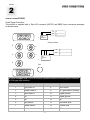
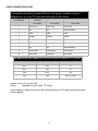
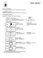
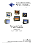
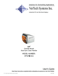
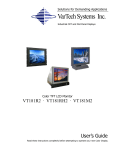
Solutions for Demanding Applications
VarTech Systems Inc.
Industrial CRT and Flat Panel Displays
VT14A-C1
Console Mount
Auto Sync Color Monitor
User’s Guide
Read these instructions completely before attempting to operate your new Color Display.
TABLE OF CONTENTS
Sections
Page
1
Warning and Caution
2
Video Connections
2-3
5BNC Connectors
4
Controls
5
Mode Operations
6
4
Chassis Mount Mechanical
7
5
Specifications
8
3
1
Section
1
SAFETY WARNINGS
The following warnings and cautions are for your safety, for the prevention of injury from electric
shock and for the safe operation of the monitor. Please read them carefully.
♦
♦
♦
♦
♦
♦
♦
Do not block the ventilation slots or insert any objects into the monitor through them.
Do not spill water onto the monitor or spray aerosol cleaners directly onto its surfaces when
cleaning.
Always position and operate the monitor on a stable and safe surface.
Do not install the monitor in a damp area, or where it may be exposed to rain or other sources of
water.
Ensure that all accessible cables cannot be walked on, tripped over or damaged by furniture or
other transportable objects.
If the monitor is damaged or fails to function correctly, disconnect it from the AC source. Do not
attempt to repair it yourself. Consult a qualified service technician.
Serious electrical shock hazards exist within the covers of the monitor. Under no circumstances
should these covers be removed.
WARNING
Changes or modifications to this unit not expressly approved by the party
responsible for compliance could void the user's authority to operate the equipment.
NOTE
This equipment has been tested and found to comply with the limits for a class B digital device,
pursuant to part 15 of the FCC rules. These limits are designed to provide reasonable protection
against harmful interference in a residential installation. This equipment generates, uses and can
radiate radio frequency energy and, if not installed and used in accordance with the instructions,
may cause harmful interference to radio communications. However, there is no guarantee that
interference will not occur in a particular installation. If this equipment does cause harmful
interference to radio or television reception, which can be determined by turning the equipment off
and on, the user is encouraged to try to correct the interference using one or more of the following
measures:
- Reorient or relocate the receiving antenna;
- Increase the separation between the equipment and the receiver;
- Connect the equipment into an outlet on a circuit different from that to
which the receiver is needed;
- Consult the dealer or an experienced radio/TV technician for help.
-1-
Section
2
VIDEO CONNECTIONS
VIDEO CONNECTIONS
Video Signal Correction
The monitor is supplied with a 15pin HD connector (HD15F) and 5BNC input connectors arranged
as shown below:
ON
OFF
1
1
9
DIP
SWITCH A
*
*
*Factory Default
R
H
ON
OFF
V
G
1
DIP
SWITCH
B
*
*
B
DDC
1
15
15 Pin D CONNECTOR: This is an industry standard connector providing easy connection
to VGA type video sources.
PIN
FUNCTION
PIN
FUNCTION
1
Red Video In
8
Blue Return
2
Green Video In
9
NC (grounded in monitor)
3
Blue Video In
10
Digital ground
4
NC
11
Digital ground
5
NC
12
NC
6
Red Return
13
Horizontal sync
7
Green Return
14
Vertical sync
15
NC
-2-
VIDEO CONNECTIONS CONT.
9 Pin D CONNECTOR: This connector allows the monitor to work with TTL video signals.
It is compatible with industry standard EGA and CGA signals. In addition it can be
configured for 3, 4 or 6 bit TTL video from other types of video source.
Pin Number
Function
3 bit video
4 bit video
6 bit video
1
GND (ov)
GND (ov)
GND (ov)
2
NC
NC
Red Intensity
3
Red
Red
Red
4
Green
Green
Green
5
Blue
Blue
Blue
6
NC
Intensity
Green Intensity
7
NC
NC
Blue Intensity
8
Horiz sync
Horiz sync
Horiz sync
9
Vert sync
Vert sync
Vert sync
DIP SWITCH (A) SETTINGS: SW1 and SW2 control the number of TTL colors.
SW1
SW2
Colors
OFF
OFF
8
OFF
ON
16
ON
OFF
64
ON
ON
AUTO 16/64
Video Levels: 0.7v p-p into 75Ω
Syncs:
Separate H and V syncs TTL levels
In the majority of cases the monitor will connect directly to a PC type computer using the
cable supplied.
-3-
5BNC CONNECTORS
These connectors allow the monitor to work with Red, Green and Blue coaxial cable. The monitor
synchronization may be Sync on Green, Composite sync or Separate Horizontal and Vertical sync.
The “H” input is used for composite sync.
Video inputs:
Red, Green, Blue. 0.7v p-p into 75 Ω
Sync inputs:
1. Sync on green 0.3v p-p into 75Ω superimposed onto green video. (3 wire)
2. Composite sync TTL level, positive or negative, combined horizontal or vertical sync. (4 wire)
3. Separate syncs TTL level, positive or negative, separate horizontal and vertical sync. (5 wire)
DIP SWITCH (B) SETTINGS
SW1,2,3 75Ω / Hi Z. The input impedance of the Red, Green, Blue BNC inputs can be switched
between 75Ω and High impedance. For normal operation the switches should be in the ON position
(75Ω). If it is required to connect more than one monitor to a single video source (loop through) then
the switches may be switched to OFF so that the combined input impedance of more than one
monitor remains at 75Ω. These three switches have no effect on the 15 way D input connector.
-4-
Section
3
DIGITAL CONTROLS
DIGITAL CONTROLS
The digital controls are located on the rear side of the monitor.
Normal Mode Controls
Operates the functions when the LED power is on continuously.
Function Mode Controls
Operates the functions when the LED is flashing.
LED
Function Key
Press to switch between
normal mode (LED will stop flashing) and
function mode (LED will start flashing).
VT
Switch
Contrast
Press “-” to decrease
Press “+” to increase
Function
Program Store*
Press to save picture alignment.
(Also returns monitor to normal
mode)
Brightness
Press “-” to decrease
Press “+” to increase
Vertical Size
Press “-” to decrease size
Press “+” to increase size
Pincushion*
Press to adjust curvature of
picture sides
Horizontal Size
Press “-” to decrease size
Press “+” to increase size
Vertical Position
Press “-” to move picture down
Press “+” to move picture up
Horizontal Position
Press “-” to move picture left
Press “+” to move picture right
∗
Press Function button.LED will blink allowing for keystone,
store program and pincushion adjustments.
-5-
Keystone*
Press “-” or “+” to make sides of
picture parallel
MODE OPERATIONS
In the normal mode of operation, the LED is not flashing.
Disable Keypad
1. Press and release the FUNCTION (upper right) switch. The LED will now be flashing.
2. Simultaneously press the FUNCTION and the VT (upper left) switches. Note that the VT switch is
not labeled. The LED will momentarily be off and then resume flashing.
3. Press and release the FUNCTION (upper right) switch. The LED will not be flashing.
4. To enable the keypad, repeat the above steps.
Factory Default Settings
1. Press and release the FUNCTION (upper right) switch. The LED will now be flashing.
2. Simultaneously press the VT switch and the VERTICAL SIZE + (bottom right) switches. The LED
will momentarily be off and then resume flashing. All stored setups will be deleted except original
factory setups.
3. Press and release the FUNCTION (upper right) switch. The LED will not be flashing.
Display Storage
1. Adjust the display for Brightness, Contrast, Horizontal Position, Horizontal Size, Vertical Position,
Vertical Size. This is done while the LED is not flashing.
2. Press and release the FUNCTION (upper right) switch. The LED will now be flashing.
3. Adjust the display for Keystone and Pincushion.
4. Press the CONTRAST + switch. This will store the display and return the keypad to normal
operation. The LED will not be flashing.
Horizontal frequency bands
Band
Frequency Range
Band
Frequency Range
1
<14.96kHz
9
33.42 - 36.28kHz
2
14.96 - 16.87kHz
10
36.82kHz—40.74kHz
3
16.87 - 19.10kHz
11
40.74 - 46.79kHz
4
19.10 - 22.60kHz
12
46.79 - 49.02kHz
5
22.60 - 24.83kHz
13
49.02 - 52.52kHz
6
24.83 - 27.69kHz
14
52.52 - 57.29kHz
7
27.69 - 29.28kHz
15
57.29 - 60.16kHz
8
29.28 - 33.42kHz
16
>60.16kHz
Vertical frequency bands
Band
Frequency Range
1
<56Hz
2
56 - 65Hz
3
65 - 78Hz
4
>78hz
-6-
Section
5
SPECIFICATIONS
ENGINEERING SPECIFICATIONS
Size
14”
Pitch
.28mm
Deflection Angle
90º
Phosphor
Medium Short B22
Resolution Capabilities
CGA to SVGA
Active Display Area
11.25” x 8.25” / 285.75mm x 209.55mm
Power Source
90 - 265 volts AC autoranging
50/60 Hz, 1.5 amps ac
Power Consumption
90 Watts
Horizontal Frequency
15kHz to 40kHz
Vertical Frequency
40Hz to 100Hz
Bandwidth
65MHz
Video Input Connector
HD15(F) and 5BNC, Optional DB9
Video Input Signal
Analog 0.7 p-p / 75Ω or TTL 3, 4 or 6 bits
Sync
Separate or Composite Sync:TTL pos. or neg.
Sync:TTL pos. or neg.
Sync on Green (SOG)
0.3V p-p, negative
Temperature
Operating: 0 to 50ºC
Storage: -20 t0 60ºC
Humidity
Operating: 20 to 80% NC
Storage: 10 to 90% NC
Degaussing
Automatic at power ON & Manual
Note: For continued compliance with Electromagnetic Compatibility limits, this monitor
must be used with the signal lead supplied.
-8-
VARTECH SYSTEMS INC.
HEADQUARTERS
11529 Sun Belt Ct.
Baton Rouge, Louisiana 70809
Toll-Free: 800.223.8050
International Phone: 001.225.298.0300
Fax: 225.297.2440
E-mail: [email protected]
www.vartechsystems.com
150-048-002
5.23.03