1
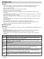
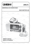
UM415
SUBMERSIBLE DSC MARINE RADIO
RADIO MARITIME ASN
OWNER’S MANUAL
GUIDE D’UTILISATION
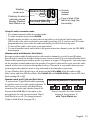
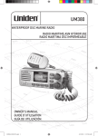
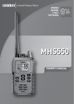
Making a Distress Call
Lift the red cover. Press and hold the DISTRESS button for three seconds.
Your radio transmits your boat’s location every few minutes until you
receive a response.
##NOTE: If the radio displays Enter User MMSI, cancel the automatic distress
call and make a normal voice distress call.
Making a Voice Distress Call
Lift the red cover
and press the
DISTRESS button.
Speak slowly - clearly - calmly.
For future reference, write your boat’s name & call sign here:
1. Make sure your radio is on.
2. On the microphone, press the 16/9-TRI button to switch to Channel 16 (156.8 MHz). (If the
corner of the display does not show 16, press the 16/9-TRI button again until it does.)
3. Press the PUSH TO TALK button on the microphone and say: “MAYDAY -- MAYDAY -MAYDAY.”
4. Say “THIS IS {name of your boat (three times) and call sign/boat registration number
(once).”
5. Repeat “MAYDAY {name of your boat}” once.
6. Tell where you are: (what navigational aids or landmarks are near, or read the latitude
and longitude from your GPS).
7. State the nature of your distress (e.g. are you sinking, medical emergency, man
overboard, on fire, adrift, etc. ).
8. State the type of assistance you need (medical, towing, pumps, etc.).
9. Give number of persons aboard and conditions of any injured persons.
10.Estimate present seaworthiness of your ship (e.g. how immediate is the danger due to
flooding or fire or proximity to shore).
11.Briefly describe your ship, giving ship name (e.g. “Blue Duck is 32 foot cabin cruiser,
white hull, blue deck house”).
12.Say: “I WILL BE LISTENING ON CHANNEL 16.”
13.End message by saying “THIS IS {name or call sign of your boat}, OVER.”
14.Release the PUSH TO TALK button and listen.
If you do not get an answer after 30 seconds, repeat your call, beginning at step 3, above.
2
English
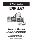
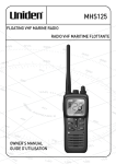
Faire un appel de détresse
Soulevez le couvercle rouge. Maintenez la touche DISTRESS enfoncée
pendant trois secondes.
Le UM415 transmet la position de votre bateau à intervalles réguliers de
quelques minutes, jusqu’à ce que vous receviez une réponse.
##REMARQUE : Si la radio affiche Enter User MMSI (Entrer l’ISMM de
l’utilisateur), annulez l’appel de détresse automatique et faites un
appel de détresse couvercle rouge etvocal standard.
Soulevez le
couvercle rouge
et appuyez sur la
touche DISTRESS.
Faire un appel de détresse vocal
Parlez lentement – clairement – calmement.
Pour toute référence ultérieure, transcrivez ci-dessous le nom et l’indicatif d’appel de votre
bateau :
1. Vérifiez si votre radio est en marche.
2. Appuyez sur la touche 16/9-TRI du microphone afin de commuter au canal 16 (156,8
MHz). (Si le canal 16 n’apparaît pas à l’affichage, appuyez de nouveau sur la touche 16/9TRI jusqu’à ce qu’il soit affiché.)
3. Appuyez sur le bouton de microphone PUSH TO TALK et dites :“MAYDAY - MAYDAY
– MAYDAY”.
4. Donnez l’identité de votre navire en disant : “ICI {nom de votre bateau (trois fois) ou
indicatif d’appel et le numéro d’identification de votre bateau (une fois)}”.
5. Dites “MAYDAY {nom ou indicatif d’appel de votre bateau} une fois”.
6. Donnez votre position : (quels sont les points de repère ou aides à la navigation près
de vous ou lisez les coordonnées de longitude et de latitude apparaissant sur votre
dispositif GPS).
7. Révélez la nature de votre détresse (par exemple, nous sommes en train de couler,
urgence médicale, un homme à la mer, un incendie, nous sommes à la dérive, etc.
8. Révélez la nature de l’assistance désirée (médicale, remorquage, essence, etc.)
9. Donnez le nombre de personnes à bord et les conditions des blessés, s’il y en a.
10.Donnez la condition de navigabilité actuelle de votre navire, tel que le degré de l’urgence
par rapport à l’inondation, à l’incendie ou à votre proximité de la côte.
11.Donnez une brève description de votre navire en donnant le nom du bateau (par exemple,
“Blue Duck est un yacht de croisière de 32 pieds, avec une coque blanche et un rouffle
bleu.).
12.Dites : “JE VAIS ÉCOUTER SUR LE CANAL 16”.
13.Terminez le message en disant “ICI {nom ou indicatif d’appel de votre bateau}, À VOUS”.
14.Relâchez le bouton PUSH TO TALK du microphone et écoutez.
Si vous n’obtenez pas de réponse après 30 secondes, répétez l’appel encommençant à l’étape
3 ci-dessus.
English 3
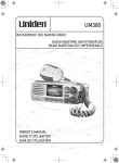
Cómo hacer una llamada de apuro
Levante la tapa roja. Mantenga oprimido el botón DISTRESS por tres
secundos. La radio UM415 transmitirá la localidad de su navío cada
cuantos minutos hasta que reciba una respuesta.
##Nota: Si la radio exhibe (Inserte el MMSI del usuario), cancele
la llamada de apuro automática y haga una llamada de apuro
normal por voz.
Cómo hacer una llamada de apuro por voz
Levante la tapa
roja y oprima el
botón DISTRESS.
Hable despacio -- claro -- y con calma.
Para acordarse en el futuro, escriba el nombre y la señal de su navío aquí:
1. Asegúrese de que la radio está encendida.
2. En el micrófono, oprima el botón 16/9-TRI para cambiar al canal 16 (156.8 MHz). (Si la
esquina de la pantalla no muestra 16, oprima el botón 16/9-TRI otra vez hasta que lo haga.)
3. Oprima el botón PUSH TO TALK (Oprima para hablar) en el micrófono y diga: “MAYDAY
--- MAYDAY--- MAYDAY.”
4. Diga “ESTE ES {nombre o señal de su navío}.”
5. Diga “MAYDAY {nombre o señal de su navío}.”
6. Describa donde se encuentra: (ayudas de navegación o marcas destacadas cercanas, o lea
la latitud y la longitud en su GPS).
7. Describa la clase de su apuro, ej., se está hundiendo, emergencia médica, hombre al agua,
hay fuego, está a la deriva, etc.
8. Describa la cantidad de personas abordo y las condiciones de cualquier persona
lesionada.
9. Estime la navegabilidad actual de su navío, ej., cuanto de inmediato es el peligro de
inundación o de incendio o proximidad a la costa.
10.Describa brevemente su navío (largura, tipo, color, casco).
11.Diga: “ESTARÉ ESCUCHANDO EN EL CANAL 16.”
12.Termine el mensaje diciendo: “ESTE ES {nombre o señal de su navío}, OVER.”
13.Suelte el botón PUSH TO TALK y escuche. Si no recibe una contestación dentro de 30
segundos, repita su llamada, comenzando con el paso 3, descrito arriba.
Si no recibe una contestacion dentro de 30 segundos, repita su llamada, comenzando con el
paso 3, descrito arriba.
Visite www.uniden.com para bajar el manual en español de la radio UM415.
4
English
Contents
Making a Voice Distress Call....................... 2
Faire un appel de détresse vocal ............... 3
Cómo hacer una llamada de apuro
por voz ..................................................... 4
Introduction .............................................. 6
Features ..................................................... 6
Manual overview ....................................... 6
Getting Started .......................................... 7
What’s included ......................................... 7
Parts of the Radio . .................................... 8
Parts of the Microphone............................. 9
Turning on the Radio................................ 10
Setting the UIC Channel Mode
(USA/CAN/INT)....................................... 10
How It Works .......................................... 10
Normal mode operation .......................... 11
Scan mode . .............................................. 13
Weather mode ......................................... 14
Using Your Radio...................................... 16
Using Your Radio ...................................... 16
Making a voice MAYDAY call . .................. 17
Setting the volume ................................... 17
Setting the squelch level .......................... 17
Changing the channel............................... 17
Making a transmission.............................. 17
Boosting the transmission power............. 18
Choosing Triple Watch or Dual Watch...... 18
Using FIPS codes for weather alerts......... 19
Changing display and sound options ....... 20
Setting the GPS position manually ........... 20
Using Digital Selective Calling (DSC)
Features ................................................ 21
What is DSC? ............................................ 21
Advanced DSC features ............................ 21
What is an MMSI number?....................... 21
Entering MMSI numbers .......................... 22
Using the Directory................................... 23
Making DSC Calls....................................... 24
Making an automatic distress call............. 26
Receiving a DSC call.................................. 27
Test Calls................................................... 28
Position Request and Reply...................... 29
Putting the radio into standby ................. 31
Disabling automatic channel switching..... 31
Renaming Channels . ................................ 32
Installing the Hardware ........................... 32
Mounting the radio .................................. 32
Connecting the radio................................ 33
Connecting to a GPS receiver . ................. 34
Connecting to a Chartplotter.................... 36
Connecting to an External Speaker........... 37
Maintenance and Troubleshooting........... 37
Engine Noise Suppression......................... 39
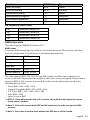
Specifications........................................... 39
Radio Specifications ................................. 39
Reference Tables ..................................... 40
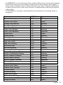
Channel descriptions and
what they mean...................................... 40
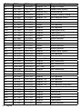
US Marine Channels and Frequencies...... 41
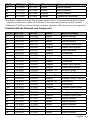
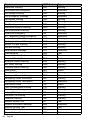
Canadian Marine Channels and
Frequencies............................................ 43
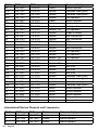
International Marine Channels and
Frequencies............................................ 44
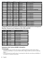
Weather Channels and Frequencies
(US, CAN, and INT).................................. 46
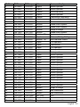
Emergency Alert System (SAME)
Information............................................. 46
No Response Event Code.......................... 49
NMEA Operation....................................... 49
NMEA Output . ......................................... 50
Regulations and Safety Warnings ............ 50
Three Year Limited Warranty . ................. 51
Introduction
Features
xx Submersible Design - Complies with JIS8 water-resistant standards, which means the
xx
xx
xx
xx
xx
xx
xx
xx
xx
radio can be submerged in 1.5 meter of water for 30 minutes without damage.
Large, dot matrix display
Advanced DSC Class D functions, including Test Calling
Channel select buttons on the microphone
Memory scan mode - Lets you save channels to memory and monitor them in quick
succession.
Transmitter Power Level Select - Lets you boost the transmitter power from 1 watt to 25
watts for added transmission distance.
Battery level display and tone - Sounds an alert tone if the battery voltage goes too high
or too low.
Triple Watch Operation - Checks the Coast Guard Distress/Hailing channels 16 and 9 in
the background.
All marine VHF channels for the U.S., Canada, and international waters
National Oceanic and Atmospheric Administration (NOAA) weather channel watch Sounds a warning tone when a hazard alert is issued for your area.
Manual overview
Conventions
This manual uses several different type styles to help you distinguish between different parts
of the radio:
xx BOLD SMALL CAPITALS indicates an actual button or knob on the radio or microphone.
xx Upper and Lower Case bold indicates a connector or label on the radio.
xx Italics indicate text on the display, such as menu options, prompts, and confirmation
messages.
6
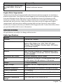
Term
Meaning
DSC
Digital Selective Calling. A VHF radio standard for communicating among
boats and sending automated distress calls.
FIPS
Federal Information Processing Standard. A set of location codes roughly
equivalent to your county codes.
WX
Weather Radio
GPS
Global Positioning System
NMEA
National Marine Electronics Association. The organization that governs
standards for electronic equipment used on boats. NMEA 0183 is the
standard for serial data communication used by GPS.
MMSI
Maritime Mobile Service Identity number. A unique, nine-digit number that
identifies you and your boat when making DSC calls. It is also used by the
Coast Guard if you send an automated distress call.
Station
Any DSC radio, whether it’s operated on a boat, at a marina, or by a shore
station.
English
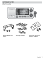
Getting Started
What’s included
Mounting Bracket and
Knobs
Mounting Hardware
Microphone Hanger and
Mounting Hardware
English
7
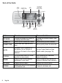
Parts of the Radio
ENT1W/25W
button
CHANNEL UP &
CHANNEL DOWN
button
LCD
display
VOLUME-PWR
(power) knob
(turn clockwise to
increase volume)
Microphone
cord
SQUELCH knob
CLR-SCAN
CALL(turn clockwise to
(channel
MENU
decrease channel
scan) button
DISTRESS button
noise)
button
16/9-TRI
WX-MEM
(triple/dualbutton
watch) button
8
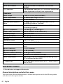
Button
Press to...
Press and hold to...
ENT-1W/25W
Choose an option on a menu or
to display the GPS data.
Change the transmit power (see
page 18).
Channel Up
Move up one channel at a time.
Move quickly up the channels.
Channel Down
Move down one channet at a
time.
Move quickly down the channels.
16/9-TRI
1st press: Go to Channel 16.
2nd press: Go to Channel 9.
Go into Triple Watch or Dual
3rd press: Go back to the original Watch mode (see page 18).
channel.
CLR-SCAN
Go to previous menu or cursor
position in menu mode.
Start scanning the channels
saved in memory.
WX-MEM
Listen to the current weather
conditions in your area.
Save a channel into memory or
remove a channel from memory.
CALL-MENU
Display the call menu.
Display the normal menu.
DISTRESS
Select the nature of your distress
for a distress call.
Transmit a distress call.
English
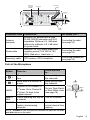
Antenna
connector
(SO238)
Accessory
cable
Heat sink
Red wire
(+)
ANTENNA
13.8V DC
Black wire
(-)
Power
Cable
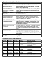
Connector/Cable Connects to...
For details, see ...
Antenna
connector
External VHF antenna with a male
PL259 (SO238) connector and 50 Ω
impedance. Minimum 4 ft, 3dB rated
antenna for sailboats, 8 ft, 6 dB rated
for power boats.
Connecting the radio
(see page 33).
Power cable
Nominal 13.8 VDC power supply with
negative ground (10.5 VDC to 16.0
VDC) (Red wire +, black wire -). Connecting the radio
(see page 33).
Accessory cable
GPS receiver, GPS chartplotter.
Connecting accessories
(see page 34).
Parts of the Microphone
Button
Press to...
Press and hold
to...
(
)
Move up one channel at a
time.
Move quickly up
the channels.
(
)
Move down one channel at
a time.
Move quickly down
the channels.
16/9-TRI
1st press: Go to Channel 16.
2nd press: Go to Channel 9.
3rd press: Go back to the
original channel.
Go into Triple Watch
or Dual Watch mode
(see page 18).
Push-to
Talk
Cancel scanning and stay on Talk on a channel.
a channel.
SCAN/MEM
Activate the channel scan
feature; start scanning
channels.
UP button
(move up a
channel)
Push-to-Talk
button
16/9 TRI
(Triple/DualWatch) button
SCAN/MEM
button
DOWN button
(move down
a channel)
Save/delete the
current channel from
memory.
NOTE: SCAN/MEM on the microphone functions the same as the SCAN
and MEM buttons on the radio.
English
9
Turning on the Radio
Turn the VOLUME-PWR knob clockwise to turn on the radio. As it powers on, the radio displays
the user MMSI number; if there is no MMSI set, the radio displays MMSI not entered.
When it powers on, the radio selects the last channel used.
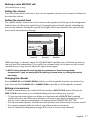
Setting the UIC Channel Mode (USA/CAN/INT)
The radio comes preset to use the UIC channels assigned for the United States. If you are
operating in an area that uses Canadian or international UIC channels, you will need to
change the channel mode.
Press and hold -
Setup
USA/CAN/INT
UIC Channels
USA Mode
Canada Mode
Intl Mode
Back[CLR]
16
Select[ENT]
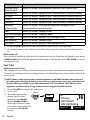
1. Press and hold CALL-MENU to display the normal menu, and choose the Setup sub-menu.
2. Select USA/CAN/INT. The screen displays the UIC channel setup.
3. Choose the channel mode you want to use: US (USA Mode), Canadian (Canada Mode), or
international (Intl Mode).
4. Press ENT-1W/25W. The radio activates the new channel mode and exits the menu.
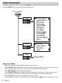
How It Works
Your radio has three basic modes of operation:
Mode
What It Does
Use It When
To Turn it on./off...
Normal
Monitors a single
marine radio channel
and lets you talk on
that channel.
You want to talk to
another station on a
specific channel.
(default mode)
Scan
Monitors all the channels you save into
memory.
You have a small group
of channels you use
most often and want to
check them for traffic.
Weather
Monitors the selected
NOAA weather
channel.
You want to hear the
current and forecasted
weather in your area.
Press and hold the
CLR-SCAN button.
Press the WX-MEM
button.
In addition to the three basic operation modes, your radio also provides three different
“watch” modes which you can activate during any of the three basic modes. In these watch
10 English
modes, the radio briefly checks for activity on a specific channel then returns to its previous
mode.
Watch Mode What It Does
Use It When
To Turn it on./off...
Weather
Alert
Checks for alerts
on the last weather
channel you
used every seven
seconds.
You want to be
made aware of
severe weather
conditions in your
area.
conditions in your area. Select WX Alert Mode in
Setup submenu, and then
choose ON or OFF.
Triple
Checks for activity on You want to monitor Press and hold 16/9-TRI for
channels 16 and 9
a channel yet
two seconds.
every two seconds.
maintain a watch on
channels 16 and 9.
Dual
Checks for activity on You want to monitor
channel 16 every two a channel yet
seconds.
maintain a watch on
channel 16.
Change Triple Watch
to Dual Watch in the
setup menu, then press
and hold 16/9-TRI for two
seconds.
##NOTE: You are required to monitor channel 16 whenever your boat is underway. You should
have either Triple Watch or Dual Watch on at all times.
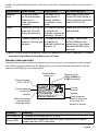
Normal mode operation
Normal mode monitors whatever channel you select, and you can transmit on that channel
also. While using normal mode, the display lets you see the following information (not all
indicators will display at the same time):
Weather Alert
Watch on
Transmit power
(1 W or 25 W)
Current channel
is stored in
memory
Status messages
(see the status
message table)
25
25 Watts USA
Memory Alert
GPS Data OK
Marine Operator
Channel mode
(USA, CANadian,
or INTernational)
Current
channel
number
Current channel
name (if the name
is too long, the
name line scrolls)
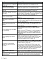
Message
Meaning
GPS Data OK
The radio is receiving valid GPS data.
Check GPS
The radio is not receiving valid GPS data: check the GPS status
screen and the GPS connection.
English 11
Message
Meaning
Input Position
The radio has been unable to receive valid GPS data for at least four
hours; it can no longer track your position. You need to manually input
your position (see Setting the GPS position manually on page 20).
Battery Low
The battery voltage output is too low (below 10.5 VDC).
Battery High
The battery voltage output is too high (above 16.0 VDC).
Using the radio in normal mode
xx To transmit, press and hold PUSH TO TALK on the microphone. Release the button when
you are finished talking.
xx For the best sound quality, hold the microphone about two inches from your mouth while
you’re talking.
xx Press CHANNEL UP on the radio or the microphone to move up one channel at a time. Press
and hold either button to scroll quickly up the channels.
xx Press CHANNEL DOWN on the radio or the microphone to move down one channel at a time.
Press and hold either button to scroll quickly down the channels.
xx To change the transmit power, press and hold the ENT-1W/25W for two seconds. The
transmit power switches between 1 watt and 25 watts each time you press and hold ENT1W/25W.
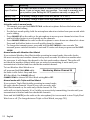
Normal mode with Weather Alert Watch
If you activate Weather Alert Watch while operating in normal mode, the radio checks
the most recently-used weather channel every seven seconds. If it detects a weather alert
for your area, it will change the channel to the last-used weather channel. The radio will
not check the weather channel while you are actively transmitting; it waits until your
transmission is finished and then checks the weather channel.
To turn Weather Alert Watch on or
off, press and hold CALL-MENU while
the radio is idle. Select Setup and then
WX Alert Mode. Use CHANNEL UP and
CHANNEL DOWN to choose WX Alert Mode setting ON or Off.
Normal mode with Triple and Dual Watch
If you activate Triple Watch while operating in normal mode,
the radio checks channels 16 and 9 every two seconds; with
Dual Watch turned on, the radio only checks channel 16. The
radio will not check channels 16 or 9 while you are actively transmitting; it waits until your
transmission is finished and then checks the channels.
Press and hold 16/9-TRI (on the radio or the microphone) for two seconds to turn Triple/Dual
Watch on or off. (To change between Triple or Dual Watch, see page 18.)
12 English
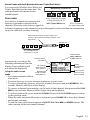
Normal mode with both Weather Alert and Triple/Dual Watch
You can activate Weather Alert Watch and
Monitoring Channel 25
Triple/ Dual Watch at the same time. The
radio performs both checks at their
scheduled time.
09 16
09 16
09 16
Scan mode
Every 2 seconds, the radio
wx
checks channels 9 & 16.
You can save channels into memory and
with
Triple
Watch
on
Every
7
seconds,
then use scan mode to monitor those
the
radio
checks
the
channels. When the radio detects a signal on
most recently-used
a channel, it pauses on that channel as long as the signal is received; when the
transmission
weather
channel.
stops, the radio will continue scanning.
with WX Alert on
When it detects a signal, the radio stays on the
channel until you press the CHANNEL UP button or the
signal stops.
Resume scan
08
10
11
12
13
14
15
17
20
The radio scans about
5 channels in 1 second.
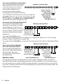
In scan mode, you can get the
following information from the
display (some indicators will
not always be displayed).
Transmit power
last used
All scanned
channels must
be in memory
Channel mode
(USA, CANadian,
or INTernational)
07
1 Watt
USA
Memory
Scanning Channels
01A,03A,05A,06,07A,08
Current
channel being
scanned
Scan list (if the
Normal scan
Using the radio in scan
text is too long,
mode or Triple/
the line scrolls)
mode Dual-watch on
xx You cannot transmit while in
scan mode. xx You must have two or more channels in memory to start a scan.
xx To save a channel into memory, select the channel, then press and hold WX-MEM for two
seconds. Memory will show on the display.
xx To remove a channel from memory, set the radio to that channel, then press and hold WXMEM for two seconds. Memory will no longer show on the display.
xx To activate scan mode, press and hold CLR-SCAN. Press and hold CLR-SCAN again to return
to the previous mode.
xx When the radio automatically stops on a channel, press CHANNEL UP to leave that channel
and resume scanning.
xx To end the scan, press the microphone’s PUSH TO TALK, CALL-MEM, or WX-MEM buttons. The
radio remains on the last scanned channel.
English 13
Scan mode with Weather Alert Watch
If you activate Weather Alert Watch
while operating in scan mode, the
radio checks the most recentlyused weather channel every
seven seconds, then continues
scanning the next channel in memory.
To turn Weather Alert Watch on or off, press and hold
CALL-MENU while the radio is idle. Select Setup and then
WX Alert Mode. Use CHANNEL UP and CHANNEL DOWN to
choose WX Alert Mode setting ON or Off.
Scan mode with Triple and Dual Watch
If you activate Triple Watch while
Memory Channel Scan
operating in scan mode, the radio
08 10 11 12 13 14 15 17 20 24 25
checks channels 16 and 9 every
two seconds, then goes on to scan Every 2 seconds,
the next channel; with Dual Watch the radio checks
turned on, the radio only checks
channels 9 & 16
then goes on to
channel 16.
the next channel. 09 16
Press and hold 16/9-TRI (on the
radio or the microphone) for two seconds
turn Triple/Dual
withtoTriple
Watch on Watch on or off. (To change
between Triple or Dual Watch, see page 18.) Reversed 16 & 9
20061215
#17
Press and hold the CLR-SCAN key to turn offUJ-SW
Scan mode
and set
the radio to Triple/Dual Watch
mode.
Scan mode with both Weather
Alert and Triple/Dual Watch
You can activate Weather Alert
Watch and Triple/Dual Watch at
the same time. The radio
performs both checks at their
scheduled time.
Weather mode
Memory Channel Scan
08
10
11
Every 2 seconds,
the radio checks
channels 9 & 16
then goes on to
the next channel.
12
13
09 16
14
15
17
20
Every 7 seconds,
the radio checks
the last-used
weather channel,
then scans the
next channel.
24
25
wx
with Triple Watch on
with WX Alert on
Reversed
16
&
9
In cooperation with the FCC, NOAA also uses the weather channels to alert you of other
20061215
#17
hazards besides weather (child abduction UJ-SW
alerts, nuclear,
biological,
etc.). In weather mode,
the radio monitors one of the ten NOAA weather channels. If any type of alert is received for
your area, the radio sounds an alert tone and displays the type of alert. In weather mode, the
display shows the following:
14 English
Weather
mode is on
Flashing: An alert
has been issued
Steady: Weather
Alert Watch is on
Weather Band
Alert
09
Hurricane Warning
Current
channel
number
Type of alert (if the
text is too long, the
line scrolls)
Using the radio in weather mode
xx You cannot transmit while in weather mode.
xx To enter weather mode, press WX-MEM.
xx Weather mode can filter out alerts that do not affect your location if the location code
(FIPS code) of the alert is entered in your radio (see page 19). If you have no FIPS codes
programmed into your radio, the radio will notify you of all alerts in any area.
xx To turn off the radio’s alert tone, press any button.
xx To cancel weather mode and return to the previous marine channel, press the WX-MEM
button again.
Weather mode with Weather Alert Watch
Because weather mode already monitors the weather channels, you don’t need Weather
Alert Watch to check the weather channel every seven seconds. If you activate Weather Alert
Watch while operating in weather mode, it operates as a type of “sleep mode”: the radio stays
on the weather channel and mutes the speaker. If an alert is detected for your area, the radio
sounds an alert tone and turns the speaker back on. This mode is very useful when you are
anchoring for the night but want to stay informed of any hazards in your area.
To turn Weather Alert Watch on or off, press and hold CALL-MENU while the radio is idle.
Select Setup and then WX Alert Mode. Use CHANNEL UP and CHANNEL DOWN to choose WX Alert
Mode setting ON or Off.
Weather mode with Triple and Dual Watch
If you activate Triple Watch while operating
in weather mode, the radio checks channels 16
and 9 every two seconds; with Dual Watch
turned on, the radio only checks channel 16.
Press and hold 16/9-TRI (on the radio or the
microphone) for two seconds to turn Triple/
Dual Watch on or off. (To change between
Triple or Dual Watch, see page 18.)
Monitoring Weather Channel WX08
09 16
09 16
09 16
Every 2 seconds, the radio checks
channel 9, then channel 16
with Triple Watch on
English 15
Using Your Radio
To display the radio call menu, press CALL-MENU. To display the radio normal menu, press and
hold CALL-MENU. The menu has the following options:
Press and hold -
Setup
System
USA/CAN/INT
Dual/TriWatch
GPS Setup
FIPS Codes
Auto CH SW
POS Reply
Test Reply
Channel Name
Group MMSI
User MMSI
WX Alert Mode
[Exit]
Contrast
Lamp Adjust
Key Beep
[Exit]
[Exit]
(Close Menu)
Using Your Radio
xx An arrow on the left side indicates the current selection.
xx Press CHANNEL UP on the radio or the microphone to move up a line in the menu; if you are
at the top line in the menu, the cursor jumps to the bottom of the menu.
xx Press ENT-1W/25W to choose the selected item.
xx Press CHANNEL DOWN on the radio or the microphone to move down a line in the menu; if
you are at the bottom line of the menu, the cursor jumps to the top of the menu.
xx Press CLR-SCAN to go back to the previous menu screen.
xx From any menu screen, choose Exit or press and hold CALL-MENU to close the menu screen.
16 English
Making a voice MAYDAY call
(see inside front cover)
Setting the volume
Turn the volume knob clockwise to increase the speaker volume; turn it counter-clockwise to
decrease the volume.
Setting the squelch level
The squelch feature reduces the level of static on the speaker by filtering out the background
channel noise. At the lowest squelch level, the speaker plays all radio signals, including any
noise on the channel. Setting the squelch level higher filters out channel noise and lets only
actual radio transmissions through.
Strong signals
Weak signals
Noise
No
Squelch
Medium
Squelch
High
Squelch
While listening to a channel, adjust the SQUELCH knob until the noise is filtered out and you
can only hear the transmission. If you switch to a channel with a lot of noise or with a weak
transmission, you may need to adjust the squelch level again.
##NOTE: Setting the squelch level too high may prevent you from hearing weaker
transmissions. If you are having difficulty hearing a transmission, try setting the squelch
level lower.
Changing the channel
Press CHANNEL UP and CHANNEL DOWN briefly to scroll through the channels one channel at a
time. Press and hold CHANNEL UP or CHANNEL DOWN to quickly scroll through the channels.
Making a transmission
To make a transmission, press and hold the microphone PUSH TO TALK button. Release the
PUSH TO TALK button when you’re finished talking to let the other party respond.
xx To prevent stuck microphone problems or situations where PUSH TO TALK is pushed
accidentally, the radio limits your talk time to 5 minutes in a single transmission. If you
talk for over 5 minutes continuously, the display shows RELEASE MIC BUTTON.
xx For the best sound quality, hold the microphone about two inches away from your mouth.
xx You cannot transmit while the radio is in weather mode or scan mode.
xx See the channel lists beginning on page 40 for a list of receive-only channels.
English 17
Boosting the transmission power
In most situations, the 1 Watt transmission power is all you need. If you find yourself far
away from other stations and have trouble getting a response, you may need to boost the
transmission power from 1 Watt to 25 Watts:
1. Select the channel you want to transmit on.
2. Push and hold ENT-1W/25W for two seconds. The display shows 25 Watts in the upper left
hand corner.
3. The transmit power remains at 25 Watts until you change the setting back. Push and
hold ENT-1W/25W for two seconds. The display shows 1 Watt.
##NOTE: Don’t forget to change the transmission setting back to 1 Watt when you move closer
to other stations.
##NOTE: By default, when you change to channel 16, the radio automatically boosts the
power to 25 Watts. Be sure to change the power back to 1 Watt if you are not making an
emergency transmission.
Some channels (for example, channels 13 and 67) limit the power of transmission to 1 Watt
so that there is less interference between boaters attempting to use the channel at the same
time. If you switch to one of these channels, the radio changes back to 1 Watt automatically.
See the channel lists beginning on page 40 for a list of power-restricted channels.
Choosing Triple Watch or Dual Watch
In Triple Watch mode, the radio briefly checks channels 16 and 9 every two seconds. In Dual
Watch mode, the radio checks channel 16 only. Generally, Triple Watch is used in areas
where channel 9 is used as a hailing frequency while Dual Watch is used in areas where
channel 16 is used for distress and hailing. Your radio comes set to use Triple Watch; if you
want to use Dual Watch instead, you will have to select it in the setup:
Press and hold -
Setup
Dual/TriWatch
Dual/TriWatch
Dual Watch
Triple Watch
[Exit]
Back[CLR]
88
A
Select[ENT]
1. Press and hold CALL MENU to display the normal menu.
2. Select Setup and then Dual/Tri Watch.
3. Choose Dual Watch and press ENT-1W/25W. The radio activates the new setting and returns
to the Setup menu.
4. To reactive Triple Watch, repeat the procedure described above, but choose Triple
Watch in step 3.
18 English
Using FIPS codes for weather alerts
The US National Weather Service established 6-digit Federal Information Processing System
(FIPS) codes to issue weather alerts in specific areas. You can choose which areas you want
to hear alerts for by entering these FIPS codes in your radio. This can prevent you from being
bothered by events that are far from where you are boating. The radio only sounds the alert
tone if an incoming FIPS code matches one of the areas you selected.
xx For more information about how the NWS uses FIPS codes, see the NWS website: www.
nws.noaa.gov/nwr/nwsfipschg.htm.
xx To see an index of FIPS codes by state, see the website of the National Institute of
Standards and Technology (NIST): www.itl.nist. gov/fipspubs/co-codes/states.htm.
xx For information on the Canadian implementation of FIPS codes, called Canadian Location
Codes, see the website of the Meteorological Service of Canada (MSC): http://www.msc.
ec.gc.ca/msb/weatheradio/transmitter/index_e.cfm
##NOTE: If you travel outside the areas you have entered into your radio, you may not hear
alerts that affect your new location. Be sure to enter the FIPS codes of all the areas you plan
to travel to during this trip.
Follow the steps below to edit the list of FIPS codes. You can store up to 30 different FIPS
codes in your radio.
Press and hold -
Setup
Use the up and down arrows
to adjust each of the six
digits in turn.
FIPS Codes
FIPS Code
000000
16
[New]
Back[CLR] Forward[ENT]
1.
2.
3.
4.
5.
6.
7.
8.
9.
Display the normal menu and choose the Setup sub-menu.
Select FIPS Codes. The screen displays any previously-entered FIPS codes.
To add a new FIPS code, select New.
Use CHANNEL UP and CHANNEL DOWN to change the first of the six digits; CHANNEL UP
increases the number and CHANNEL DOWN decreases it.
When the first digit is correct, press ENT-1W/25W. The cursor moves to the next digit. Enter
the remaining five digits of the FIPS code in the same way. If you make a mistake while
entering a digit, press CLR-SCAN to erase the wrong number and moved the cursor to the
left digit.
When the sixth digit is correct, press ENT-1W/25W. The radio displays the new FIPS code
and asks you to confirm. To save this code, select Yes; to cancel this code, select No. The
radio returns to the list of FIPS codes.
To change an existing FIPS code, select the code you want to change.
To delete the FIPS code, select Delete. To edit the code, select Edit, then use CHANNEL UP
and CHANNEL DOWN buttons to change each of the six digits.
When you are satisfied with the list of FIPS codes, select Exit to close the menu screen.
English 19
Changing display and sound options
Contrast
Your radio display has 10 levels of contrast. To adjust the contrast, press and hold CALL-MENU
while the radio is idle. Select System and then Contrast. Use CHANNEL UP and CHANNEL DOWN to
change the contrast to your desired level.
To restore the default contrast setting, turn the radio off. Press CALL-MENU and hold it in while
you turn the radio on.
Lamp adjust
Your radio has 10 brightness levels on the display. To adjust the brightness, press and hold
CALL-MENU while the radio is idle. Select System and then Lamp Adjust. Use CHANNEL UP and
CHANNEL DOWN to change the brightness to your desired level.
Turning the key beep on and off
Key beep is the tone that sounds when you press a key or a button. To turn off the key beep,
press and hold CALL-MENU while the radio is idle. Select System and then Key Beep. Choose Off
to turn off the key beep.
Setting the GPS position manually
If the radio is not receiving valid GPS data, the radio displays Input Position. Follow the steps
below to manually input your position.
##NOTE: Be certain any manually-entered position is correct. If you enter the wrong position
and then make a DSC distress call, you will be telling the arrows to adjust each of the values
in turn.
Press and hold -
Setup
Use the up and down arrows
to adjust each of the values
in turn.
GPS Setup
Position Set
--/-- 11:22U
o
--.- KT
--o
35 40.610 N
o
139 46. 564 E
16
Back[CLR] Forward[ENT]
1. Display the normal menu and choose the Setup sub-menu.
2. Select GPS Setup and then choose Position Set.
3. The GPS manual input screen displays; the fields to be entered blink. The cursor
highlights the hour. Use CHANNEL UP and CHANNEL DOWN to set the displayed hours to
match coordinated universal time (UTC, also call Greenwich Mean Time and Zulu Time).
When the display matches UTC time, press ENT-1W/25W. If you make a mistake while
entering a digit, press CLR-SCAN to erase the wrong number and moved the cursor to the
left digit.
4. The cursor moves to highlight the minutes. Use CHANNEL UP and CHANNEL DOWN to adjust
the minutes and press ENT-1W/25W.
5. The cursor moves to highlight the degrees latitude. As you update each value, the cursor
moves to the next value in turn. At each number, use CHANNEL UP and CHANNEL DOWN to
adjust the number and press ENT-1W/25W.
When you have entered the last value, the radio returns to the GPS Setup menu.
20 English
Using Digital Selective Calling (DSC) Features
What is DSC?
Digital Selective Calling (DSC) is a standard that allows you to call other stations using their
unique identification code (the Maritime Mobile Service Identity or MMSI number), just
like you would call a phone number. To call another station, just enter that station’s MMSI
number and choose the voice channel you want to talk on. The radio uses channel 70 to
transmit your MMSI number to the other station along with the voice channel you requested.
If the other station accepts your call, both radios automatically switch to the requested voice
channel so you can talk to the other station.
DSC provides a system for automated distress calls. At the touch of a button, the radio can
transmit your MMSI number, the nature of your distress, and your current position based
on data from your GPS receiver. The radio repeats the distress call every few minutes until it
receives an acknowledgement.
The DSC standard dedicates a VHF channel—channel 70—to digital transmissions only. Since
digital transmissions require less bandwidth voice transmissions, channel 70 avoids the
problems of busy voice channels.
Advanced DSC features
Your radio supports the following DSC features:
Feature
Menu Item
Function
Individual Call
Individual
Contact another vessel from your directory.
Group Call
Group
Contact all vessels that share your group MMSI
code.
All Ships Call
All Ships
Broadcast to all vessels within range (used for
safety or advisory messages).
Position Request
POS Request
Request the current location of another vessel.
Position Send
Position Send
Transmit your current location to another
vessel.
Test Call
Test
Make sure your radio is working and configured
correctly/
Name and MMSI
Directory
Directory
Store a list of 20 names and MMSI identification
codes for DSC calls.
Standby Mode
Standby
Automaticcally respond to all DSC calls within
an “Unavailable” status.
Received Call Log
Receive Log
Display the last 10 distress calls received by the
radio and the last 20 general calls.
What is an MMSI number?
In order to use DSC features, you must be assigned an MMSI number and program that
number into your radio. There are two kinds of MMSI numbers: individual numbers for
use by single boats and group numbers for use by fleets, boating organizations, event
coordinators, etc.
English 21
You can get more information on MMSI numbers at these resources:
xx The dealer where you purchased the radio
xx Recreational boaters can obtain an MMSI number from the Boat Owner’s Association
of the U.S. (http://www.boatus.com/mmsi/ or call 800-536-1536) or Sea Tow Services
International (http://seatow. com/boating_safety/mmsi.asp)
xx Commercial boaters need a ship station license to get an MMSI number. For more
information, visit the Federal Communications Commission (FCC) website at http://
wireless.fcc.gov/marine/ fctsht14.html.
Entering MMSI numbers
Individual or User MMSI Number
##NOTE: Be sure you have the correct User MMSI number before entering it in the radio. The
radio only allows you to enter the user MMSI once. If you need to re-enter the User MMSI
number, contact customer service (see back page for contact information).
Follow the steps below to enter your individual or user MMSI number into the radio:
Press and hold
Setup
Use the up and down arrows
to adjust each of the nine
digits in turn.
User MMSI
User MMSI
0________
16
[New]
Back[CLR] Forward[ENT]
1. Display the normal menu and choose the Setup sub-menu.
2. Select User MMSI. (If an MMSI number was already entered, the screen displays it with
the message Cannot change over 1 time. Contact customer service. (See back page for
contact information.).
3. Use CHANNEL UP and CHANNEL DOWN to enter the first of the nine digits; CHANNEL UP
increases the number and CHANNEL DOWN decreases it.
4. When the first digit is correct, press ENT-1W/25W. The cursor moves to the next digit. Enter
the remaining eight digits of the MMSI number in the same way. If you make a mistake
while entering a number, press CLR-SCAN to erase the wrong number and the cursor is
moved to the left digit.
5. When the ninth digit is correct, press ENT-1W/25W. The radio displays the new MMSI
number and asks you to confirm. To save this MMSI number, select Yes; the radio asks
for confirmation again. To cancel this MMSI number, select No; the radio returns to the
Setup menu.
##NOTE: Be sure you entered the number correctly before confirming the entry. You can only
save the user MMSI once.
6. Before saving the number, the radio displays a final confirmation screen and reminds
you that this is a permanent setting. Press ENT to accept this MMSI. Press CLR to return to
the User MMSI Entry screen
22 English
Group MMSI number
You can change the group MMSI number as often as you want. Follow the steps below to
enter a group MMSI number into the radio:
Press and hold -
Setup
Group MMSI
Group MMSI
00_______
16
Back[CLR] Forward[ENT]
1. Display the normal menu and choose the Setup sub-menu.
2. Select Group MMSI. If one was entered previously, the screen displays it.
3. Group MMSI numbers always start with a 0, so that digit is already entered for you.
Use CHANNEL UP and CHANNEL DOWN to change the second of the nine digits; CHANNEL UP
increases the number and CHANNEL DOWN button decreases it.
4. When the second digit is correct, press the ENT-1W/25W. The cursor moves to the next
digit. Enter the remaining seven digits of the MMSI number in the same way. If you make
a mistake while entering a number, press CLR-SCAN to erase the wrong number and the
cursor is moved to the left digit.
5. When the ninth digit is correct, press ENT-1W/25W. The radio displays the new MMSI
number and asks you to confirm.
6. To save this MMSI number, select Yes and confirm the entry. To cancel this MMSI
number, select No. The radio returns to the Setup menu.
Using the Directory
The directory lets you store up to 20 MMSI numbers of other stations so you can call them
quickly.
Follow the steps below to edit the MMSI numbers in your directory:
Press
Directory
[New]
MMSI
123456789
Name
KENT NEWMAN
Back[CLR]
1.
2.
3.
4.
16
Select[ENT]
Press CALL-MENU to display the call menu.
Select Directory. The screen displays any previously-entered MMSI numbers and names.
To add a new MMSI number to the directory, select New.
The radio prompts you to enter the nine-digit MMSI number. Use CHANNEL UP and
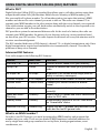
CHANNEL DOWN to change the first digit; the CHANNEL UP button increases the number and
the CHANNEL DOWN button decreases it.
English 23
5. When the first digit is correct, press ENT-1W/25W. The cursor moves to the next digit. Enter
the remaining eight digits of the MMSI number in the same way. If you make a mistake
while entering a number, press CLR-SCAN to erase the wrong number and the cursor is
moved to the left digit.
6. When the ninth digit is correct, press ENT-1W/25W.
7. The radio prompts you to enter a name for this MMSI number; the name is what you
will see in the directory list. Each name can be up to 12 characters. Use CHANNEL UP and
CHANNEL DOWN to change the first character. The channel buttons scroll through the
available characters according to the following table:
Channel Up Button
Channel Down Button
Capital letters (A through Z)
One blank space
Lower-case letters (a through z)
Numbers (0 through 9)
Punctuation (/ ‘ + -)
Punctuation (/ ‘ + -)
Numbers (0 through 9)
Lower-case letters (a through z)
One blank space
Capital letters (A through Z)
8. When the first character is correct, press ENT-1W/25W button. The cursor moves to the
next character. Enter the remaining 11 characters of the name. If the name is shorter
than 12 characters, press and hold ENT-1W/25W to complete the name entry. (If you press
and hold ENT-1W/25W without entering a name, the radio uses the MMSI number in the
directory list.) If you make a mistake while entering a number, press CLR-SCAN to erase
the wrong number and the cursor is moved to left digit.
9. When you finish entering the name, the radio displays the new MMSI number and name
and asks you to confirm. To save this directory entry, select Yes; to cancel this directory
entry, select No. The radio returns to the directory list.
10.To change an existing directory entry, select the entry you want to change.
11.To delete the directory entry, select Delete. To edit the code, select Edit, then use
CHANNEL UP and CHANNEL DOWN to edit the MMSI number and the name.
12.When you are satisfied with the directory list, select Exit to close the menu screen.
Making DSC Calls
There are essentially four different types of DSC voice calls:
Call type
What it does
When to use it
Distress
Alerts all stations that you need
assistance and sends them your
current position.
In an emergency only.
Individual
Calls a single station using the
User MMSL.
Any time you want to talk to another
station.
Group
Calls all the stations that have the Any time you want with the whole
same Group MMSL as yours.
group you are traveling with at the
same time.
All Ships
Calls all stations within range of
your radio.
24 English
Safety warnings (e.g., debris in the
water) or any urgent situation.
Suppose you are coordinating safety for a sailboat race. Before the race starts, you instruct all
the racers to enter your group MMSI number into their radios. During the race:
xx Throughout the race, you use
group calling to update the
racers on the time, race status,
and any course corrections.
xx A power boat full of
spectators comes a little too
close to the race path. You use
individual calling to contact
the power boat and advise
them to stay clear of the race.
All ships call
All ships call
xx You see a rowboat entering
the area, but since it doesn’t
have a radio, you can’t
communicate with the
Group
rowboat. You use all ships
call
calling to alert all the other
boats in the area of the
possible danger.
Individual
call
Calling a single station
(Individual Call)
To call a single station with DSC,
follow the steps below:
1. Press CALL-MENU to display the call menu.
2. Select Individual.
3. The radio displays the names listed in your directory; use CHANNEL UP and CHANNEL DOWN
to choose the directory entry you want to call and press ENT-1W/25W.
If you want to call a station that is not in your directory, select Manual. The radio
prompts you to enter the MMSI number you want to call. Enter the MMSI number the
same way you enter directory entries (see page 22) Enter all nine digits and press ENT1W/25W.
4. The radio prompts you to select a response channel. Use CHANNEL UP and CHANNEL DOWN
to scroll through the available channels. When you reach the channel you want to use for
a response, press the ENT-1W/25W button.
5. The radio displays the MMSI number you are about to call and asks you to confirm. If you
want to call the displayed MMSI number, select Send. To cancel the call, select Cancel.
6. The radio automatically switches to channel 70 to transmit the call request.
xx When the other station accepts the call, both radios switch to the selected response
channel for voice transmission.
xx If the other station cannot respond on the channel you selected, the radio displays Not
support CH.
English 25
Calling a particular group of stations (Group Call)
Group calling calls all the stations that share your group MMSI. You must have a group MMSI
programmed into the radio to make a group call, and the stations (boats) you are calling
must have this same group MMSI programmed into their radios.
1. Press CALL-MENU to display the call menu.
2. Select Group.
3. The radio prompts you to select a response channel. Use CHANNEL UP and CHANNEL DOWN
to scroll through the available channels. When you reach the channel you want to use for
a response, press ENT-1W/25W.
4. The radio asks you to confirm the call. Select Send to continue with the call or select
Cancel to cancel the call.
5. The radio switches to channel 70 to transmit the call request then automatically switches
to the designated response channel.
Calling all stations (All-Ships Call)
All ships calling contacts all DSC radios within range of your boat. You should only use all
ships calling in the event of a Safety warning (such as debris in the water) or to request
assistance in an Urgency (any situation where your vessel has a serious problem but is not
yet in distress).
1. Open the call menu.
2. Select All Ships, and then choose whether this is an Urgency call or a Safety call.
3. The radio asks you to confirm the call. Select Send to continue with the call or select
Cancel to cancel the call.
4. The radio automatically switches to channel 70 to transmit the call request then
automatically switches to channel 16, the designated response channel for all-ships
calling.
Making an automatic distress call
If you have programmed your MMSI number, your radio can transmit an automated distress
call with your current location and nature of the distress. The radio then monitors the
channel 16 for a response and repeats the distress call every few minutes until it receives an
acknowledgement.
To send an automatic distress call, press and hold DISTRESS for three seconds. If
no MMSI number has been programmed, the radio prompts you to enter your MMSI
number.
If you want to include the nature of your distress in the distress call, use the following
distress procedure:
1. Press DISTRESS.
2. The radio displays the list of distress conditions; use CHANNEL UP and CHANNEL DOWN to
choose the nature of your distress, then press and hold DISTRESS for three seconds.
Undesignated
Sinking
Fire
Adrift
Flooding
Abandoning
Collision
Piracy.Armed
Grounding
Overboard
Capsizing
26 English
3. If no MMSI number has been programmed, the radio prompts you to enter your MMSI
number.
Canceling an automatic distress call
While the radio is waiting for a response, it gives you the option of canceling the call. To
cancel the distress call, choose Cancel and press ENT-1W/25W.
Receiving a DSC call
If your radio receives an individual DSC call from another station, it sounds an incoming call
tone and displays the name or MMSI number of the station calling you. To respond to the call,
select Send: Able-Comply; the radio sends an acknowledgement and automatically switches
to the designated response channel. To reject the call, select Send: Unable-Comply; the radio
advises the other station that you are unable to respond to the call.
If the DSC request contains a response channel that you are not allowed to use, the radio
displays Not Support CH; your only response option is Send: Unable-Comply.
If the radio receives a group or all ships call, it sounds an incoming call tone and
automatically switches to the designated response channel.
Receive log
Just like your telephone’s caller ID list, your radio keeps track of the calls you receive but do
not answer. The receive log is useful if you have been off your boat or away from your radio
and want to see who has tried to contact you. The radio displays the last 10 distress calls and
the last 20 non-distress calls that it received. If you have unread incoming DSC calls, the radio
displays a Message icon. When you display all Distress and Other receiving logs, the message
icon disappears.
Press
1. Press CALL-MENU
Receive Log
to display the call
menu.
Distress
2. Select Receive Log.
Distress Log
3. Select Distress
A
123456789
to see the last
246813579
10 distress call
[Exit]
received by the radio. Select Other to see the
Back[CLR] Select[ENT]
last 20 normal calls received by the radio, then
choose from Individual, Group, or All Ships calls.
4. Calls are listed in the order they were received, with the newest call shown first. The
display blinks if there are new calls you have not reviewed.
5. Select the call you want to see the details of. Use CHANNEL UP and CHANNEL DOWN to see
all of the information. The log displays different information depending on type of call
received. See the table below for the information stored for each type of call:
88
DSC Call Type
Receive Log Information
Distress
MMSI (or name), position, time, nature code.
Distress
Acknowledge
MMSI (or name), distress MMSI, position, time, nature code.
Distress Relay
MMSI (or name), distress MMSI, position, time, nature code.
English 27
DSC Call Type
Receive Log Information
Distress Relay
Acknowledge
MMSI (or name), distress MMSI, position, time, nature code.
Geographical
MMSI (or name), category code, communication channel number.
All Ships
MMSI (or name), category code, communication channel number.
Group
MMSI (or name), category code, communication channel number.
Individual
MMSI (or name), category code, communication channel number.
Individual
Acknowledge
MMSI (or name), Completed/Unattended, category code,
communication channel number.
Test
MMSI (or name), category code.
Test Acknowledge MMSI (or name), category code.
Pos Reply
MMSI (or name), position, time, category code.
Pos Request
MMSI (or name), category code.
Pos Send
MMSI (or name), position, time, category code,
6. Press CLR-SCAN button to exit the detail screen and return to the log menu.
7. From the log menu, select Exit to close the receive log and return to the mode you were
in.
Returning a call
You can return individual calls directly from the receive log. From the call detail screen, press
CHANNEL DOWN until Call Back appears at the bottom of the display. Press ENT-1W/25W to return
that station’s call.
Test Calls
Making Test Calls (Test)
You can use the test call feature to make sure your radio is working and configured correctly.
To avoid overloading coastal receiving stations, you should limit test calls to these stations to
once a week.
##NOTE: Many coastal stations have specific frequencies and MMSI numbers you should use
for making test calls. Before making a test call to a coastal station, be sure to check the Local
Notice to Mariners (LNM), issued every week by the US Coast Guard. The LNMs for each
region are available online at http://www.navcen.uscg.gov/lnm/default.htm.
1. Press CALL-MENU to display the call menu.
2. Select Test.
Press
3. The radio displays the
names listed in your
directory; use CHANNEL
UP and CHANNEL DOWN to
choose the directory entry
you want to send a test call
to and press ENT-1W/25W
button.
28 English
Test
Test
[Manual]
JIM CASSIDY
KENT NEWMAN
Back[CLR]
16
Select[ENT]
If you want to send a test call to a station that is not in your directory, select Manual. The
radio prompts you to enter the MMSI number you want to call. Enter the MMSI number
the same way you enter directory entries (see page 22). Enter all nine digits and press
ENT-1W/25W button.
4. The radio displays the MMSI number you are about to call
Test
and asks you to confirm. If you want to call the displayed
123456789
number, select Send. To cancel the call, select Cancel.
5. The radio automatically switches to channel 70 to transmit
Send
the test call request, then switches back to the last-used
Cancel
channel.
6. When the other station acknowledges the test call, the
radio displays an acknowledgement screen.
16
Test
Acknowledged
123456789
Completed
16
USA
Exit
[CLR]
Receiving Test Calls
When another station sends you a test call, the radio displays
the test request screen.
To acknowledge the test call, select Reply.
To reject the test call, select Cancel.
Enabling automatic test call reply If you want the radio to automatically reply to all test call, you
can enable automatic test call reply.
Test
123456789
Reply
Cancel
16
1. Press and hold CALL-MENU to display the normal menu.
2. Select Setup and then Test Reply.
3. Choose Auto and press ENT-1W/25W. The radio will automatically send an
acknowledgement when it receives a test call.
Press and hold -
Setup
Test Reply
Test Reply
Auto
Manual
Back[CLR]
16
Select[ENT]
4. To disable automatic test call reply, repeat the steps above and select Manual.
Position Request and Reply
Requesting another station’s position (POS Request)
Anytime you need to know where another boat currently is—to find your boating partners,
to respond to a request for assistance, etc.—you can send a position request to their radio:
1. Press CALL-MENU to display the call menu.
English 29
2. Select DSC Call sub-menu, then select POS Request.
3. The radio displays the names listed in your directory; use CHANNEL UP and CHANNEL DOWN
to choose the directory entry you want to contact and press ENT-1W/25W. If you want to
contact a station that is not in your directory, select Manual. The radio prompts you to
enter the MMSI number you want to call. Enter the MMSI number the same way you
enter directory entries (see page 22). Enter all nine digits and press ENT-1W/25W.
4. The radio displays the MMSI number you are about to contact and asks you to confirm.
If you want to request the position of the displayed MMSI number, select Send. To cancel
the request, select Cancel.
5. When the other station responds, the radio displays the MMSI number, the longitude,
and the latitude of the other station. If your radio is connected to a chartplotter through
the NMEA OUT connection (see page 34), the position information will also be displayed
on the plotter screen.
6. If the other station does not have valid GPS data, the radio displays No Position.
Receiving a position request (Position Reply)
When another station requests your current position, the radio displays the following screen:
POS Request
JOHN HENRY
Reply
Cancel
88
A
To send your current position to the other station, select Reply; the radio transmits your
latitude and longitude to the other station. If you select Reply but the radio does not have
valid GPS data, it transmits the reply code with No Position. To reject the position request, select Cancel. Enabling automatic position reply
If you want the radio to automatically transmit your current position whenever it receives a
position request, you can enable automatic position reply. Most boaters activate automatic
position reply for safety reasons or because they subscribe to a marine towing service.
Sometimes—for example, in some competitive situations--you may not want other stations
to get your position without your manual confirmation
1. Press and hold CALL-MENU to display the normal menu.
2. Select Setup and then POS Reply.
3. Choose Auto and press ENT-1W/25W. The radio will automatically transmit your position
when it receives a position request.
4. To disable automatic position reply, repeat the steps above and select Manual.
Sending your own position (Position Send)
If your radio is connected to a GPS receiver, you can send your boat’s position to someone
else. If you are requesting assistance or using an all ships call to give a safety warning, you
can send your current position so other stations know where you are:
30 English
1. Press CALL-MENU to display the call menu.
2. Select Position Send.
3. The radio displays the names listed in your directory; use CHANNEL UP and CHANNEL DOWN
to choose the directory entry you want to contact and press ENT-1W/25W. If you want to
contact a station that is not in your directory, select Manual. The radio prompts you to
enter the MMSI number you want to call. Enter the MMSI number the same way you
enter directory entries (see page 22). Enter all nine digits and press ENT-1W/25W.
4. The radio displays the MMSI number you are about to contact and asks you to confirm. If
you want to transmit your position to the displayed MMSI number, select Send. To cancel
the transmission, select Cancel.
5. The radio transmits your MMSI number, your longitude, and your latitude to the other
station.
Putting the radio into standby
If you are leaving your radio or do not wish to answer any DSC calls, you can put your radio
in standby mode. If your radio receives an individual call, it will automatically respond with a
message that indicates your radio is currently unattended. Follow the steps below to put
your radio in standby:
Press and hold
Standby
USA
6W
MEM
01
DSC Standby
1. Display the Call menu.
2. Select Standby to place your radio in standby mode. The radio displays the standby
screen, above.
3. To cancel standby and return to the mode your radio was in, press any button.
Disabling automatic channel switching
If you are involved in a bridge-to-bridge call, you may not want the radio to automatically
switch channels when it receives a DSC call. In cases like this, you can disable automatic
channel switching. If you receive an individual call, the radio will respond with an
unattended code, just as if the radio were in Standby.
1. Press and hold CALL-MENU to display the normal menu.
2. Select Setup and then Auto CH SW.
3. Choose Off and press ENT-1W/25W. The radio will not automatically switch channels until
you reactivate this feature.
##NOTE: Use this feature with caution. Deactivating automatic switching and then forgetting it
can make it hard for you to receive DSC calls.
If you have unread incoming DSC calls, the radio displays a message icon. You will be able
to review who has called. The radio displays the last 10 distress calls and the last 20 nondistress calls it received (see the receive log on page 27).
English 31
Renaming Channels
If you discover that a marine radio channel has a different common name in your local area,
you can change the name of that channel to make it easier for you to use (see the channel
lists beginning on page 40 for the default channel names). To rename a channel, follow the
steps below:
1. Display the normal menu and choose the Setup sub-menu.
2. Select Channel Name. The screen displays the list of channels.
3. Use CHANNEL UP and CHANNEL DOWN to choose the channel you want to change and press
ENT-1W/25W.
4. Select Rename to enter a new name for this channel. The radio prompts you to enter a
new name for this channel. Each name can be up to 12 characters. Use CHANNEL UP and
CHANNEL DOWN to change the first character.
5. When the first character is correct, press ENT-1W/25W. The cursor moves to the next
character. Enter the remaining 11 characters of the name. If the name is shorter than 12
characters, press and hold ENT-1W/25W to complete the name entry. If you make a mistake
while entering a number, press CLR-SCAN to erase the wrong number and the cursor is
moved to the left digit.
6. When you finish entering the name, the radio displays the new channel name and asks
you to confirm. To save this new channel name, select Yes; to cancel the change, select
No. The radio returns to the channel list.
7. To restore a channel back to its original name, select the channel and choose Default.
8. When you are satisfied with the channel list, select Exit to close the menu screen.
Installing the Hardware
Mounting the radio
Your radio can sit at any angle in the mounting bracket so it can easily accommodate the best
location. First, determine the best place to mount the radio. For optimum performance, find a
location that can:
xx Properly support the weight of the radio, approximately 2.2 pounds or 1.1 kilograms.
You may need to use some type of anchor with the mounting screws to hold the radio,
depending on the surface.
xx Keep the battery leads as short as possible.
xx Keep the antenna lead-in wire as short as possible.
xx Allow free air flow around the heat sink on the rear of the radio.
xx Avoid interference with the ship’s compass.
32 English
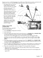
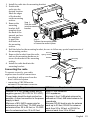
1. Install the radio into the mounting bracket.
2. Position the
radio into the
desired location.
Mark the edges
of the bracket
on the mounting
1
surface.
Step 1:
3. Remove the
Slide the radio
mounting
into the mounting
bracket drill
bracket.
template from
the back of the
manual, and use
2
the template
Step 2:
to mark the
Tighten the mounting knobs
drill holes on
to secure the radio in place.
the mounting
surface.
4. Drill the holes for the mounting bracket; be sure to follow any special requirements of
the mounting surface.
Hex nut
5. Remove the bracket from the radio, Spring washer
and use the mounting hardware to
Washer
Mounting
secure the bracket to the mounting
surface
surface.
6. Install the radio back into the
mounting bracket.
Mounting
Connecting the radio
To operate correctly, your radio
requires two electrical connections:
xx providing it with power from the
boat’s electrical system
xx connecting a VHF-FM marine
antenna to the antenna connector
bracket
Hex bolt
Power Supply Requirements
VHF Antenna Requirements
Nominal 13.8 VDC power supply with a
negative ground (10.5 VDC to 16.0 VDC).
Power leads should be kept as short as
possible. A direct connection to the power
supply is ideal.
Minimum of #14 AWG copper wire for
extensions up to 20 feet, 12 AWG wire for
extensions from 20 to 35 feet, or 10 AWG
wire for extensions from 35 to 60 feet.
Male PL-259 connector
50 Ω impedance
Minimum 4 foot, 3 dB rated antenna for
sailboats or 8 foot, 6dB rated antenna for
powerboats
Minimum RG-58 lead-in wire for antenna
leads up to 20 feet, RG-8X for antenna
leads from 20 to 35 feet, or RG-8U for
antenna leads from 35 to 60 feet.
English 33
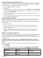
1. Connect the BLACK wire of the power cable
to the NEGATIVE (-) side of your power
Red wire
source.
(+)
2. Connect the RED wire of the power cable to
the POSITIVE (+) side of your power source.
3. NOTE: To extend the life of the radio,
use waterproof tape to seal electrical
connections.
4. Install your antenna according to the
13.8V DC
Black wire
manufacturer’s instructions.
(-)
5. If necessary, consult the FCC guidelines for
antenna separation. See Antenna Selection
and Installation on page 51 for more details. (In summary, the FCC recommends that
antennas up to 3 dB be installed a minimum of 3 feet from any occupied location;
antennas over 3 dB should be installed at least 6 feet away.)
6. Connect the PL-259 connector from the antenna lead-in wires to the SO238 connector
labeled ANTENNA on the back of your radio.
Radio connector,
SO238 (female
PL-259)
Antenna lead-in
connector,
male PL-259
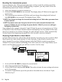
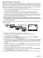
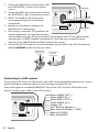
Connecting to a GPS receiver
If you connect the radio to a GPS receiver, the radio can automatically transmit your current
position during an automated distress call or during a normal DSC call.
Your radio supports a standard NMEA0183 input from a GPS receiver. Follow the steps
below to connect your radio to your GPS receiver:
13.8V DC
34 English
Brown: NMEA_OUT (-)
Green: NMEA_IN (-)
White: NMEA_OUT (+)
Yellow: NMEA_IN (+)
Orange: N/A
Red: External Speaker (+)
Blue: External Speaker (-, GND)
Black: HS-C/GND
Bare: Shield/GND
1. Connect the BARE wire of the included accessory cable to the GROUND WIRE on your
GPS receiver.
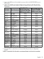
2. Connect the YELLOW wire of the included accessory cable to the GPS DATA OUTPUT
WIRE on your GPS receiver. Below is a table of common GPS receivers and the proper
connections:
GPS MFG
GPS NMEA0183
OUTPUT Wire Color
Model Number(s)
(Connect to YELLOW
WIRE on your radio)
Furuno
GP1650,
GP1850
White
Black
Furuno
GP30, GP36
White
Blue
Garmin
Fixed Mount
Models
Blue
Black
Garmin
Portable Models
Brown
Black
JRC
100 Series
Green
Black
JRC
200 Series
White
Black
Ground Wire Color
(connect to BARE
WIRE on your radio)
JRC
GPS500
Yellow
Green
Lowrance /
Eagle
Fixed Mount
Models
White
Black
Lowrance /
Eagle
Portable Models
Orange
Black
Magellan
Fixed Mount
Models
Gray
Black
Magellan
Portable Models
Orange
Black
Northstar
All Models
Yellow
Black
RayMarine
420
Yellow
Brown
RayMarine
520 / 620
Blue
Brown
RayMarine
RL Series
White
Brown
Simrad
All Models
White
Brown
Sitex
Neptune,
Nautilus
Gray
Brown
Standard
CP150 / CP150C
Green
Yellow
3. Be certain all wire connections are secure and that all open wires are adequately
covered.
##NOTE: To extend the life of the radio, use waterproof tape to seal electrical connections.
English 35
When the GPS receiver is correctly connected, the display shows GPS Data OK. If there is a
problem with the GPS connection, the display shows Check GPS. When the display shows GPS
Data OK, press ENT-1W/25W to open the GPS status screen and see detailed GPS data:
Time
Date
Course
Latitude
Longitude
06/20 11:00:00
o
208 30. 0 KT
o
35 40. 610 N
o
139 46. 564 E
16
Current
channel
Speed
Configuring the GPS
If the radio is receiving valid GPS data, it will automatically set the clock to your local time
based on the GPS location. You can adjust your local time forward or back one hour if
necessary (for example, if you are close to the border of a time zone); you can also adjust for
Daylight Savings Time.
Follow the steps below to adjust the time:
Press and hold -
Setup
Use the up and down arrows
to adjust the time by
one hour.
GPS Setup
Time Adjust
09 : 14
16
Time Adjust
Back[CLR]
Select[ENT]
1. Display the normal menu and choose the Setup sub-menu.
2. Select GPS Setup and then choose Time Adjust.
3. The display shows your current local time. To adjust the time forward one hour, use
CHANNEL UP. To adjust the time back one hour, use CHANNEL DOWN button. Press ENT1W/25W button when you are finished.
4. The display prompts you to confirm the setting: choose Set to save the new time or
Cancel to exit time setup without saving. The radio returns to the GPS Setup menu.
5. If your local area observes Daylight Savings Time, choose Daylight Save and press the
ENT-1W/25W button.
6. If Daylight Savings Time is currently in effect, select On. If Daylight Savings Time is not
currently in effect, select Off.
7. Press ENT-1W/25W. The radio activates the new time setting and returns to the GPS Setup
menu.
Connecting to a Chartplotter
Your radio provides a standard NMEA0183 GPS output that you can connect to a
chartplotter. When it receives another boat’s position data in a DSC call, the radio sends the
position data to the chartplotter so you can see the location:
1. Connect the BROWN wire of the accessory cable to the NEGATIVE (-) wire of your
chartplotter’s NMEA data INPUT.
36 English
2. Connect the WHITE wire of the accessory cable to the POSITIVE (+) wire of your
chartplotter’s NMEA data INPUT
3. Be certain all wire connections are secure and that all open wires are adequately
covered.
##NOTE: To extend the life of the radio, use waterproof tape to seal electrical connections.
Connecting to an External Speaker
You can use an external speaker to monitor the radio from a different part of your boat or in
a noisy environment. If you adjust the VOLUME-PWR knob on the radio, it will also adjust the
external speaker volume.
Your radio supports an external speaker with the following specifications:
xx Minimum impedance of 4 Ohms
xx Minimum power handling of 10 Watts
1. Connect the BLUE wire of the accessory cable to the GROUND WIRE of your external
speaker.
2. Connect the RED wire of the accessory cable to the POSITIVE (+) WIRE of your external
speaker.
3. Be certain all wire connections are secure and that all open wires are adequately
covered.
##NOTE: To extend the life of the radio, use waterproof tape to seal electrical connections.
Maintenance and Troubleshooting
Due to its rugged design, your radio requires very little maintenance. However, it is a
precision electronic instrument, so you should follow a few precautions:
xx If the antenna has been damaged, you should not transmit except in the case of an
emergency. A defective antenna may cause damage to your radio.
xx You are responsible for continued FCC technical compliance of your radio.
xx You should arrange for periodic performance checks with your dealer.
Problem
Things to Try
The radio won’t power on.
Check the power connections.
Check the fuse.
Check the master battery switch and branch circuit
that connect to the radio.
The radio won’t transmit.
Make sure you are not in weather or scan mode.
Make sure you are not trying to transmit on a receiveonly channel (see the channels and frequency tables
beginning on page 40).
Make sure you are transmitting at the correct power
level for this channel (see the channels and frequency
tables beginning on page 40).
Make sure the duration of each transmission is less
than 5 minutes.
English 37
Problem
Things to Try
Noise comes out of the speaker
Adjust the squelch level; it is probably too low.
all the time
I can’t hear anything (no
volume) from the speaker.
Adjust the squelch level; it is probably too high.
I can transmit, but no one can
hear me.
Check your UIC channel settings (see Setting the UIC
channel mode (USA/CAN/INT) on page 10).
The display flashes, and I don’t
know why.
The display will flash if the radio is in a watch mode or
in scan mode. Try turning off scanning, Weather Alert
Watch, or Triple/Dual Watch (see page 10.)
I can’t read the display.
Adjust the contrast and backlight brightness level (see
page 20)
The display is too bright at
night.
Adjust the backlight brightness level.
Turn off the radio; hold CALL-MENU button and turn it
back on (see page 20)
I can’t see any words on the
display.
Reset the radio back to the default brightness level:
turn off the radio; hold the CALL-MENU button and
turn it back on.
I’m not getting any GPS data
on my display.
Make sure your GPS receiver is correctly
connected (see Connecting to a GPS receiver,
page 34).
Make sure your GPS receiver is working properly.
Make sure that your GPS receiver supports the
NMEA parameters described in NMEA Operation
on page 49.
I’m not getting any hazard
alerts.
Make sure Weather Alert Watch is turned on.
Check to make sure the FIPS codes in your radio
include your current location (see Using FIPS
codes for weather alerts on page 19).
I’m getting all the hazard
alerts, not just the ones for
my area.
Check to make sure the FIPS codes in your radio
were entered correctly (see Using FIPS codes for
weather alerts on page 19).
Sometimes the Weather Alert Watch may catch
a hazard alert in the middle of the broadcast and
miss which FIPS codes are affected. For your safety, the radio triggers the alert tone and switches to
the weather channel when this happens.
I can’t make Group DSC
calls.
Make sure the Group MMSI was entered correctly.
Where can I find my radio’s
serial number?
Look on the right side of the radio (the side with the
microphone cord), behind the mounting bracket.
38 English
Problem
Things to Try
The radio won’t let me enter
my User MMSI. What do I
do?
Contact customer service.
Engine Noise Suppression
Interference from the noise generated by the electrical systems of engines is sometimes a
problem with radios. Your radio has been designed to be essentially impervious to ignition
noise and alternator noise. However, in some installations it may be necessary to take
measures to further reduce the effect of noise interference. Your radio’s DC battery wires,
antenna lead, and accessory cables should be routed away from the engine and engine
compartment, and from power cabling carrying high currents. In severe cases of noise
interference, it may be necessary to install a noise suppression kit. Contact the dealer where
you purchased the radio for more information.
Specifications
All speficifations are subject to change without notice.
Radio Specifications
General
Controls
Volume-Pwr, Squelch
Status Indicators
Transmit power, Scan mode, Triple Watch mode,
Battery High, Battery low, USA, CAN, INT, Alert,
Memory, GPS, Message, Weather band, GPS status
and Channel Display
Display
LCD (Full Dot Matrix)
Buttons
ENT-1W/25W, Channel UP, Channel DOWN, CALLMENU, WX-MEM, CLR-SCAN, 16/9-TRI, DISTRESS,
and SCAN/MEM
Connectors and Cables
Antenna, accessory, and DC power
Size
H 75 mm x W 167 mm x L 129 mm (without Heat Sink)
H 2.95 inches x W 6.58 inches x L 5.08 inches
Weight
1.0 kg (2.2 pounds)
Supply Voltage
Nominal 13.8V DC, negative ground (10.5 VDC to 16.0
VDC)
Standard Accessories
Mounting bracket and hardware, microphone hanger,
Antenna Impedance
50 Ω nominal
Microphone
Rugged 2 kΩ condenser mic element with coiled cord
Speaker
1.77 inch, 8 Ω
Operating Temperature
Range
–20 °C to + 50 °C (–4 °F to +122 °F)
English 39
General
Shock and Vibration
Meets or exceeds EIA standards, RS152B and
RS204C
FCC Approvals
Type accepted under part 80 of the Rules; meets Great
Lakes Agreement and party boat requirements
Transmitter
Power Output
1 watt or 25 watt (user selectable)
Power Requirement
25 watts output: [email protected] DC
Modulation
±5 kHz deviation
Hum and Noise Signal-toNoise
45 dB@1 kHz with 3 kHz deviation with 1000 Hz
modulating frequency (nominal)
Audio Distortion
Less than 8% with 3 kHz deviation with 1000 Hz
modulating frequency
Spurious Suppression
–25 dBm @ Hi, –25 dBm @ Lo
Output Power Stabilization
Built-in automatic level control (ALC)
Frequency Range
156 to 158 MHz
Frequency Stability
±10 ppm @ –20°C to + 50°C
Receiver
Frequency Range
156 to 163 MHz
Sensitivity
0.25 μV for 12 dB SINAD (nominal)
Circuit
Dual Conversion Super Heterodyne PLL (Crystal for
DSC)
Squelch Sensitivity
0.2 μV Threshold
Spurious Response
75 dB (nominal)
Adjacent Channel Selectivity
78 dB @ ±25 kHz (nominal)
Audio Output Power
2.5 watts (10% Distortion, 8 Ω load)
Power Requirement
360 mA @ 13.8V DC at squelched, 920 mA @ 13.8V
DC at maximum audio output
IF Frequencies
1st 41.925 MHz, 2nd 455 kHz (1st 21.7 MHz, 2nd 455
kHz for DSC)
Reference Tables
##This radio does not support AIS channels.
Channel descriptions and what they mean
The table below lists the display name or channel description used in the following tables
and what each description means.
40 English
Channel name/description
Used for:
DISTRESS SAFETY AND
CALLING
primarily emergency messages and distress calls
INTERSHIP SAFETY
safety messages from one ship to another, or from a
ship to Coast Guard aircraft
NON-COMMERCIAL
(recreational or voluntary
ships only)
messages about the needs of the ship, including fishing
reports, rendezvous, scheduling repairs and berthing
information
COMMERCIAL (working
ships only)
messages about the needs of the ship or the business
the ship is engaged in
PUBLIC
CORRESPONDENCE/
MARINE OPERATOR
calls to the marine operator at a public coast station.
Marine operators can connect you to the telephone
network so you can make and receive calls. (There is
usually a charge for this service.)
PORT OPERATIONS/VTS
(vessel traffic system)
messages about the movement and safety of ships in or
near ports, locks or waterways. In certain major ports,
some channels may be restricted to specific types of
port operations messages.
NAVIGATIONAL/BRIDGE
TO BRIDGE
messages about ship navigation, for example, passing
or meeting other ships, maneuvering through locks,
or navigating around drawbridges. Messages must be
short!
STATE CONTROL
messages about government regulation and control,
boating activities, or assistance to ships; also used to
talk to ships and coast stations operated by state or local
governments
DIGITAL SELECTIVE
CALLING
DSC signals only (no voice communications allowed at
any time)
US Marine Channels and Frequencies
Ch No.
1A*
RX Freq
156.0500
TX Freq
156.0500
Status
Simplex
5A
156.2500
156.2500
Simplex
6
7A
8
9
10
11
12
156.3000
156.3500
156.4000
156.4500
156.5000
156.5500
156.6000
156.3000
156.3500
156.4000
156.4500
156.5000
156.5500
156.6000
Simplex
Simplex
Simplex
Simplex
Simplex
Simplex
Simplex
Name on display
Vessel traffic system/
Commercial
Vessel traffic system/
Commercial
Inter-ship safety
Commercial
Commercial
Non commercial
Commercial
Vessel traffic system
Vessel traffic system
English 41
Ch No.
13
14
15
16
17
18A
19A
20
20A
RX Freq
156.6500
156.7000
156.7500
156.8000
156.8500
156.9000
156.9500
161.6000
157.0000
TX Freq
156.6500
156.7000
Inhibit
156.8000
156.8500
156.9000
156.9500
157.0000
157.0000
Status
Simplex, 1W
Simplex
Receive Only
Simplex
Simplex, 1W
Simplex
Simplex
Duplex
Simplex
Name on display
Bridge to bridge
Vessel traffic system
Environmental
Distress, Safety, Calling
Govt maritime control
Commercial
Commercial
Port operation
Port operation
21A
22A
23A
24
25
26
27
28
63A
65A
66A
67
68
69
70
71
72
73
74
75
76
77
78A
79A
80A
81A
82A
83A
84
157.0500
157.1000
157.1500
161.8000
161.8500
161.9000
161.9500
162.0000
156.1750
156.2750
156.3250
156.3750
156.4250
156.4750
(156.5250
156.5750
156.6250
156.6750
156.7250
156.775
156.825
156.8750
156.9250
156.9750
157.0250
157.0750
157.1250
157.1750
161.8250
157.0500
157.1000
157.1500
157.2000
157.2500
157.3000
157.3500
157.4000
156.1750
156.2750
156.3250
156.3750
156.4250
156.4750
156.5250)
156.5750
156.6250
156.6750
156.7250
156.7750
156.8250
156.8750
156.9250
156.9750
157.0250
157.0750
157.1250
157.1750
157.2250
Simplex
Simplex
Simplex
Duplex
Duplex
Duplex
Duplex
Duplex
Simplex
Simplex
Simplex
Simplex, 1W
Simplex
Simplex
DSC Only
Simplex
Simplex
Simplex
Simplex
Simplex, 1W
Simplex, 1W
Simplex, 1W
Simplex
Simplex
Simplex
Simplex
Simplex
Simplex
Duplex
Coast guard only
Coast guard
Coast guard only
Marine operator
Marine operator
Marine operator
Marine operator
Marine operator
Vessel traffic system
Port operation
Port operation
Bridge to bridge
Non commercial
Non commercial
DSC
Non commercial
Non commercial (ship-ship)
Port operation
Port operation
Port operation
Port operation
Port operation (ship-ship)
Non commercial
Commercial
Commercial
Government
Government
Coast guard
Marine operator
42 English
Ch No.
85
86
87**
88**
RX Freq
161.8750
161.9250
157.3750
157.4250
TX Freq
157.2750
157.3250
157.3750
157.4250
Status
Duplex
Duplex
Simplex
Simplex
Name on display
Marine operator
Marine operator
Marine operator
Commercial (ship-ship)
*A indicates simplex use of the ship station transmit side of an international duplex channel,
and that operations are different from that of international operations on that channel.
**Channels 87 & 88 revert from duplex to simplex operation. AIS channels are not supported.
Canadian Marine Channels and Frequencies
Ch No.
1
2
3
4A
5A
6
7A
8
9
10
11
12
13
14
15
16
17
18A
19A
20
21A
22A
23
24
25
26
27
28
RX Freq
160.6500
160.7000
160.7500
156.2000
156.2500
156.3000
156.3500
156.4000
156.4500
156.5000
156.5500
156.6000
156.6500
156.7000
156.7500
156.8000
156.8500
156.9000
156.9500
161.6000
157.0500
157.1000
161.7500
161.8000
161.8500
161.9000
161.9500
162.0000
TX Freq
156.0500
156.1000
156.1500
156.2000
156.2500
156.3000
156.3500
156.4000
156.4500
156.5000
156.5500
156.6000
156.6500
156.7000
156.7500
156.8000
156.8500
156.9000
156.9500
157.0000
157.0500
157.1000
157.1500
157.2000
157.2500
157.3000
157.3500
157.4000
Status
Duplex
Duplex
Duplex
Simplex
Simplex
Simplex
Simplex
Simplex
Simplex
Simplex
Simplex
Simplex
Simplex, 1W
Simplex
Simplex, 1W
Simplex
Simplex, 1W
Simplex
Simplex
Duplex, 1W
Simplex
Simplex
Duplex
Duplex
Duplex
Duplex
Duplex
Duplex
Name on display
Marine operator
Marine operator
Marine operator
Canadian coast guard
Vessel traffic system
Inter-ship safety
Commercial
Commercial
Boater calling channel
Commercial
Vessel traffic system
Vessel traffic system
Bridge to bridge
Vessel traffic system
Environmental
Distress, Safety, Calling
State control
Commercial
Canadian coast guard
Port operation
Canadian coast guard
Canadian coast guard
Marine operator
Marine operator
Marine operator
Marine operator
Marine operator
Marine operator
English 43
Ch No.
60
61A
62A
63A
64
64A
65A
66A
67
68
69
70
71
72
73
74
75
76
77
78A
79A
80A
81A
82A
83
83A
84
85
86
87
88
RX Freq
160.6250
156.0750
156.1250
156.1750
160.8250
156.2250
156.2750
156.3250
156.3750
156.4250
156.4750
(156.5250
156.5750
156.6250
156.6750
156.7250
156.7750
156.8250
156.8750
156.9250
156.9750
157.0250
157.0750
157.1250
161.7750
157.1750
161.8250
161.8750
161.9250
157.3750
157.4250
TX Freq
156.0250
156.0750
156.1250
156.1750
156.2250
156.2250
156.2750
156.3250
156.3750
156.4250
156.4750
156.5250)
156.5750
156.6250
156.6750
156.7250
156.7750
156.8250
156.8750
156.9250
156.9750
157.0250
157.0750
157.1250
157.1750
157.1750
157.2250
157.2750
157.3250
157.3750
157.4250
Status
Duplex
Simplex
Simplex
Simplex
Duplex
Simplex
Simplex
Simplex, 1W
Simplex
Simplex
Simplex
DSC Only
Simplex
Simplex
Simplex
Simplex
Simplex, 1W
Simplex, 1W
Simplex, 1W
Simplex
Simplex
Simplex
Simplex
Simplex
Duplex
Simplex
Duplex
Duplex
Duplex
Simplex
Simplex
Name on display
Marine operator
Canadian coast guard
Canadian coast guard
Port operation
Marine operator
Port operation
Port operation
Port operation
Bridge to bridge
Non commercial
Non commercial
DSC
Non commercial
Non commercial
Port operation
Port operation
Port operation
Port operation
Port operation
Inter ship
Inter ship
Inter ship
Canadian coast guard
Canadian coast guard
Canadian coast guard
Canadian coast guard
Marine operator
Marine operator
Marine operator
Port operation
Port operation
International Marine Channels and Frequencies
Ch No.
1
2
3
44 English
RX Freq
160.6500
160.7000
160.7500
TX Freq
156.0500
156.1000
156.1500
Status
Duplex
Duplex
Duplex
Name on display
Marine operator
Marine operator
Marine operator
Ch No.
4
5
6
7
8
9
10
11
12
13
14
15
16
17
18
19
20
21
22
23
24
25
26
27
28
60
61
62
63
64
65
66
67
68
69
70
71
72
RX Freq
160.8000
160.8500
156.3000
160.9500
156.4000
156.4500
156.5000
156.5500
156.6000
156.6500
156.7000
156.7500
156.8000
156.8500
161.5000
161.5500
161.6000
161.6500
161.7000
161.7500
161.8000
161.8500
161.9000
161.9500
162.0000
160.6250
160.6750
160.7250
160.7750
160.8250
160.8750
160.9250
156.3750
156.4250
156.4750
(156.5250)
156.5750
156.6250
TX Freq
156.2000
156.2500
156.3000
156.3500
156.4000
156.4500
156.5000
156.5500
156.6000
156.6500
156.7000
156.7500
156.8000
156.8500
156.9000
156.9500
157.0000
157.0500
157.1000
157.1500
157.2000
157.2500
157.3000
157.3500
157.4000
156.0250
156.0750
156.1250
156.1750
156.2250
156.2750
156.3250
156.3750
156.4250
156.4750
(156.5250)
156.5750
156.6250
Status
Duplex
Duplex
Simplex
Duplex
Simplex
Simplex
Simplex
Simplex
Simplex
Simplex
Simplex
Simplex, 1W
Simplex
Simplex, 1W
Duplex
Duplex
Duplex
Duplex
Duplex
Duplex
Duplex
Duplex
Duplex
Duplex
Duplex
Duplex
Duplex
Duplex
Duplex
Duplex
Duplex
Duplex
Simplex
Simplex
Simplex
DSC Only
Simplex
Simplex
Name on display
Marine operator
Marine operator
Inter-ship safety
Marine operator
Commercial (ship-ship)
Boater calling channel
Commercial
Vessel traffic system
Vessel traffic system
Bridge to bridge
Vessel traffic system
Environmental
Distress, Safety, Calling
Govt maritime control
Port operation
Commercial
Port operation
Port operation
Port operation
Marine operator
Marine operator
Marine operator
Marine operator
Marine operator
Marine operator
Marine operator
Marine operator
Marine operator
Marine operator
Marine operator
Marine operator
Marine operator
Bridge to bridge
Non commercial
Non commercial
DSC
Non commercial
Non commercial
English 45
Ch No.
73
74
75
76
77
78
79
80
81
82
83
84
85
86
87*
88*
RX Freq
156.6750
156.7250
156.7750
156.8250
156.8750
161.5250
161.5750
161.6250
161.6750
161.7250
161.7750
161.8250
161.8750
161.9250
157.3750
157.4250
TX Freq
156.6750
156.7250
156.7750
156.8250
156.8750
156.9250
156.9750
157.0250
157.0750
157.1250
157.1750
157.2250
157.2750
157.3250
157.3750
157.4250
Status
Simplex
Simplex
Simplex, 1W
Simplex, 1W
Simplex
Duplex
Duplex
Duplex
Duplex
Duplex
Duplex
Duplex
Duplex
Duplex
Simplex
Simplex
Name on display
Port operation
Port operation
Port operation
Port operation
Port operation (ship-ship)
Port operation
Port operation
Port operation
Port operation
Port operation
Port operation
Marine operator
Marine operator
Marine operator
Marine operator
Marine operator
*Channels 87 & 88 revert from duplex to simplex operation. AIS channels are not supported.
Weather Channels and Frequencies (US, CAN, and INT)
Ch No.
WX01
WX02
WX03
WX04
WX05
WX06
WX07
WX08
WX09
WX10
RX Freq
162.5500
162.4000
162.4750
162.4250
162.4500
162.5000
162.5250
161.6500
161.7750
163.2750
Name on display
162.550 MHz
162.400 MHz
162.475 MHz
162.425 MHz
162.450 MHz
162.500 MHz
162.525 MHz
161.650 MHz
161.775 MHz
163.275 MHz
Emergency Alert System (SAME) Information
Types of events
xx A WARNING is an event that alone poses a significant threat to public safety and/or
property, probability of occurrence and location is high, and the onset time is relatively
short.
xx A WATCH meets the classification of a warning, but either the onset time, probability of
occurrance, or location is uncertain.
46 English
xx An EMERGENCY is an event that, by itself, would not kill or injure or do property damage,
xx
but indirectly may cause other things to happen that result in a hazard. For example, a
major power or telephone loss in a large city alone is not a direct hazard, but disruption
to other critical services could create a variety of conditions that could directly threaten
public safety.
A STATEMENT is a message containing follow up information to a warning, watch, or
emergency.
Event
Blizzard Warning
SAME Code
BZW
Type
Warning
Coastal Flood Watch
Coastal Flood Warning
Dust Storm Warning
Flash Flood Watch
Flash Flood Warning
Flash Flood Statement
Flood Watch
Flood Warning
Flood Statement
Freeze Warning
High Wind Watch
High Wind Warning
Hurricane Watch
Hurricane Warning
Hurricane Statement
Severe Thunderstorm Watch
Severe Thunderstorm Warning
Severe Weather Statement
Special Marine Warning
Special Weather Statement
Tornado Watch
Tornado Warning
Tropical Storm Watch
Tropical Storm Warning
Tsunami Watch
Tsunami Warning
Winter Storm Watch
Winter Storm Warning
National Information Center
Avalanche Watch
CFA
CFW
DSW
FFA
FFW
FFS
FLA
FLW
FLS
FZW
HWA
HWW
HUA
HUW
HLS
SVA
SVR
SVS
SMW
SPS
TOA
TOR
TRA
TRW
TSA
TSW
WSA
WSW
NIC
AVA
Watch
Warning
Warning
Watch
Warning
Statement
Watch
Warning
Statement
Warning
Watch
Warning
Watch
Warning
Statement
Watch
Warning
Statement
Warning
Statement
Watch
Warning
Watch
Warning
Watch
Warning
Watch
Warning
Statement
Watch
English 47
Event
Avalanche Warning
Child Abduction Emergency
Civil Danger Warning
Civil Emergency Message
Earthquake Warning
Immediate Evacuation
Fire Warning
Hazardous Material Warning
Law Enforcement Warning
Local Area Emergency
911 Telephone Outage Emergency
Nuclear Power Plant Warning
Radiological Hazard Warning
Shelter In-Place Warning
Volcano Warning
Administrative Message
Practice/Demo
Required Monthly Test
Required Weekly Test
Biological Hazard Warning
Boil Water Warning
Chemical Hazard Warning
Dam Watch
Dam Break Warning
Contagious Disease Warning
Emergency Action Notification
Emergency Action Termination
Evacuation Watch
Food Contamination Warning
Flash Freeze Warning
Iceberg Warning
Industrial Fire Warning
Landslide Warning
National Audible Test
Network Notification Message
National Periodic Test
National Silent Test
Power Outage Advisory
48 English
SAME Code
AVW
CAE
CDW
CEM
EQW
EVI
FRW
HMW
LEW
LAE
TOE
NUW
RHW
SPW
VOW
ADR
DMO
RMT
RWT
BHW
BWW
CHW
DBA
DBW
DEW
EAN
EAT
EVA
FCW
FSW
IBW
IFW
LSW
NAT
NMN
NPT
NST
POS
Type
Warning
Statement
Warning
Statement
Warning
Warning
Warning
Warning
Warning
Statement
Statement
Warning
Warning
Warning
Warning
Statement
Test
Test
Test
Warning
Warning
Warning
Watch
Warning
Warning
Warning
Statement
Watch
Warning
Warning
Warning
Warning
Warning
Test
Statement
Test
Test
Statement
Event
Wild Fire Watch
Wild Fire Warning
Unrecognized Watch
Unrecognized Emergency
Unrecognized Statement
Unrecognized Warning
SAME Code
WFA
WFW
**A
**E
**S
**W
Type
Watch
Warning
Watch
Statement
Statement
Warning
No Response Event Code
TXB
Transmitter Backup On
TXF
Transmitter Carrier On
TXO
Transmitter Carrier On
TXP
Transmitter Primary On
NMEA Operation
This radio supports NMEA0183 version 4.01.
NMEA Input
If you have difficulty getting your radio to receive data from your GPS receiver, check the
device’s configuration. It should be set to the following parameters:
Baud rate
4800 bps
Data bits
8
Parity
None
Stop bits
1
Data amplitude
Over 2.0 V
Drive capability
Over 10 mA
The radio supports RMC, GLL, GNS, GGA and ZDA sentences. When these sentences are
received, the radio displays latitude/longitude, date, time, course, and speed. If any sentence
except an RMC or GLL sentence is received, the radio uses the information based on the
following priority order.
xx Status:RMC > GLL > GNS > GGA
xx Latitude/Longitude:RMC > GLL > GNS > GGA
xx UTC Time: RMC > GLL > GNS > GGA > ZDA
xx Date: RMC > ZDA
xx Speed / Course:RMC
##NOTE 1:
If the radio receives only a GLL sentence, the radio does not display the current
speed, course, and date.
##Note 2:
If the radio receives both RMC and GLL sentences, the radio uses only the RMC
sentence.
##Note 3:
Status data is used to check whether the GPS data is valid or invalid.
English 49
NMEA Output
When the radio receives a DSC call (Distress, Position Reply, or Position Send), it outputs a
DSC/DSE sentence from the NMEA output port.
##NOTE: When the radio receives a distress call, it outputs a sentence in the following format.
xx $CDDSC,12,3081234000,,07,00,0354013946,0657,,,S,E*6D
xx $CDDSE,1,1,A,3081234000,00,60875646*13
Regulations and Safety Warnings
Maritime radio services operation
Warning! This transmitter will operate on channels/frequencies that have restricted use in
the United States. The channel assignments include frequencies assigned for exclusive use of
the U.S. Coast Guard, use in Canada, and use in international waters. Operation on these frequencies without proper authorization is strictly forbidden. See the channel tables beginning
on page 40 for a list of available channels and their uses. If you are still not certain which
channels to use, see the FCC maritime radio page at the FCC website (http:// wireless.fcc.
gov/marine/) or contact the FCC Call Center at 1-888-CALLFCC. For individuals requiring a
license, such as commercial users, you should obtain a license application from your nearest
FCC field office (for US users) or Industry Canada (for Canadian users).
Basic radio guidelines
You should familiarize yourself with the rules on marine radios and be aware of which rules
apply to your boat. Complete guidelines for all ship and marine radio types can be found
at the US Coast Guard website under the topic Radio Info for Boaters (the direct link is
http://www.navcen.uscg. gov/marcomms/boater.htm). Here are a few guidelines that affect
nearly all boaters.
• If you have a VHF radio on your boat, you must maintain a watch on channel 16 (156.800
MHz) whenever the radio is not being used to communicate. Effective from 2004, if a radio
is carried, it must be turned on and set to channel 16 whenever your vessel is underway.
• If you hear a distress call, wait a few minutes to let a shore station or Coast Guard vessel respond. If no other station has responded after 5 minutes, you must respond to the
distress call.
• Do not make false mayday or distress calls as a prank or to test your radio. (This is essentially like making a false 9-1-1 call; you may be subject to fines.)
FCC Information
This device complies with Part 15 of the FCC Rules. Operation is subject to the condition that
this device does not cause harmful interference.
Unauthorized changes or modifications to this equipment may void compliance with the FCC
Rules. Any change or modify cation must be approved in writing by Uniden.
Any changes or modifications not expressly approved by the party responsible for compliance could void the user’s authority to operate this device.
50 English
To maintain compliance with FCC RF exposure requirements, the radio must be used with
a maximum duty cycle not exceeding 50% in typical push-to-talk radio use time. DO NOT
transmit for more than 50% of total radio use time.
Lead warning
The cords on this product and/or accessories contain lead, a chemical known to the State of
California to cause birth defects or other reproductive harm. Wash hands after handling.
Uniden works to reduce lead content in our PVC coated cords in our products and accessories.
Antenna Selection and Installation
Your UM415 has been designed to accommodate all of the popular marine VHF antennas.
However, the selection and the installation of the antenna is the responsibility of the user or
installer.
The FCC has determined that excessive radiation poses a health risk to people near radio
transmitting antennas. Therefore, the antenna used with this radio should be installed using
the following guidelines to ensure a suitable distance between the antenna and persons close
by.
• Small whip antennas (3 dB) or smaller should be installed keeping at least a two foot separation distance between the radiating element and people.
• Medium antennas (6 dB) should be installed keeping at least a three foot separation distance.
• Larger antennas (9 dB) should be installed keeping at least a four foot separation distance.
• No person should touch the antenna or come into the separation distance when the radio
is transmitting.
Three Year Limited Warranty
WARRANTOR: UNIDEN AMERICA CORP. (“Uniden”)
ELEMENTS OF WARRANTY: Uniden warrants, for three years, to the original retail owner,
this Uniden roduct to be free from defects in materials and craftsmanship with only the limitations or exclusions set out below.
WARRANTY DURATION: This warranty to the original user shall terminate and be of no
further effect 36 months after the date of original retail sale. The warranty is invalid if the
Product is (A) damaged or not maintained as reasonable or necessary, (B) modified, altered,
or used as part of any conversion kits, subassemblies, or any configurations not sold by Uniden, (C) improperly installed, (D) serviced or repaired by someone other than an authorized
Uniden service center for a defect or malfunction covered by this warranty, (E) used in any
conjunction with equipment or parts or as part of any system not manufactured by Uniden,
or (F) installed or programmed by anyone other than as detailed by the Operating Guide for
this product.
STATEMENT OF REMEDY: In the event that the product does not conform to this warranty at
any time while this warranty is in effect, warrantor will either, at its option, repair or replace
the defective unit and return it to you without charge for parts, service, or any other cost
(except shipping and handling) incurred by warrantor or its representatives in connection
English 51
with the per-formance of this warranty. Warrantor, at its option, may replace the unit with a
new or refur-bished unit. THE LIMITED WARRANTY SET FORTH ABOVE IS THE SOLE AND
ENTIRE WARRANTY PERTAINING TO THE PRODUCT AND IS IN LIEU OF AND EXCLUDES
ALL OTHER WARRANTIES OF ANY NATURE WHATSOEVER, WHETHER EXPRESS, IMPLIED
OR ARISING BY OPERATION OF LAW, INCLUDING, BUT NOT LIMITED TO ANY IMPLIED
WARRANTIES OF MERCHANTABILITY OR FITNESS FOR A PARTICULAR PURPOSE. THIS
WARRANTY DOES NOT COVER OR PROVIDE FOR THE REIMBURSEMENT OR PAYMENT OF
INCIDENTAL OR CONSEQUENTIAL DAMAGES. Some states do not allow this exclusion or
limitation of incidental or consequential damages so the above limitation or exclusion may
not apply to you.
LEGAL REMEDIES: This warranty gives you specific legal rights, and you may also have
other rights which vary from state to state. This warranty is void outside the United States of
America.
PROCEDURE FOR OBTAINING PERFORMANCE OF WARRANTY: If, after following the instructions in this Operating Guide you are certain that the Product is defective, pack the Product
carefully (preferably in its original packaging). Include evidence of original purchase and a
note describing the defect that has caused you to return it. The Product should be shipped
freight prepaid, by traceable means, or delivered, to warrantor at:
Uniden America Corporation
Parts and Service Division
4700 Amon Carter Boulevard
Fort Worth, TX, 76155
52 English