1
9800 Martel Road
Lenoir City, TN 37772
www.ps-engineering.com
PMA6000-Series
PMA6000M, PMA6000M-C
Audio Control Panel
with Monaural Intercom
and optional Marker Beacon
Pilot’s Guide
and
Operation Manual
FAA-TSO C50c, C35d
US Patent 4,941,187: 5,903,277: 6,160,496: 6,493,459
202-066-0002
Revision 3
August 2007
PMA6000 –Mono Pilot Guide
202-066-0002
1
OPERATION
GENERAL INFORMATION
SCOPE
This section provides detailed operating instructions for the PS
Engineering PMA6000C, and PMA6000M-C, Audio Selector
Panel/Intercom Systems. Please read it carefully before using
the equipment so that you can take full advantage of its capabilities.
This guide is divided into four sections covering the basic operating areas of the PMA6000 systems. They are: Audio Selector, Audio Selection, Intercom, and Marker Beacon Receiver
(PMA6000M-C only).
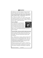
Audio Selector (All models)
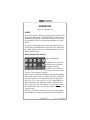
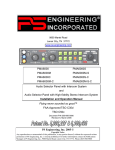
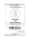
Figure 1 Audio Selector
Through the use of two momentary and seven latched,
push-button, back-lit
switches, it is possible to select any or all receiver audio.
C1 and C2 are momentary switches.
When selected, an internal backlight will illuminate indicating
which audio source is selected. Because the rotary switch controls what transceiver is being heard by the pilot and copilot
(the crew), "Cl" (Com 1) and "C2" (Com 2) push-buttons are
of the momentary type and do not remain in when selected.
This is also part of the "auto function." You will always hear
the audio from the transceiver that is selected by the rotary mic
selector switch.
The users can identify which receivers are selected by noting
which push-button switches are illuminated. Push buttons la-
2
202-066-0002
Rev. 3, August 2007
beled Nl (Nav 1), N2 (Nav 2), D (DME), M (Marker), A
(ADF), AX (auxiliary), and S (Speaker) are "latched" type
switches. When one of these buttons is pressed, it will stay in
the "in" position. Press the switch again and it will be in the
"out" position and remove that receiver from the audio. While
selected, the switch will also be annunciated by an internal
lamp.
NOTE: In Split Mode, no pushbuttons will be active. The only
audio selected is from Com 1 and Com 2, as indicated by their
respective lamps.
Speaker Amplifier
The "S" in the push-button section stands for speaker. This
switch will place all selected audio on the cockpit speaker
when this switch is selected. NOTE: with the exception of
unswitched unmuted inputs (Altimeter warning), the speaker
amplifier is not active in the "Split Mode." To reduce power
consumption and internal heat buildup in the avionics stack,
switch off the speaker amplifier when not in use.
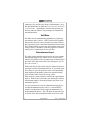
Mic Selector Switch (Fail Safe Operation)
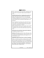
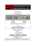
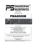
Figure 2 Mic Selector
Unit power is turned on and off by the
Mic selector switch. In the OFF or
"FAIL-SAFE" position, the pilot is connected directly to Com 1 allowing
transmit and receive capability regardless of unit condition. Any time power
is removed or turned OFF, the audio selector will be placed in the fail-safe mode. In fail-safe mode,
the pilot headset is connected directly to Com 1. The first position clockwise from OFF is COM 1. Both pilot and copilot will
be connected to the Com l transceiver.
Both the pilot and copilot have transmit capabilities on the selected
transceiver. All hear the selected audio if the intercom is in the
ALL mode. Only the person who presses their Push To Talk
PMA6000 –Mono Pilot Guide
202-066-0002
3
(PTT), will be heard over the aircraft radio. Turning the rotary
switch to the COM 2 position will place pilot and copilot on
Com 2.
The PMA6000-Series has an automatic selector mode. Audio
from the selected transceiver is automatically heard in the
headsets and speaker (when selected). You can check this
function by switching from COM 1 to COM 2 and watch the
selected audio light on the selector change from C1 to C2. This
ensures the pilot will never transmit on a radio that he is not
listening to.
When switching the mic selector rotary switch from COM 1 to
COM 2, while COM 2 audio had been selected, Com 1 audio
will continue to be heard. This eliminates the pilot having to
switch Com 1 audio back on, if desired.
When switching from COM 1 to COM 2 while Com 2 has NOT
been selected, Com 1 audio will be switched off. In essence,
switching the mic selector will not effect the selection of Com
audio.
Placing the mic selector switch in the COM 3 position connects the
pilot and copilot to that radio. This is similar to COM 1 and COM 2,
except that the swap mode is not active.
Important: When the mic selector is in the full counter clockwise position, the PMA6000 power is removed, and it is in the
FAIL-SAFE mode. The pilot headset and microphone are connected directly to Com 1.
Swap Mode (Switch from Com 1 to Com 2 remotely)
With a yoke mounted, momentary switch, the pilot can change
from the current Com transceiver to the other by depressing
this switch. When "Swap Mode" is active, an LED annunciator
will illuminate, indicating that the Mic Selector switch position
is no longer valid. To cancel "Swap Mode," the pilot may either press the yoke mounted switch again, or turn the Mic Selector Switch to the Com that is active.
4
202-066-0002
Rev. 3, August 2007
Split Mode
Turning the rotary switch to COM 1/2 puts the PMA6000 into
"Split Mode". This places the pilot on Com 1 and the copilot
on Com 2. Pilot and copilot are isolated from each other and
do not have intercom capability, but can use their respective
radios simultaneously. An example of this useful feature is
when the pilot may want to talk to Air Traffic Control, while
the copilot may be speaking to Flight Watch.
The "Split Mode" radio selection can be reversed by switching
to COM 2/COM l. The pilot will be on Com 2 and the copilot
will be on Com 1.
Turning the mic selector clockwise to the COM 3 position
places both pilot and copilot on Com 3, and exits the split
mode. All selected audio inputs and intercom function return.
Note:
Due to the nature of VHF communications signals, and the size
constraints in general aviation aircraft, it is probable that there
will be some transmission bleed-over in the Split mode, particularly on adjacent frequencies.
PS Engineering makes no warranty about the suitability of Split
Mode in all aircraft conditions.
Note:
In all PMA6000-series, Split Mode turns off all other (Nav,
ADF, etc.) selected audio to pilot and copilot. Additionally,
there is no intercom function between pilot and copilot. Passengers still have intercom capability among themselves.
Intercom Operation
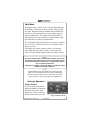
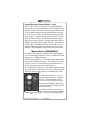
Volume Control
The pilot volume control knob
adjusts the loudness of intercom
and music in the pilot’s headphones only. It has no effect on
selected radio audio levels. The
PMA6000 –Mono Pilot Guide
202-066-0002
Figure 4 Volume Controls
5
copilot volume control adjusts the loudness of the intercom
and music in the copilot headset only. The passenger volume is
factory set at a comfortable level. This is a service adjustment
that can be accessed by the avionics technician. Many general
aviation headsets have a built-in volume control, so volume
can be reduced “locally.”
Adjusting the VOX-Squelch control
The PMA6000 provides adjustable VOX squelch controls for
the pilot and copilot (the copilot's VOX control also adjusts the
passengers VOX squelch). Since the number of microphones
open at any one time is reduced, the amount of background
noise is diminished. This also allows the use of dissimilar
headsets with the same system. The user can adjust the trip
level of the VOX to fit the individual's voice and mic, which
helps eliminate the frustration of clipping the first syllables.
With the engine running, set the VOX control knob by slowly
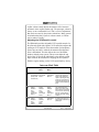
Intercom Mode Table
Mode Pilot Hears Copilot
Hears
Passenger
Hears
Comments
ISO
A/C Radio
Copilot
Pilot Sidetone Passengers
(during radio Music 1
transmission)
Copilot
Passengers
Music 1
This mode allows the pilot to
communicate with the air
traffic control without the
copilot or passengers bothered by the conversations.
Copilot and passengers can
continue to talk and listen to
music
All
Radios
Sidetone
Pilot
Copilot
Passengers
Music 1
Radios
Sidetone
Pilot
Copilot
Passengers
Music 1
Radios
Sidetone
Pilot
Copilot
Passengers
Music 1
This mode allows all on
board to hear radio reception as well as communicate
on the intercom. Music and
intercom is muted during
intercom and radio communications
Crew
Radios
Sidetone
Pilot
Copilot
Music 1
Radios
Sidetone
Copilot
Pilot
Music 1
Passengers
Music 2
A second music source is
automatically enabled for the
passengers
6
202-066-0002
Rev. 3, August 2007
rotating the SQL control knob clockwise until you no longer
hear the engine noise in the headphones. When the microphone is positioned properly near your lips, normal speech levels should open the channel. When you have stopped talking,
there is a delay of about ½ second before the channel closes.
This helps prevent choppy communications.
Some PMA6000 installations may include an intercom Pushto-talk button, located n a yoke or stick. In these installations,
turn the squelch control fully clockwise, and then use the associated ICS P-T-T to talk on the intercom.
Intercom Modes
The center switch is a 3-position mode selector that allows the pilot to tailor the intercom function to best meet the situation.
The description of the intercom mode function is valid only when the unit is either in
the COM 1 or COM 2 position of the Mic Selector switch.
When the unit is in the "Split" mode, only the passengers have
intercom function.
ISO: (Up Position): The pilot is isolated from the intercom and
is connected only to the aircraft radio. He will hear the aircraft
radio reception (and sidetone during radio transmissions). Copilot and passengers will hear the intercom and music on Entertainment 1, but not the aircraft radio receptions or pilot
transmissions.
ALL: (Middle Position): All parties will hear the aircraft radio,
intercom, and music from entertainment input #1. However,
during any intercom communications, the music volume automatically decreases when SoftMute™ is active. The music
volume increases gradually back to the original level after
communications have been completed.
CREW (Down Position): Pilot and copilot are connected on
one intercom channel and have exclusive access to the aircraft
radios. They may also listen to Entertainment 1. Passengers
can continue to communicate with themselves without interPMA6000 –Mono Pilot Guide
202-066-0002
7
rupting the Crew and also may listen to Entertainment 2. Anytime the PMA6000 is in either the COM 1/COM 2, COM 2/COM
1, or TEL/COM 1, ("Split Mode") the pilot and copilot do not
have any intercom function. The passengers will maintain intercommunications.
Soft Mute
Soft Mute must be enabled during installation by jumpering
top connector pins 12 and N. A SPST switch can be installed
between these pins for a pilot selectable mute mode. Without
this connection, music is not muted during intercom activation.
This “Karaoke Mode” prevents the music muting when a singa-long is desired. "Soft Mute" mode only applies to entertainment input #1. Entertainment #2 does not mute.
Entertainment Input
The audio selector panel has provisions for up to two separate
entertainment input devices. Which device is heard is determined by the position of the 3-position mode switch located in
the center of the intercom section of the audio panel. (See Table 1 for overview.)
While in the ISO (Isolate) mode, only the copilot and the four
passengers will hear entertainment device #1. In normal operation, whenever a person speaks, the music will automatically
mute and then will gradually return to the original listening
level when the radio or intercom activity ceases.
When in the ALL mode, all parties will hear the entertainment
input #1. While in the CREW mode, pilot and copilot will hear
entertainment input #1 while the passengers may listen to entertainment input #2.
It is also possible to use only one entertainment input device
for both entertainment inputs (1 and 2). A switch (DPDT)
should be installed between the single entertainment device
and entertainment input #1. This will allow the pilot and copilot decide if they hear entertainment while in the Crew mode.
8
202-066-0002
Rev. 3, August 2007
Internal Recorder System (Option 1, only)
The recorder function is automatic. Pressing the momentary
switch will cause the last message to play (incoming radio and
transmit sidetone). This will be heard in the pilot headset only.
To hear older messages, push the playback button repeatedly
to “back up” the recorder, until the desired message is heard.
The recorder is a continuous loop, and newest ones will overwrite the oldest messages. The IRS has an internal squelch
that prevents storing ‘dead’ air. A radio signal of more than 1
VRMS is needed to trigger the IRS. Therefore, if the IRS does
not seem to be recording, increase the aircraft radio volume
slightly. Holding the button for more than two seconds stops
playback. The next button push will acess the prior message.
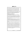
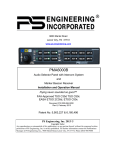
Marker Beacon (PMA6000M-C)
The Marker Beacon Receiver included in the PMA6000M-C
uses visual and audio indicators to alert you when the aircraft
passes over a 75 MHz transmitter.
The Blue lamp, labeled "O," is the Outer Marker lamp and has
an associated 400 Hertz 'dash' tone. The lamp and tone will be
keyed at a rate of two tones/flashes per second when the aircraft is in the range of the Outer Marker Beacon.
The Amber lamp, labeled "M," is the Middle Marker lamp and
is coupled with a 1300 Hertz tone. It is keyed alternately with
short 'dot' and long 'dash' bursts at 95 combinations per minute.
The White lamp, labeled "I” is the Airway/Inner marker and has a 3000 Hertz
'dot' tone. The lamp and tone will be
keyed at a rate of six times per second.
The audio from the Marker Beacon Receiver can be heard by selecting the "M"
push-button switch.
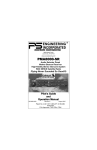
A 3-position switch is used to set the receiver sensitivity and to test the indicator
Figure 5 Marker Bealamps. Use "HIGH" sensitivity initially.
con
PMA6000 –Mono Pilot Guide
202-066-0002
9
This allows you to hear the outer marker beacon about a mile
out. Then select the “LOW” sensitivity to give you a more accurate location of the Outer Marker. The momentary down
switch position is labeled "TEST" and illuminates all three
lamps simultaneously to assure the lamps are in working order.
Early PMA6000M units incorporated a Marker Self Test.
Upon first application of power to the unit, the Marker enters a
self test mode. The flickering blue marker light indicates a test
in process. If the test continues for more than 10 seconds, or
the lamps do not extinguish, return the unit for service.
Warranty and Service
In order for the factory warranty to be valid, the installations in a
certified aircraft must be accomplished by an FAA- certified avionics shop and authorized PS Engineering dealer. An FAA Form 337
must also be accompanied by the warranty card for this warranty to
be in effect. If the unit is being installed in an experimental aircraft
by the owner/builder, a factory-made harness must be installed for
the warranty to be valid.
PS Engineering, Inc. warrants this product to be free from defect in
material and workmanship for a period of one (1) year from the date
of purchase from PS Engineering Dealer. During the twelve (12)
months of this 1-year warranty period, PS Engineering, Inc., at its
option, will send a replacement unit at our expense if the unit should
be determined to be defective after consultation with a factory technician.
This warranty is not transferable. Any implied warranties expire at
the expiration date of this warranty. PS Engineering SHALL NOT
BE LIABLE FOR INCIDENTAL OR CONSEQUENTIAL DAMAGES. This warranty does not cover a defect that has resulted from
improper or unreasonable use or maintenance as determined by us.
This warranty is void if there is any attempt to dissemble this product without factory authorization. This warranty gives you specific
legal rights, and you may also have other rights which may vary
from state to state. Some states do not allow the exclusion of limitation of incidental or consequential damages, so the above limitation
or exclusions may not apply to you.
10
202-066-0002
Rev. 3, August 2007
Factory Service
The unit is covered by a 1-year limited warranty. See warranty
information. Contact PS Engineering, Inc. at (865) 988-9800
or www.ps-engineering.com/support.shtml before you return
the unit. This will allow the service technician to provide any
other suggestions for identifying the problem and recommend
possible solutions.
After discussing the problem with the technician and you obtain a Return Authorization (RMA), ship product to:
Service Department
PS Engineering, Inc.
9800 Martel Rd
Lenoir City, TN 37772
(865) 988-9800 FAX (865) 988-6619
Email: [email protected]
Note: PS Engineering will not be responsible for units shipped
using US Mail. Units that are received without an RMA number, or a detailed description of the problem and a contact
phone number will be refused.
PMA6000 –Mono Pilot Guide
202-066-0002
11
Record
PMA6000 Serial Number: __________________
Date of Purchase: _________________________
Installed by: _____________________________
PS Engineering, Inc. 2007 ©
Copyright Notice
Copyrighted information in this manual is subject to change without notice. PS Engineering
reserves the right to improve or change the products or contents of this manual, without
notification of any person or agency. The contents of this pilot’s guide may be downloaded,
stored and reprinted for personal use provided that this copyright information is included.
Commercial use is strictly prohibited. For further information contact the Publications Manager
at PS Engineering, Inc., 9800 Martel Road, Lenoir City, TN 37772. Phone (865) 988-9800
12
202-066-0002
Rev. 3, August 2007