1
MICROWAVE OVEN
M1774
SERVICE
Manual
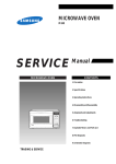
MICROWAVE OVEN
CONTENTS
1. Precaution
2. Specifications
3. Operating Instructions
4. Disassembly and Reassembly
5. Alignment and Adjustments
6. Troubleshooting
7. Exploded Views and Parts List
8. PCB Diagrams
9. Schematic Diagrams
1. Precaution
Follow these special safety precautions. Although the microwave oven is completely safe during ordinary
use, repair work can be extremely hazardous due to possible exposure to microwave radiation, as well as
potentially lethal high voltages and currents.
1-1 Safety precautions (
)
1. All repairs should be done in accordance
with the procedures described in this
manual. This product complies with
Federal Performance Standard 21 CFR
Subchapter J (DHHS).
2. Microwave emission check should be
performed to prior to servicing if the oven is
operative.
3. If the oven operates with the door open :
Instruct the user not to operate the oven and
contact the manufacturer and the center for
devices and radiological health immediatly.
4. Notify the Central Service Center if the
microwave leakage exceeds 5 mW/cm2
5. Check all grounds.
6. Do not power the MWO from a "2-prong"
AC cord. Be sure that all of the built-in
protective devices are replaced. Restore any
missing protective shields.
7. When reinstalling the chassis and its
assemblies, be sure to restore all protective
devices, including: nonmetallic control
knobs and compartment covers.
8. Make sure that there are no cabinet openings
through which people--particularly
children--might insert objects and contact
dangerous voltages. Examples: Lamp hole,
ventilation slots.
9. Inform the manufacturer of any oven found
to have emmission in excess of 5 mW/cm2,
Make repairs to bring the unit into
compliance at no cost to owner and try to
determine cause.
Instruct owner not to use oven until it has
been brought into compliance.
CENTRAL SERVICE CENTER
10. Service technicians should remove their
watches while repairing an MWO.
Samsung Electronics
11. To avoid any possible radiation hazard,
replace parts in accordance with the wiring
diagram. Also, use only the exact
replacements for the following parts:
Primary and secondary interlock switches,
interlock monitor switch.
12. If the fuse is blown by the Interlock Monitor
Switch: Replace all of the following at the
same time: Primary and secondary switches,
as well as the Interlock Monitor Switch. The
correct adjustment of these switches is
described elsewhere in this manual. Make
sure that the fuse has the correct rating for
the particular model being repaired.
13. Design Alteration Warning:
Use exact replacement parts only, i.e.,
only those that are specified in the
drawings and parts lists of this manual.
This is especially important for the
Interlock switches, described above.
Never alter or add to the mechanical or
electrical design of the MWO. Any design
changes or additions will void the
manufacturer's warranty.10.Always unplug
the unit's AC power cord from the AC
power source before attempting to
remove or reinstall any component or
assembly.
14. Never defeat any of the B+ voltage
interlocks. Do not apply AC power to the
unit (or any of its assemblies) unless all
solid-state heat sinks are correctly installed.
15. Some semiconductor ("solid state") devices
are easily damaged by static electricity. Such
components are called Electrostatically
Sensitive Devices (ESDs). Examples include
integrated circuits and field-effect
transistors.
Immediately before handling any
semiconductor components or assemblies,
drain the electrostatic charge from your
body by touching a known earth ground.
16. Always connect a test instrument's ground
lead to the instrument chassis ground before
connecting the positive lead; always remove
the instrument's ground lead last.
1-1
Pretaution
1-2 Special Servicing Precautions (Continued)
17. When checking the continuity of the witches
or transformer, always make sure that the
power is OFF, and one of the lead wires is
disconnected.
18. Components that are critical for safety are
indicated in the circuit diagram by
shading,
or
.
19. Use replacement components that have the
same ratings, especially for flame resistance
and dielectric strength specifications. A
replacement part that does not have the
same safety characteristics as the original
might create shock, fire or other hazards.
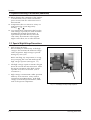
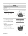
1-3 Special High Voltage Precautions
1. High Voltage Warning
Do not attempt to measureany of the high
voltages--this includes the filament voltage
of the magnetron. High voltage is present
during any cook cycle.
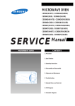
Before touching any components or wiring,
always unplug the oven and discharge the
high voltage capacitor (See Figure 1-1)
2. The high-voltage capacitor remains charged
about 30 seconds after disconnection. Short
the negative terminal of the high-voltage
capacitor to to the oven chassis. (Use a
screwdriver.)
3. High voltage is maintained within specified
limits by close-tolerance, safety-related
components and adjustments. If the high
voltage exceeds the specified limits, check
each of the special components.
Fig. 1-1. Discharging the High Voltage Capacitor
1-2
Samsung Electronics
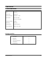
2. Specifications
2-1 Table of Specifications
TIMER
99 MINUTES
POWER SOURCE
230V 50Hz, AC
POWER CONSUMPTION
MICROWAVE : 1,250W
OUTPUT POWER
FROM 100 TO 850W
(IEC-705 TEST PROCEDURE)
OPERATING FREQUENCY
2,450MHz
MAGNETRON
OM75SH(31)
COOLING METHOD
COOLING FAN MOTOR
OUTSIDE DIMENSIONS
489(W) x 275(H) x 370(D)
2-2 Comparison Chart
Samsung Electronics
AUTO REHEAT
O
AUTO COOK
O
POWER LEVEL
O
TIME SETTING AND WEIGHT
O
AUTO DEFROST
O
DEODORIZATION
O
2-1
3. Operating Instructions
3-1 Control Panel
Auto Reheat/Cook Selection
Defrost Selection
Power Level Button
Deodorization Button
Time Setting Selection
Start Button
Cancel Button
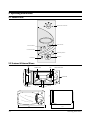
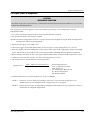
3-2 Features & External Views
Door
Light
Ventilation Holes
Safety Interlock Holes
Control Panel
Glass Plate
Roller Ring
Door Latches
275mm
Coupler
489mm
3-1
370mm
Samsung Electronics
4. Disassembly and Reassembly
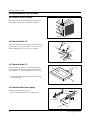
4-1 Replacement of Magnetron, Motor Assembly and Lamp
Remove the magnetron including the shield case, permanent magnet, choke coils and capacitors (all of
which are contained in one assembly).
1. Disconnect all lead wires from the magnetron and lamp.
2. Remove a screw securing the magnetron supporter.
3. Remove the magnetron supporter.
4. Remove the air cover.
5. Remove screws securing the magnetron to the wave guide.
6. Take out the magnetron very carefully.
7. Remove nuts from the back panel.
8. Take out the fan motor.
9. Remove the oven lamp by rotating to pull out from hole of air cover.
NOTE1: When removing the magnetron, make sure that its antenna does not hit any adjacent parts, or it
may be damaged.
NOTE2: When replacing the magnetron, be sure to remount the magnetron gasket in the correct position
and make sure the gasket is in good condition.
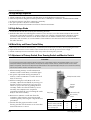
4-2 Replacement of High Voltage Transformer
1. Discharge the high voltage capacitor.
2. Disconnect all the leads.
3. Remove the mounting bolts.
4. Reconnect the leads correctly and firmly.
PRECAUTION
Servicemen should remov their watches whenever
working close to or replacing the magnetron.
PRECAUTION
There exists HIGH VOLTAGE ELECTRICITY with high
current capabilities in the circuits of the HIGH
VOLTAGE TRANSFORMER secondary and filament
terminals. It is extremely dangerous to work on or
near these circuits with the oven energized.
DO NOT measure the voltage in the high voltage
circuit including filament voltage of magnetron.
Samsung Electronics
Screws
H. V. Trans
4-1
Disassembly and Reassembly
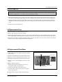
4-3 Replacement of Door Assembly
4-3-1 Removal of Door Assembly
Upper Hinge
Remove hex bolts securing the upper hinge and
lower hinge. Then remove the door assembly.
Screws
Lower Hinge
4-3-2 Removal of Door "C"
Flat Screw Driver
Insert flat screwdriver into the gap between Door
"E" and Door "C" to remove Door "C". Be careful
when handling Door "C" because it is fragile.
Protect Tape
Door "C"
Door "E "
4-3-3 Removal of Door "E"
Following the procedure as shown in the figure,
insert and bend a thin metal plate between Door
"E" and Door "A" until you hear the 'tick' sound.
Door "E"
Sharp Edged
Tool
=> Insertion depth of the thin metal plate should
be 0.5mm or less.
Door "A"
4-3-4 Removal of Key Door & Spring
Remove pin hinge from Door "E"
Detach spring from Door "E" and key door.
Key Door
Hook to hang the key spring
Spring
Door "A"
4-2
Samsung Electronics
Disassembly and Reassembly
4-3-5 Reassembly Test
After replacement of the defective component parts of the door, reassemble it and follow the instructions below for proper
installation and adjustment so as to prevent an excessive microwave leakage.
1. When mounting the door to the oven, be sure to adjust the door parallel to the bottom line of the oven
face plate by moving the upper hinge and lower hinge in the direction necessary for proper alignment.
2. Adjust so that the door has no play between the inner door surface and oven front surface. If the door
assembly is not mounted properly, microwave energy may leak from the space between the door and
oven.
3. Do the microwave leakage test.
4-4 Replacement of Fuse
1. Disconnect the oven from the power source.
2. Remove the 10A fuse in the fuse holder.
3. When replacing the 10A fuse, be sure to use an exact replacement part. If new 10A fuse blows out again
after replacement, check the primary interlock switch, door sensing switch and interlock monitor switch.
4. When the above three switches operate properly, check if any other part such as the control circuit board,
blower motor or high voltage transformer is defective.
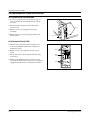
4-5 Replacement of Drive Motor
1. Take out the glass tray, guide roller and coupler
from cavity.
Screw
Drive Motor
2. Turn the oven upside down to replace the drive motor.
3. Remove a screw securing the drive motor cover.
4. Disconnect all the lead wires from the drive motor.
5. Remove screws securing the drive motor to the
cavity.
6. Remove the drive motor.
7. When replacing the drive motor, be sure to
remount it in the correct position.
Drive Motor Cover
Base Plate
8. Connect all the leads to the drive motor.
9. Screw the deive motor cover to the base plate
with a screw driver.
10. Remount the coupler in the correct position.
Samsung Electronics
4-3
Disassembly and Reassembly
4-6 Replacement of Control Circuit Board
4-6-1 Removal of Ass'y Control Box
1. Be sure to ground any static electric charge in
your body and never touch the touch control
circuitry.
2. Disconnect the connectors from the control
circuit board.
SCREW
3. Remove screws securing the control box
assembly.
4. Remove the screw securing the ground tail of
the keyboard.
CONTROL BOX
4-6-2 Remonal of Ass'y P.C.B
1. Pull the lever end of the plastic fastener and
remove the Flexible Printed Circuit(FPC) of
membrane panel.
2. Remove screws securing the control circuit
board.
3. Lift up the control circuit board from the Ass'y
control box.
4. When reconnecting the FPC connector, make
sure that the holes on the connector are properly
engaged with the hooks on the Plastic Fastener.
4-4
screw
FPC
Connector
screw
Samsung Electronics
5. Alignment and Adjustments
PRECAUTION
1. High voltage is present at the high voltage terminals during any cook cycle.
2. It is neither necessary nor advisable to attempt measurement of the high voltage.
3. Before touching any oven components or wiring, always unplug the oven from its power source and discharge the high
voltage capacitor.
5-1 High Voltage Transformer
1. Remove connectors from the transformer terminals
and check continuity.
2. Normal resistance readings are as follows:
Secondary
Filament
Primary
Filament Terminals
Approx. 114W
Approx.0W
Approx.1.47W
(Room temperature = 20ûC)
Secondary
Terminal
Primary
Terminals
5-2 Low Voltage Transformer
1. The low voltage transformer is located on the
control circuit board.
2. Remove the low voltage transformer from the
PCB Ass'y and check continuity.
3. Normal resistor reading is shown in the table.
Terminals
Resistance
1~2(Input)
3~4(Output 2.9V)
5~6(Output13V)
1,000W
3.947W
2.117W
5-3 Magnetron
1. Continuity checks can indicate only an open
filament or a shorted magnetron. To diagnose an
open filament or shorted magnetron :
2. Isolate the magnetron from the circuit by
disconnecting its leads.
3. A continuity check across the magnetron filament
terminals should indicate one ohm or less.
4. A continuity check between each filament terminal
and magnetron case should read open.
Magnetron Antenna
Gasket Plate
Cooling Fins
Samsung Electronics
5-1
Alignment and Adjustments
5-4 High Voltage Capacitor
1. Check continuity of the capacitor with the meter set at the highest resistance scale.
2. Once the capacitor is charged, a normal capacitor shows continuity for a short time, and then indicates 9MW.
3. A shorted capacitor will show continuous continuity.
4. An open capacitor will show constant 9MW.
5. Resistance between each terminal and chassis should read infinite.
5-5 High Voltage Diode
1. Isolate the diode from the circuit by disconnecting its leads.
2. With the ohm-meter set at the highest resistance scale, measure across the diode terminals. Reverse the
meter leads and read the resistance. A meter with 6V, 9V or higher voltage batteries should be used to
check the front-to back resistance of the diode (otherwise an infinite resistance may be read in both
directions). The resistance of a normal diode will be infinite in one direction and several hundred KW in
the other direction.
5-6 Main Relay and Power Control Relay
1. The relays are located on the PCB Ass'y. Isolate them from the main circuit by disconnecting the leads.
2. Operate the microwave oven with a water load in the oven. Set the power level set to high.
3. Check continuity between terminals of the relays after the start pad is pressed.
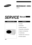
5-7 Adjustment of Primary Switch, Door Sensing Switch and Monitor Switch
Precaution
For continued protection against radiation hazard, replace parts in accordance with the wiring diagram and be sure to use the
correct part number for the following switches: Primary and secondary interlock switches, and the interlock monitor switch
(replace all together). Then follow the adjustment procedures below. After repair and adjustment, be sure to check the continuity
of all interlock switches and the interlock monitor switch.
1. When mounting Primary switch and Interlock
Monitor switch to Latch Body, consult the figure.
2. No specific adjustment during installation of
Primary switch and Monitor switch to the latch
body is necessary.
3. When mounting the Latch Body to the oven
assembly, adjust the Latch Body by moving it so
that the oven door will not have any play in it.
Check for play in the door by pulling the door
assembly. Make sure that the latch keys move
smoothly after adjustment is completed.
Completely tighten the screws holding the Latch
Body to the oven assembly.
4. Reconnect to Monitor switch and check the
continuity of the monitor circuit and all latch
switches again by following the components test
procedures.
5. Confirm that the gap between the switch
housing and the switch actuator is no more than
0.5mm when door is closed.
5-2
Primary Interlock Switch
Interlock
Monitor
Switch
Lever Door(B)
Body Latch
Door Sensing
Switch
Primary switch
Monitor switch (COM-NC)
Monitor switch (COM-NO)
Door Sensing S/W
Door Open
¥
0
¥
¥
Door Closed
0
¥
0
0
Samsung Electronics
Alignment and Adjustments
5-8 Output Power of Magnetron
CAUTION
MICROWAVE RADIATION
PERSONNEL SHOULD NOT ALLOW EXPOSURE TO MICROWAVE RADIATION FROM MICROWAVE GENERATOR OR OTHER PARTS
CONDUCTING MICROWAVE ENERGY.
The output power of the magnetron can be measured by performing a water temperature rise test.
Equipment needed :
* Two 1-liter cylindrical borosilicate glass vessel (Outside diameter 190 mm)
* One glass thermometer with mercury column
NOTE: Check line voltage under load. Low voltage will lower the magnetron output. Make all temperature
and time tests with accurate equipment.
1. Fill the one liter glass vessel with water.
2. Stir water in glass vessel with thermometer, and record glass vessel's temperature ("T1", 10±1ûC).
3. After moving the water into another glass vessel, place it in the center of the cooking tray. Set the oven to high
power and operate for 52 seconds exactly. (3 seconds included as a holding time of magnetron oscillation:)
4. When heating is finished, stir the water again with the thermometer and measure the temperature ("T2").
5. Subtract T1 from T2. This will give you the water temperature rise. (DT)
6. The output power is obtained by the following formula;
Output Power =
4.187 x 1000 x DT+0.55 Wb (T2-TO)
49
49 : Heating Time (sec)
4.187 : Coefficient for Water
1000 : Water (cc)
DT : Temperature Rise (T2-T1)
To : Room Temperature
Wb : Beaker Weisht
7. Normal temperature rise for this model is 9ûC to 11ûC at 'HIGH'.
NOTE 1 : Variations or errors in the test procedure will cause a variance in the temperature rise.
Additional power test should be made if temperature rise is marginal.
NOTE 2 : Output power in watts is computed by multiplying the temperature rise (step E) by a factor of
91 times the of centigrade temperature.
Samsung Electronics
5-3
Alignment and Adjustments
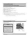
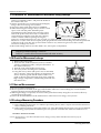
5-9 Procedure for Measurement of Microwave Energy Leakage
1) Pour 275±15cc of 20±5ûC(68±9ûF) water in a beaker
which is graduated to 600cc, and place the beaker in
the center of the oven.
2) Start to operate the oven and measure the leakage by
using a microwave energy survey meter.
3) Set survey meter with dual ranges to 2,450MHz.
4) When measuring the leakage, always use the 2 inch
spacer cone with the probe. Hold the probe
perpendicular to the cabinet door. Place the spacer
cone of the probe on the door and/or cabinet door
seam and move along the seam, the door viewing
window and the exhaust openings moving the
probe in a clockwise direction at a rate of 1 inch/sec. If the leakage testing of the cabinet door seam is
taken near a corner of the door, keep the probe perpendicular to the areas making sure that the probe end
at the base of the cone does not get closer than 2 inches to any metal. If it gets closer than 2 inches,
erroneous readings may result.
5) Measured leakage must be less than 4mW/cm2, after repair or adjustment.
Maximum allowable leakage is 5mW/cm2.
4mW/cm2 is used to allow for measurement and meter accuracy
5-10 Check for Microwave Leakage
1. Remove the outer panel.
2. Pour 275±15cc of 20±5ûC(68±9ûF) water in a beaker
which is graduated to 600cc, and place the beaker in
the center of the oven.
3. Start the oven at the highest power level.
4. Set survey meter dual ranges to 2,450MHz.
5. Using the survey meter and spacer cone as described
above, measure arnear the opening of magnetron, the
surface of the air guide and the surface of the wave
guide as shown in the following photo.( but avoid the
high voltage components.) The neading should be less
than 4mW/cm2.
5-11 Note on Measurement
1) Do not exceed the limited scale.
2) The test probe must be held on the grip of the handle, otherwise a false reading may result when the
operator's hand is between the handle and the probe.
3) When high leakage is suspected, do not move the probe horizontally along the oven surface; this may
cause damage to the probe.
4) Follow the recommendation of the manufacturer of the microwave energy survey meter.
5-12 Leakage Measuring Procedure
5-13-1 Record keeping and notification after measurement
1) After adjustment and repair of a radiarion preventing device, make a repair record for the measured
values, and keep the data.
2) If the radiation leakage is more than 4 mW/cm2 after determining that all parts are in good condition,
functioning properly and the identical parts are replaced as listed in this manual notift that fact to ;
CENTRAL SERVICE CENTER
5-13-2 At least once a year have the microwave energy survey meter checked for accuracy by its
manufacturer.
5-4
Samsung Electronics
6. Troubleshooting
PRECAUTION
1. CHECK GROUNDING BEFORE CHECKING FOR TROUBLE.
2. BE CAREFUL OF THE HIGH VOLTAGE CIRCUIT.
3. DISCHARGE THE HIGH VOLTAGE CAPACITOR.
4. WHEN CHECKING THE CONTINUITY OF THE SWITCHES OR TRANSFORMER, DISCONNECT ONE LEAD WIRE FROM THESE
PARTS AND THEN CHECK CONTINUITY WITHOUT THE POWER SOURCE ON. TO DO OTHERWISE MAY RESULT IN A FALSE
READING OR DAMAGE TO YOUR METER.
5. DO NOT TOUCH ANY PART OF THE CIRCUIT OR THE CONTROL CIRCUIT BOARD, SINCE STATIC DISCHARGE MAY DAMAGE IT.
ALWAYS TOUCH GROUND WHILE WORKING ON IT TO DISCHARGE ANY STATIC CHARGE BUILT UP.
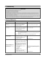
6-1 Electrical Maltunction
SYMPTOM
CAUSE
CORRECTIONS
Oven is dead.
Fuse is OK.
No display and no operation at all.
1. Open or loose lead wire harness
2. Open thermal cutout (Magnetron)
3. Open low voltage transformer
4. Defective Ass'y PCB
Check fan motor when thermal cutout is defective.
No display and no operation at all.
Fuse is blown.
1. Shorted lead wire harness
2. Defective primary latch switch (NOTE 1)
3. Defective monitor switch (NOTE1)
4. Shorted HVCapacitor
5. Shorted HVTransformer (NOTE2)
Check adjustment of primary, interlock monitor,
door sensing switch.
Check Ass'y PCB when LVT is defective.
NOTE 1: All of these switches must be replaced at the same time.
(refer to adjustment instructions)
Check continuity of power relay contacts and if it has continuity, replace power
relay also.
NOTE 2: When HVTransformer is replaced, check diode and magnetron also.
Oven does not accept
key input (Program)
Timer starts countdown but no
microwave oscillation.
(No heat while oven lamp and
fan motor turn on.)
Samsung Electronics
1. Key input is not in-Sequence
2. Open or loose connection of membrane
key pad to Ass'y PCB
3. Shorted or open membrane panel
4. Defective Ass'y PCB
Refer to operation procedure.
1. Off-alignment of latch switches
2. Open or loose connection of high voltage
circuit especially magnetron filament
circuit
NOTE: Large contact resistance will bring
lower magnetron filament voltage and
cause magnetron to lower output and/or
intermittent oscillation.
3. Defective high voltage components
H.V.Transformer
H.V.Capacitor
H.V.Diode, H.V.Fuse
Magnetron
4. Open or loose wiring of power relay
5. Defective primary latch switch
6. Defective power relay or Ass'y PCB
Adjust door and latch switches.
Replace PCB main.
Check high voltage component according to
component test procedure and replace if it is
defective.
Replace PCB main.
6-1
Troubleshooting
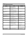
6-1 Electrical Maltunction(continved)
SYMPTOM
CAUSE
CORRECTIONS
Oven lamp and fan motor turn on
1. Misadjustment or loose wiring
of primary latch switch
2. Defective primary latch switch
Adjust door and latch switches.
Oven can program but timer
does not start.
1. Open or loose wiring of secondary
interlock switch
2. Off-alignment of primary interlock
3. Defective secondary interlock S/W
Adjust door and interlock switches.
Microwave output is low;.
Oven takes longer time to
cook food.
1. Decrease in power source voltage.
2. Open or loose wiring of magnetron
filament circuit. (Intermittent oscillation))
3. Aging of magnetron
Consult electrician.
Fan motor turns on when plugged in
Loose wiring of door sensing switch
Check wire of door sensing switch.
Oven does not operate and return
to the plugged in mode.
Defective Ass'y PCB
Replace PCB main.
Loud buzzing noise can be heard.
1. Loose fan and fan motor
2. Loose screws on H.V.Transformer
3. Shorted H.V.Diode
Tighten screws of fan motor.
Tighten screws of H.V.Transformer.
Replace H.V.Diode.
Turntable motor does not rotate.
1. Open or loose wiring of turntable motor.
2. Defective turntable motor.
Replace turntable motor.
Oven stops operation during cooking
1. Open or loose wiring of primary
interlock switch
2. Operation of thermal cutout(Magnetron)
Adjust door and latch switches.
Sparks
1. Metallic ware or cooking dishes
touching on the oven wall.
2. Ceramic ware trimmed with gold or
silver powder also causes sparks.
Inform the customer.
Do not use any type of cookware with
metallic trimming.
Uneven cooking
Uneven intensity of microwave due to
its characteristics.
Wrap thinner parts of the food with
aluminum foil.
Use plastic wrap or cover with a lid.
Stir once or twice while cooking
foods such as soup, cocoa, or milk.
Noise from the turntable motor
when it starts to operate.
Noise may result from the motor.
Replace turntable motor.
6-2
Samsung Electronics
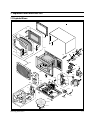
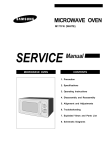
7. Exploded Views and Parts List
7-1 Exploded Views
D5
D8
D9
D4
D3
M28
M1
D6
M27
D7
D10
M26
D1
M2
D2
M3
M24
M4
M7
M5
M6
M25
M10
NC
NO
COM
M29
M21
M15
M22
M9
B2
M8
B1
B3
M23
B4
B2
M14
C11
M17
C12
M16
C6
C2 C3
C7
C1
M19
C9
C10
C4
C8
M20
C13
M18
M11
C5
M12
M13
Samsung Electronics
7-1
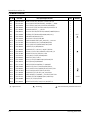
Exploded Views and Parts List
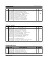
7-2 Main Parts List
Ref. No.
Parts No.
M1
M2
M3
M4
M5
M6
M7
M8
M9
M10
M11
M12
M13
M14
M15
M16
M17
M18
M19
M20
M21
M22
M23
M24
M25
M26
M27
M28
M29
DE70-30116W
DE39-20145A
3601-000448
DE96-00007A
DE71-60467A
DE96-00031A
DE47-20009A
DE03-30029A
DE93-20020A
4713-001004
DE74-20102B
DE92-90436C
DE67-60075A
DE71-60457A
DE26-00014A
DE61-50106A
2501-001016
DE59-40001A
DE91-70061B
DE61-40017A
DE31-10154A
DE80-10003B
DE94-00097A
DE92-40182M
DE71-60450B
DE39-00052A
DE47-20173A
DE64-40008B
DE73-90027A
: Option Parts
7-2
Description/Specification
Q'ty
PANEL-OUTER;SECC,T0.5,W351.7,L1014.7,WHT,M
ASSY POWER CORD;MOONSUNG,-,230V50Hz,-,-,-,M308
FUSE-FERRULE;250V,10A,SLOW-BLOW,CERAMIC,6.3
ASSY NOISE FILTER;SN-3WEA,250V10A,3W INRUSH TC
COVER-BLOWER;PP,-,-,-,-,3RD-0.7
ASSY MOTOR-FAN;SMF-3RDEA,230V50HZ,2400RPM,M1733
THERMOSTAT;PW2N-520PB,160/60,250V/7.5A,H,
MAGNETRON;OM75SH(31)ESS
ASSY BODY LATCH;RE-43B/90B
LAMP-INCANDESCENT;230V,-,40W,ORG,-,-,25x71mm
TRAY-COOKING;GLASS,T5.0,PI288,780G,M745
ASSY-GUIDE ROLLER;MW4370W,D16.5,XAREX
COUPLER;PPS,7G,BRN,M97G45
COVER-AIR;PP,T1.7,W115.5,L150,WHT,3RD-W0
TRANS-H.V;SHV-175EC,230V50HZ,2275V/3.40V,-,DY
BRACKET-HVC;SECC,T0.8,W31,L125.8
C-OIL;950nF,2.1KV,BK,35x54x80,20mm
DIODE-H.V;HVR-1X-32B-12
ASSY-H.V.FUSE;THV060T-0750-H,5KV0.75A,RED
FOOT;PP(A353),BLK,MW5630T
MOTOR-DRIVE;M2HJ49ZR02,ST-16,50/60HZ
BASE-PLATE;SGCC1-Z,T0.8,W340,L550,3RD-0.7
ASSY CONTROL-BOX;230V50HZ,M1774,P-WHT,FISH2
ASSY DOOR;M1774/XEF,P/WHT,3RD-FISH2
COVER-MGT;PP,T2,W110.5,L109,-,28G,3RD-0.7
WIRE HARNESS-A;230V50HZ,-,-,M1774/XEF,3RD FISH2
THERMOSTAT;PW-2N(90/60)30,187Y,250V7.5A,9
DOOR-C;PP,T1.5,BLK,CE745G
FERRITE-CORE;NI-ZN,T13.8,W21.0,L28.0,BNF-14
: Warning
1
1
1
1
1
1
1
1
1
1
1
1
1
1
1
1
1
1
1
2
1
1
1
1
1
1
1
1
1
Remarks
MGT
CAVITY
:Electrostatically Sensitive Devices
Samsung Electronics
Exploded Views and Parts List
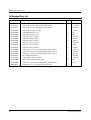
7-3 Door Parts List
Ref. No.
Parts No.
D1
D2
D3
D4
D5
D6
D7
D8
D9
D10
DE64-20116B
DE01-00099A
DE64-40277B
DE64-40278E
DE92-50133C
DE61-70033A
DE64-40264C
DE61-80005A
DE61-80004A
DE92-40196L
Description / Specification
HANDLE-DOOR;ABS,-,-,-,P/WHT,M1774,3RD-FISH2
FILM-DOOR;PET,T0.13,W23,L177.9,-,M759
DOOR-A;ABS(HR-0370),200G,WHT(W9501),M
SCREEN-DOOR;ACRYL,-,-,-,SMOG,M1774,3RD-FISH2
ASSY DOOR-E;MW4593G,-,BLK,3RD-0.7
SPRING-KEY;ES,HSWR10,PI0.6,D6.0,L22.3,BLU
DOOR-KEY;POM(F20-02),5g,BLK,-,2ND HANDL
HINGE-UPPER;SCP1,T2.3,ZN-COATIN,M745
HINGE-LOWER;SCP1,T2.3,ZN-COATING,M745
ASSY DOOR-A;M1774/XEF,P/WHT,3RD-FISH2
Q'ty
Remarks
1
1
1
1
1
1
1
1
1
1
7-4 Control Parts List
Ref. No.
Parts No.
C1
C2
C4
C5
C6
C7
C8
C9
C10
C11
C12
C13
DE71-00005A
DE66-00013A
DE67-00003A
DE72-00009A
DE66-00014A
DE66-00016A
DE66-20182J
DE64-10127B
DE66-00015A
DE97-00054A
DE94-00157A
DE71-60378A
Description/Specification
COVER-PANEL;ABS(HR0370),-,-,-,P-WHT,M1774/XEF
BUTTON-SELECT(A);ABS(HR0370),-,-,P/WHT
WINDOW-DISPLAY;SAN,-,-,-,SMOG,M1774
CONTROL-PANEL;M1774,-,-,-,-,P-WHT,FISH2
BUTTON-SELECT(B);ABS(HR0370),-,-,P-WHT,M1774/XEF
BUTTON-CANCEL;ABS(HR0370),-,-,P/WHT
BUTTON-START;ABS,-,2G,P/WHT,M1774,3RD FISH2
KNOB-COVER;ABS(HR0370U),-,WHT(W9501),-,CE
BUTTON-CLOCK;ABS(HR0370),-,-,P/WHT
ASSY PCB-MAIN;RC-F207-00,M1774
ASSY CONTROL-PANEL;230V50HZ,M1774/XEF,P/WHT,3RD-FISH2
COVER-LAMP;POM,T2,W19.4,L27,3G,NTR,RE-446
Q'ty
Remarks
1
1
1
1
1
1
1
1
1
1
1
1
7-5 Body Latch Parts List
Ref. No.
B1
B2
B3
B4
Parts No.
DE66-40021A
3405-000178
3405-000175
DE66-90054A
Samsung Electronics
Description / Specification
LATCH-BODY;POM(F20-02),50G,RE-330
SWITCH-MICRO;250V,15A,200gf,SPST-NO
SWITCH-MICRO;250V,15A,200gf,SPST-NO
LEVER-SWITCH;POM(F20-02),15G,NTR,RE-330
Q'ty
Remarks
1
2
1
1
7-3
Exploded Views and Parts List
7-6 Standard Parts List
7-4
Parts No.
Description / Specification
Q'ty
Remarks
DE60-10012A
DE60-10012A
DE60-10012A
DE60-10063A
DE60-10080A
DE60-10080A
DE60-10082H
DE60-10082H
DE60-10082H
DE60-10082H
DE60-10082H
DE60-10082H
DE60-10098A
DE60-10098A
DE60-10098A
DE60-30016A
DE60-10069A
DE60-10088A
DE60-10098A
DE60-10012A
SCREW-TAP TITE;TH,+,3,M4,L10,SWR10,ZPC2,TOOTH
SCREW-TAP TITE;TH,+,3,M4,L10,SWR10,ZPC2,TOOTH
SCREW-TAP TITE;TH,+,3,M4,L10,SWR10,ZPC2,TOOTH
SCREW-TAP TH;TH,M4,L12,FEFN
SCREW-WASHER;M5,L12,2S
SCREW-WASHER;M5,L12,2S
SCREW-A;2S-4X12,TOOTHED
SCREW-A;2S-4X12,TOOTHED
SCREW-A;2S-4X12,TOOTHED
SCREW-A;2S-4X12,TOOTHED
SCREW-A;2S-4X12,TOOTHED
SCREW-A;2S-4X12,TOOTHED
SCREW-ASSY TAP TITE;PH,TC,M4X8,SWRCH18A,ZPC2,GLD,W
SCREW-ASSY TAP TITE;PH,TC,M4X8,SWRCH18A,ZPC2,GLD,W
SCREW-ASSY TAP TITE;PH,TC,M4X8,SWRCH18A,ZPC2,GLD,W
NUT-FLANGE;M4,MSWR10
SCREW-TAP TH;TH,M4,L10,FRFZY
SCREW-TAP PH;PH,M3,L8,FEFZY,PLAIN
SCREW-ASSY TAP TITE;PH,TC,M4X8,SWRCH18A,ZPC2,GLD,W
SCREW-TAP TITE;TH,+,3,M4,L10,SWR10,ZPC2,TOOTH
1
1
1
1
4
4
1
2
4
1
2
4
1
2
2
2
2
10
1
1
N/P EARTH
P/C EARTH
PCB EARTH
O/PANEL
HVT
MGT
AIR/COVER
B/LATCH
B/PLATE
C/BLOWER
C/BOX
O/PANEL
CAVITY TCO
D/MOTOR
MGT TCO
F-MOTOR
SCR/DOOR
PCB
H.V.D
-
Samsung Electronics
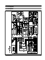
8. P.C.B Diagrams
8-1 P.C.B Diagrams
Samsung Electronics
8-1
P.C.B Diagrams
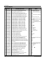
8-2 P.C.B Parts List
No.
Parts No.
P1
P1
P2
P3
P4
P5
P6
P7
P8
P9
P9
P10
P10
P11
P11
P12
P13
P14
P15
P16
P17
P18
P19
P20
P21
P22
P23
P24
P25
P26
P27
P28
P28
P30
P31
P32
P33
P34
P34
P34
P35
P36
P37
P38
P39
P40
P41
P42
P43
P44
P45
P46
0401-001025
0401-001025
0402-001103
0403-000355
0501-000388
0504-001014
0504-001015
0504-001044
1203-000460
2001-000032
2001-000032
2001-000290
2001-000290
2001-000429
2001-000429
2001-000435
2001-000515
2001-000577
2001-000613
2001-000780
2001-000786
2202-000127
2202-000173
2202-000780
2401-000151
2401-000244
2401-000466
2401-000914
2401-002075
2401-002598
2802-000161
3404-001022
3404-001022
3711-000940
3711-004142
3711-004143
DE13-20009A
DE39-60001A
DE39-60001A
DE39-60001A
3501-001050
3501-001062
3601-001126
3708-001315
DE07-20126A
DE09-00035A
DE13-20013A
DE26-20146A
DE30-20016A
DE34-20071A
DE39-40723A
DE47-40024A
8-2
Description / Specification
DIODE-SWITCHING;1N4148M,50V,450mA,DO-34,TP
DIODE-SWITCHING;1N4148M,50V,450mA,DO-34,TP
DIODE-RECTIFIER;1T4,400V,1A,TS-1,TP
DIODE-ZENER;UZ5.1BSB,5.1V,4.97-5.18V,500mW
TR-SMALL SIGNAL;KSC815,NPN,400mW,TO-92,BK,120TR-DIGITAL;KSR1005,NPN,300MW,4.7K/10K,TO-92,TP
TR-DIGITAL;KSR1005,PNP,300MW,4.7K/10K,TO-92,TP
TR-DIGITAL;KRA226M,PNP,400MW,2.2K/10K,TO-92M,TP
IC-POSI.FIXED REG.;78L05,TO-92,3P,-,PLASTIC,4.8/5
R-CARBON;180OHM,5%,1/4W,AA,TP,2.4X6.4MM
R-CARBON;180OHM,5%,1/4W,AA,TP,2.4X6.4MM
R-CARBON;10KOHM,5%,1/8W,AA,TP,1.8X3.2MM
R-CARBON;10KOHM,5%,1/8W,AA,TP,1.8X3.2MM
R-CARBON;1KOHM,5%,1/8W,AA,TP,1.8X3.2MM
R-CARBON;1KOHM,5%,1/8W,AA,TP,1.8X3.2MM
R-CARBON;1MOHM,5%,1/8W,AA,TP,1.8X3.2MM
R-CARBON;220OHM,5%,1/8W,AA,TP,1.8X3.2MM
R-CARBON;2KOHM,5%,1/8W,AA,TP,1.8X3.2MM
R-CARBON;3.9KOHM,5%,1/8W,AA,TP,1.8X3.2MM
R-CARBON;470OHM,5%,1/8W,AA,TP,1.8X3.2MM
R-CARBON;47KOHM,5%,1/8W,AA,TP,1.8X3.2MM
C-CERAMIC,MLC-AXIAL;10nF,+80-20%,25V,Y5V,TP,-,7.5
C-CERAMIC,MLC-AXIAL;1nF,10%,50V,Y5P,TP,1.9x3.5
C-CERAMIC,MLC-AXIAL;100nF,+80-20%,50V,Y5V,TP,3.5x1
C-AL;1000uF,20%,25V,GP,TP,12.5x20,5
C-AL;100uF,20%,10V,GP,TP,6.3x7,5
C-AL;10uF,20%,35V,GP,TP,5x7,5
C-AL;22uF,20%,16V,GP,TP,5x11,5
C-AL;4.7uF,20%,50V,GP,TP,5x11,5
C-AL;220uF,20%,50V,GP,TP,10x16,5
RESONATOR-CERAMIC;4MHz,0.5%,TP,10.0x5.0x7.5mm
SWITCH-TACT;15V,20mA,130±40gf,6x6x5mm,SPS
SWITCH-TACT;15V,20mA,130±40gf,6x6x5mm,SPS
CONNECTOR-HEADER;BOX,4P,1R,2.5mm,STRAIGHT,SN
CONNECTOR-HEADER;BOX,3P/5P,1R,5mm/2.5mm,STRAIGH
CONNECTOR-HEADER,BOX,2P/3P,1R,5mm/2.5mm,STRAIGH
IC,KA7533,DIP
WIRE-SO COPPER,PI0.6,SN,T,52MM,TAPING_WIRE
WIRE-SO COPPER;PI0.6,SN,T,52MM,TAPING_WIRE
WIRE-SO COPPER;PI0.6,SN,T,52MM,TAPING_WIRE
RELAY-MINIATURE;24VDC,200mW,5A,1FormA,10mS,5mS
RELAY-POWER;24VDC,523.2mW,16A,1FormA,15mS,
FUSE-FERRULE;250V,1.6A,QUICK-ACTING,CERAMIC
CONNECTOR-FPC/FC/PIC;12P,2mm,STRAIGHT,SN
LED DISPLAY;LTC-4638G,GRN,12,30,48.2X22.38
IC-MCU;HD404316-D83S,M1974,4BIT
IC-DRIVE;KA2657,DIP
TRANS-L.V;SLV-745EN,230V,50HZ,AC17/7V
BUZZER;CBE2220BA,STICK
SWITCH-ROTARY;DC10V,1MA,SH,PA-1005A-003-000
WIRE HARNESS;DC35V,C-959G,80mm,12PIN
HOLDER-FUSE;FH-51H,7.5A
Q'ty
Remarks
5
5
6
1
1
6
1
5
1
6
2
6
5
6
2
1
1
2
2
1
3
2
3
4
1
1
1
2
1
1
1
5
2
1
1
1
1
6
6
3
2
1
1
1
1
1
1
1
1
1
1
1
D007,D008,D010,D011,D012
D013,D014,D015,D016,D017
D001,D002,D003,D004,D005,D009
ZD01
TR04
TR02,TR03,TR05,TR07,TR08,TR09
TR06
TR10,TR11,TR12,TR13,TR14
RG01
R017,R018,R019,R020,R021,R022
R023,R024
R005,R006,R007,R010,R013,R016
R031,R032,R033,R036,R037
R003,R004,R008,R028,R029,R030
R034,R035
R011
R015
R001,R002
R012,R039
R009
R025,R026,R027
C012,C013
C014,C015,C016
C004,C006,C007,C010
C001
C003
C011
C005,C008
C009
C002
XTL1
SW01,SW02,SW03,SW04,SW05
SW06,SW07
CN04
CN02
CN03
IC02
J001,J002,J003,J004,J005,J006
J007,J008,J009,J010,J011,J012
J013,J014,J015
RY01,RY02
RY03
FUS1
CN05
DSP1
IC01
IC03
LVT1
BUZ1
ECD1
WIR1
FUS1
Samsung Electronics
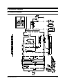
9. Schematic Diagrams
9-1 Schematic Diagrams
Samsung Electronics
9-1