1
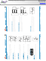
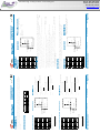
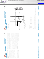
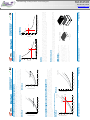
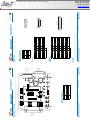
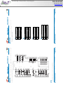
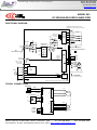
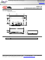
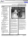
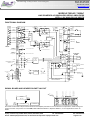
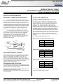
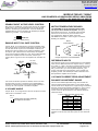
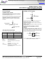
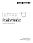
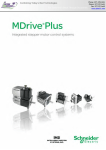
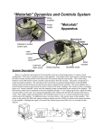
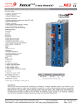
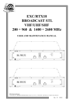
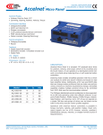
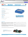
Combining Today’s Best Technologies
For Tomorrow’s Break Through Discoveries
Phone: 877-478-3241
Phone: 877-IP-Tech1
Fax: 877-IP-Tech2
www.iptech1.com
Analog Inputs
Analog Outputs
Digital Inputs
Actual Size
Digital Outputs
Feedback
Model
Vdc
Ic
Ip
BTM-055-20
12~55
10
20
BTM-090-10
12~90
5
10
Dimensions
DESCRIPTION
Bantam
torque control of DC brush or brushless motors. It operates as a
stand-alone driver taking a ±10V input from an external controller.
Mounting to a PC board with solderless connectors facilitates lowcost, multi-axis designs.
regenerative energy dissipator circuit and another for motor brake
control.
The Amp Enable input interfaces to active LO signals up to 24 Vdc.
Another digital input switches the current-loop gain from a high to
low for load inductance compensation. Forward and Reverse Enable
inputs are provided for limit switches.
outputs.
motors. For driving DC brush motors, these inputs are left
Protections include I2T current limiting for peak and continuous
current as well as peak time. Short circuits between outputs or to
are two other digital outputs one of which can activate an external
DEVELOPMENT KIT
A Development Kit is available that provides
mounting and easy connectivity for the
Bantam.
Copley Controls, 20 Dan Road, Canton, MA 02021, USA
Web: www.copleycontrols.com
Tel: 781-828-8090
Fax: 781-828-6547
Page 1 of 18
Combining Today’s Best Technologies
For Tomorrow’s Break Through Discoveries
Phone: 877-478-3241
Phone: 877-IP-Tech1
Fax: 877-IP-Tech2
www.iptech1.com
Combining Today’s Best Technologies
For Tomorrow’s Break Through Discoveries
Phone: 877-478-3241
Phone: 877-IP-Tech1
Fax: 877-IP-Tech2
www.iptech1.com
Combining Today’s Best Technologies
For Tomorrow’s Break Through Discoveries
Phone: 877-478-3241
Phone: 877-IP-Tech1
Fax: 877-IP-Tech2
www.iptech1.com
Combining Today’s Best Technologies
For Tomorrow’s Break Through Discoveries
Phone: 877-478-3241
Phone: 877-IP-Tech1
Fax: 877-IP-Tech2
www.iptech1.com
Combining Today’s Best Technologies
For Tomorrow’s Break Through Discoveries
Phone: 877-478-3241
Phone: 877-IP-Tech1
Fax: 877-IP-Tech2
www.iptech1.com
Combining Today’s Best Technologies
For Tomorrow’s Break Through Discoveries
Phone: 877-478-3241
Phone: 877-IP-Tech1
Fax: 877-IP-Tech2
www.iptech1.com
Rth (C/W)
Rth (C/W)
Amplifier temperature (C)
Power Dissipation (W)
Power Dissipation (W)
Amplifier temperature (C)
Combining Today’s Best Technologies
For Tomorrow’s Break Through Discoveries
Phone: 877-478-3241
Phone: 877-IP-Tech1
Fax: 877-IP-Tech2
www.iptech1.com
Combining Today’s Best Technologies
For Tomorrow’s Break Through Discoveries
Phone: 877-478-3241
Phone: 877-IP-Tech1
Fax: 877-IP-Tech2
www.iptech1.com
Combining Today’s Best Technologies
For Tomorrow’s Break Through Discoveries
Phone: 877-478-3241
Phone: 877-IP-Tech1
Fax: 877-IP-Tech2
www.iptech1.com
MASTER ORDERING GUIDE
BTM-055-20
BTM-090-10
BDK-090-01
Development kit
BDK-CK
Connector Kit for Development Kit
Example: Order 1 BTM-055-20 current amplifier and development kit:
Qty
Item
Remarks
1
1
1
BTM-055-20
BDK-090-01
BDK-CK
current amplifier
Development Kit for Bantam amplifier
Connector Kit for Development Kit
ACCESSORIES
ORDER NUMBER
Qty
Ref
DESCRIPTION
1
1
1
Norcomp 979-015-020R121
1
1
Norcomp 979-025-020R121
1
1
4
Rev 3.09_fr 01/28/2011
Copley Controls, 20 Dan Road, Canton, MA 02021, USA
Web: www.copleycontrols.com
Tel: 781-828-8090
Fax: 781-828-6547
Page 18 of 18
Combining Today’s Best Technologies
For Tomorrow’s Break Through Discoveries
Phone: 877-478-3241
Phone: 877-IP-Tech1
Fax: 877-IP-Tech2
www.iptech1.com
MODEL 503
DC BRUSHLESS SERVO AMPLIFIER
50 Volts output at 10A Peak, 5A Continuous
FEATURES
Complete torque ( current )
mode functional block
Drives motor with
60 or 120 Halls
Single supply voltage
18-55VDC
5A continuous, 10A peak
more than double the power
output of servo chip sets
Fault protected
Short-circuits from output to
output, output to ground
Over/under voltage
Over temperature
Self-reset or latch-off
2.5kHz bandwidth
Wide load inductance range
0.2 to 40 mH.
+5, +15V Hall power
Separate continuous, peak,
and peak-time current limits
Surface mount technology
APPLICATIONS
X-Y stages
Robotics
Automated assembly
machinery
Component insertion
machines
THE OEM ADVANTAGE
NO POTS: Internal
component header
configures amplifier for
applications
Conservative design for high
MTBF
Low cost solution for small
brushless motors to 1/3 HP
Model 503
PRODUCT DESCRIPTION
Model 503 is a complete pwm
servoamplifier for applications using
DC brushless motors in torque
( current ) mode. It provides six-step
commutation of three-phase DC
brushless motors using 60° or 120°
Hall sensors on the motor, and
provides a full complement of features
for motor control. These include
remote inhibit/enable, directional
enable inputs for connection to limit
switches, and protection for both motor
and amplifier.
The /Enable input has selectable
active level ( +5V or gnd ) to interface
with most control cards.
/Pos and /Neg enable inputs use failsafe (ground to enable) logic.
Power delivery is four-quadrant for
bi-directional acceleration and
deceleration of motors.
Model 503 features 500W peak power
output in a compact package using
surface mount technology.
An internal header socket holds
components which configure the
various gain and current limit settings
to customize the 503 for different loads
and applications.
Separate peak and continuous current
limits allow high acceleration without
sacrificing protection against
continuous overloads. Peak current
time limit is settable to match amplifier
to motor thermal limits.
Header components permit
compensation over a wide range of
load inductances to maximize
bandwidth with different motors.
Package design places all connectors
along one edge for easy connection
and adjustment while minimizing
footprint inside enclosures.
High quality components and
conservative ratings insure long
service life and high reliability in
industrial installations.
A differential amplifier buffers the
reference voltage input to reject
common-mode noise resulting from
potential differences between
controller and amplifier grounds.
Output short circuits and heatplate
overtemperature cause the amplifier to
latch into shutdown. Grounding the
reset input will enable an auto-reset
from such conditions when this feature
is desired.
Copley Controls, 20 Dan Road, Canton, MA 02021, USA
Tel: 781-828-8090
Fax: 781-828-6547
Tech Support: E-mail: [email protected], Web: http://www.copleycontrols.com
Combining Today’s Best Technologies
For Tomorrow’s Break Through Discoveries
Phone: 877-478-3241
Phone: 877-IP-Tech1
Fax: 877-IP-Tech2
www.iptech1.com
MODEL 503
DC BRUSHLESS SERVO AMPLIFIER
FUNCTIONAL DIAGRAM
MOMENTARY SWITCH RESETS FAULT
WIRE RESET TO GROUND FOR SELF-RESET
3
SHORT/O.T.
POWER FAULT
NORMAL
CH2
1.5 NF
RH1
499K
LED'S
R
R
G
+5V
8
STATUS
&
CONTROL
LOGIC
4
5
6
1nF
7
REF AMP
REF(-) 10
REF(+) 11
10K
10K
RH7
CURRENT LIMIT
SECTION
100K
-
470 PF 2.2 MEG
-
+
RH6
10K
RH3
PEAK
10K
J2 SIGNAL CONNECTOR
RH4
PEAK
TIME
1nF
1
RESET
+NORMAL
NEG ENABLE
POS ENABLE
ENABLE
ENABLE POL
GND
100 PF
J2 SIGNAL CONNECTOR
+
50K
CURRENT
ERROR
AMP
J1 MOTOR & POWER CONNECTOR
RH5
CONT
Gv = 1
CURRENT 9
MONITOR
1K
OUTPUT
CURRENT
SENSE
33NF
+/-5V AT
+/-10A
V
HALLS
W
+5
+15
GND
1
2
3
4
Gv = +HV
10
OPEN = 120 DEG.
GND = 60 DEG.
HALLSELECT 2
U
PWM
STAGE
MOSFET
"H"
BRIDGE
5
U
MOTOR
V
W
+HV
GND
17
HALL
LOGIC
16
15
+HV
GROUND CASE FOR SHIELDING
+5
14
+15
13
DC / DC
CONVERTER
CASE GROUND
NOT CONNECTED
TO CIRCUIT GROUND
-15
18
POWER GROUND AND SIGNAL GROUNDS ARE COMMON
TYPICAL CONNECTIONS
CONTROLLER
REF(-)
10
11
SIG GND
J2
12
J1
DC POWER SUPPLY
V
2
-
5
+
4
MOTOR
U
1
GND
AC
W
3
REF(+)
J1
AC
+HV
13
J2
14
15
16
SIG GND
1
/NEG ENAB
4
/POS ENAB
5
/ENABLE
6
17
18
J2
+15 V
+5 V
Vcc
W
V
U
GND
HALL
SENSORS
Copley Controls, 20 Dan Road, Canton, MA 02021, USA
Tel: 781-828-8090
Fax: 781-828-6547
Tech Support: E-mail: [email protected], Web: http://www.copleycontrols.com
Combining Today’s Best Technologies
For Tomorrow’s Break Through Discoveries
Phone: 877-478-3241
Phone: 877-IP-Tech1
Fax: 877-IP-Tech2
www.iptech1.com
MODEL 503
DC BRUSHLESS SERVO AMPLIFIER
APPLICATION INFORMATION (CONT'D)
COMPONENT HEADER
HEADER LOCATION
WARNING!
DISCONNECT POWER WHEN CHANGING HEADER
COMPONENTS. REPLACE COVER BEFORE APPLYING
POWER TO PREVENT CONTACT WITH LIVE PARTS.
( COVER REMOVED )
RH1
J1
LOAD INDUCTANCE SETTING
CH2
J2
RH3
PEAK CURRENT LIMIT
RH4
PEAK CURRENT TIME LIMIT
RH5
CONTINUOUS CURRENT LIMIT
RH6
REFERENCE GAIN SETTING
RH7
LEDS
NOTE: Components in dotted lines are
not installed at factory
INPUT TO OUTPUT GAIN SETTING ( RH6, RH7 )
G AIN
10
(A)
=
(V) RH 6
(k
(k
)
)
Note 1
Example: Standard value of RH6 is 10k , thus G = 1 A/V
LOAD INDUCTANCE SETTING (RH1 & CH2) Note 2
Load (mH)
0.2
1
3
10
33
40
RH1
49.9 k
150 k
499 k
499 k
499 k
499 k
CH2
1.5 nF
1.5 nF
1.5 nF *
3.3 nF
6.8 nF
10 nF
PEAK CURRENT LIMIT (RH3) Note 3
Ipeak (A)
10
8
6
4
2
RH3 ( )
open *
12k
4.7k
2k
750
PEAK CURRENT TIME-LIMIT (RH4) Note 4
Tpeak (s)
0.5
0.4
0.2
0.1
RH4 ( )
open *
10 M
3.3 M
1M
Times shown are for 10A step from 0A
Notes:
* Standard values installed at factory are shown in
italics.
1. RH6 & RH7 should be 1% resistors of same value.
2. Bandwidth and values of RH1, CH2 are affected by supply
voltage and load inductance. Final selection should be
based on customer tests using actual motor at nominal
supply voltage.
3. Peak current setting should always be greater than
continuous current setting.
4. Peak times will double when current changes polarity.
Peak times decrease as continuous current increases.
CONTINUOUS CURRENT LIMIT (RH5)
Icont (A)
5
4
3
2
1
RH5 ( )
open *
20k
8.2k
3.9k
1.5k
Copley Controls, 20 Dan Road, Canton, MA 02021, USA
Tel: 781-828-8090
Fax: 781-828-6547
Tech Support: E-mail: [email protected], Web: http://www.copleycontrols.com
Combining Today’s Best Technologies
For Tomorrow’s Break Through Discoveries
Phone: 877-478-3241
Phone: 877-IP-Tech1
Fax: 877-IP-Tech2
www.iptech1.com
MODEL 503
DC BRUSHLESS SERVO AMPLIFIER
TECHNICAL SPECIFICATIONS
Typical specifications @ 25 C ambient, +HV = +55VDC. Load = 200µH. in series with 1 ohm unless otherwise specified.
OUTPUT POWER
Peak power
Unidirectional
After direction change
Continuous power
10A @ 50V for 0.5 second, 500W
±10A @ 50V for 1 second, 500W
±5A @ 50V, 250W
OUTPUT VOLTAGE
Vout = 0.97HV -(0.4)(Iout)
MAXIMUM CONTINUOUS OUTPUT CURRENT
Convection cooled, no conductive cooling
±2A @ 35°C ambient
Mounted on narrow edge, on steel plate, fan-cooled 400 ft/min
±5A @ 55°C
LOAD INDUCTANCE
Selectable with components on header socket
200 µH to 40mH (Nominal, for higher inductances consult factory)
BANDWIDTH
Small signal
-3dB @ 2.5kHz with 200µH load
Note: actual bandwidth will depend on supply voltage, load inductance, and header component selection
PWM SWITCHING FREQUENCY
25kHz
ANALOG INPUT CHARACTERISTICS
Reference
Differential, 20K between inputs with standard header values
GAINS
Input differential amplifier
X1 as delivered. Adjustable via header components RH6, RH7
PWM transconductance stage
1 A/V ( output vs. input to current limit stage )
OFFSET
Output offset current ( 0 V at inputs )
20 mA max. ( 0.2% of full-scale )
Input offset voltage
20 mV max ( for 0 output current, RH6,7 = 10k )
LOGIC INPUTS
Logic threshold voltage
HI: 2.5V , LO: 1.0V, +5V Max on all logic inputs
/Enable
LO enables amplifier (/Enable Pol open) , HI inhibits; 50 ms turn-on delay
/POS enable, /NEG enable
LO enables positive and negative output currents, HI inhibits
/Reset
LO resets latching fault condition, ground for self-reset every 50 ms.
/Enable Pol (Enable Polarity)
LO reverses logic of /Enable input only (HI enables unit, LO inhibits)
LOGIC OUTPUTS
+Normal
HI when unit operating normally, LO if overtemp, output short, disabled, or power supply (+HV) out of tolerance
HI output voltage = 2.4V min at -3.2 mA max., LO output voltage = 0.5V max at 2 mA max.
Note: Do not connect +Normal output to devices that operate > +5V
INDICATORS (LED's)
Normal (green)
ON = Amplifier enabled, no shorts or overtemp, power within limits
Power fault (red)
ON = Power fault: +HV <18V OR +HV > 55V
Short/Overtemp (red)
ON = Output short-circuit or over-temperature condition
CURRENT MONITOR OUTPUT
5V @ 10A (2A/volt), 10k , 3.3nF R-C filter
DC POWER OUTPUTS
+5VDC
30mA (Includes power for Hall sensors)
+15VDC
10mA
Total power from all outputs not to exceed 200mW.
PROTECTION
Output short circuit (output to output, output to ground)
Overtemperature
Power supply voltage too low (Undervoltage)
Power supply voltage too high (Overvoltage)
Latches unit OFF (self-reset if /RESET input grounded)
Shutdown at 70°C on heatplate (Latches unit OFF)
Shutdown at +HV < 18VDC (operation resumes when power >18VDC)
Shutdown at +HV > 55VDC (operation resumes when power <55VDC)
POWER REQUIREMENTS
DC power (+HV)
Minimum power consumption
Power dissipation at 5A output, 55VDC supply
Power dissipation at 10A output, 55VDC supply
+18-55 VDC @ 10A peak.
2.5 W
10W
40W
THERMAL REQUIREMENTS
Storage temperature range
Operating temperature range
-30 to +85°C
0 to 70°C baseplate temperature
MECHANICAL
Size
Weight
3.27 x 4.75 x 1.28 in. (83 x 121 x 33mm)
0.52 lb (0.24 kg.)
Power & motor
Signal & Halls
Weidmuller: BL-125946; Phoenix: MSTB 2.5/5-ST-5.08
Molex: 22-01-3167 housing with 08-50-0114 pins
CONNECTORS
Copley Controls, 20 Dan Road, Canton, MA 02021, USA
Tel: 781-828-8090
Fax: 781-828-6547
Tech Support: E-mail: [email protected], Web: http://www.copleycontrols.com
Combining Today’s Best Technologies
For Tomorrow’s Break Through Discoveries
Phone: 877-478-3241
Phone: 877-IP-Tech1
Fax: 877-IP-Tech2
www.iptech1.com
MODEL 503
DC BRUSHLESS SERVO AMPLIFIER
APPLICATION INFORMATION
SETUP BASICS
To use the model 503 set up the
internal header with the components
that configure the transconductance,
current limits, and load inductance.
Current-limits and load inductance set
up the amplifier for your particular
motor, and the transconductance
defines the amplifiers overall response
in amps/volt that is required by your
system.
1. Set RH1 and CH2 for motor load
inductance (see following section).
2. Set RH3, 4, & 5 if current limits
below standard values is required.
3. Ground the /Enable (/Enable Pol
open), /Pos Enable, and /Neg
Enable inputs to signal ground.
4. Connect the motor Hall sensors to
J2 based on the manufacturers
suggested signal names. Note that
different manufacturers may use
A-B-C, R-S-T, or U-V-W to name
their Halls. Use the required Hall
supply voltage (+5 or +15V). Note
that there is a 30 mA limit at +5V.
Encoders that put-out Hall signals
typically consume 200-300 mA, so if
these are used, then they must be
powered from an external power
supply.
5. Connect J1-4,5 to a transformerisolated source of DC power,
+18-55V. Ground the amplifier and
power supply with an additional wire
from J1-5 to a central ground point.
6. With the motor windings
disconnected, apply power and
slowly rotate the motor shaft.
Observe the Normal (green) led. If
the lamp blinks while turning then
the 60/120° setting is incorrect. If J22 is open, then ground it and repeat
the test. In order to insure proper
operation, the correct Hall phasing of
60° or 120° must be made.
6.Turn off the amplifier and connect
the motor leads to J1-1,2,3 in U-V-W
order. Power up the unit. Apply a
sinusoidal reference signal of about
1 Hz. and 1Vrms between
Ref(+) and Ref(-), J2-10,11.
7. Observe the operation of the motor
as the current monitor signal passes
through zero. When phasing is correct
the speed will be smooth at zero
crossing and at low speeds. If it is not,
then power-down and re-connect the
motor.
COMPONENT HEADER
SETTINGS
Use the tables provided to select
values for your load and system. We
recommend that you use these values
as starting points, adjusting them later
based on tests of the amplifier in your
application.
LOAD INDUCTANCE (RH1,CH2)
Maximizes the bandwidth with your
motor and supply voltage. First replace
CH2 with a jumper (short). Adjust the
value of RH1 using a step of 1A or less
so as not to experience large signal
slew-rate limiting. Select RH1 for the
best transient response ( lowest
risetime with minimal overshoot). Once
RH1 has been set. choose the
smallest value of CH2 that does not
cause additional overshoot or
degradation of the step response.
TRANSCONDUCTANCE (RH6,7)
The transconductance of the 503 is the
ratio of output current to input voltage.
It is equal to 10k /RH6 (Amps/Volt).
RH6,and RH7 should be the same
value and should be 1% tolerance
metal film type for good common-mode
noise rejection.
CURRENT LIMITS (RH3, 4, & 5)
The amplifier operates at the 5A
continuous, 10A peak limits as
delivered. To reduce the limit settings,
choose values from the tables as
starting points, and test with your
motor to determine final values. Limit
action can be seen on current monitor
when output current no longer changes
in response to input signals. Separate
control over peak, continuous, and
peak time limits provides protection for
motors, while permitting higher
currents for acceleration.
There are six possible ways to connect
the motor windings, and only one of
these will result in proper motor
operation. The six combinations are
listed in the table below. Incorrect
phasing will result in erratic operation,
and the motor may not rotate. When
the correct combination is found,
record your settings.
#1
#2
#3
#4
#5
#6
J1-1
U
V
W
U
W
V
J1-2
V
W
U
W
V
U
J1-3
W
U
V
V
U
W
GROUNDING & POWER
SUPPLIES
Power ground and signal ground are
common ( internally connected ) in this
amplifier. These grounds are isolated
from the amplifier case which can then
be grounded for best shielding while
not affecting the power circuits.
Currents flowing in the power supply
connections will create noise that can
appear on the amplifier grounds.
This noise will be rejected by the
differential amplifier at the reference
input, but will appear at the digital
inputs. While these are filtered, the
lowest noise system will result when
the power-supply capacitor is left
floating, and each amplifier is
grounded at its power ground terminal
( J1-5 ). In multiple amplifier
configurations, always use separate
cables to each amplifier, twisting these
together for lowest noise emission.
Twisting motor leads will also reduce
radiated noise from pwm outputs. If
amplifiers are more than 1m. from
power supply capacitor, use a small
(500-1000 F.) capacitor across power
inputs for local bypassing.
Copley Controls, 20 Dan Road, Canton, MA 02021, USA
Tel: 781-828-8090
Fax: 781-828-6547
Tech Support: E-mail: [email protected], Web: http://www.copleycontrols.com
Combining Today’s Best Technologies
For Tomorrow’s Break Through Discoveries
Phone: 877-478-3241
Phone: 877-IP-Tech1
Fax: 877-IP-Tech2
www.iptech1.com
MODEL 503
DC BRUSHLESS SERVO AMPLIFIER
OUTLINE DIMENSIONS
Dimensions in inches (mm.)
(19.1)
4.75
(120.7)
(3.0)
0.75
0.17
3.27
(83.1)
2.00
(50.8)
4.50
(114.3)
(14)
0.55
1.28
(32.5)
ORDERING GUIDE
Model 503
5A Continuous, 10A Peak, +18-55VDC Brushless Servoamplifier
Copley Controls, 20 Dan Road, Canton, MA 02021, USA
Tel: 781-828-8090
Fax: 781-828-6547
Tech Support: E-mail: [email protected], Web: http://www.copleycontrols.com
Combining Today’s Best Technologies
For Tomorrow’s Break Through Discoveries
Phone: 877-478-3241
Phone: 877-IP-Tech1
Fax: 877-IP-Tech2
www.iptech1.com
MODELS 7225AC, 7425AC
LINE-POWERED AC BRUSHLESS SERVO AMPLIFIERS
WITH ±10V ANALOG U-V INPUTS
FEATURES
Complete line-powered servo
amplifier for AC brushless
motors with external
sinusoidal commutation
MODEL
7225AC
7425AC
POWER
32~132VAC
32~264VAC
I-CONT (A)
10
10
I-PEAK (A)
20
20
Off-the-line powered:
32~132VAC, 32~264VAC
50/60Hz, single-phase
No transformer required
Optically isolated power and
signal stages
Separate motor and signal
Sub-D type connectors
FAIL-SAFE ENABLE INPUT
Ground or +5V
active level selection
FAULT PROTECTIONS
Short-circuits
output to output
output to ground
Over / under voltage
Over temperature
Self-reset or latch-off
CURRENT LIMIT
With no loss of Phasing and
alert signal for control
system
3kHz Bandwidth
Wide load inductance range
0.4~ 40 mH.
WORKS WITH POPULAR
CONTROLLERS
ACS-Tech80 5651A
ACS-Tech80 SPiiPlus series
PMD MC1231A Chipset
Delta Tau PMAC
MEI DPS Series
Galil DMC-1700
THE OEM ADVANTAGE
Internal header configures
amplifier for plug and play
operation
Conservative design for high
MTBF
FEATURES
The 7xx5AC models are PWM
servoamplifiers for AC brushless
servomotors that are commutated
externally by digital control systems that
output two +/-10V signals that represent
the current command to the motor U
and V windings. The amplifier then
synthesizes the current command for
the W winding.
Control cards take feedback from an
encoder on the motor and use various
techniques to determine the rotor
position. When this has been done, the
controller is able to output two signals
that correspond to the current in the U
and V windings to produce torque in the
motor. The amplifier synthesizes the W
winding current from UV signals that are
either 120 or 90 electrical degrees
apart.
Amplifier adjustments with this system
consist of inductance compensation,
current limit, transconductance, and
offset. Thereafter, the controller does all
of the velocity and/or position control of
the motor.
Current limiting is provided via an
internal solderless header socket or by
an external resistance or voltage
applied to the signal connector.
The /Enable input active logic-level is
switch-selectable to ground or +5V to
interface with all types of control cards.
Fail-safe operation in either polarity
results from an internal jumper that
selects the default input level and input
resistor pull-up or pull-down connections
so that the amplifier shuts down with no
input.
MOSFET (7225AC) and IGBT (7425AC)
output stages deliver four-quadrant
power for bi-directional acceleration and
deceleration of motors. For high-inertia
loads, an external regenerative energy
dissipater is available.
All models are protected against output
short circuits (output to output and
output to ground) and heatplate
overtemperature. With the /Reset input
open the amplifier will latch off until
powered-down or the /Reset input is
toggled. The amplifier will reset itself
automatically from faults if the /Reset
input is wired to GND.
An internal 40-pin solderless socket lets
the user configure the various gain and
current limit settings to customize the
amplifiers for a wide range of loads and
applications. Header components permit
compensation over a wide range of load
inductance's to maximize bandwidth
with different motors.
Copley Controls Corp, 20 Dan Road, Canton, MA 02021, USA
Tel: 781-828-8090
E-mail: [email protected], on the Internet at http://www.copleycontrols.com
Fax: 781-828-6547
Page 1 of 12
Combining Today’s Best Technologies
For Tomorrow’s Break Through Discoveries
Phone: 877-478-3241
Phone: 877-IP-Tech1
Fax: 877-IP-Tech2
www.iptech1.com
MODELS 7225AC, 7425AC
LINE-POWERED AC BRUSHLESS SERVO AMPLIFIERS
WITH +/-10V ANALOG U-V INPUTS
TECHNICAL SPECIFICATIONS
MODEL
7225AC
7425AC
OUTPUT POWER
Peak power
20 A @ 110V
20 A @ 205V
Peak time
2 sec at peak power independent of polarity reversal
Continuous power
10 A @ 130V
10 A @ 250V
OUTPUT VOLTAGE
On-resistance (Ro, ohms)
0.2
0.15
Max PWM Peak Output Voltage
Vout = (VAC X 1.41 -2) (0.97) - (Ro) (Io)
INPUT POWER
Mains voltage
32~132VAC, 47~63Hz
32~264VAC, 47~63Hz
Mains current @ continuous output rating
16 A
16 A
Inrush current on startup
19 A.
37 A.
External mains fuse rating
20 A/125V
20 A/250V
LOAD INDUCTANCE
Minimum inductance
400 µH.
400 µH.
Maximum inductance
No maximum. See chart of load inductance values. Bandwidth varies with inductance and header parts.
BANDWIDTH
Small signal
-3dB @ 3kHz with minimum load at nominal supply voltage. Varies with load inductance and header values
PWM OUTPUTS
PWM frequency
Modulation
25kHz
Carrier-cancellation, 50% duty cycle at 0V output
REFERENCE INPUT
Differential, 94k
POTENTIOMETERS
U Ref Fine Gain (R1)
V Ref Fine Gain (R2)
(Internal)
U phase current Zero (R7)
V phase current Zero (R6)
Default = Center
Default = Center
max. to 47k
min. between inputs, 20V maximum
CCW attenuates U Reference.
CCW attenuates V Reference.
Adjusts U output current to zero with U and V inputs = 0V.
Adjusts V output current to zero with U and V inputs = 0V.
DIPSWITCH
S1
/Enable input active polarity. OFF (default): Gnd enables amplifier, open or +5V inhibits. ON: Gnd inhibits, open enables
UV PHASE SELECTION
LOGIC INPUTS
Internal jumper JP1-A selects UV phase of 120 or 90 (Default = 120 )
/Enable
Default = GND
/Reset
/Motemp
Input resistance
Logic threshold voltage
Input voltage range
Default = Open
Default = GND
GND enables amplifier, open or >2.5V inhibits with S1 OFF. If S1 ON then GND inhibits
See following section on fail-safe operation for JP1-B settings.
Response time is 1 ms from enable active to amplifier output ON.
GND resets latching fault condition, ground for self-reset every 50 ms.
Motor temperature sensor. Typically normally closed bimetal sensor. Open = overtemp
10k to +5V, R-C filters on inputs
2.5V (Schmitt trigger inputs with hysteresis, 74HC14)
0V to +32VDC
FAIL-SAFE ENABLE INPUT
Internal jumper JP1-B selects +5V or GND connection for input pull-up resistors to /Enable input only so that amplifier will default to
disabled condition if inputs are open-circuit, or wires are broken. (See Applications section for details)
LOGIC OUTPUTS
/Normal
HI output voltage
LO output voltage
Amp OK
/CLIMIT
HI output voltage
LO output voltage
LO (current sinking) when status LED is green; HI when LED is red or blinking red / green.
+5V (no load). Output is N-channel MOSFET drain terminal with10k pull-up resistor to +5V
On resistance Ro = 5 . Max sink current of 250 mA. max off-voltage = 50VDC
Buss volts OK AND NOT (output short OR overtemp)
N-channel opto-isolator is ON when amp is OK. ON current 4 mA min. Max voltage 32 VDC
HI when amplifier is not current limiting; LO when current is limit is reached.
+5V (No load). Output is LM339 open collector with 10k pull-up resistor to +5V
Max sink current of 15 mA, max off voltage = 36VDC
STATUS LED
Bicolor LED changes color and flashes to indicate amplifier operating status
Green = Normal
Amplifier enabled AND Amp OK (see above)
Blinking green = Ready
Amplifier OK, will run when enabled
Red = Fault, non-latching
Over or under-voltage condition or motor overtemp; Amplifier recovers when voltage or temp. is in normal range.
Blinking red = Latching Fault
Output overcurrent (short circuit) or amp. overtemp condition. Ground /Reset or power amp. off/on to clear condition
CURRENT LIMIT INPUT
Current limit
0-5V controls current limiting (See application section for details)
MONITOR OUTPUTS
Current Monitor U
Current Monitor V
DC POWER OUTPUTS
Motor winding current in U phase: 10V @ 20 A or 2 A/V (1k , 33nF R-C filter)
Motor winding current in V phase: 10V @ 20 A or 2 A/V (1k , 33nF R-C filter)
+5V @ 200 mA max (J3-23)
+10VDC @ 5 mA (J3-24)
-10VDC @ 5 mA (J3-25)
Note: maximum power from all DC outputs not to exceed 1.4W
Copley Controls Corp, 20 Dan Road, Canton, MA 02021, USA
Tel: 781-828-8090
E-mail: [email protected], on the Internet at http://www.copleycontrols.com
Fax: 781-828-6547
Page 2 of 12
Combining Today’s Best Technologies
For Tomorrow’s Break Through Discoveries
Phone: 877-478-3241
Phone: 877-IP-Tech1
Fax: 877-IP-Tech2
www.iptech1.com
MODELS 7225AC, 7425AC
LINE-POWERED AC BRUSHLESS SERVO AMPLIFIERS
WITH +/-10V ANALOG U-V INPUTS
PROTECTIVE FEATURES
Short circuit (output to output, output to ground)
OverTemperature
Undervoltage
Overvoltage
Current-limiting
AMPLIFIER DISSIPATION
Watts minimum
Watts @ continuous current
Latches unit OFF (Power off/on, or ground at /Reset input resets)
Latches unit OFF at 70°C on heatplate (Power off/on, or ground at /Reset input resets)
Wire /Reset input to ground for automatic reset after latching fault
Shutdown at internal DC buss < 45VDC
Shutdown at internal DC buss > 195VDC (Model 7225AC), or internal DC buss > 390VDC (Model 7425AC)
(Amplifier operation resumes when internal DC buss is NOT Undervoltage or NOT Overvoltage )
Output current set by header component or external voltage or resistance
Current will fold-back to continuous rated current (10 A) after 2s maximum at 20 A
Relative amplitude of U/V/W phase currents maintained for no loss of commutation
17W (Model 7225AC)
60W (Model 7225AC)
THERMAL REQUIREMENTS
Storage temperature range
Operating temperature range
Thermal resistance (heatplate to ambient):
MECHANICAL
Size
Weight
7W (Model 7425AC)
61W (Model 7425AC)
-30 C to +85°C
0 to 70°C baseplate temperature
No heatsink or fan: 0.92 deg. C/W; no heatsink with fan: 0.51 deg. C/W
With heatsink, no fan: 0.6 deg. C/W; with heatsink and fan: 0.23 deg. C/W
7.50 x 6.94 x 2.72 in. (190 x 174 x 69 mm) without optional heatsink
7.50 x 6.94 x 4.72 in. (190 x 174 x 120 mm) with optional heatsink
3.71 lbs. (1.69 kg) without optional heatsink. Add 3.2 lbs. (1.47 kg) for heatsink.
CONNECTORS
J1: Power & motor
J2: Motor temperature
J3: Signal
9-position terminal strip
15-position female Sub-D type. #4-40 standoffs for cable shell lock screws
25-position female Sub-D type. #4-40 standoffs for cable shell lock screws
Connector shells are connected to amplifier chassis for grounding/shielding
PANEL LAYOUT
STATUS
Model: 7425AC
Input: 32~264VAC
50/60Hz
V GAIN
J1
U GAIN
H
1
N
2
S1
ON
ENA POL
OFF
3
+
4
-
5
U
6
V
7
W
8
25
13
J3
SIGNAL
14
1
15
8
9
J2
MOTOR
9
Westwood, MA, USA
1
Copley Controls Corp, 20 Dan Road, Canton, MA 02021, USA
Tel: 781-828-8090
E-mail: [email protected], on the Internet at http://www.copleycontrols.com
Fax: 781-828-6547
Page 3 of 12
Combining Today’s Best Technologies
For Tomorrow’s Break Through Discoveries
Phone: 877-478-3241
Phone: 877-IP-Tech1
Fax: 877-IP-Tech2
www.iptech1.com
MODELS 7225AC, 7425AC
LINE-POWERED AC BRUSHLESS SERVO AMPLIFIERS
WITH +/-10V ANALOG U-V INPUTS
TYPICAL AMPLIFIER CONNECTIONS
Chan A
Chan B
Index
U Ref(+)
Current Command
U Ref(-)
Phase U
Phase V
Shld
Ground
V Ref(+)
V Ref(-)
Note:
Amplifier signal ground
must be connected to
controller ground.
Signal ground
Amp OK
Encoder
2
14
1
J3
/Motemp
9
J2
3
15
Gnd
15
Note: /Motemp must be
grounded for amplifier
to operate
13
(+)
19
(-)
7
+5V
10k
/Normal
6
6
Monitor Outputs
Current Mon U
Current Mon V
7 V
10
8
11
J1
/Reset
22
9
1
2
/Enable
5
U
J3
Motor
W
Shld
Fuse
L1
Line
L2
Filter
3
120VAC
Fuses: 20A
time-delay
L1
Note: Circuits within
dashed line are HOT!
(At mains potential)
L2
Blk (Brn)
Line
Filter
Grn (Grn/Yel)
230VAC
Wiring for 7425AC
Copley Controls Corp, 20 Dan Road, Canton, MA 02021, USA
Tel: 781-828-8090
E-mail: [email protected], on the Internet at http://www.copleycontrols.com
Fax: 781-828-6547
Page 4 of 12
Combining Today’s Best Technologies
For Tomorrow’s Break Through Discoveries
Phone: 877-478-3241
Phone: 877-IP-Tech1
Fax: 877-IP-Tech2
www.iptech1.com
MODELS 7225AC, 7425AC
LINE-POWERED AC BRUSHLESS SERVO AMPLIFIERS
WITH +/-10V ANALOG U-V INPUTS
CONNECTORS
J1 POWER AND MOTOR WINDING CONNECTIONS
Connector type: Barrier-block. Screw-terminal connections. #6-32 locking screws with cable clamps.
PIN
1
2
3
4
5
6
7
8
9
SIGNAL
L1
L2
GND
Buss (+)
Buss (-)
Motor U
Motor V
Motor W
GND
FUNCTION
AC Power Input Hot (black or brown wire from AC mains)
AC Power Input Neutral (white or blue wire from AC mains)
Chassis safety ground (green or green/yel wire from AC mains)
Positive terminal of internal DC power supply
Negative terminal of internal DC power supply
Amplifier output to
winding of motor
Amplifier output to
winding of motor
Amplifier output to
winding of motor
Chassis safety ground. Also for cable shield of motor cable.
J2 MOTOR TEMPERATURE CONNECTIONS
Connector type: Female Sub-D, 15 position, #4-40 locking standoffs
PIN
1
2
3
4
5
6
7
8
9
10
11
12
13
14
15
SIGNAL
Safety GND
N.C.
N.C.
N.C.
N.C.
N.C.
N.C.
N.C.
Motemp
0V
N.C.
0V.
N.C.
0V.
0V.
FUNCTION
Chassis ground. Use to ground cable shield. Not connected to internal signal ground.
Note: Must be grounded for amplifier to operate (Connect to J2-10,12,14, or 15)
Signal ground
Signal ground.
Signal ground.
Signal ground.
J3 SIGNAL CONNECTIONS
Connector type: Female Sub-D, 25-position, #4-40 locking standoffs
PIN
1
2
3
SIGNAL
Safety GND
(Case)
U Ref (+)
V Ref (+)
4
5
6
7
8
9
10
11
N.C.
/Enable input
/Normal output
Amp OK (-) output
N.C.
/CLIMIT
Current Monitor U
Current Monitor V
12
13
0V.
0V.
FUNCTION
PIN SIGNAL
Chassis ground. Use to ground cable shield.
Not connected to internal signal ground (J3-12, 13,16).
14
Positive terminal of
U Ref (-)
differential +/-10V analog
command input
Positive terminal of
15
differential +/-10V analog
V Ref (-)
command input
16
0V.
Amplifier enable
17
N.C.
Mosfet output amp status
18
N.C.
Opto-isolator emitter (NPN)
19
Amp OK (+) output
20
Ext. I-limit
Current limit status
21
N.C.
+/-10V @ +/-20 A
22
/Reset input
+/-10V @ +/-20 A
23
+5V @ 200 mA.
Signal ground.
Signal ground must be
connected to
the controller ground
24
25
+10V @ 5 mA
-10V @ 5 mA
Copley Controls Corp, 20 Dan Road, Canton, MA 02021, USA
Tel: 781-828-8090
E-mail: [email protected], on the Internet at http://www.copleycontrols.com
FUNCTION
Negative terminal of
differential +/-10V analog
command input
Negative terminal of
differential +/-10V analog
command input
Signal ground.
Opto-isolator collector (NPN)
External setting of curr. limit
Auxiliary DC power for user
devices
Auxiliary DC power
Auxiliary DC power
Fax: 781-828-6547
Page 5 of 12
Combining Today’s Best Technologies
For Tomorrow’s Break Through Discoveries
Phone: 877-478-3241
Phone: 877-IP-Tech1
Fax: 877-IP-Tech2
www.iptech1.com
MODELS 7225AC, 7425AC
LINE-POWERED AC BRUSHLESS SERVO AMPLIFIERS
WITH +/-10V ANALOG U-V INPUTS
FUNCTIONAL DIAGRAM
CONTROL
SYSTEM
CASE GND
U_REF(+)
U_REF(-)
R7 100k
RH2
47k
-
2
47k
+
14
CW 19.2k
RH3
V_REF(-)
3
-
15
+
47k
47k
DIFF AMP
47k
J3
SIGNAL
+5V @ 200mA
24
+10V @ 5mA
25
CURRENT
MONITOR U
+/-10V @ +/-20A
10
CURRENT
MONITOR V
+/-10V @ +/-20A
11
+
CURRENT
ERROR
AMP
CONTROL
12
LOGIC
NORMAL
G
CW 19.2k
19
AMP OK (+)
7
AMP OK (-)
-
CH15
+
CURRENT
ERROR
AMP
20.2k
6
/NORMAL
MOTOR OVER-TEMP
SWITCH
J3
SIGNAL
+5V
V
10k
ISOLATED CURRENT SENSE U
ISOLATED CURRENT SENSE V
2.2nF
10k
J1 MOTOR &
POWER
ISOLATED CURRENT SENSE V
2.2nF
+5V
10k
LM 339
9
ISOLATED CURRENT SENSE U
CURRENT
LIMIT
SECTION
SHIELD
9
L1
Inrush
Current
Limiting
RH18
MOTOR
W
8
Gv = +HV
10
94k
V
7
ISOLATED CURRENT SENSE V
20
13
U
6
PWM
STAGE
MOSFET
"H"
BRIDGE
FUSE
AC HOT
1
LINE
FILTER
L2
2
J2
MOTOR
GND
RH14
CH13
2k
ENABLE
5
&
LED
+2.5
RESET
10k
STATUS
W
-2.5
RH16
MOMENTARY SWITCH RESETS FAULT
WIRE RESET TO GROUND FOR SELF-RESET
JP1B
22
PHASE W
GENERATOR
10k
47k
/CLIMIT
123
+5V
U
ISOLATED CURRENT SENSE U
-10V @ 5mA
+15V
PROGRAMMABLE CURRENT
LIMITING 0 - 5V
GND
CH12
20.2k
R6 100k
RH8
23
OFF = ENABLE
-
JP1A
1
2
3
GND
16
RH11
ON = ENABLE
2k
120 / 90
UV
PHASE
SELECT
RH7
47k
CH10
SW1
DIFF AMP
47k
47k
V_REF(+)
-2.5
RH17
+2.5
1
AC NEUT
HDR19
11
GND
GND
GND
+5V @ 200mA
+5
12
+15
14
19
DC / DC
CONVERTER
-15
CHASSIS
(CASE)
GROUND
22
+15 -15
3
EARTH OR
SAFETY GROUND
@ +/-5 mA max
15
HOT-MOT
4
BUSS (+)
N.C.
5
BUSS (-)
N.C.
9
SHIELD
1
NOTE: CIRCUITS WITHIN DASHED LINE
ARE AT LINE POTENTIAL
SIGNAL BOARD AND HEADER SOCKET LAYOUT
1
20
HEADER
R6 R7
RH1~20
L
E
D
1
2
3
DI
P
SW
J3 SIGNAL
JP1
R R
H H
2 3
AB
RR
HH
7 8
C
H
1
0
R
H
1
1
C
H
1
2
C
H
1
3
R
H
1
4
C
H
1
5
R
H
1
6
R
H
1
7
R
H
1
8
J2 HALLS
The header socket holds components that determine the amplifier performance such as inductance compensation, offset scaling, and
peak current limit. Components are named RHn, CHn as Resistor Header n, Capacitor Header n, etc. See applications section for
details.
Copley Controls Corp, 20 Dan Road, Canton, MA 02021, USA
Tel: 781-828-8090
E-mail: [email protected], on the Internet at http://www.copleycontrols.com
Fax: 781-828-6547
Page 6 of 12
Combining Today’s Best Technologies
For Tomorrow’s Break Through Discoveries
Phone: 877-478-3241
Phone: 877-IP-Tech1
Fax: 877-IP-Tech2
www.iptech1.com
MODELS 7225AC, 7425AC
LINE-POWERED AC BRUSHLESS SERVO AMPLIFIERS
WITH +/-10V ANALOG U-V INPUTS
APPLICATION INFORMATION
EXTERNAL COMMUTATION OVERVIEW
The model 7XX5AC amplifiers are designed to work
with controllers that perform external commutation to drive AC
brushless motors. Lower torque ripple can be obtained by
sinusoidal commutation of the three-phase motor than can be
obtained by trapezoidal commutation. The figure below shows
a typical external commutation configuration using an encoder
for determining position. The controller uses two DAC outputs,
the U and V Phase, to drive the U and V reference inputs on
the amplifier. The amplifier then generates W Phase and
delivers power to all three motor windings simultaneously.
The encoder data is processed by the controller, to
generate the sinusoidal waveform signals, which are delivered
to the amplifier. These waveforms are typically 120 phase
separated, a jumper in the amplifier can be moved for 90
phase separation. The controller will perform a phase
initialization routine for proper commutation. Improved phase
initialization can be achieved by using Hall sensors for
determining initial position.
SETUP FOR THE MOTOR
The motor windings and encoder are to be connected in
accordance with the control card setup.
MOTOR INDUCTANCE COMPENSATION
Header components control the amplifier compensation for
different motors. These set the gain in the current error
amplifier to give the best response for different winding
inductance. There are two current-control loops in this series of
amplifiers, both must have the same values in the header.
The tables below give values for the header parts for the two
models. The default values for RH11 and RH14 are indicated
below in bold & italic. If the inductance of your motor is less
than ½ of the value shown in the table, use the values from the
next lower inductance range. Ex., for a 4 mH motor, use the
values from the 3 mH row (1/2 of 10mH is 5mH, which is
greater than 4mH, so the value from the next lower row, 3mH,
is used).
For all tables: CH12 & CH15 are <out>
Model 7225AC @ 115VAC; CH10 & CH13 = 15nF
Amplifier
Controler
Phase U
Phase V
U
V
Phase
W Gen.
Motor
W
L (mH)
0.3
1
3
10
30
R11& RH14 (k )
18
39
75
180
300
Encoder
Optional Halls
AMPLIFIER WIRING & CABLING
Power supply and motor connections should be made with wire
that has a rating to support the amplifiers continuous current.
AWG 14 wire will support all amplifiers in this series. To
minimize noise radiation from the motor and power cabling,
wires should be twisted and shielded. Motor sensor signals are
often routed near the motor phase winding cables. To minimize
coupling of PWM noise, sensor signal wiring should be
multiple-conductor-shielded cable.
GROUNDING AND ISOLATION
The signal board is fully isolated from the power section in this
series of amplifiers. For proper operation, connect the signal
ground J3-13 to the controller ground.
For safety, it is important that J1-3 be connected to earth
ground, typically through the power cable.
The connections on the power board, such as the motor phase,
are at line potential.
Model 7425AC @ 230VAC; CH10 & CH13 = 10nF
L (mH)
0.3
1
3
10
30
R11& RH14 (k )
12.5
24.9
51
120
200
Model 7425AC @ 115VAC CH10 & CH13 = 10nF
L (mH)
0.3
1
3
10
30
R11& RH14 (k )
18
39
75
180
300
If the default values do not give sufficient bandwidth, contact
factory for a detailed tuning procedure.
Copley Controls Corp, 20 Dan Road, Canton, MA 02021, USA
Tel: 781-828-8090
E-mail: [email protected], on the Internet at http://www.copleycontrols.com
Fax: 781-828-6547
Page 7 of 12
Combining Today’s Best Technologies
For Tomorrow’s Break Through Discoveries
Phone: 877-478-3241
Phone: 877-IP-Tech1
Fax: 877-IP-Tech2
www.iptech1.com
MODELS 7225AC, 7425AC
LINE-POWERED AC BRUSHLESS SERVO AMPLIFIERS
WITH +/-10V ANALOG U-V INPUTS
/ENABLE INPUT ACTIVE LEVEL CONTROL
DIP switch S1, ENAB POL, controls active level of the amplifier
enable input at J3-5. The default position is S1 OFF, this will
make the /Enable input ground-active, >2.5V will disable the
amplifier. With S1 ON, this will make the /Enable input disable
amplifier if grounded, >2.5V will enable.
ENAB POL
S1
ON
OFF
Jumper JP1-B, on the signal board, controls the /Enable input
level control resistor. The figure below shows the function, with
S1 OFF and JP1-B on pins 1-2 as the default condition. The
/Enable input must be pulled LO to enable the amplifier, and if
the input is open (disconnected or wire broken) the amplifier
turns off as the input is pulled-up to +5V. This is called fail-safe
because the amplifier must be connected, and the input
actively driven to ground to turn the amplifier ON, otherwise it s
OFF.
JP1-B
123
123
+5V
SET FOR
DIP SW S1
OFF (Default)
ON
10k
/Enable
The /MOTEMP (J2-9) line must be pulled to GND
(J2-15) in order to enable the amplifier. The figure
below shows the function. A normally closed thermal
switch can be connected to protect the motor from
over temperature. When the switch opens the
/MOTEMP line is pulled to +5V through a 10k resistor,
disabling the amplifier.
(Default)
ENABLE INPUT FAIL SAFE CONTROL
J3-5
MOTOR TEMPERATURE SENSOR
10k
33nF
+5V
Motor
Thermalswitch
10k
J2-9
/Motemp
10k
J2-15
33nF
GND
Jumper required if no thermalswitch
REFERENCE INPUTS
The reference inputs are the command signals to the amplifier.
There are two differential reference inputs U Ref (+), U Ref (-)
and V Ref (+), V Ref (-) Use all four reference wires. Connect
U Ref (-) and V Ref (-) to control system ground. Connect U
Ref (+) and V Ref (+) to control system s separate 10V
outputs. This will reject noise between control system and
amplifier grounds. Use twisted-pair cable to minimize noise
pickup between amplifier and controller.
U V PHASE CURRENT ZERO ADJUSTMENT
If an active HI fail-safe operation is desired, then turn S1 ON
and move JP1-B to pin 2-3. Now the input is pulled-down to
ground if it is disconnected, and must be actively pulled-up to
>2.5V by the control system to enable the amplifier.
U V PHASE ANGLE
Jumper JP1-A, on the signal board, sets the UV phase to either
120 or 90 . The default is 120 .
JP1-A
123
120 Degrees UV Phase (Default)
90 Degrees UV Phase
BALANCE ADJUSTMENT RANGE
Control of the balance adjustment range can be made via
internal components RH16 and RH17 on the header socket.
The full-scale can be adjusted over a typical range of 500mA to
50mA. A good first approximation would be 5% of the motors
continuous current rating. See below table, for selecting
resistor values for RH16 and RH17. The default values are
indicated in bold.
U V zero adjust full-scale RH16 & RH17
Offset
full-scale mA
500
400
300
200
100
50
Rx ( )
200k
250k
330k
475k
1M
2.2M
These values are within 10%, typically. For greater accuracy,
measure current monitor and select parts for exact full-scale
value.
Copley Controls Corp, 20 Dan Road, Canton, MA 02021, USA
Tel: 781-828-8090
E-mail: [email protected], on the Internet at http://www.copleycontrols.com
Fax: 781-828-6547
Page 8 of 12
Combining Today’s Best Technologies
For Tomorrow’s Break Through Discoveries
Phone: 877-478-3241
Phone: 877-IP-Tech1
Fax: 877-IP-Tech2
www.iptech1.com
MODELS 7225AC, 7425AC
LINE-POWERED AC BRUSHLESS SERVO AMPLIFIERS
WITH +/-10V ANALOG U-V INPUTS
ZERO ADJUSTMENT
GAIN FINE ADJUSTMENT
The current OFFSET potentiometers are factory set to zero
current with zero input. The sum of the three currents U, V and
W can be set to a high degree of resolution by using the
current monitors. After connecting and tuning the motor,
ground the U and V reference inputs, then adjust the offset
potentiometer (see below table) while monitoring the
appropriate current monitor U (J3-10) and V (J3-11) with
respect to Ground (J3-13).
The REF GAIN potentiometers are factory set to give a
matched transconductance of 2Amps/Volt, with RH2, RH3,
RH7, and RH8, resistors open or out of circuit. The gain of both
U and V channels can be fine-tuned to match. The range is
about +/-5%. To fine adjust the transconductance, input a
reference voltage, such as 1VDC, to the U Ref (+) (J3-2) and V
Ref (+) (J3-3), Remembering to ground Ref (-) (J3-14, J3-15)
at the source. Then while monitoring the appropriate current
monitor, adjust the REF GAIN potentiometers to match.
If the U and V currents are correctly set to zero then the W
current will also be zero: Iw = - (Iu + Iv)
POT
U OFFSET
(R7 internal)
V OFFSET
(R6 internal)
DEFAULT
Center
Center
DESCRIPTION
U zero output
current adjustment
V zero output
current adjustment
POT
U REF GAIN
(R1)
V REF GAIN
(R2)
DEFAULT
Center
DESCRIPTION
U Fine gain control
CW increases gain
V Fine gain control
CW increases gain
Center
CURRENT LIMIT
TRANSCONDUCTANCE ADJUSTMENT
OVERALL GAIN
The current gain or transconductance is the ratio of output
current to input voltage. The transconductance should be set to
provide a better use of the controllers output range, typically a
+/10V DAC. The gain can be set via RH2, RH3, RH7, and
RH8, see below table. All resistor values must be the same.
Use 1% tolerance for good CMRR (common mode rejection
ratio).
It is recommended that the transconductance be set to limit the
peak current delivered to the motor. Most applications require
peak currents of two or three times the motors continuous
current rating. Example: For a typical +/-10V DAC and a
required 15 Amps peak, the transconductance should be set to
15 Amps / 10 Volt = 1.5 Amps / Volt.
Control of the current limit can be made internally via
component RH18 in the header socket, or externally via
connector pin J3-20. See figure below.
A resistor can be connected between this pin and signal
ground (J3-12, 13, or 16), or the pin can be driven by a voltage
between 0 and +5VDC. Using this technique, the current limit
can be controlled over a range of 100% to 50% of the peak
command current, set by the transconductance.
+15V
47k
J3-20
Vext
0~5VDC
Rpk
Gain
Amps/Volt
2
1.5
1
0.5
Rx ( )
OPEN
140k
47k
15.6k
94k
J3-16
Amplifier
The Gain (Amps / Volt) = 2 * Rx / (47k
Rx
he default
gain is 2A/V with RH2, RH3, RH7, and RH8, resistors open or
out of circuit. (Indicated in bold & italic in the table below).
Transconductance Rx = RH2,3,7 &, 8
R
H
18
Phase
Symmetric
Current
Limiter
CURRENT LIMIT (RH18)
Default values are in bold & italic.
I-limit
RH18
Vext
10
31.6k
5
8
16.9k
3.5
6
10.5k
2.5
4
5k
1.4
2
1.3k
0.4
These values are within 10%, typically. For greater accuracy,
measure current monitor and select parts for exact limit value.
Copley Controls Corp, 20 Dan Road, Canton, MA 02021, USA
Tel: 781-828-8090
E-mail: [email protected], on the Internet at http://www.copleycontrols.com
Fax: 781-828-6547
Page 9 of 12
Combining Today’s Best Technologies
For Tomorrow’s Break Through Discoveries
Phone: 877-478-3241
Phone: 877-IP-Tech1
Fax: 877-IP-Tech2
www.iptech1.com
MODELS 7225AC, 7425AC
LINE-POWERED AC BRUSHLESS SERVO AMPLIFIERS
WITH +/-10V ANALOG U-V INPUTS
/NORMAL OUTPUT SIGNAL
STATUS SIGNALS
+5V
CURRENT-LIMIT OUTPUT
This is an output signal which is HI (+5V) when the amplifier is
not current limiting. As the current limiting starts to take effect
the /CLIMIT output will go LO (0V).
This is very useful for a closed loop control system that expects
the amplifier to be operating in a linear manner. Since, the
/CLIMIT line transitions LO on the first detection of current
limiting, the controller can be alerted to non-linear behavior
immediately.
+5V
10k
Current limiting
detection
J3-9
/CLIMIT
J3-12
Signal GND
LED INDICATOR FUNCTIONS
Color and state of LED indicates amplifier operating conditions
LED COLOR
CONDITION
ACTION to ENABLE
Flashing Green
Ready (AMP OK)
Activate /ENABLE
Green
Normal
None
Red
Fault
Power, /MOTEMP (J2-9)
Flashing Red
Latching Fault
/Reset, Power OFF/ON
Ready =
Normal =
Amp OK AND NOT enabled
Amp OK AND enabled
Amp OK =
Internal buss voltage is within limits AND
NOT Fault
10k
J3-6
/NORMAL
+NORMAL
N-channel mosfet with 10k-ohm resistor connected to +5V.
Maximum voltage: 50VDC. Maximum current 250 mA.
On-resistance = 5 ohms.
Output is LO (mosfet ON) whenever amplifier is enabled and
NORMAL (LED Green)
Output is HI (mosfet OFF) whenever amplifier is NOT enabled,
or FAULT occurs.
OPTO-ISOLATED NORMAL OUTPUT
SIGNAL
This AMP OK signal indicates that the amplifier ready to run. It
is completely optically isolated from the amplifier. The input of
the optocoupler is driven by the amplifier logic circuits, and the
output is a floating NPN transistor with both terminals brought
to signal connector J3 as shown below.
470
+5V
J3-19
READY(+)
J3-7
/NORMAL
READY(-)
Maximum voltage = 32VDC. ON current = 4mA. minimum
Output transistor ON voltage: 0.4 at 4mA
Fault =
Over voltage, under voltage, or motor
overtemp.
Latching Fault = Output short circuit or heatplate
overtemperature. Amplifier latches off and
stays off until reset.
Copley Controls Corp, 20 Dan Road, Canton, MA 02021, USA
Tel: 781-828-8090
E-mail: [email protected], on the Internet at http://www.copleycontrols.com
Fax: 781-828-6547
Page 10 of 12
Combining Today’s Best Technologies
For Tomorrow’s Break Through Discoveries
Phone: 877-478-3241
Phone: 877-IP-Tech1
Fax: 877-IP-Tech2
www.iptech1.com
MODELS 7225AC, 7425AC
LINE-POWERED AC BRUSHLESS SERVO AMPLIFIERS
WITH +/-10V ANALOG U-V INPUTS
INTERFACE DIAGRAM
Driver
Terminal block
STATUS
Model: 7425AC
Input: 32~264VAC
50/60Hz
Brushless Motor
U Ref (+)
V GAIN
U GAIN
J1
H
N
2 S1
3
Phase U
+
-
4
U
6
25
V
7
Phase W
W
8
V Ref (+)
13
V Ref (-)
J3
5
Phase V
ENA POL
SIGNAL
1
4
/Enable
1
9
15
Motor
Thermal
switch
U Ref (-)
1
9
Westwood, MA, USA
8
J2
Motor temp.
switch
/Normal
Sig. GND
1
/Motemp
/Motemp
Sig. GND
Sig. GND
Encoder signals
PC Controller ( see below table )
DSP
D/A
D/A
CONTROLLERS
Here is a list of several controllers are available that perform sinusoidal commutation. These controllers use a DSP in conjunction with
double DAC analog outputs to perform multi-axis motion control. They are configured for several buss platforms such as ISA, PC104,
VME, and STD. For more information, about controllers, please contact the below manufacturers.
Manufacturer
ACS-Tech80
ACS-Tech80
PMD
Motion Engineering Inc.
Delta Tau
Galil
Model
5651A
SPiiPlus Series
DK 1231A-P
PCX DSP
PMAC1
DMC-1700
Description
Web site
ISA bus card for to 4 Axis
Stand-alone controller
Developers Kit for 2 Axis
ISA bus card for to 4 Axis
ISA bus card for to 4 Axis
ISA bus card for to 4 Axis
www.acs-tech80.com
www.acs-tech80.com
www.pmdcorp.com
www.motioneng.com
www.deltatau.com
www.galilmc.com
Copley Controls Corp, 20 Dan Road, Canton, MA 02021, USA
Tel: 781-828-8090
E-mail: [email protected], on the Internet at http://www.copleycontrols.com
Fax: 781-828-6547
Page 11 of 12
Combining Today’s Best Technologies
For Tomorrow’s Break Through Discoveries
Phone: 877-478-3241
Phone: 877-IP-Tech1
Fax: 877-IP-Tech2
www.iptech1.com
MODELS 7225AC, 7425AC
LINE-POWERED AC BRUSHLESS SERVO AMPLIFIERS
WITH +/-10V ANALOG U-V INPUTS
OUTLINE DIMENSIONS
7.50
(190.5)
0.93 (23.62)
3.00
(76.2)
6.22
(158)
6.94
(176.3)
7.00
(177.8)
2.72
(69.1)
1.46
4.72
(37.08)
(119.9)
Dimensions in inches (mm)
Weight
3.71 lbs. (1.69 kg) without optional heatsink. Add 3.2 lbs. (1.47 kg) for heatsink.
CONNECTORS
J1: Power & motor
J2: Halls / Options
J3: Signal
9-position terminal strip
15-position female Sub-D type. #4-40 standoffs for cable shell lock screws
25-position female Sub-D type. #4-40 standoffs for cable shell lock screws
Connector shells are connected to amplifier chassis for grounding/shielding
ORDERING GUIDE
Model 7225AC
Model 7425AC
20A peak, 10A continuous, from 32~132VAC, 50/60Hz AC mains
20A peak, 10A continuous, from 32~264VAC, 50/60Hz AC mains
Notes:
1. Add "H" to model number to specify heatsink option.
OTHER ANALOG BRUSHLESS MOTOR AMPLIFIERS
Low-drift, ±10V U-V Command Inputs, 24~180 Vdc power sources
7225X1
10 Acont, 25 Apeak,
7225X1-50
15 Acont, 50 Apeak
7225X2
2-axis, 10 Acont, 25 Apeak
Corporate Office, USA
20 Dan Road
Canton, MA 02021
Tel: 781-828-8090
Fax: 781-828-6547
Technical support: [email protected], or Internet Support: http://www.copleycontrols.com
Rev B 05/19/05
Page 12 of 12