1
Owner's Manual
CRItFTSMAN°
8-in.
Wheel
215 Horsepower (maximum developed)
114 Horsepower (continuous duty)
3450
R.P.M.
(no load
speed)
8-in.
BENCH GRINDER
Model
No.
152.241180
C_US
Customer Helpline
CAUTION:
1-800-897-7709
FOR YOUR OWN SAFETY; Read
and follow all of the Safety and
Operating
Operating
Instructions before
this Bench Grinder.
Sears, Roebuck
Part No. OR91301
and Co., Hoffman
Please have your Model No.
and Serial No. available.
Estates, IL 60179 U.S.A.
EspaSol pg. 17
SECTION
PAGE
Warranty ..........................................................
Product Specifications ...................
: .......................
2
. ..................................................
2
Safety Instructions .........................................................................
3
Grounding
4
Instructions .....................................................................
Specific Safety Instructions for Bench Grinders
.................................................
Accessories and Attachments .......................
5
.........................................
Carton Contents ...........................................
6
. ...............................
6
Know Your Bench Grinder ...................................................................
7
Assembly Instructions .............................
8
. ........................................
Operating the Bench Grinder ................................................................
11
Maintenance .............................................................................
13
Troubleshooting
13
Guide ....................................................................
Parts List ...............................................................................
14
Espafiol ........................................................
.........................
Service Information ................................................................
17
Back Cover
FULL ONE YEAR WARRANTY
If this product fails due to a defect in material or workmanship within one year from the date of purchase, RETURN
IT TO THE NEAREST SEARS STORE OR CRAFTSMAN OUTLET, and it will be replaced, free of charge.
This warranty gives you specific legal rights, and you may also have other rights, which vary, from state to state.
Sears, Roebuck and Co., Dept 817 WA, Hoffman Estates, IL 60179
Motor
Maximum HP developed
Continuous Duty HP
Volts
Hertz
RPM
2/5
1/4
120
60
3450 R.P.M.
Grinding Wheel Size
(no load speed)
8" x 3/4" x 5/8"
Grinding Wheel Grit
60, 36
Lamp
120V, 40 watt or less Track
Light Bulb, Type R20,
medium base or equivalent
(not included)
Tool Rests
Left and Right
Eye Shield Assemblies
Clear Lexan Left and Right
Spark Arrestors
Wheel dresser
Left and Right
Steel serrated wheels
To avoid electrical shock to yourself and damage to the
Bench Grinder, use proper circuit protection.
The Bench Grinder is factory wired for 120V, 60 Hz,
operation. Connect to a 120V, 15 amp branch circuit
and use a 15 amp time delay fuse or circuit breaker.
The electrical circuit cannot have any Wire size less
than #14. To avoid shock or fire, replace power cord
immediately if it is damaged in any way.
GENERAL
SAFETY INSTRUCTIONS
.
Operating a Bench Grinder can be dangerous if safety
and common sense are ignored. The operator must be
familiar with the operation of the tool. Read this manual
to understand this Bench Grinder. DO NOT operate this
Bench Grinder if you do not fully understand the limitations of this tool. DO NOT modify this Bench Grinder in
any way.
BEFORE
USING THE BENCH
ALWAYS WEAR EYE PROTECTION. Any power tool
can throw debris into the eyes during oper-ations,
which could cause severe and permanent eye damage. ALWAYS Wear Safety Goggles (that comply
with ANSI standard Z87.1) when operating power
tools. Safety Goggles are available at Sears Retail
Stores.
GRINDER
10. WEAR A DUST MASK TO PREVENT INHALING
DANGEROUS DUST OR PARTICLES.
To avoid serious injury and damage to the tool, read
and follow all of the Safety and Operating Instructions
before operating the Bench Grinder.
1.
11. ALWAYS UNPLUG THE T(3OL FROM THE ELECTRICAL RECEPTACLE when making adjustments,
changing parts or performing any maintenance.
READ the entire Owner's Manual. LEARN how to
use the tool for its intended applications.
12. KEEP PROTECTIVE GUARDS IN PLACE AND IN
WORKING ORDER.
GROUND ALL TOOLS. If the tool is supplied with a
3-prong plug, it must be plugged into a 3-contact
electrical receptacle. The 3rd prong is used to
ground the tool and provide protection against
accidental electric shock. DO NOT remove the 3rd
prong. See Grounding Instructions on page 4.
.
.
.
,
.
13. AVOID ACCIDENTAL
14. REMOVE ALL MAINTENANCE
15. USE ONLY RECOMMENDED ACCESSORIES. Use
of incorrect or improper accessories could cause serious injury to the operator and cause damage to the
tool. If in doubt, check the instruction manual that
comes with that particular accessory.
DO NOT use electrical tools in the presence of
flammable liquids or gasses
ALWAYS keep the work area clean, well lit, and
organized. DO NOT work in an environment with
floor surfaces that are slippery from debris, grease,
and wax.
16. NEVER LEAVE A RUNNING TOOL UNATTENDED.
Turn the power switch tothe "OFF" position. DO NOT
leave the tool until it has come to a complete stop.
17. DO NOT STAND ON A TOOL. Serious injury could
result if the tool tips over or you accidentally contact
the tool.
AWAY. DO NOT
permit people to be in the immediate work area,
especially when the electrical tool is operating.
.
.
TOOLS from the
immediate area prior to turning "ON" the Bench
Grinder.
AVOID A DANGEROUS WORKING ENVIRONMENT. DO NOT Use electrical tools in a damp
environment or expose them to rain.
KEEP VISITORS AND CHILDREN
STARTING. Make sure that
the power switch is in the "OFF" position before plugging in the power cord to the electrical receptacle.
18. DO NOT store anything above or near the tool where
anyone might try to stand on the tool to reach it.
DO NOT FORCE THE TOOL to perform an operation for which it was not designed for. It will do a
safer and higher quality job by only performing
operations for which the tool was intended.
19. MAINTAIN YOUR BALANCE. DO NOT extend yourself over the tool. Wear oil resistant rubber-soled
shoes. Keep floor clear of debris, grease,
and wax.
WEAR PROPER CLOTHING. DO NOT wear loose
clothing, gloves, neckties, or jewelry. These items
can get caught in the machine during operations
and pull the operator into the moving parts. The
user must wear a protective cover on their hair, if
the hair is long, to prevent it from contacting any
moving parts.
20. MAINTAIN TOOLS WITH CARE. Always keep tools
clean and in good working order. Keep all blades and
toot bits sharp.
SAVE THESE INSTRUCTIONS.
3
21. EACHANDEVERYTIME,CHECKFORDAMAGED
PARTSPRIORTO USINGTHE TOOL.Carefully
checkall guardsto seethatthey operateproperly,
are not damaged,andperformtheirintendedfunctions.Checkfor alignment,bindingor breakingof
movingparts.A guardor otherpartthatis damaged
shouldbeimmediately
repairedor replaced.
22. CHILDPROOF
THEWORKSHOP
AREAby removingswitchkeys,unplugging
toolsfromtheelectrical
receptacles,
andusingpadlocks.
23. DO NOT OPERATE TOOL IF UNDER THE INFLUENCE OF DRUGS OR ALCOHOL.
24. SECURE
ALL WORK. When it is possible, use
clamps or jigs to secure the workpiece. This is safer
than attempting to hold the workpiece with your
hands.
and overheating. USE ONLY A 3-WIRE EXTENSION CORD THAT HAS A 3-PRONG GROUNDING PLUG AND A 3-POLE RECEPTACLE THAT
ACCEPTS THE TOOL'S PLUG.
GUIDELINES
EXTENSION
FOR
CORDS
If you are using an extension cord outdoors, be sure
it is marked with the suffix "W-A" ("W" in Canada) to
indicate that it is acceptable for outdoor use.
Be sure your extension cord is properly sized, and
in good ele.ctr ca condition. Always replace a damaged
extension cord or have it repaired by a qualified person
before using it.
Protect your extension cords from sharp objects,
excessive heat, and damp or wet areas.
25. USE A
PROPER EXTENSION CORD IN GOOD
CONDITION. When using an extension cord, be
sure to use one heavy enough to carry the current
your product will draw. The table at right shows the
correct size to use depending on cord length and
nameplate amperage rating. If in doubt, use the
next heavier gauge. The smaller the gauge number,
the larger diameter of the extension cord. If in doubt
of the proper size of an extension cord, use a shorter and thicker cord. An undersized cord will cause
!
fit
"
Of
!
_l
|
*l
O"
"
_
O_
0"|
_T!
120 VOLT OPERATIONONLY
a drop in line voltage resulting in a loss of power
IN THE EVENT OF A MALFUNCTION
_
OR BREAK-
100' LONG 150' LONG
25' LONG
50' LONG
0 to 6 Amps
18 AWG
16 AWG
16 AWG
14 AWG
6 to 10 Amps
18 AWG
16 AWG
14 AWG
12 AWG
10 to 12 Amps
16 AWG
16 AWG
14 AWG
12 AWG
CHECK with a qualified electrician or service personnel
if you do not completely understand the grounding
instructions, or if you are not sure the tool is properly
grounded.
DOWN, grounding provides the path of least resistance
for electric current and reduces the risk of electric
shock. This tool is equipped with an electric cord that
has an equipment grounding conductor and a grounding plug. The plug MUST be plugged into a matching
electrical receptacle that is properly installed and
grounded in accordance with ALL local codes and
ordinances.
USE ONLY A 3-WIRE EXTENSION CORD THAT HAS
A 3-PRONG GROUNDING PLUG AND A 3-POLE
RECEPTACLE THAT ACCEPTS THE TOOL'S PLUG.
REPLACE A DAMAGED OR WORN CORD IMMEDIATELY.
DO NOT MODIFY THE PLUG PROVIDED. If it will not
fit the electrical receptacle, have the proper electrical
receptacle installed by a qualified electrician.
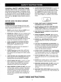
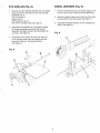
Fig. A
IMPROPER ELECTRICAL CONNECTION of the equipment grounding conductor can result in risk of electric
shock. The conductor with the green insulation (with or
without yellow stripes) is the equipment grounding
conductor. DO NOT connect the equipment grounding
conductor to a live terminal if repair or replacement of
the electric cord or plug is necessary.
grounding conductor
electrical
receptacle
_trical
SAVE THESE INSTRUCTIONS.
4
cord
1.
Fig. B
ALWAYS USE THE EYE SHIELDS AND WHEEL
GUARDS provided with the grinder.
grounding
ada
REPLACE A CRACKED OR DAMAGED GRINDING WHEEL IMMEDIATELY. A damaged wheel can
discharge debris at a high velocity towards the
operator. Carefully handle the grinding wheels since
they are abrasive. Prior to replacing a grinding
wheel, check it for cracks. DO NOT remove the
blotter or label on the both sides of the grinding
wheel. Tighten the Spindle nut just enough to hold
the grinding wheel firmly to the Bench Grinder. Do
not over-tighten the nut. Excessive clamping force
can damage the grinding wheel. Only use the wheel
flanges provided with the grinder. When selecting a
replacement grinding wheel, verify that the grinding
wheel has a higher R.EM. rating than the maximum
R.P.M. of the Bench Grinder.
=
grounding conductor
2-prong
electrical
3-wire electrical cord
receptacle
This tool is intended for use on a circuit that has an
electrical receptacle as shown in FIGURE A. FIGURE A
shows a 3-wire electrical plug and electrical receptacle
that has a grounding conductor. If a properly grounded
electrical receptacle is not available, an adapter as
shown in FIGURE B can be used to temporarily connect this plug to a 2-contact ungrounded receptacle.
The adapter has a rigid lug extending from it that MUST
be connected to a permanent earth ground, such as a
properly grounded receptacle box. THIS ADAPTER IS
PROHIBITED IN CANADA.
THE DIAMETER OF THE GRINDING WHEELS
WILL DECREASE WITH USE. Adjust the tool rests
and spark arrestors to maintain a distance of 1/16"
from the wheel.
.
,
side for one minute until the grinder comes up to
full speed. There is always a possibility that debris
from a damaged grinding wheel may be discharged
towards the operator.
CAUTION: In all cases, make certain the electrical
receptacle in question is properly grounded. If you are
not sure have a certified electrician check the electrical
receptacle.
,.
This Bench Grinder is for indoor use only. To avoid
serious injury, do not expose to rain or use in damp
locations.
,
SPECIFIC SAFETY INSTRUCTIONS
FOR BENCH GRINDERS
The operation of any grinder can result in debris being
thrown into your eyes, which can result in severe eye
damage. ALWAYS wear Safety Goggles (that comply
with ANSI standard Z87.1) when operating the grinder.
Safety Goggles are available at Sears Retail Stores.
Keep your thumbs and fingers away from the grinding
wheels.
DO NOT STAND IN FRONT OF THE BENCH
GRINDER WHEN STARTING IT. Stand to one side
of the Bench Grinder and turn it "ON". Wait at the
THE BENCH GRINDER WILL PRODUCE
SPARKS AND DEBRIS DURING GRINDING
OPERATIONS. Be sure that there are not any flammable materials in the vicinity. Frequently clean
grinding dust from the back of the Bench Grinder.
NEVER FORCE THE WORKPIECE AGAINST A
GRINDING WHEEL, especially if the wheel is cold.
Apply the workpiece slowly, allowing the grinding
wheel an opportunity to warm up. This wilt minimize
the chance of wheel breakage. DO NOT grind using
the sides of the grinding wheels. DO NOT apply
coolant directly to the grinding wheel.
7.
KEEP ALL WHEEL GUARDS IN PLACE. DO NOT
USE THE BENCH GRINDER WITH THE WHEEL
GUARDS REMOVED.
8.
KEEP THE TOOL RESTS FIRMLY TIGHTENED.
9.
ALWAYS USE THE SUPPLIED WHEEL DRESSER
TO RESURFACE THE FACE OF THE GRINDING
WHEEL.
SAVE THESE iNSTRUCTiONS.
AVAILABLE
ACCESSORIES
Sears may recommend other accessories not listed in
this manual.
Visit your Sears Hardware Department or see the Sears
Power and Hand Tool Catalog for the following
accessories.
ITEM
STOCK NUMBER
Replacement grinding wheels
See catalog or store
Wire and Buffing wheels
See catalog or store
Spacers
See catalog or store
Wheel dressers
See catalog or store
Universal stand
See catalog or store
See your nearest Sears Hardware Department or Sears
Power and Hand Tool Catalog for other accessories.
Do not use any accessory unless you have completely
read the Owner's Manual for that accessory.
Use only accessories recommended for this Bench
Grinder. Using other accessories may cause serious
injury and cause damage to the Bench Grinder.
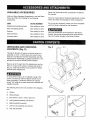
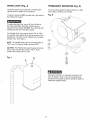
UNPACKING AND CHECKING
CONTENTS (Fig. C)
Fig. C
This Bench Grinder will require a minimal amount of
assembly. A 12mm x 10mm open end wrench is provided for mounting the Tool Rest Assemblies and the
Spark Arrestor Assemblies. A philips screwdriver is not
provided to mount the Wheel Dresser Support
Remove all of the parts from the shipping box and lay
them on a clean work surface. Compare the items to
(Fig. C), verify that all items are accounted for before
discarding the shipping box.
A
To avoid serious injury, do not attempt to plug in the
power cord and turn "ON" the Bench Grinder if any
parts are missing. The Bench Grinder can only be
turned "ON" after all the parts have been obtained and
installed correctly.
B
C
The following items are to be provided in the shipping
box:
A.
Grinder
B. Wheel dresser
C.
Hex Wrench 12mm x 10mm open end
D.
Left Eyeshield assembly (not shown)
E.
Right Eyeshield assembly
F.
Left tool rest assembly (not shown)
G
G. Tool rest assembly
6
D
7
16
17
1
8
5
5
I
13
6
11B
i0
9
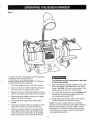
12
1. WHEEL GUARD - Covers the grinding wheels and
protects against accidental contactl
11. A) 8" GRINDING WHEEL 60 GRIT - Used to
remove light material from workpiece.
2. WHEEL COVER - Covers the grinding wheels and
provides access for routine maintenance.
11. B) 8" GRINDING WHEEL 36 GRIT- Used to
remove heavy material from workpiece.
3. MOTOR HOUSING - Contains the electrical motor.
12. ON / OFF SWITCH - Used to turn "ON" and turn
4. MOUNTING
the grinder.
FEET - Helps to minimize vibration of
"OFF" the grinder.
5. EYE SHIELD MOUNTS - Supports the eyeshields.
13. WHEEL DRESSER - Used to clean and smooth
surface of the 8" Grinding Wheel.
6. EYE SHIELDS - Protective Lexan see-thru shields
to prevent any loose debris from contacting the
operator.
14. MOUNTING PAD - Used to secure the grinder to a
workbench or suitable work surface.
15. GRINDING WHEEL IDENTIFICATION LABEL Provides information on wheel size, grit and maximum rpm. Must be left on to distribute the load of
tightening the Lock Nuts.
7. FLEXIBLE WORK LIGHT - Provides assistance to
the operator for grinding operations.
8. SPARK ARRESTORS - Prevents hot sparks and
debris from contacting the operator.
16. FLANGES - Used to secure the grinding wheels to
the grinder and distribute the load of the Lock Nuts.
9. TOOL REST ADJUSTABLE SUPPORTS - Lets the
operator position the tool rest closer to the wheel as
the wheel decreases in diameter due to wear.
17. LOCK NUT - Used to secure the grinding wheels to
the grinder.
10. TOOL RESTS - Used to support the workpiece that
is being ground. Adjustable to provide angled
surfaces.
_7
A 12mmx 10mmopenendwrenchis providedfor
mounting
theToolRestAssemblies
andtheSpark
ArrestorAssemblies.
Aphilipsscrewdriver
is not
providedtomounttheWheelDresserSupport.
1,
DO NOT assemble the Bench Grinder until you are
sure the tool IS NOT plugged in,
2,
DO NOT assemble the Bench Grinder until you are
sure the power switch is in the "OFF" position,
3,
DO NOT assemble the Bench Grinder until you are
sure the grinding wheels are firmly tightened to the
Bench Grinder,
TOOL RESTS (Figs.
Fig. E
E
H
F
G
D and E)
The Bench Grinder is provided with two different Tool
Rests assemblies, The Left Side Tool Rest is entirely
flat, The Right Side Tool Rest is also flat,
1,
2,
3,
4.
._ : k_I ,
Remove both Tool Rest Assemblies from the plastic
bags and check to see that you have the following.
Left Side Tool Rest
Left Side Tool Rest Support
Right Side Tool Rest
Right Side Tool Rest Support
5/16" Flat Washer (qty, 6)
5/16-18 x 5/8" Hex head screw (qty, 4)
Adjustment Knob (qty, 2)
SPARK ARRESTORS
.
Assemble the Tool Rest Supports (A) to the inside
surface of the Wheel Covers (B) with the flat
washers (C) and hex head screws (D) as shown,
See Figure D.
,
Assemble the Tool Rests (E) to the Supports (F)
with the flat washers (G) and Adjustment Knobs (H)
as shown. See Figure E,
3,
Adjust each Tool Rest until its inside edge (I) is 1/16"
from the grinding wheel, Firmly tighten the hex
head screws holding the supports, See Figure E,
Remove both Spark Arrestor Assemblies from the
plastic bags and check to see that you have the
.following.
Left Side Spark Arrestor
Right Side Spark Arrestor
1/4" Flat Washer (2)
1/4-20 x 1/4" Hex head screw (2)
Assemble the Spark Arrestors (A) to the inside
surface of the Wheel Covers (B) with the flat
washers (C) and hex head screws (D) as shown.
See Figure F.
Adjust each Spark Arrestor until the lower edge (E)
is 1/16" from the grinding wheel, Firmly tighten the
hex head screws. See Figure F,
Fig. F
Fig. D
B
C
D
8
(Fig. F)
EYE SHIELDS
WHEEL
(Fig. G)
Remove both Eye Shield Assemblies from the plastic
bags and check to see that you have the following.
Eyeshield (qty. 2)
Lock Knob (qty. 2)
Spacer (qty. 2)
M6 Flat washer (qty. 2)
M6 x 80mm carriage head screw (qty. 2)
1,
,
.
Assemble the eyeshield (C) to the Spark Arrestor
(A) inserting carriage head screw (B) through
Eyeshield, the Spark Arrestor, and the Spacer (D)
as shown. See Figure G.
Assemble the flat washer (E) and Lock Knob (F)
to the carriage head screw and tighten until the
Eyeshield remains in the desired position.
See Figure G.
DRESSER
(Fig. H)
1.
Remove the Wheel Dresser, the plastic Support, and
the two #10-24 x 3/8" screws from the plastic bag.
2.
Attach the plastic Support (A) to the top of the motor
housing with the two screws (B). See Figure H.
3.
Assemble the Wheel Dresser (C) to the Support as
shown. See Figure H.
Fig. H
C
Fig. G
D
B
E
C
A
F
A
WORK LIGHT (Fig. J)
PERMANENT
The Bench Grinder is provided with a Flexible Work
Light to assist in visibility of the workpiece.
You should firmly attach the Bench Grinder to a solid
work surface, hardware not included.
The Bench Grinder is NOT provided with a light bulb for
the Flexible Work Light.
Fig. K
MOUNTING
(Fig. K)
To reduce the risk of fire, use a 120 volt, 40 Watt or
less Track Light Bulb, Type R20, medium base or
equivalent (not included). DO NOT use a light bulb that
extends past the end of the light housing.
The Flexible Work Light may be turned "ON" or "OFF"
by using the rotary switch (B) on the top surface of the
housing (A). The switch can be rotated in the clockwise
direction only. See Figure J.
NOTE: The Flexible Work Light can be turned "ON" or
"OFF" even if the Bench Grinder is turned "OFF".
CAUTION: The Flexible Work Light housing will remain
hot for a few minutes after turning it "OFF". Avoid
contact with housing until it is cool.
Fig. J
B
A
If the Bench Grinder is not securely mounted, it will
have the ability to move or tip over during grinding
operations and possibly cause the operators fingers to
contact the grinding wheels.
10
Fig. L
The Bench Grinder is designed for hand held grinding,
sharpening, and cleaning operations.
ALWAYS WEAR EYE PROTECTION!
produced during grinding operations.
To avoid serious injury, never grind on the sides
of the grinding wheels.
Hot sparks are
1.
The Power Switch must be in the "OFF" position.
2.
Stand to the side of the Bench Grinder and plug in
the power cord to a suitable power source.
3.
Remain to the side of the Bench Grinder and turn it
8.
grinding wheels to come to a complete stop.
9.
"ON" by moving the power switch to the up position.
4.
5.
.
.
After completing the grinding operations, turn "OFF"
the Bench Grinder by pushing down on the Power
Switch. CAUTION: It will take a few minutes for the
Allow the grinding wheels to come up to a steady
speed for at least one minute.
Turn "OFF" the Flexible Work Light. CAUTION: The
Flexible Work Light housing will remain hot for a
few minutes after turning it "OFF".
10. Avoid contact with housing until it is cool. Unplug
the Bench Grinder from the power source.
The Flexible Work Light may be turned "ON" if
desired.
NOTE: To prevent unauthorized use of the Bench
Grinder, the power switch has a removable locking key.
With the power switch in the "OFF" position, pull the
locking key out. The Bench Grinder cannot be turned
"ON" with the key removed. Insert the locking key to
resume grinding operations.
Adjust the eyeshields. Place the workpiece on the
appropriate tool rest for the desired operation.
Move the workpiece towards the grinding wheel
until it lightly touches. Move the workpiece back
and forth across the front surface of the grinding
wheel removing the amount of material desired.
11
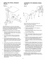
USING THE WHEEL
(Fig. M)
DRESSER
CHANGING
(Fig. N)
Fig. M
THE GRINDING
WHEEL
Fig. N
G
\
C
A
J
IVi
K
B
L
H
Due to normal wear, both wheels will need to be
replaced occasionally. See Figure N.
The Wheel Dresser is to be used on the grinding
wheels. It will remove buildup of material on the grinding wheel, remove imperfections and make the corners
of the grinding wheel square. See Figure M.
1.
Turn the power switch "OFF" and unplug the power
cord from its power source
2.
Rotate the eyeshields to the"UP"
access to the tool rests.
.
DO NOT use the Wheel Dresser on the Wire Wheel.
Make sure the right side tool rest (A) is in the flat
horizontal position as shown and 1/16" away from
the grinding wheel.
,
Turn "ON" the Bench Grinder. Let the grinding
wheel (C) come up to a steady speed for one
minute.
,
After the grinding wheel has gotten to a steady
speed, place the Wheel Dresser (B) flat on the Tool
Rest with the serrated wheels facing the grinding
wheel.
,
Firmly hold on to the handle of the Wheel Dresser.
5.
Move the Wheel Dresser forward until the serrated
wheels make light contact with the grinding wheel.
After contact has been made, slide the Wheel
Dresser side to side across the Tool Rest to dress
the grinding wheel until the edge of the grinding
wheel is square and the surface is clean.
,
.
8,
4.
After the operator has completed dressing the
grinding wheel, turn "OFF" the Bench Grinder and
let the grinding wheel come to a complete stop.
Inspect the grinding wheel for any damage!
position for
Remove the screws (F) holding the Wheel Covers
(E) to the Bench Grinder.
Remove the Wheel Covers.
,
Place a small wooden wedge between the Abrasive
wheel and Tool Rest to prevent the wheels from
rotating.
,
Remove the right side grinding
Iocknut in the counterclockwise
wrench (not included). The left
removed by turning the Iocknut
direction.
.
Remove the Outer Wheel Flange (C) and then remove the abrasive wheel (B) from the arbor shaft (A).
,
CAUTION; The new abrasive wheel to be put onto the
Bench Grinder must be have a higher R.P.M. rating
than the Bench Grinder. The abrasive wheel must
have a 8" diameter with a 5/8" bore diameter for the
arbor shaft. The label on the side of the abrasive
wheels must stay on, DO NOT remove this label.
,
Replace the abrasive wheel, outer wheel flange,
and the Iocknut in reverse order from removal.
wheel by turning the
direction with a
side wheel can be
(D) in the clockwise
CAUTION: DO NOT OVER=TIGHTEN the lock nut as
this may damage the abrasive wheel and cause serious
injury to the operator.
The grinding wheel may now be slightly smaller in
diameter after dressing. Readjust the tool rests and
spark arrestors to maintain a 1/16" clearance to the
grinding wheel.
12
CAUTION: REPLACE the abrasive wheels if there is
any damage at all. FAILURE to replace a damaged
wheel can cause serious injury to the operator.
Turnthe powerswitch"OFF"andunplugthepower
cordfromitspowersourcepriortoanymaintenance.
CAUTION: DO NOT USE FLAMMABLE MATERIALS
to clean the Bench Grinder. A clean dry rag or brush is
all that is needed to remove dust and debris buildup.
LUBRICATION
The Bench Grinder has sealed lubricated bearings in
the motor housing that do not require any additional
lubrication from the operator.
Repairs to the Bench Grinder should be performed by
trained personnel only. Contact your nearest Sears
Canada Inc. outlet for authorized service. Unauthorized
repairs or replacement with non-factory parts could
cause serious injury to the operator and damage to the
Bench Grinder.
CLEANING
With the Bench Grinder unplugged, rotate the abrasive
wheels slowly and inspect for any damage or trapped
shavings.
TO PREVENT INJURY TO YOURSELF or damage to the Bench Grinder, turn the switch to the "OFF" position and
unplug the power cord from the electrical receptacle before making any adjustments.
LIKELY CAUSE(S)
SOLUTION
Motor does
not run
1.
2.
3.
4.
5.
1.
2.
3.
4.
5.
Motor does not
1. Incorrect line voltage
PROBLEM
Machine not plugged in
Power switch in "OFF" position
Power cord is faulty
Fuse or circuit breaker are open
Damaged motor
Plug power cord into electrical receptacle
Lift switch to "ON" position
Return to Sears Service Center
Overloaded electrical circuit
Return to Sears Service Center
2. Damaged motor
1. Have a qualified electrician check line for proper
voltage.
2. Return to Sears Service Center
Motor runs hot
1. Motor is overloaded
2. Poor air circulation around motor
1. Reduce pressure on workpiece
2. Remove any blockage around motor
Motor stalls or
or runs slow
1. Motor is overloaded
2. Incorrect line voltage
1. Reduce pressure on workpiece
2. Have a qualified electrician check line for proper
voltage
3. Return to Sears Service Center
have full power
3. Capacitor has failed
Fuse blows or
circuit breaker
trips
1. Motor overloaded
2. Overloaded electrical circuit
3. Wrong fuse or circuit breaker
4. Undersized or excessive length
of extension cord, see manual
5. Grinding wheels are blocked
1.
2.
3.
4.
Reduce pressure on workpiece
Reduce the amount of items on circuit
Replace with correct fuse or circuit breaker
Use correct size
5. Unplug machine and remove obstruction
13
8-IN. BENCH GRINDER PARTS LIST
When servicing, use only CRAFTSMAN
product damage.
MODEL NO.152.241180
replacement parts. Use of any other parts may create a HAZARD or cause
Any attempt to repair or replace electrical parts on this Bench Grinder may create a HAZARD unless repair is done
by a qualified service technician. Repair service is available at your nearest Sears Service Center.
Always order by PART NUMBER, not by key number.
Key No.
Qty.
PART No.
Description
Qty.
Key No.
PART No.
Description
1
2
3
4
5
OR90055
OR90152
STD851006
OR90001
OR90002
CARRIAGE HD SCREW M6 x 80mm
EYESHIELD
FLAT WASHER M6
KNOB M6
SPACER
1
1
1
1
1
41
42
43
44
OR90205
OR90007
STD512505
OR90303
1
1
3
45
OR90188
WHEEL GUARD-LEFT
ROTATION LABEL
TRUSS HD SCREW 1/4-20 x 1/2"
8" GRINDING WHEEL 36 GRIT
8" DIAMETER x 3/4" WIDE x 5/8" BORE
FLANGE
6
7
8
9
lO
OR90003
STD551012
OR90150
STD511002
OR90187
SPARK BREAKER-RIGHT
FLAT WASHER 1/4"
HEX HD SCREW 1/4-20 x 1/4"
TRUSS HD SCREW #10-24 x 1/4"
COVER
1
1
1
4
1
46
47
48
49
50
OR90372
OR90187
STD511002
OR90207
OR90166
HEX NUT5/8-11
L.H
COVER
TRUSS HD SCREW #10-24 x 1/4"
POWER CORD
STRAIN RELIEF<6N-4>
11
12
13
1
1
4
1
1
OR90370
OR90188
OR91302
1
2
51
52
53
54
55
STD511003
OR90031
OR90308
OR90210
OR90317
TRUSS HD SCREW #10-24 x 3/8"
CORD MOUNTING PLATE
BASE
LIGHT ASSY
LIGHT WARNING LABEL
2
1
1
1
1
56
57
58
59
60
OR90481
OR90037
OR90038
STD511002
STD551125
SWITCH MOUNTING PLATE
SWITCH
SWITCH KEY
TRUSS HD SCREW #10-24 x 1/4"
LOCK WASHER 1/4"
1
1
1
2
2
61
62
63
64
65
STD54t025
OR90310
OR90045
STD551010
STD511005
HEX NUT 1/4"-20
COVER PLATE
RUBBER PAD
FLAT WASHER #10
ROUND HD SCREW #10-24xl/2"
2
1
4
4
4
66
67
68
69
70
OR90311
STD511003
OR90169
STD511003
OR90053
CAPACITOR<12uf
; 250V.AC>
TRUSS HD SCREW #10-24x3/8"
CAPACITOR CLAMP
TRUSS HD SCREW #10-24x3/8"
EXT TOOTH WASHER M5.3
1
1
1
1
2
71
72
73
74
N/A
OR90212
STD511002
OR90049
OR90050
OR91301
DRESSER HOLDER
TRUSS HD SCREW #10-24 x 1/4"
WHEEL DRESSER
OPEN END WRENCH 10ram x 12mm
OWNER'S MANUAL NOT SHOWN)
1
2
1
1
1
14
15
OR90190
OR90007
HEX NUT 5/8-11 R.H.
FLANGE
8" GRINDING WHEEL 60 GRIT
8" DIAMETER x 3/4" WIDE x 5/8" BORE
WHEEL GUARD-RIGHT
ROTATION LABEL
16
17
18
19
2O
STD512505
OR90191
OR90192
OR90155
STD551031
TRUSS HD SCREW 1/4-20 x 1/2"
TOOL REST SUPPORT-RIGHT
TOOL REST-RIGHT
KNOB 5/16-18
FLAT WASHER 5/16"
3
1
1
1
1
21
22
23
24
25
STD551031
STD523105
OR91304
'
OR91305
OR91306
FLAT WASHER 5/16"
HEX HD SCREW 5/16-18 x 1/2"
GROMMET
MOTOR ASSY
NAMEPLATE
2
2
1
1
1
26
27
28
29
30
OR91307
OR90001
STD851006
OR90152
OR90055
SPEC PLATE
KNOB M6
FLAT WASHER M6
EYESHIELD
CARRIAGE HD SCREW
1
1
1
1
1
31
32
33
34
35
OR90002
OR90025
OR90150
STD551012
OR90203
SPACER
SPARK BREAKER-LEFT
HEX HD SCREW 1/4-20 x 1/4"
FLAT WASHER 1/4"
TOOL REST SUPPORT-LEFT
1
1
1
1
1
36
37
38
39
40
OR90204
STD551031
OR90155
STD551031
STD523105
TOOL REST-LEFT
FLAT WASHER 5/16"
KNOB 5/16-18
FLAT WASHER 5/16"
HEX HD SCREW 5/16-18 x 1/2"
1
1
1
2
2
M6 x 80mm
1
1
1
14
<
<
_
•
_
_ _ h
_/_
9
Z
Ug
I"11
Z
o
Z
11
12
Q
:D
Z
I"11
]6
72
71
/
26
3]
34
19
49
37
51
52
53
58
5 57
_-59
0
m
r-
62
z
0
<
o
_' NOTES ,_
16
Your
ome
For repair- in your home - of all major brand appliances,
lawn and garden equipment, or heating and cooling systems,
no matter who made it, no matter who sold it!
For the replacement parts, accessories and
owner's manuals that you need to do-it-yourself.
For Sears professional installation of home appliances
and items lime garage door openers and water heaters.
1-800-4-1VlY-HOIVlE ® (1-800-469-4663)
Anytime, day or night (U.S.A. only)
www, sears.com
ur Home
For repair of carry-in products like vacuums, lawn equipment,
and electronics, call or go on-line for the location of the nearest
Sears Parts & Repair Center.
1-800-488° 1222
Anytime, day or night (U.S.A. only)
www.sears.com
To purchase
a protection
1-800-827-6655
(u.s.A.)
Para pedir servicio de reparaci6n a
domicilio, y para ordenar piezas:
1-888=SU-HOGAR
agreement
on a product
serviced
by Sears:
1=800-361-6665
Au Canada
sM
(Canada)
pour service en fran(2ais:
1-800-LE-FOYER
"c
(1-800-533-6937)
www.sears.oa
(1-888-784-8427)
8 /.4R8
® Registered Trademark / TM Trademark / SMService Mark of Sears, Roebuck and Co.
® Marca Registrada / TMMarca de FAbrica / SMMarcade Servicio de Sears, Roebuck and Co.
MCMarque de commerce / M°Marque d6pos_e de Sears, Roebuck and Co.
© Sears, Roebuck and Co.