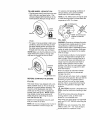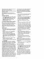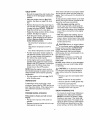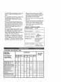
1
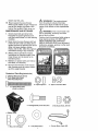
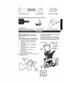
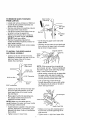
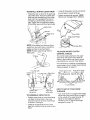
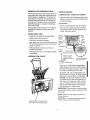
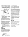
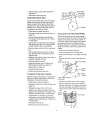
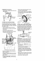
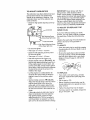
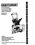
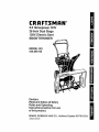
CRRFTSMRN ® 5.5 Horsepower OHV 26 Inch Dual Stage 120V. Electric Start SNOWTHROWER MODEL NO. 536.886150 Caution: Read and follow all Safety Rules and Operating Instructions before first use of this product. SEARS, ROEBUCK 340804 06/28t96 AND CO., Hoffman Estates 60179 U.S.A. Table of Contents Warranty Safety Rules Contents of Shipping Carton Assembly Operation Maintenance LIMITED TWO-YEAR 2 2 2-4 4-5 5-8 8 -t 4 14-t 6 WARRANTY Service and Adjustments Storage Troubleshooting Repair Parts Engine Repair Parts Span ish (Espa5o t) Parts Ordering/Service ON CRAFTSMAN SNOW 17-21 22 23 24-34 35-40 41-65 Back Cover THROWER For two years from the date of purchase, when this Craftsman Snow Thrower is maintained, lubricated, and tuned up according to the operating and maintenance instructions in the owner's manual, Sears will repair, free of charge, any defect in material or workmanship. If this Craftsman Snow Thrower is used for commercial or rental purposes, this warranty_applies for only 90 days from the date of purchase This warranty does not cover the following: • Items which become worn during normal use, such as spark plugs, drive belts and shear pins. . Repairs necessary because of operator abuse or negligence, including bent crank shafts and the failure to maintain the equipment according to the instructions conrained in the owner's manual WARRANTY SERVICE IS AVAILABLE BY RETURNING THE CRAFTSMAN SNOW THROWER TO THE NEAREST SEARS SERVICE CENTER/DEPARTMENT IN THE UNITED STATES. THIS WARRANTY APPLIES ONLY WHILE THIS PRODUCT IS IN USE IN THE UNITED STATES This warranty gives you specific legal rights, and you may also have other rights which may vary from state to state Sears, Roebuck and Co,, D817WA, Hoffman Estates, IL 60179 /k Look for this symbol to point out important safety precautions. ATTENTION!!! Become alert!!! Your safety is involved_ A CAUTION: Always disconnect spark plug wire and place wire where it cannot contact spark plug to prevent accidental starting when setting-up, transporting, adjusting or making repairs IMPORTANT: Safety standards require operator presence controls to minimize the risk of injury, Your snow thrower is equipped with such controls,, Do not attempt to defeat the function of the operator presence control under any circumstances, TRAINING 1. Read the operator's manual carefully Be thoroughly familiar with the controls and the proper use of the snow thrower. Know how to stop the snow thrower and disengage the controls quickly 2. Never allow children to operate the snow thrower and keep them away while it is It means--- operating Never allow adults to operate the snow thrower without proper instruction. Do not carry passengers 3 Keep the area of operation clear of all persons, particularly small children and pets 4, Exercise caution to avoid slipping or falling, especially when operating in reverse PREPARATION 1 Thoroughly inspect the area where the snow thrower is to be used and remove all doormats, sleds, boards, wires and other foreign objects 2 Disengage all clutches before starting the engine (motor) 3 Do not operate the snow thrower without wearing adequate winter outer garmentsoWear footwearthatwill improvefootingonslipperysurfaces. 4. Handlefuelwithcare;it is highly flammable. (a)Useanapproved fuelcontainer. (b)Neverremovefueltankcapor add fueltoa runningengineor hot engine_ (¢)Fillfueltankoutdoorswithextreme care Neverfillfue!tankindoors. (d)Replacefueltankcapsecurelyand wipeupspilledfuel. (e)Neverstorefuelor snowthrower withfuelinthetankinsideof a buildingwherefumesmayreachan openflameor spark (f) Checkfuelsupplybeforeeachuse, allowingspaceforexpansion asthe heatoftheengine(motor)and/orsun cancausefuelto expand. 6o 7o 8. 9. S. Use extension cords and receptacles as specified by the manufacturer for all snow throwers with electric drive motors or electric starting motors. 10. Do not run the engine indoors, except when starling the engine and for transporting the snow thrower in or out of the building.. Open the outside doors; exhaust fumes are dangerous (containing CARBON MONOXIDE, an ODORLESS and DEADLY GAS). 11 Do not clear snow across the face of slopes Exercise caution when changing direction on slopes. Do not attempt to clear steep slopes 12 Never operate the snow thrower without proper guards, plates or other safety protective devices in place 13 Never operate the snow thrower near glass enclosures, automobiles, window wells, drop-offs, and the like Without proper adjustment of the snow discharge angle Keep children and pets away. 14. Do not overload the machine capacity by attempting to clear snow at too fast a rate. 6o Adjust the snow thrower height to clear gravel or crushed rock surfaces. 7. Never attempt to make any adjustments while the engine (motor) is running (except when specifically recommended by the manufacturer), 8. Let engine (motor) and snow thrower adjust to outdoor temperatures before starting to clear snow. g. Always wear safety glasses or eye shields during operation or while performing an adjustment or repair to protect eyes from foreign objects that may be thrown from the snow thrower OPERATION 1. Do not operate this machine if you are taking drugs or other medication which can cause drowsiness or affect your ability to operate this machine 2. Do not use this machine if you are mentally or physically unable to operate this machine safely. 3 Do not put hands or feet near or under rotating parts. Keep clear of the discharge opening at all times 4. Exercise extreme caution when operating on or crossing gravel drives, walks, or roads. Stay alert for hidden hazards or traffic 5. After striking a foreign object, stop the engine (motor), remove the wire from the spark plug, disconnect the cord on electric motors, thoroughly inspect the snow thrower for any damage, and repair the damage before restarting and operating the snow thrower, If the snow thrower should start to vibrate abnormally, stop the (motor) and check immediately for the cause. Vibration is generally a warning of trouble. Stop the engine (motor) whenever you leave the operating position, before unclogging the auger/impeller housing or discharge guide, and when making any repairs, adj_Jstments, or inspections. When cleaning, repairing, or inspecting, make certain the auger/impeller and all moving paffs have stopped. Disconnect the spark plug wire and keep the wire away from the plug to prevent accidental starting. Take all possible precautions when leaving the snow thrower unattended Disengage the augedimpeller, shift to neutral, stop engine, and remove key 15. Never operate the snow thrower at high transport speeds on slippery surfaces.. Look behind and use care when backing. 16. Never direct discharge at bystanders or allow anyone in front of the snow thrower.. 17 Disengage power to the auger/impeller when snow thrower is transported or not in use 18. Use only attachments and accessories approved by the manufacturer of the snow thrower (such as tire chains, 3 electric start kits, etc.). 19. Never operate the snow thrower without good visibility or light,. Always be sure of your footing, and keep a firm hold on the handles° Walk; never run. WARNING: The engine exhaust from this product contains chemicals known to the State of California to cause cancer, birth defects or other reproductive harm_ MAINTENANCE ,/_ AND STORAGE WARNING: This snow thrower is for use on sidewalks, driveways and other ground level surfaces,, 1o Check shear bolts and other bolts frequently for proper tightness to be sure the snow thrower is in safe working condition. Caution should be exercised while using on steep sloping surfaces, DO NOT USE SNOW THROWER ON SURFACES ABOVE GROUND LEVEL such as roofs of residences, garages, porches or other such structures or buildings, 2, Never store the snow thrower with fuel in the fuel tank inside a building where ignition sources are present such as hot water and space heaters, clothes dryers, and the like Allow the engine to _._.j._/'#,_ cool before storing in any enclosure, 3. Always refer to operator s manual instructions for important details ff the snow thrower is to be stored for an extended period° 4, Maintain or replace safety and instruction labels, as necessary. 5, Run the snow thrower a few minutes after throwing snow to prevent freezeup of the auger/impeller. Contents of Parts Bag (actual _'i'_i_![_7._ 2_..,., _._,._,, ___._,_'_J_$J_ _': _..__ ¢_ _ }]_,_._._._ _._.'.._. _'._ __'_"_'_/_ size) 1 - Owner's Manual (not shown) 2 - Parts Bags (not shown) *Non-Assembly Parts ©D @© *2 - Spare Spacers *2 - Spare 1/4-20 Hex Nuts (114_20 x 1-3/4 In.) 3 -Carriage Bolts, 5f16-18xl .00 In 3 -Hex Nylon Nuts, 5/16-18 1- Shifter Knob 1- Nul, 1/2-13 Hexjam 5 - 11/32 Flatwashers 4 1 - Starter Motor Cord 10FI, 2- Screw, 5/16-t8 x 2 In. 2 -Washer, Hvsptlk 2- Nut, 5/1648 Reghex Parts packed separately in carton (not shown full size) 2 - Ignition Keys (Attached to engine in plastic bag) _ CAUTION: 1 - container 5W30 oil Always wear safety glasses or eye shields while assembling snow thrower TOOLS REQUIRED FOR ASSEMBLY 1 - Knife to cut carton and plastic ties 2 - 1/2 inch wrenches (or adjustable wrenches) 2 - 9/16 inch wrenches (or adjustable wrenches) 2 - 3/4 inch wrenches (or adjustable wrenches) 1 - Pliers (to spread cotter pin) 1 _ Screwdriver 1 - Snow Chute Assembly The figure below shows the snow thrower completely assembled, References to the right or left hand side of the snow thrower are from the viewpoint of the operator's position behind the unit, Auger drive lever Chute Crank Shifter lever I - Measuring tape or ruler The figure below shows the snow thrower in the shipping carton Lower handle Height adjust Upper handle aF,sembly lever / Mounting nuts I deflector TO REMOVE SNOW FROM CARTON THROWER • Locate and remove container of 5W30 oil. • Locate all parts packed separately and remove from the carton+ • Remove and discard the packing materiat from around the snow thrower • Cut all four corners of the carton from top to bottom and lay the panels flat. • Roll the snow thrower off the carton by pulling on the lower handle+ CAUTION: DO NOT back over cables, . Remove the packing material from handle assembly and plastic protector on top of auger housing • Cut ties securing the clutch control cables to the lower handle TO INSTALL THE UPPER HANDLE AND CRANK ASSEMBLY + Loosen, but do not remove the screw, flatwasher, Iockwasher and hex nut in the right hand upper holes of the Iower handle See next figure, Upper handle tf_efthand) "f 3t8" nylon Iocknut End of Eye Bolt • Cut tie securing upper crank rod to the upper handle, • Carefully remove cotter pin and clevis pin from yoke end of upper crank rod assembly as shown in figure below. Uniersal Joint Pin Cotter Pin Upper/" Crank "" Clevis Rod /./" Upper handle J 5/16" hex Nut "_ f \1 (Righthand) Loosen.but 1/32"Flatwasher 5116"Lockwasher NOTE: If this removes the universal joint and univesaf joint pin. Place universal joint into yoke of upper crank rod lining up large holes. Insert universal joint pin, • While holding universal joint in place slide the upper crank rod down through the eye bolt until the universal joint will slide into the yoke of the lower crank rod+ • Line up open_ngs, insert clevis pin through assembly and secure with cotter pin Spread ends of cotter pin to lock in pIace See figure below, * Loosen, but do not remove the nylon locknut on the eye bolt assembly in the left hand upper holes of the lower handle. See next figure . Raise upper handle into operating position, Upper handle should be to the outside of the lower handle, Universatjoint Lower NOTE: Make sure the cables are not caught between the upper and lower handle or on the gear select bracket • Install hardware supplied in the parts bag (Screws, flatwashers, lockwashers, and Iocknuts) into lower holes on handlesSee figure above . Tighten screws in lower holes Upper Crank Rod Tighten nut on eye bolt, keeping eye in tine with the rod while tightening the inside securely, Tighten screw in right hand upper hole, TO INSTALL SHIFTER LEVER KNOB • Thread the hex nut found in the parts bag onto shifter lever, Thread the shifter lever knob onto the threaded end of the shifter lever until it is snug against the hex nut and the lip is pointed away from the engine. Tighten hex nut against the bottom of the shifter lever knob° See figure below _"\ - Install (3) ftatwashers and (3) nuts (found in parts bag) on outside of flange ,, - Tighten carriage bolts securely, NOTE: Check fourth carriage bolt for tightness., Locknut Knob _\ Nut Shifter Lever _" NOTE_ If the cables have become disconnected from the clutch levers, reinstall the cables as shown in next two figures NOTE: Position cable through slots on shifter plate, , Snow Chute Flange ,,_ _"_Carriage Bolts TO CHECK/ADJUST CONTROL CLUTCH CABLES The control cables attached to the auger clutch lever and traction clutch lever as shown in figure below may need to be adjusted before you use your snow thrower "Z" fitting For instructions on checking or adjusting the control cables. (See To Adjust Clutch Control Cables paragraph on page17) 4" Lg free state Traction drive 3" Lg free stale Auger drive ing HOW TO SET UP YOUR SNOW ve spring lever TO ASSEMBLE spring cable SNOW CHUTE • Position snow chute on snow chute flange and align the three holes in the snow chute with holes in the snow chute flange as shown in next figure • Install (3) carriage bolts (found in parts bag) from inside of chute as shown in next figure° THROWER • Your snow thrower is equipped with height adjust skids (see second figure on page 5) on the outside of the auger housing, To adjust the skid height for different conditions, (see To Adjust Skid Height paragraph on page 17) 4" CHECKLIST Before you operate your new snow thrower, to ensure that you receive the best performance and satisfaction from this quality product, please review the following checklist: •f All assembly instructions have been completed. 4' The discharge chute rotates freely. / No remaining loose parts in carton, except for extra shear bolt assembly parts_ Keep in safe place for replacement. Auger Drive Lever - Starts and stops the auger and impeller (snow gathering and throwing). Traction Drive Lever - PropeEs the snow thrower forward and in reverse. Speed Shifter Lever- Selects the speed of snow thrower (6 speeds forward and 2 speeds reverse),. Crank AssemblyChanges the direction of snow throwing through the discharge chute. Chute Deflector - Changes the distance the snow is thrown. Discharge Chute - Changes the direction the snow is thrown. Height Adjust Skids - Adjusts the ground clearance of the auger housing. While learning how to use your snow thrower, pay extra attention to the following important items: ,/'.f Engine oil is at proper level. ,/,/ Make sure gas tank is filled properly with clean, fresh, unleaded gasoline° /4' Become familiar with all controls-their location and function. Operate controls before starting engine_ Ignition Key - Must be inserted to start the engine,. Recoil Starter Handle - Starts the engine manually. Choke Control - Used to start a cold engine. Primer Button - Injects fuel directly into the carburetor manifold for fast starts in cold weather. Throttle Control - Controls the engine speed. Electric Starter Button - Used to start the engine using the 120 V electric starter. Shear Bolt - Shear bolts are designed to break (to protect the machine) if an object becomes lodged in the auger housing,. Use of a harder bolt wilt destroy the protection provided by the shear bolt KNOW YOUR SNOW THROWER READ THIS OWNER'S MANUAL AND SAFETY RULES BEFORE OPERATING YOUR SNOW THROWER. Compare the illustrations with your SNOW THROWER to famiEiarize yourself with the location of various controls and adjustments Save this manual for future reference, Engine Start Engine Run Off Choke Off Fast Slow Stop Fuel Ignition Key insert to run Drive Clutch Auger Clutch pult out to stop Auger Drive Lever Oii Primer Button |engage [,+_ (f'-_'_ r-t"lPus"tO J electric start Traction Drive Lever Crank Assembly Recoil Starter Handle Primer Button Chute Deflector Speed Lever Chute Starter Button Choke Control Ignition Throttle Control Height Key Skids Shear Bolt Sofa The operation of any snow thrower can result in foreign objects being thrown into the eyes, which can result in severe eye damage. Always wear safety glasses or eye shields while operating the snow thrower. We recommend standard safety glasses or a wide vision safety mask for over your glasses, available at Sears Retail Stores or Service Centers CAUTION: Read owner's manual before operating machine Never direct discharge toward bystanders. Release the auger control bar and stop the engine before unclogging discharge chute or auger housing and before leaving the machine HOWTO USE YOUR SNOW TH ROWE R "lrO STOP YOUR SNOW THROWER o To stop throwing snow, release the auger drive lever (see last figure on this page). • To stop the wheels, release the traction drive lever (see last figure on this page). • To stop the engine, push the throttle control lever to off and pull out (DO NOT TURN) the ignition key, see figure below. Prime button Electric Starter Button Ignition TO MOVE FORWARD • To shift, release the traction drive Iever and move the speed shifter lever to the speed you desire. Ground speed is dotermined by snow conditions. Select the speed you desire by moving the speed shifter lever into the appropriate area on the speed selector. Speeds t, 2 - Wet, Heavy, Extra Deep Speed 3 - Light Speed 4 - Very Light Speeds 5, 6 - Transport only • Engage the traction drive lever as shown in figure below, left hand As the snow thrower starts to move, maintain a firm hold on the handles, and guide the snow thrower along the clearing path. Do not attempt to push the snow thrower • To move the snow thrower backward, move the speed shifter lever into first or second reverse and engage the traction drive lever (left hand) IMPORTANT: Never move the speed shifter lever while the traction lever is down. TO THROW SNOW • Push down the auger drive lever, see figure below • Release to stop throwing snow key Traction Drive Lever Off control Throttle TO CONTROL AND BACKWARD starter handle SNOW DISCHARGE • Turn the crank assembJy to set the direction of the snow throwing. • Loosen the wing knob on the chute deflector and move the deflector to set the distance. Move the deflector (UP) for more distance, (DOWN) for less distance Then tighten the wing knob, see figure below. Auger Drive Lever Off TO USE WHEEL LOCKOUT PIN . The left hand wheel is secured to the axle with a klick pin, see figure below.. This unit was shipped with this kiick pin in the locked position (klick pin through hole in For extreme cold operating conditions of O°F and below, use a partial synthetic 0W30 motor oil for easier starting. NOTE: S.A E. 5W30 motor oil may be used to make starting easier in areas where the temperature is 20 ° E or lower. Fill/Dipstick Locked Position Klick Pin NOTE: Oil level must be between full and add mark 2-Wheel Drive FILL GAS wheel) .. • For ease of maneuverability in light snow conditions, disconnect the klick pin from the wheel locked position and push into the single wheel drive position (klick pin through axle hole onFy), see next figure NOTE: Make sure that the klick pin is in the single wheel drive position, through axle only and not through the hole in wheel Unlocked Position Klick Pin Single Wheel Drive BEFORE STARTING THE ENGINE FILL OIL This snow thrower was shipped with a container of 5W30 motor oil This oil must be added to the engine before operating. Remove the oil fill cap/dipstick and fil! the crank case to (FULL) line on dipstick (20 ounces) (see next figure). NOTE: Engine may already contain some residual oil Check frequently when filling the crankcase,, Do not over fill. Tighten the fill cap/dipstick securely each time you check the oil level NOTE: Oit must be changed after the first 2 hours of operation to extend engine fife WARNING: Experience indicates that alcohol blended fuels (called gasohol or those using ethanol or methanol) can attract moisture which leads to separation and formation of acids during storage. Acidic gas can damage the fuel system of an engine while in storage, To avoid engine problems, the fuel system should be emptied before storage for 30 days or longer Start the engine and let it run until the fuel lines and carburetor are empty, Use the carburetor bowl drain to empty residual gasoline from the float chamber. Use fresh fuel next season (see Storage instructions on page 22 for additional information) Never use engine or carburetor cleaner products in the fuel tank or permanent damage may occur, Fil! the fuel tank with clean, fresh, unleaded grade automotive gasoline Be sure that the container you pour the gasoline from is clean and free from rust or other foreign particles Never use gasoline that may be stale from long periods of storage in the container Z_ CAUTION: Gasoline is flammable and caution must be used when handling or storing it Do not fill rue! tank while snow thrower is running, when it is hot, or when snow thrower is in an enclosed area Keep away from open flame or an electrical spark and DO NOT SMOKE while filling the fuel tank NEVER fill [he tank completely FILL THE TANK to within 1/4" - 1/2" from the topto provide space for expansion of fuel Alwaysfill fueltankoutdoorsandusea funnelor spoutto prevent spilling on the engine first, then plug the other end into the three-hole grounded receptacle_ When disconnecting power cord, always unplug the end in the three-hole grounded receptacle first. Make sure to wipe up any spilled fuel before starting the engine_ Store gasoline in a clean, approved container and keep the cap in place on the container,, TO STOP • Plug the other end of the power cord into a three-hole, grounded 120 volt A,C, receptacle. ENGINE • To stop engine, move the throttle control lever to 1_ (STOP) position and remove key,, Keep the key in a safe place. The engine will not start without the key_ NOTE: DO NOT turn key. TO START ENGINE (Electric • Push the primer button while covering the vent hole as follows: (Remove finger from primer button between primes). See figure on page 9 for location, Do not prime if temperature 50OF, Starter) Two times ff temperature Be sure that the engine has sufficient oil,, The snow thrower engine is equipped with a 120 volt AoCoelectric starter and recoil starter° Before starting the engine, be certain that you have read the following infor_ mation: is above is 50°F to 15°F, Four times if temperature is below 15°F. • Push down on the starter button until the engine starts. Do not crank for more than 10 seconds at a time This electric starter is thermally protected. If overheated it will stop automatically and can be restarted only when it has cooled to a safe temperature (a wait of about 5 to 10 minutes is required), • When the engine starts, release the starter button and slowly rotate the choke to (OFF) position. If the engine falters, rotate the choke to(FULL) and then gradually to (OFF). COLD START • Be sure the auger drive and traction drive levers are in the disengaged (released) position. • Move the throttle control to .t_ (FAST) position, See figure on page 9, . Remove the keys from the plastic bag, Insert one key into the ignition slot, Be sure it snaps into place. DO NOT TURN KEY. Keep the second key in a safe place. • Disconnect the power cord from the receptacle first and then from the switch box on engine., • Rotate the choke knob to (FULL) choke position,, See figure on page 9,, NOTE: Allow the engine to warm up for a few minutes because the engine will not develop full power until it reaches operating temperature • Connect the power cord to the switch box on the engine. _ CAUTION: This starter is equipped with a three-wire power cord and plug and is designed to operate on 120 volt AC household current. It must be properly grounded at all times to avoid the possibility of electrical shock, which may be injurious to operator, Follow all instructions carefully as set forth in the "To Start Engine" section. Determine that your house wiring is a threewire grounded system. Ask a licensed elec_ trician if you are not sure. If your house wire system is not a three-wire system, do not use this electric starter under any conditions. If your system is grounded and a three-hole receptacle is not available at the point your starter will normally be used, one should be installed by a licensed electrician. When connecting 120 volt AC power cord, always connect the cord to the switch box • Run the engine at full throttle "_ when throwing snow, TO STOP (FAST) ENGINE • To stop engine, move the throttle control lever to _ (STOP) position and remove key. Keep the key in a safe place, The engine will not start without the key. NOTE: DO NOT turn key, TO START ENGINE (Recoil Starter) Be sure that the engine has sufficient oil. The snow thrower engine is equipped with a recoil starter Before starting the engine, be certain that you have read the following information: t2 COLD START If the starter still fails to turn engine, repeat the two previous steps until the starter engages. Then continue with the directions for cold start. • Be sure the auger drive and traction drive levers are in the disengaged (released) position. To help prevent possible freeze-up of recoil starter and engine controls, proceed as follows after each snow removal job • Move the throttle control to _ (FAST) position. See figure on page 9 for location. • With the engine running, pull the starter rope hard with a continuous full arm stroke three or four times. Pulling of starter rope will produce a loud clattering sound. This is not harmful to the engine or starter • Remove the keys from the plastic bag. Insert one key into the ignition slot Be sure it snaps into place DO NOT TURN KEY.. Keep the second key in a safe place • Rotate the choke control to (FULL) choke position. See figure on page 9 • With the engine not running, wipe ail snow and moisture from the carburetor cover in area of control levers Also move throttle control, choke control, and starter handle several times. • Push the primer button, see figure on page 9, while covering the vent hole as follows: (Remove finger from primer button between primes) Do not prime if temperature is above 50°E Z_ CAUTION: Never run engine indoors or in enclosed, poorly ventilated areas. Engine exhaust contains CARBON MON_ OXIDE, AN ODORLESS AND DEADLY GAS. Keep hands, feet, hair and loose clothing away from any moving parts on engine and snow thrower. Two times if temperature is 50°F to 15°E Four times if temperature is below 15°E • Pull the recoil starter handle rapidly. Do not allow the handle to snap back, but allow it to rewind slowiy while keeping a firm hold on the starter handle. WARNING: Temperature of muffler and nearby areas may exceed 1500 F..Avoid these areas • As the engine warms up and begins to operate evenly, rotate the choke control slowly to the (OFF) position.. If the engine falters, return to (FULL) choke, then slowly move to the (OFF) position. DO NOT allow children or young teenagers to operate or be near snow thrower while it is operating. Z_ CAUTION: Do no attempt to remove any item that may become lodged in auger without taking the following precautions: NOTE: Allow the engine to warm up for a few minutes because the engine will not develop full power until it reaches operating temperature. • Release auger drive and traction drive levers. • Run the engine at full throttle ,_ (FAST) when throwing snow. WARM • Move throttle lever to stop position. START • Remove (DO NOT TURN) ignition key. • Disconnect spark plug wire. If restarting a warm engine after a short shutdown, Ieave choke at (OFF) and do not push the primer button If the engine fails to start, follow the Cold Start instructions above° FROZEN RECOIL • Do not place your hands in the auger or discharge chute Use a pry bar. SNOW THROWING STARTER TIPS For maximum snow thrower efficiency in removing snow, adjust ground speed, NEVER the throttle Go slower in deep, freezing, or wet snow If the tracks slip, reduce forward speed. The engine is designed to deliver maximum performance at fu]! throttle and should be run at this power setting at all times Most efficient If the starter is frozen and wiil not turn engine: • Putt as much rope out of the starter as possible. • Release the starter handle and let it snap back against the starter. !3 snow blowing is accomplished when the snow is removed immediately after it falls, • For complete snow removal, slightly overlap each path previousJy taken Use more overlap in deep snow to prevent overloading • The snow should be discharged down wind whenever possible. In windy conditions, lower the chute deflector to direct discharged snow close to the ground, where it is less likely to blow into unwanted areas, • For normal usage, set the skids so that the scraper bar is 1/8" above the skids. For extremely hard-packed snow surfaces, adjust the skids upward so that the scraper bar touches the ground • On gravel or crushed rock surfaces, set the skids at 1-1/4" below the scraper bar (See To Adjust Skids Height paragraph on page 17)_ Stones and gravel must not be picked up and thrown by the machine . After the snow throwing job has been completed, allow the engine to idle for a few minutes, which will melt snow and accumulated ice off the engine. • Clean the snow thrower thoroughly after each use • Remove ice and snow accumulation and a[I debris from the entire snow thrower, and flush with water (if possible) to remove all salt or other chemicals. Wipe snow thrower dry. PRODUCT SPECIFICATIONS HORSE POWER: 5.5 HP DISPLACEMENT: 11.88 cu, in GASOLINE CAPACITY: 4 quart (unleaded) 5W-30 OIL (20oz. Capacity) : SPARK PLUG: Champion RN4C (Gap 030) or Equivalent VALVE CLEARANCE: Intake: .010 In. Exhaust: .010 In. CUSTOMER RESPONSIBILITIES SERVICE RECORDS Fill in dates as you complete regular service SCHEDULE SERVICE DATES After 8efor_ first 2 Each Hours Use As Needa_ Every Every 10 Hours 25 Hours Each Season Before Storage = v" Change Engine Oil Level Change Engine Oil , tJ ,t ,=,,, v," v" v" v" ! Tighten atl screws and nuts Check Traction Clutch Cable Adjustment (See cable Adj) fJ Replace Spark Plug Check Drive Botts v" Lubricate all pivo! points Check Auger Clutch Cable Adjustment (See Cabte Adj} Lubricate Disc Drive Plate Zerk v" v,' v" V 'r _ v" t GENERAL RECOMMENDATIONS SNOW THROWER The warranty on this snow thrower does not cover items that have been subjected to operator abuse or negligence, To receive full value from the warranty, the operator must maintain the snow thrower as instructed in this manual The above chart is provided to assist the operator in properly maintaining the snow thrower LUBRICATION FIRST To Lubricate: • Position speed selector lever in first gea_ . Turn disc drive plate clockwise by hand until grease zerk is clearly visible at front center See figure below USE . Check for any loose or damaged paris • Tighten any loose fasteners • Check and maintain the auger . After each use, remove all snow and slush off the snow thrower to prevent freezing of auger or controls - Check controls to make sure they are functioning properly Rubber_ Friction Shalt Wheet Disc (Require No Lubrication) Friction Wheel . If any parts are worn or damaged, replace immediately LUBRICATION 25 HOURS • Lubricate Disc Drive Plate every twenty five (25) hours and at the end of the season and/ or before storage Some adjustments will need to be made pe riodically to properly maintain your snow thrower AFTER - EVERY Grea, Bearing Assembl Place cain in gap between friction wheel and disc dr_ve late r ] E_-Grease Zerk CHART Po_nt grease should be visible • Place a coin or (a shim of equal thickness) between the rubber friction wheel and disc drive plate to prevent rubber fric tion wheel contacting the drive disc • To grease zerk use a hand grease gun, lubricate with a Hi Temp EP Moly grease See inset of second figure on this page DO NOT over fill or allow grease to come in contact with lhe disc drive plate or fric lion wheel or damage will result Fit] zerk only until grease becomes visible below bearing assembly located under grease zerk See insert in figure above IMPORTANT: Remove coin and ensure that a gap exists between friction wheel and disc drive plate NOTE: Clean all excess grease found on friction disc hub CAUTION: Do not allow grease to contact friction wheel and disc drive plate, Lubricate Drive Plate Zerk with a Hi Temp EP Moty Grease 15 LUBRICATION - BEFORE STORAGE OIL RECOMMENDATION • Remove both wheels, grease (any automotive type grease) both axles (see figure below) and replace wheels_ Do this at least once a year and/or prior to storage° Only use high quality detergent oil rated with API service classification SG_ Select the oil's viscosity grade according to your expected operating temperature: NOTE: For extreme cold operating conditions of 0° and below, use a partial synthetic 0W30 motor oil for easier starting° NOTE: Although multi-viscosity oils improve starting in cold weather, these multi-viscosity oils will result in increased oil consumption when used above 32°E Check your engine oil level more frequently to avoid possible engine damage from running low on oil. Change the oil after first two hours of operation, every 25 hours thereafter, and at the beginning of each season • Position the snow thrower so that the oil drain plug is at the lowest point on the engine Remove the oil drain plug and the oil fill cap/dipstick_ Drain the oil into a suitable container Oil wilt drain more freely when warm LUBRICATION • Hex Shaft and Gears - Hex shaft and gears require no lubrication. Alf bearings and bushings are lifetime lubricated and require no maintenance. NOTE: Any greasing or oiling of the above components can cause contamination of the friction wheel. If the disc drive plate or friction wheel comes in contact with grease or oil, damage to the friction wheel wil_ resulto • Replace the oil drain plug and tighten se* curely. SPARK PLUG • Make sure that the spark p_ug is tightened securely into the engine and the spark plug wire is attached to the spark plug_ Should grease or oil come in contact with the disc drive plate or friction wheel, be sure to clean the plate and wheel thoroughly. NOTE: For storage, the hex shaft and gears should be wiped with 5W-30 motor oil to prevent rusting.. See figure above° • If a torque wrench is available, torque plug to 18 to 23 foot pounds • CIean the area around the spark plug base before removal to prevent dirt from entering the engine ° Auger Gear Box - The auger gear box has been factory lubricated for fife tf for some reason lubricant should leak out, have auger gear case checked by a competent repairman.. • Clean the spark plug and reset the gap periodically at .030 inch. ENGINE LUBRICATION Check the crankcase oil level (see figure below) before starting the engine and after each five (5) hours of continuous use. Add SoA.Eo5W30 motor o11as needed. Tighten fill cap/dipstick securely each time you check the oil level. 16 Z_ CAUTION: • Loosen the carriage bolts and nuts securing the scraper bar to the auger housing° Always disconnect the spark plug wire and tie back away from the plug before making any adjustments or repairs. TO ADJUST • Adjust _he scraper bar to the proper position. • Tighten the carriage bolts and nuts, making sure that the scraper bar is parallel with the working surface • For extended operation, the scraper bar may be reversed If the scraper bar must be replaced due to wear, remove the carriage bolts and nuts and install a new scraper bar SKID HEIGHT This snow thrower is equipped with two height adiustment skids, located on the outside of the auger housing (see figure below). These skids elevate the front of the snow thrower. Skid Mounting Nuts CAUTION: Be certain to maintain proper ground clearance for your particular area to be cleared Objects such as gravel, rocks or other debris, if struck by the impeller, may be thrown with sufficient force to cause personal injury, property damage or damage to the snow thrower Auc Hek ust Sklds TO ADJUSTTHE CLUTCH CONTROL For normal hard surfaces, adjust the skids as follows: CABLES • Check tire pressure (14 to '17 pounds) • Place the extra shear bolts supplied (found in parts bag) under each end of the scraper bar near but not under the skid Periodic adjustment of the cables may be required due to normal stretch and wear on the belts To check for correct adjustment, the control lever must be in the full forward position, resting on the plastic bumper. The control cables are correctly adjusted when the center of the "Z" fitting is in the center of the hole and there is no droop in the cable See figure below • Loosen the skid mounting nuts (see figure above) and adjust the skids up to bring the front of the snow thrower down Retighten the mounting nuts • Set the skid on the other side at the same height. Control Lever Auc must be in lu!l For rocky or uneven surfaces, adiust the skids as follows: , Raise the front of the snow thrower by moving the skids down This will help prevent rocks and other debris from being picked up and thrown by the auger TO ADJUST SCRAPER BAR P'_astic Bumper After considerable use, the metal scraper bar will have a definite wear pattern The scraper bar may have to be returned to its original lower setting to maintain the original performance level To adjust: • Position the snow thrower on a level surface. If adjustment is necessary: • Remove fuel from tank, and stand blower on end • Disconnect the "Z" fitting from drive lever. • Pull rubber boot off the top of the spring Push the cable through the spring (see first figure on page 18) to expose the threaded portion of the cable • Make sure both tires are equally inflated Proper tire pressure is 14 to 17 PSL See side of tire for maximum inflation. Do not exceed sidewall maximum pressure on tire _7 AUGER DRIVE BELT If your snow thrower will not discharge snow, and the auger drive belt (see figure below) isdamaged, replace it as follows: Cable spring i Auger Drive Belt _ jSquare end Ddve Pulley Pulley Tractio_ Drive Belt Belt Guide (Left Hand) (Right Hand) Traction Idler • Hold the square end of the threaded portion with pliers and adjust the Iocknut in or out until the excess slack is removed. • Pull the cable back through the spring and connect the cable. Do the same for the other lever cable, if needed NOTE: Whenever the traction drive or auger belts are adjusted or replaced, the cables will need to be adjusted. TO ADJUST AUGER BELT If your snow thrower will not discharge snow, check the control cable adjustment, if it is correct, then check the condition of the auger drive belt, It may be loose or damaged, If it is damaged, replace it (see To Replace Belts paragraph on page 18) DRIVE • Replace the traction drive belt if it is slipping (see To Replace Belts paragraph on page 18)_ TO REPLACE Belt Cover ] l JL_fL"__ ,/ "__tapptng Screw BELT The traction drive belt (see second figure on this page) has constant spring pressure and does not require adjustment BELTS The drive belts on this snow thrower are of special construction and should be replaced with original equipment belts available from your nearest Sears Store or Service Center., You will need the assistance of a second person while replacing the belts Drain the gasoline from the fuel tank by removing the fuef line at the carburetor. Drain the gas into a container and reinstall the fuel line. A . Disconnect the spark plug wire. • Remove the belt cover (see figure below) BELTS DRIVE TRACTION Auger Pulley CAUTION: Drain the gasoline outdoors, away from fire or flame. • Loosen the belt guides (see first figure this column) and pull away from the engine drive pulley, • Loosen nut on the auger idler pulley (see first figure, this column) and pull idler puF ley away from the belt,, • Remove top two bolts that secure auger housing to motor mount frame Loosen bottom two bolts. Auger housing and mo_ tor mount flame will separate, hinged by bottom two bolts, • Remove old belt from the auger drive pulley, • Install the original equipment replacement belt in reverse order of removal. • Position drive belt onto the auger drive puIley • Adjust the belt guides (see To Adjust The Belt Guides paragraph on page 19) • Reinstall the belt cover • Checkclutchcontrolcableadjustment. seepage17. • Reconnect sparkplugwire TRACTIONDRIVE BELT ,,..,,i._-_. j Drive Pulley 3/32 Inch "_k,/" 4_..5_"" Belt Guide Belt Guide.._,...,/\_"" (Left Hand) (Right Hand)_ Ifyoursnowthrowerwillnotmoveforward, checkthetractiondrivebelt(seesecond figureonpage18)forwear(Checkother causesalsointhe TroubleShootingPoints section)°Ifthetractiondrivebeltneedsto be replaced,proceedasfollows: • Disconnect thesparkplugwire • Removethe beltcover(seelastfigureon page18), o Loosenthebeltguidesandpullaway fromenginedrivepulley(seefirst figure onthispage)_ • Loosennutonaugeridlerandpuffauger idlerloulleyawayfrombelt Notelocation ofidlerpulleyforlaterre-installation • Removeaugerdrivebeltfromenginepulley. • Pullthe idlerpulleyaway from the drive ,,._\_,-" 3/32 Inch Auger Idler'_ ._.._.- tmpetler TO ADJUSTTHE FRICTION WHEEL If the snow thrower wilt not move forward, you need to check the traction drive belt, the traction drive cable or the friction wheel If the friction wheel is damaged, it will need to be replaced (see the To Replace Friction Wheel paragraph on page 20) If the friction wheel is not worn, check the adjustment, as foi!ows: • Disconnect the spark plug wire • Drain the gasoline from the gas tank. belt, allowing belt to be positioned onto engine pulley • Stand snow thrower on the auger housing end. • Release idler pulley, Ensure idler pulley is properly engaged with beit • Remove the botlom panel (see figure below) Motor Mount Frame Remove Top Bolts . Reinstall auger drive belt • Adjust belt guides (see To Adjust The Belt Guides paragraph on page 19) • Adjust idler on auger belt • Reinstall the belt cover ;l!i" " Bottom • Reconnect the spark piug wire TO ADJUSTTHE BELT GUIDES After you replace the traction or auger drive belt, you need to adjust one or both of lhe belt guides Proceed as follows: Loosen Bottom Bolls (each sidel 1-'- • Position the shifter iever in first (1) gear, • Note the position of the friction wheel on the disc drive plate The right outer side of the disc drive plate should be 3" from the center of the friction wheel (See figure below) • Disconnect the spark plug wire. • Remove the belt cover (See last figure on page 18) • Engage the auger drive clutch lever • Measure the distance between the bett guides and the belt (See next figure) The distance should be 3/32" for each guide Fricti°n-_'4-}_ ex Shaft • If adjustment is necessary, loosen the belt guide mounting bolts, Move the belt guides to the correct position Tighten the mounting bolts • Reinstall the belt cover \\ • Reconnect the spark plug wire 19 If adjustment is necessary: • Remove right side bearing plate. Leave hex shaft in original position. • Loosen bolts in speed selector lever (see figure below), Speed Selector Lever • Remove frictionwheel from hub, Slip friction wheel off hex shaft towards right side° See figure below. Friction Wheel Lockwasher === Bolts to be Shaft /loosened i TO REPLACE FRICTION Bolt WHEEL Nut Lockwasher If the snow thrower will not move forward, and the friction wheel is worn or damaged, you need to replace it as follows: (First allow the engine to cool), TO REPLACE AUGER SHEAR BOLT The augers are secured to the auger shaft with special bolts (see figure below) that are designed to break (to protect the machine) if an object becomes lodged in the auger housing Use of a harder bolt will destroy the protection provided by the shear bolt. - Drain the gasoline from the fuel tank. ° Drain the fuel in a container and reinstall the fuel line. • Disconnect the spark plug wire, - Stand the snow thrower up on the auger housing end (see figure below), Shear Bolt _ _Shear Friction Bolt -.-_ Bearing PlateBolts Spacer IMPORTANT: To ensure safety and performance levels, only original equipment shear bolts should be used When replacing shear bolts, be sure to replace shear bolt spacers, To replace a broken shear bolt, proceed as follows: Fasteners (Bolts, and nuts)/' • Move the throttle to _ off all controls, (STOP) and turn • Disconnect the spark plug wire, Be sure all moving parts have stopped. ......... • Lubricate the auger shaft by squirting Lubriplate or a fiber impregnated grease into the shear bolt hole in the auger shaft° Then rotate the auger to distribute the oil in the shaft. }=, Unit Standing on Auger Housing End • Remove the bottom panel (see second figure on page 19). • Align the hole in the auger with the hole in the auger shaft Install the new shear bolt and shear bolt spacer provided • Remove the three (3) fasteners securing the friction wheel to the hub (see second figure above), , Reconnect the spark plug wire, • Remove the four bolts securing the bearing plates (both sides), (see second figure above). 2O TO ADJUST CARBURETOR The carburetor (see figure below) has been pre-set at the factory and readjustment should not be necessary. However, if the carburetor does need to be adjusted, proceed as fo