1
U
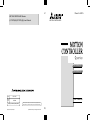
MOTION CONTROLLER Qseries
MOTION CONTROLLERS
(Q173CPU(N)/Q172CPU(N)) User's Manual
Q173CPU (N)
Q172CPU (N)
HEAD OFFICE : 1-8-12, OFFICE TOWER Z 14F HARUMI CHUO-KU 104-6212,JAPAN
NAGOYA WORKS : 1-14 , YADA-MINAMI 5 , HIGASHI-KU, NAGOYA , JAPAN
MODEL
Q173/Q172CPU-USE-E
MODEL
CODE
1CT780
IB(NA)-0300040-B(0205)MEE
IB(NA)-0300040-B(0205)MEE
Printed in Japan
User's Manual
When exported from Japan, this manual does not require application to the
Ministry of Economy, Trade and Industry for service transaction permission.
Specifications subject to change without notice.
Q
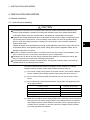
SAFETY PRECAUTIONS
(Read these precautions before using.)
When using this equipment, thoroughly read this manual and the associated manuals introduced in this
manual. Also pay careful attention to safety and handle the module properly.
These precautions apply only to this equipment. Refer to the Users manual of the QCPU module to use
for a description of the PLC system safety precautions.
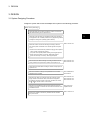
These SAFETY PRECAUTIONS classify the safety precautions into two categories: "DANGER" and
"CAUTION".
DANGER
Indicates that incorrect handling may cause hazardous conditions,
resulting in death or severe injury.
! CAUTION
Indicates that incorrect handling may cause hazardous conditions,
resulting in medium or slight personal injury or physical damage.
!
Depending on circumstances, procedures indicated by ! CAUTION may also be linked to serious
results.
In any case, it is important to follow the directions for usage.
Store this manual in a safe place so that you can take it out and read it whenever necessary. Always
forward it to the end user.
A-1
For Safe Operations
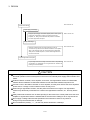
1. Prevention of electric shocks
DANGER
!
Never open the front case or terminal covers while the power is ON or the unit is running, as
this may lead to electric shocks.
Never run the unit with the front case or terminal cover removed. The high voltage terminal and
charged sections will be exposed and may lead to electric shocks.
Never open the front case or terminal cover at times other than wiring work or periodic
inspections even if the power is OFF. The insides of the Motion controller and servo amplifier
are charged and may lead to electric shocks.
When performing wiring work or inspections, turn the power OFF, wait at least ten minutes, and
then check the voltage with a tester, etc.. Failing to do so may lead to electric shocks.
Be sure to ground the Motion controller, servo amplifier and servomotor. (Ground resistance :
100 or less) Do not ground commonly with other devices.
The wiring work and inspections must be done by a qualified technician.
Wire the units after installing the Motion controller, servo amplifier and servomotor. Failing to do
so may lead to electric shocks or damage.
Never operate the switches with wet hands, as this may lead to electric shocks.
Do not damage, apply excessive stress, place heavy things on or sandwich the cables, as this
may lead to electric shocks.
Do not touch the Motion controller, servo amplifier or servomotor terminal blocks while the
power is ON, as this may lead to electric shocks.
Do not touch the built-in power supply, built-in grounding or signal wires of the Motion controller
and servo amplifier, as this may lead to electric shocks.
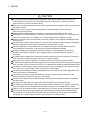
2. For fire prevention
!
CAUTION
Install the Motion controller, servo amplifier, servomotor and regenerative resistor on
inflammable material. Direct installation on flammable material or near flammable material may
lead to fire.
If a fault occurs in the Motion controller or servo amplifier, shut the power OFF at the servo
amplifier’s power source. If a large current continues to flow, fire may occur.
When using a regenerative resistor, shut the power OFF with an error signal. The regenerative
resistor may abnormally overheat due to a fault in the regenerative transistor, etc., and may
lead to fire.
Always take heat measures such as flame proofing for the inside of the control panel where
the servo amplifier or regenerative resistor is installed and for the wires used. Failing to do so
may lead to fire.
A-2
3. For injury prevention
!
CAUTION
Do not apply a voltage other than that specified in the instruction manual on any terminal.
Doing so may lead to destruction or damage.
Do not mistake the terminal connections, as this may lead to destruction or damage.
Do not mistake the polarity ( + / - ), as this may lead to destruction or damage.
Do not touch the servo amplifier's heat radiating fins, regenerative resistor and servomotor, etc.,
while the power is ON and for a short time after the power is turned OFF. In this timing, these
parts become very hot and may lead to burns.
Always turn the power OFF before touching the servomotor shaft or coupled machines, as
these parts may lead to injuries.
Do not go near the machine during test operations or during operations such as teaching.
Doing so may lead to injuries.
4. Various precautions
Strictly observe the following precautions.
Mistaken handling of the unit may lead to faults, injuries or electric shocks.
(1) System structure
!
CAUTION
Always install a leakage breaker on the Motion controller and servo amplifier power source.
If installation of an electromagnetic contactor for power shut off during an error, etc., is specified
in the instruction manual for the servo amplifier, etc., always install the electromagnetic
contactor.
Install the emergency stop circuit externally so that the operation can be stopped immediately
and the power shut off.
Use the Motion controller, servo amplifier, servomotor and regenerative resistor with the combinations listed in the instruction manual. Other combinations may lead to fire or faults.
If safety standards (ex., robot safety rules, etc.,) apply to the system using the Motion controller,
servo amplifier and servomotor, make sure that the safety standards are satisfied.
Construct a safety circuit externally of the Motion controller or servo amplifier if the abnormal
operation of the Motion controller or servo amplifier differ from the safety directive operation in
the system.
In systems where coasting of the servomotor will be a problem during the forced stop,
emergency stop, servo OFF or power supply OFF, use dynamic brakes.
Make sure that the system considers the coasting amount even when using dynamic brakes.
A-3
!
CAUTION
In systems where perpendicular shaft dropping may be a problem during the forced stop,
emergency stop, servo OFF or power supply OFF, use both dynamic brakes and
electromagnetic brakes.
The dynamic brakes must be used only on errors that cause the forced stop, emergency stop,
or servo OFF. These brakes must not be used for normal braking.
The brakes (electromagnetic brakes) assembled into the servomotor are for holding
applications, and must not be used for normal braking.
The system must have a mechanical allowance so that the machine itself can stop even if the
stroke limits switch is passed through at the max. speed.
Use wires and cables that have a wire diameter, heat resistance and bending resistance
compatible with the system.
Use wires and cables within the length of the range described in the instruction manual.
The ratings and characteristics of the parts (other than Motion controller, servo amplifier and
servomotor) used in a system must be compatible with the Motion controller, servo amplifier
and servomotor.
Install a cover on the shaft so that the rotary parts of the servomotor are not touched during
operation.
There may be some cases where holding by the electromagnetic brakes is not possible due to
the life or mechanical structure (when the ball screw and servomotor are connected with a
timing belt, etc.). Install a stopping device to ensure safety on the machine side.
(2) Parameter settings and programming
!
CAUTION
Set the parameter values to those that are compatible with the Motion controller, servo amplifier,
servomotor and regenerative resistor model and the system application. The protective functions
may not function if the settings are incorrect.
The regenerative resistor model and capacity parameters must be set to values that conform to
the operation mode, servo amplifier and servo power supply module. The protective functions
may not function if the settings are incorrect.
Set the mechanical brake output and dynamic brake output validity parameters to values that
are compatible with the system application. The protective functions may not function if the
settings are incorrect.
Set the stroke limit input validity parameter to a value that is compatible with the system
application. The protective functions may not function if the setting is incorrect.
A-4
!
CAUTION
Set the servomotor encoder type (increment, absolute position type, etc.) parameter to a value
that is compatible with the system application. The protective functions may not function if the
setting is incorrect.
Set the servomotor capacity and type (standard, low-inertia, flat, etc.) parameter to values that
are compatible with the system application. The protective functions may not function if the
settings are incorrect.
Set the servo amplifier capacity and type parameters to values that are compatible with the
system application. The protective functions may not function if the settings are incorrect.
Use the program commands for the program with the conditions specified in the instruction
manual.
Set the sequence function program capacity setting, device capacity, latch validity range, I/O
assignment setting, and validity of continuous operation during error detection to values that are
compatible with the system application. The protective functions may not function if the settings
are incorrect.
Some devices used in the program have fixed applications, so use these with the conditions
specified in the instruction manual.
The input devices and data registers assigned to the link will hold the data previous to when
communication is terminated by an error, etc. Thus, an error correspondence interlock program
specified in the instruction manual must be used.
Use the interlock program specified in the special function module's instruction manual for the
program corresponding to the special function module.
(3) Transportation and installation
!
CAUTION
Transport the product with the correct method according to the mass.
Use the servomotor suspension bolts only for the transportation of the servomotor. Do not
transport the servomotor with machine installed on it.
Do not stack products past the limit.
When transporting the Motion controller or servo amplifier, never hold the connected wires or
cables.
When transporting the servomotor, never hold the cables, shaft or detector.
When transporting the Motion controller or servo amplifier, never hold the front case as it may
fall off.
When transporting, installing or removing the Motion controller or servo amplifier, never hold
the edges.
Install the unit according to the instruction manual in a place where the mass can be withstood.
A-5
CAUTION
!
Do not get on or place heavy objects on the product.
Always observe the installation direction.
Keep the designated clearance between the Motion controller or servo amplifier and control
panel inner surface or the Motion controller and servo amplifier, Motion controller or servo
amplifier and other devices.
Do not install or operate Motion controller, servo amplifiers or servomotors that are damaged or
that have missing parts.
Do not block the intake/outtake ports of the servomotor with cooling fan.
Do not allow conductive matter such as screw or cutting chips or combustible matter such as oil
enter the Motion controller, servo amplifier or servomotor.
The Motion controller, servo amplifier and servomotor are precision machines, so do not drop
or apply strong impacts on them.
Securely fix the Motion controller and servo amplifier to the machine according to the instruction
manual. If the fixing is insufficient, these may come off during operation.
Always install the servomotor with reduction gears in the designated direction. Failing to do so
may lead to oil leaks.
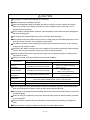
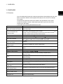
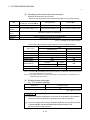
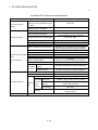
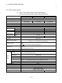
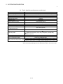
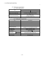
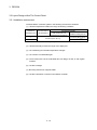
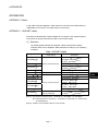
Store and use the unit in the following environmental conditions.
Environment
Ambient
temperature
Ambient humidity
Storage
temperature
Atmosphere
Conditions
Motion controller/Servo amplifier
According to each instruction manual.
According to each instruction manual.
According to each instruction manual.
Servomotor
0°C to +40°C (With no freezing)
(32°F to +104°F)
80% RH or less
(With no dew condensation)
-20°C to +65°C
(-4°F to +149°F)
Indoors (where not subject to direct sunlight).
No corrosive gases, flammable gases, oil mist or dust must exist
Altitude
1000m (3280.84ft.) or less above sea level
Vibration
According to each instruction manual
When coupling with the synchronization encoder or servomotor shaft end, do not apply impact
such as by hitting with a hammer. Doing so may lead to detector damage.
Do not apply a load larger than the tolerable load onto the servomotor shaft. Doing so may lead
to shaft breakage.
When not using the module for a long time, disconnect the power line from the Motion controller
or servo amplifier.
Place the Motion controller and servo amplifier in static electricity preventing vinyl bags and
store.
When storing for a long time, please contact with our sales representative.
A-6
(4) Wiring
!
CAUTION
Correctly and securely wire the wires. Reconfirm the connections for mistakes and the terminal
screws for tightness after wiring. Failing to do so may lead to run away of the
servomotor.
After wiring, install the protective covers such as the terminal covers to the original positions.
Do not install a phase advancing capacitor, surge absorber or radio noise filter (option FR-BIF)
on the output side of the servo amplifier.
Correctly connect the output side (terminals U, V, W). Incorrect connections will lead the
servomotor to operate abnormally.
Do not connect a commercial power supply to the servomotor, as this may lead to trouble.
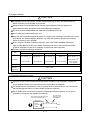
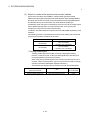
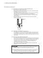
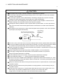
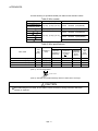
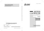
Do not mistake the direction of the surge absorbing diode
installed on the DC relay for the control signal output of
brake signals, etc. Incorrect installation may lead to signals
not being output when trouble occurs or the protective
functions not functioning.
Do not connect or disconnect the connection cables between
each unit, the encoder cable or PLC expansion cable while the
power is ON.
Servo amplifier
VIN
(24VDC)
Control output
signal
RA
Securely tighten the cable connector fixing screws and fixing mechanisms. Insufficient fixing
may lead to the cables combing off during operation.
Do not bundle the power line or cables.
(5) Trial operation and adjustment
!
CAUTION
Confirm and adjust the program and each parameter before operation. Unpredictable
movements may occur depending on the machine.
Extreme adjustments and changes may lead to unstable operation, so never make them.
When using the absolute position system function, on starting up, and when the Motion
controller or absolute value motor has been replaced, always perform a home position return.
A-7
(6) Usage methods
!
CAUTION
Immediately turn OFF the power if smoke, abnormal sounds or odors are emitted from the
Motion controller, servo amplifier or servomotor.
Always execute a test operation before starting actual operations after the program or
parameters have been changed or after maintenance and inspection.
The units must be disassembled and repaired by a qualified technician.
Do not make any modifications to the unit.
Keep the effect or electromagnetic obstacles to a minimum by installing a noise filter or by using
wire shields, etc. Electromagnetic obstacles may affect the electronic devices used near the
Motion controller or servo amplifier.
When using the CE Mark-compliant equipment, refer to the "EMC Installation Guidelines"
(data number IB(NA)-67339) for the Motion controllers and refer to the corresponding EMC
guideline information for the servo amplifiers, inverters and other equipment.
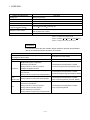
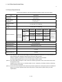
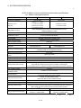
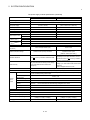
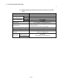
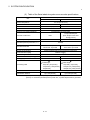
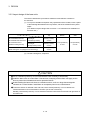
Use the units with the following conditions.
Item
Conditions
Q61P-A1
100 to 120VAC
Q61P-A2
+10%
-15%
200 to 240VAC
Q62P
+10%
-15%
Q63P
100 to 240VAC
+10%
-15%
24VDC
Q64P
+30%
-35%
100 to 120VAC
200 to 240VAC
Input power
(85 to 132VAC)
(170 to 264VAC)
(85 to 264VAC)
Input frequency
50/60Hz ±5%
Tolerable
momentary
power failure
20ms or less
(15.6 to 31.2VDC)
+10%
-15%
+10%
-15%
(85 to 132VAC/
170 to 264VAC)
(7) Corrective actions for errors
!
CAUTION
If an error occurs in the self diagnosis of the Motion controller or servo amplifier, confirm the
check details according to the instruction manual, and restore the operation.
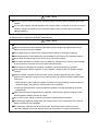
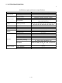
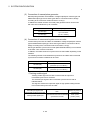
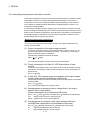
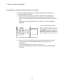
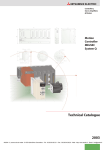
If a dangerous state is predicted in case of a power failure or product failure, use a servomotor
with electromagnetic brakes or install a brake mechanism externally.
Use a double circuit construction so that the electromagnetic brake operation circuit can be
operated by emergency stop signals set externally.
Shut off with servo ON signal OFF,
alarm, magnetic brake signal.
Servomotor
RA1
Electromagnetic
brakes
Shut off with the
emergency stop
signal(EMG).
EMG
24VDC
A-8
/
!
CAUTION
If an error occurs, remove the cause, secure the safety and then resume operation after alarm
release.
The unit may suddenly resume operation after a power failure is restored, so do not go near the
machine. (Design the machine so that personal safety can be ensured even if the machine
restarts suddenly.)
(8) Maintenance, inspection and part replacement
!
CAUTION
Perform the daily and periodic inspections according to the instruction manual.
Perform maintenance and inspection after backing up the program and parameters for the
Motion controller and servo amplifier.
Do not place fingers or hands in the clearance when opening or closing any opening.
Periodically replace consumable parts such as batteries according to the instruction manual.
Do not touch the lead sections such as ICs or the connector contacts.
Do not place the Motion controller or servo amplifier on metal that may cause a power leakage
or wood, plastic or vinyl that may cause static electricity buildup.
Do not perform a megger test (insulation resistance measurement) during inspection.
When replacing the Motion controller or servo amplifier, always set the new module settings
correctly.
When the Motion controller or absolute value motor has been replaced, carry out a home
position return operation using one of the following methods, otherwise position displacement
could occur.
1) After writing the servo data to the Motion controller using programming software, switch on
the power again, then perform a home position return operation.
2) Using the backup function of the programming software, load the data backed up before
replacement.
After maintenance and inspections are completed, confirm that the position detection of the
absolute position detector function is correct.
Do not short circuit, charge, overheat, incinerate or disassemble the batteries.
The electrolytic capacitor will generate gas during a fault, so do not place your face near the
Motion controller or servo amplifier.
The electrolytic capacitor and fan will deteriorate. Periodically replace these to prevent
secondary damage from faults. Replacements can be made by our sales representative.
A-9
(9) About processing of waste
When you discard Motion controller, servo amplifier, a battery (primary battery) and other option articles,
please follow the law of each country (area).
!
CAUTION
This product is not designed or manufactured to be used in equipment or systems in situations
that can affect or endanger human life.
When considering this product for operation in special applications such as machinery or
systems used in passenger transportation, medical, aerospace, atomic power, electric power, or
submarine repeating applications, please contact your nearest Mitsubishi sales representative.
Although this product was manufactured under conditions of strict quality control, you are
strongly advised to install safety devices to forestall serious accidents when it is used in facilities
where a breakdown in the product is likely to cause a serious accident.
(10) General cautions
!
CAUTION
All drawings provided in the instruction manual show the state with the covers and safety
partitions removed to explain detailed sections. When operating the product, always return the
covers and partitions to the designated positions, and operate according to the instruction
manual.
A - 10
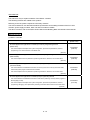
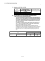
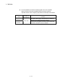
REVISIONS
The manual number is given on the bottom left of the back cover.
Print Date
Nov., 2001
May., 2002
Manual Number
Revision
IB(NA)-0300040-A First edition
IB(NA)-0300040-B [Addition model]
Q173CPUN/Q172CPUN, MR-J2M-B, A10BD-PCF
[Addition function]
• For Windows2000
• ROM operation
•MODE LED Installation mode/ROM writing mode
•BOOT LED Installation mode/ROM writing mode
[Partial correction]
Sep., 2003
IB(NA)-0300040-C [Addition model]
Q173CPUN-T/Q172CPUN-T, A31TU-D3K13/A31TU-DNK13,
Q172EX-S1, Q173PX-S1, Q64AD, Q68ADV, Q68ADI, Q62DA, Q64DA,
Q68DAV, Q68DAI, A6TBXY36, A6TBXY54, A6TBX70,
Q170TUD3CBL3M, Q170TUDNCBL3M, Q170TUDNCBL03M-A,
Q170TUTM, A31TUD3TM, FR-V5 0- , Software for SV43
[Addition function]
For WindowsXP, Home position return function
[Additional correction/partial correction]
Safety precautions, About processing of waste, Discard of internal
rechargeable battery, Instructions for installation of operation system
software, Troubleshooting, Precautions for air transportation of battery,
etc,
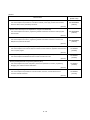
IB(NA)-0300040-D [Addition model]
Q62P, Q172EX-S2, Q172EX-S3, Q170ENC
[Additional correction/partial correction]
Safety precautions, Operating environment of personal computer, System
design circuit example, Operating system software installation procedure,
Warranty, Model code(1CT780 1XB780), etc.
Mar., 2006
Japanese Manual Number IB(NA)-0300021
This manual confers no industrial property rights or any rights of any other kind, nor does it confer any patent
licenses. Mitsubishi Electric Corporation cannot be held responsible for any problems involving industrial property
rights which may occur as a result of using the contents noted in this manual.
© 2001 MITSUBISHI ELECTRIC CORPORATION
A - 11
INTRODUCTION
Thank you for choosing the Q173CPU(N)/Q172CPU(N) Motion Controller.
Please read this manual carefully so that equipment is used to its optimum.
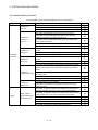
CONTENTS
Safety Precautions .........................................................................................................................................A- 1
Revisions ........................................................................................................................................................A-11
Contents .........................................................................................................................................................A-12
About Manuals ...............................................................................................................................................A-15
1. OVERVIEW
1- 1 to 1- 2
1.1 Overview................................................................................................................................................... 1- 1
2. SYSTEM CONFIGURATION
2- 1 to 2-100
2.1 Motion System Configuration .................................................................................................................. 2- 1
2.1.1 Q173CPU(N) System overall configuration...................................................................................... 2- 8
2.1.2 Q172CPU(N) System overall configuration...................................................................................... 2-10
2.1.3 Function explanation of the Q173CPU(N)/Q172CPU(N) Motion CPU modules ............................ 2-12
2.1.4 Restrictions on Motion systems........................................................................................................ 2-13
2.2 System Configuration Equipment............................................................................................................ 2-15
2.3 General Specifications ............................................................................................................................. 2-24
2.4 Specifications of Equipment and Settings............................................................................................... 2-26
2.4.1 Name of parts for CPU module ........................................................................................................ 2-26
2.4.2 Power supply module........................................................................................................................ 2-36
2.4.3 Base unit and extension cable.......................................................................................................... 2-43
2.4.4 Q172LX Servo external signals interface module............................................................................ 2-46
2.4.5 Q172EX Serial absolute synchronous encoder interface module................................................... 2-51
2.4.6 Q173PX Manual pulse generator interface module......................................................................... 2-61
2.4.7 Manual pulse generator/Serial absolute synchronous encoder ...................................................... 2-70
2.4.8 A31TU-D3 /A31TU-DN Teaching unit (Japanese version only) ................................................ 2-72
2.4.9 SSCNET cables, terminal connector and connection method ........................................................ 2-82
2.4.10 External battery ............................................................................................................................... 2-96
2.4.11 Cooling fan unit (Q170FAN) (Q173CPU/Q172CPU only) ............................................................. 2-99
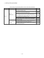
3. DESIGN
3- 1 to 3-20
3.1 System Designing Procedure .................................................................................................................. 3- 1
3.2 External Circuit Design ............................................................................................................................ 3- 4
3.2.1 Power supply circuit design .............................................................................................................. 3-12
3.2.2 Safety circuit design .......................................................................................................................... 3-13
3.3 Layout Design within The Control Panel ................................................................................................. 3-15
3.3.1 Installation environment .................................................................................................................... 3-15
3.3.2 Layout design of the base units ........................................................................................................ 3-16
3.3.3 Calculating heat generation by Motion controller............................................................................. 3-17
3.4 Design Checklist ...................................................................................................................................... 3-20
A - 12
4. INSTALLATION AND WIRING
4- 1 to 4-20
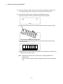
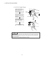
4.1 Module Installation ................................................................................................................................... 4- 1
4.1.1 Instructions for handling .................................................................................................................... 4- 1
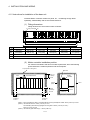
4.1.2 Instructions for installation of the base unit ...................................................................................... 4- 3
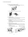
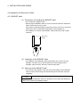
4.1.3 Installation and removal of module................................................................................................... 4- 5
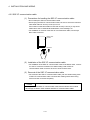
4.2 Installation and Removal of Cable........................................................................................................... 4- 7
4.2.1 SSCNET cable .................................................................................................................................. 4- 7
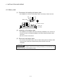
4.2.2 SSC I/F communication cable .......................................................................................................... 4- 8
4.2.3 Battery cable...................................................................................................................................... 4- 9
4.2.4 Cable for teaching unit ...................................................................................................................... 4-10
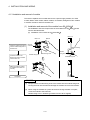
4.3 Installation of the Serial Absolute Synchronous Encoder....................................................................... 4-12
4.4 Replacement of the Cooling fan unit (Q170FAN) (Q173CPU/Q172CPU only)..................................... 4-14
4.5 Wiring........................................................................................................................................................ 4-15
4.5.1 Instructions for wiring ........................................................................................................................ 4-15
4.5.2 Wiring to the power supply module .................................................................................................. 4-18
4.6 Installation/Wiring Checklist..................................................................................................................... 4-19
5. TRIAL OPERATION AND ADJUSTMENT
5- 1 to 5- 8
5.1 Checklist before Trial Operation .............................................................................................................. 55.2 Trial Operation and Adjustment Procedure............................................................................................. 55.3 Operating System Software Installation Procedure................................................................................ 55.4 Trial Operation and Adjustment Checklist............................................................................................... 56. INSPECTION AND MAINTENANCE
1
2
7
8
6- 1 to 6-28
6.1 Maintenance Works ................................................................................................................................. 6- 2
6.1.1 Instruction of Inspection works ......................................................................................................... 6- 2
6.2 Daily Inspection ........................................................................................................................................ 6- 4
6.3 Periodic Inspection................................................................................................................................... 6- 6
6.4 External Battery........................................................................................................................................ 6- 7
6.4.1 Battery service life time ..................................................................................................................... 6- 8
6.4.2 Battery replacement procedure ........................................................................................................ 6- 9
6.5 Discard of internal rechargeable battery ................................................................................................. 6-11
6.6 Troubleshooting ....................................................................................................................................... 6-13
6.6.1 Basics of troubleshooting.................................................................................................................. 6-13
6.6.2 Troubleshooting of Motion CPU module and I/O modules .............................................................. 6-14
6.6.3 I/O modules troubleshooting............................................................................................................. 6-25
6.7 Confirm method of Error Code ................................................................................................................ 6-28
A - 13
APPENDICES
App- 1 to App-37
APPENDIX 1 Cables..................................................................................................................................App- 1
APPENDIX 1.1 SSCNET cables............................................................................................................App- 1
APPENDIX 1.2 Serial absolute synchronous encoder cable................................................................App-11
APPENDIX 1.3 Cable for the teaching unit ...........................................................................................App-14
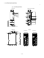
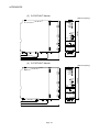
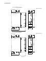
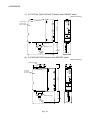
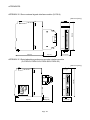
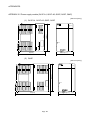
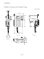
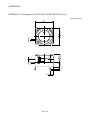
APPENDIX 2 Exterior Dimensions ............................................................................................................App-20
APPENDIX 2.1 CPU module .................................................................................................................App-20
APPENDIX 2.2 Servo external signals interface module (Q172LX) ....................................................App-24
APPENDIX 2.3 Serial absolute synchronous encoder interface module
(Q172EX/Q172EX-S1/Q172EX-S2/Q172EX-S3).......................................................App-24
APPENDIX 2.4 Manual pulse generator interface module (Q173PX/Q173PX-S1).............................App-25
APPENDIX 2.5 Power supply module (Q61P-A1, Q61P-A2, Q62P, Q63P, Q64P) ............................App-26
APPENDIX 2.6 Dividing unit (Q173DV), Battery unit (Q170BAT) ........................................................App-27
APPENDIX 2.7 Connector .....................................................................................................................App-28
APPENDIX 2.8 Manual pulse generator (MR-HDP01) .........................................................................App-33
APPENDIX 2.9 Serial absolute synchronous encoder (MR-HENC/Q170ENC) ..................................App-34
APPENDIX 2.10 Teaching unit (A31TU-D3 /A31TU-DN ) ..............................................................App-35
APPENDIX 2.11 Cooling fan unit (Q170FAN) (Q173CPU/Q172CPU only) ........................................App-36
A - 14
About Manuals
This manual is only to explain hardware of the Motion controller.
The following manuals are related to this product.
Referring to this list, please request the necessary manuals.
This User's Manual do not describes hardware specification and handling methods of the PLC CPU
modules, power supply modules, base unit and I/O module in details.
The above contents, refer to the QCPU User's Manual and Building Block I/O Module User's Manual.
Related Manuals
(1) Motion controller
Manual Number
(Model Code)
Manual Name
Q173CPU(N)/Q172CPU(N) Motion controller (SV13/SV22) Programming Manual
(Motion SFC)
This manual explains the Multiple CPU system configuration, performance specifications, functions,
IB-0300042
(1XB781)
programming, error codes and others of the Motion SFC.
(Optional)
Q173CPU(N)/Q172CPU(N) Motion controller (SV13/SV22) Programming Manual
(REAL MODE)
This manual explains the servo parameters, positioning instructions, device list, error list and others.
IB-0300043
(1XB782)
(Optional)
Q173CPU(N)/Q172CPU(N) Motion controller (SV22) Programming Manual
(VIRTUAL MODE)
This manual describes the dedicated instructions use to the synchronous control by virtual main shaft,
mechanical system program create mechanical module.
IB-0300044
(1XB783)
This manual explains the servo parameters, positioning instructions, device list, error list and others.
(Optional)
Q173CPU(N)/Q172CPU(N) Motion controller (SV43) Programming Manual
This manual describes the dedicated instructions to execute the positioning control by Motion program of
EIA language (G-code).
This manual explains the Multiple CPU system configuration, performance specifications, functions,
programming, debugging, servo parameters, positioning instructions device list and error list and others.
(Optional)
A - 15
IB-0300070
(1CT784)
(2) PLC
Manual Number
(Model Code)
Manual Name
QCPU User's Manual (Hardware Design, Maintenance and Inspection)
This manual explains the specifications of the QCPU modules, power supply modules, base modules,
extension cables, memory card battery and others.
SH-080483ENG
(13JR73)
(Optional)
QCPU User's Manual (Function Explanation, Program Fundamentals)
This manual explains the functions, programming methods and devices and others to create programs
with the QCPU.
SH-080484ENG
(13JR74)
(Optional)
QCPU User's Manual (Multiple CPU System)
This manual explains the functions, programming methods and cautions and others to construct the
Multiple CPU system with the QCPU.
SH-080485ENG
(13JR75)
(Optional)
QCPU (Q Mode)/QnACPU Programming Manual (Common Instructions)
This manual explains how to use the sequence instructions, basic instructions, application instructions and
micro computer program.
SH-080039
(13JF58)
(Optional)
QCPU (Q Mode)/QnACPU Programming Manual (PID Control Instructions)
SH-080040
(13JF59)
This manual explains the dedicated instructions used to exercise PID control.
(Optional)
QCPU (Q Mode)/QnACPU Programming Manual (SFC)
This manual explains the system configuration, performance specifications, functions, programming,
debugging, error codes and others of MELSAP3.
SH-080041
(13JF60)
(Optional)
I/O Module Type Building Block User's Manual
SH-080042
(13JL99)
This manual explains the specifications of the I/O modules, connector, connector/terminal block
conversion modules and others.
(Optional)
A - 16
1 OVERVIEW
1. OVERVIEW
1
1.1 Overview
This User's Manual describes the hardware specifications and handling methods of the
Motion Controller's Model Q173CPU(N)/Q172CPU(N) for the Q series PLC Multiple
CPU system.
The Manual also describes those items related to the specifications of the option
module for the Motion controller, Manual pulse generator, Synchronous encoder,
Teaching unit and cables.
In this manual, the following abbreviations are used.
Generic term/Abbreviation
Description
Q173CPU(N)/Q172CPU(N),
Q173CPUN/Q172CPUN/Q173CPUN-T/Q172CPUN-T/Q173CPU/Q172CPU
Motion CPU or Motion CPU module
Motion CPU module
Q172LX/Q172EX/Q173PX
Q172LX Servo external signals interface module/
(Note-1)
Q172EX(-S1/-S2/-S3) Serial absolute synchronous encoder interface module
/
or Motion module
Q173PX(-S1) Manual pulse generator interface module
MR-H-BN
Servo amplifier model MR-H BN
MR-J2-B
Servo amplifier model MR-J2S- B/MR-J2M-B/MR-J2- B/MR-J2-03B5
AMP or Servo amplifier
QCPU, PLC CPU
or PLC CPU module
Multiple CPU system
or Motion system
General name for "Servo amplifier model MR-H BN/MR-J2S- B/MR-J2M-B/
MR-J2- B/MR-J2-03B5, Vector inverter FREQROL-V500 series"
Qn(H)CPU
Abbreviation for "Multiple PLC system of the Q series"
Abbreviation for "CPU No.n (n= 1 to 4) of the CPU module for the Multiple CPU
CPUn
system"
Programming software package
General name for "MT Developer" and "GX Developer"
Operating system software
General name for "SW RN-SV Q "
Operating system software for conveyor assembly use (Motion SFC) :
SV13
SW6RN-SV13Q
Operating system software for automatic machinery use (Motion SFC) :
SV22
SW6RN-SV22Q
SV43
Operating system software for machine tool peripheral use: SW5RN-SV43Q
MT Developer
Abbreviation for Integrated start-up support software package "MT Developer"
GX Developer
Manual pulse generator
or MR-HDP01
Serial absolute synchronous encoder
or MR-HENC/Q170ENC
SSCNET
(Note-2)
Absolute position system
Cooling fan unit
Abbreviation for MELSEC PLC programming software package "GX Developer
(Version 6 or later)"
Abbreviation for "Manual pulse generator (MR-HDP01)"
Abbreviation for "Serial absolute synchronous encoder (MR-HENC/Q170ENC)"
High speed serial communication between Motion controller and servo amplifier
General name for "System using the servomotor and servo amplifier for absolute
position"
Cooling fan unit (Q170FAN)
1-1
1 OVERVIEW
Generic term/Abbreviation
Description
Dividing unit
Dividing unit (Q173DV)
Battery unit
Battery unit (Q170BAT)
A0BD-PCF
A10BD-PCF/A30BD-PCF SSC I/F board
SSC I/F communication cable
Abbreviation for "Cable for SSC I/F board/card"
Teaching Unit
A31TU-D3 /A31TU-DN
or A31TU-D3 /A31TU-DN
(Note-3)
Teaching unit
Abbreviation for "MELSECNET/H module/Ethernet module/CC-Link module/
Intelligent function module
Serial communication module"
Vector inverter (FR-V500)
Vector inverter FREQROL-V500 series
(Note-1) : Q172EX can be used in SV22.
(Note-2) : SSCNET: Servo System Controller NETwork
(Note-3) : Teaching unit can be used in SV13.
REMARK
For information about the each module, design method for program and parameter,
refer to the following manuals relevant to each module.
Item
Reference Manual
PLC CPU, peripheral devices for PLC program design, I/O modules
and intelligent function module
Operation method for MT Developer
Manual relevant to each module
Help of each software
• Multiple CPU system configuration
SV13/SV22
• Performance specification
Q173CPU(N)/Q172CPU(N) Motion controller
• Design method for common parameter
(SV13/SV22) Programming Manual (Motion SFC)
• Auxiliary and applied functions
• Design method for positioning control program in
the real mode
• Design method for positioning control parameter
SV22
(Virtual mode)
• Design method for mechanical system program
Q173CPU(N)/Q172CPU(N) Motion controller
(SV13/SV22) Programming Manual (REAL MODE)
Q173CPU(N)/Q172CPU(N) Motion controller
(SV22) Programming Manual (VIRTUAL MODE)
• Multiple CPU system configuration
• Performance specification
SV43
• Design method for common parameter
Q173CPU(N)/Q172CPU(N) Motion controller
• Design method for Motion program
(SV43) Programming Manual
• Motion dedicated PLC instruction
• Design method for positioning control parameter
1-2
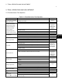
2 SYSTEM CONFIGURATION
2. SYSTEM CONFIGURATION
This section describes the Q173CPU(N)/Q172CPU(N) system configuration,
precautions on use of system and configured equipments.
2.1 Motion System Configuration
This section describes the equipment configuration, configuration with peripheral
devices and system configuration in the Q173CPU(N)/Q172CPU(N) system.
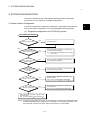
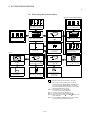
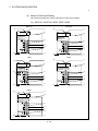
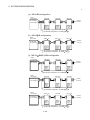
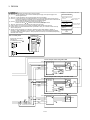
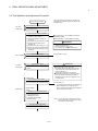
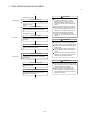
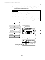
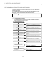
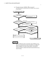
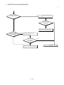
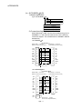
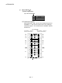
(1) Equipment configuration in Q173CPU(N) system
Q173CPU(N) System configuration
Is the teaching unit used?
YES
Use a Q173CPUN-T.
YES
Refer to equipment configuration of "(a) When using
the Dividing unit/external battery".
NO
(Note)
Is this system
continuously power off for 1000
hours or more running?
Note : Set the battery (A6BAT/MR-BAT) to the Dividing
unit (Q173DV).
NO
Should the
dividing unit be used to divide
SSCNET Lines?
YES
Refer to equipment configuration of "(a) When using
the Dividing unit/external battery".
NO
Refer to equipment configuration of "(a) When using
the Dividing unit/external battery".
NO
Is the type
of the amplifier used at 1st axis
of each SSCNET system
the same?
YES
Is only 1st
SSCNET system used?
YES
Refer to equipment configuration of "(b) When using
the Dividing cable".
Note : Use a Q173J2BCBL M/Q173HBCBL M.
YES
Refer to equipment configuration of "(b) When using
the Dividing cable".
Note : Use a Q173J2B2CBL M/Q173HB2CBL M.
NO
Is 1st and 2nd
SSCNET system used?
NO
Refer to equipment configuration of "(b) When using
the Dividing cable".
Note : Use a Q173J2B4CBL M/Q173HB4CBL M.
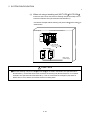
(Note) : Continuous power failure time which can be backed up on the internal rechargeable battery
is different depending on the charge time. It is possible to continuously power off for 1100
hours because of charge of 40 hours. Refer to the section 2.4.1(8) for details.
2-1
2
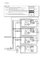
2 SYSTEM CONFIGURATION
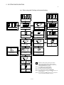
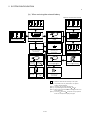
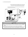
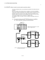
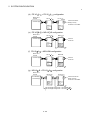
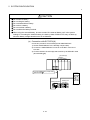
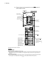
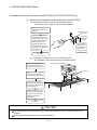
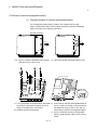
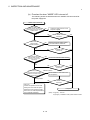
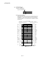
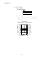
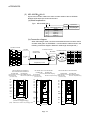
(a) When using the Dividing unit/external battery
Extension of the Q series module
Power supply module/
QCPU/ I/O module/ Intelligent
function module of the Q series
Motion module
(Q172LX, Q172EX, Q173PX)
Motion module
(Q172LX, Q172EX, Q173PX)
Extension cable
(QC B)
Q6 B extension base unit
(Q63B, Q65B, Q68B, Q612B)
Short-circuit connector for
the teaching unit
(Q170TUTM)
Power supply module/
I/O module/Intelligent function
module of the Q series
CPU base unit
(Q33B, Q35B, Q38B, Q312B)
(Note-5)
(Note-2)
Motion CPU module
(Q173CPU(N))
(Note-3)
(Note-5) (Note-6)
S VO ON
SSCNET cable
(Q173DVCBL M)
(Note-1)
Cable for the teaching unit
(Q170TUD CBL M(-A))
Teaching unit
(A31TU-D3 , A31TU-DN )
(Note-4)
SSCNET CN1 SSCNET CN3
MITSUBISHI
LITHIUM B ATTE RY
SSCNET CN2 SSCNET CN4
MITSUBISHI
LITHIUM BATTERY
Battery
(A6BAT/MR-BAT)
Q173CPU
Short-circuit connector for
the teaching unit
(A31TUD3TM)
Dividing unit
(Q173DV)
SSCNET cable
for MR-H-BN
SSCNET cable
for MR-J2 -B
(MR-J2HBUS M-A)
(MR-J2HBUS M)
It is possible to select the best according to the system.
(Note-1) : When using the external battery, be sure to set the
Battery(A6BAT/MR-BAT) to the Dividing unit(Q173DV).
Battery(A6BAT/MR-BAT) is optional.
(Note-2) : It is possible to use only Q173CPUN-T.
It is packed together with Q173CPUN-T.
(Note-3) : It varies by the connecting teaching unit.
(Note-4) : It is packed together with Q170TUD CBL M.
(Note-5) : When using the A31TU-D3 /A31TU-DN , be sure to use
the Q173CPUN-T.
(Note-6) : A31TU-D3 /A31TU-DN corresponds to only Japanese.
It does not correspond to display for English.
MITSUBISHI
Servo amplifier
(MR-H-BN)
Servo amplifier
(MR-J2 -B)
2-2
2 SYSTEM CONFIGURATION
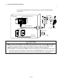
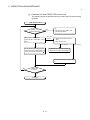
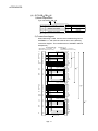
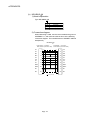
(b) When using the Dividing cable
Extension of the Q series module
Power supply module/
QCPU/ I/O module/ Intelligent
function module of the Q series
Motion module
(Q172LX, Q172EX, Q173PX)
Motion module
(Q172LX, Q172EX, Q173PX)
Extension cable
(QC B)
CPU base unit
(Q33B, Q35B, Q38B, Q312B)
(Note-4)
(Note-1)
Short-circuit connector for
the teaching unit
(Q170TUTM)
Motion CPU module
(Q173CPU(N))
Q6 B extension base unit
(Q63B, Q65B, Q68B, Q612B)
(Note-2)
Power supply module/
I/O module/Intelligent function
module of the Q series
(Note-4) (Note-5)
SV O ON
SSCNET cable
for MR-H-BN
SSCNET cable
for MR-J2 -B
Cable for the teaching unit
(Q170TUD CBL M(-A))
(Q173HB CBL M) (Q173J2B CBL M)
Teaching unit
(A31TU-D3 , A31TU-DN )
(Note-3)
MITSUBISHI
Servo amplifier
(MR-H-BN)
Short-circuit connector for the
teaching unit
(A31TUD3TM)
Servo amplifier
(MR-J2 -B)
It is possible to select the best according to the system.
(Note-1) : It is possible to use only Q173CPUN-T. It is packed
together with Q173CPUN-T.
(Note-2) : It varies by the connecting teaching unit.
(Note-3) : It is packed together with Q170TUD CBL M.
(Note-4) : When using the A31TU-D3 /A31TU-DN , be sure to use
the Q173CPUN-T.
(Note-5) : A31TU-D3 /A31TU-DN corresponds to only Japanese.
It does not correspond to display for English.
2-3
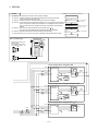
2 SYSTEM CONFIGURATION
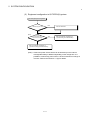
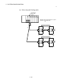
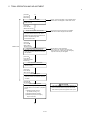
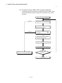
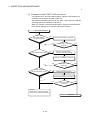
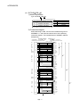
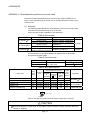
(2) Equipment configuration in Q172CPU(N) system
Q172CPU(N) System configuration
YES
Is the teaching unit used?
Use a Q172CPUN-T.
NO
(Note)
Is this system
continuously power off for 1000
hours or more running?
YES
Refer to equipment configuration of
"(a) When using the external battery".
NO
Refer to equipment configuration of
"(b) When not using the external battery".
(Note) : Continuous power off time which can be backed up on the internal
rechargeable battery is different depending on the charge time. It is
possible to continuously power off for 1100 hours because of charge of
40 hours. Refer to the section 2.4.1 (8) for details.
2-4
2 SYSTEM CONFIGURATION
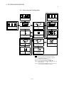
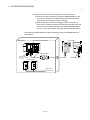
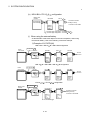
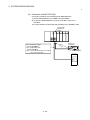
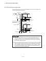
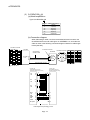
(a) When using the external battery
Extension of the Q series module
Power supply module/
QCPU/ I/O module/ Intelligent
function module of the Q series
Motion module
(Q172LX, Q172EX, Q173PX)
Motion module
(Q172LX, Q172EX, Q173PX)
CPU base unit
(Q33B, Q35B, Q38B, Q312B)
(Note-5)
Motion CPU module
(Q172CPU(N))
Extension cable
(QC B)
Q6 B extension base unit
(Q63B, Q65B, Q68B, Q612B)
Short-circuit connector for
the teaching unit
(Q170TUTM)
Power supply module/
I/O module/Intelligent function
module of the Q series
(Note-2)
(Note-1)
(Note-3)
BAT
(Note-5) (Note-6)
MITSUBISHI
S VO ON
LITHIUM BATTERY
CPU
PASSED
Q17BAT
DATE
Battery unit
(Q170BAT)
SSCNET cable
for MR-H-BN
SSCNET cable
for MR-J2 -B
Cable for the teaching unit
(Q170TUD CBL M(-A))
(Q172HBCBL -M) (Q172J2BCBL M-B)
Teaching unit
(A31TU-D3 , A31TU-DN )
(Note-4)
MITSUBISHI
MITSUBISHI
LITHIUM BATTERY
Battery
(A6BAT/MR-BAT)
Servo amplifier
(MR-H-BN)
Short-circuit connector for
the teaching unit
(A31TUD3TM)
Servo amplifier
(MR-J2 -B)
It is possible to select the best according to the system.
(Note-1) : When using the external battery, be sure to use the
SSCNET cable(Q172J2BCBL M-B/Q172HBCBL M-B)
and to set the battery (A6BAT/MR-BAT). Also install
the battery(A6BAT/MR-BAT)in the Battery unit(Q170BAT).
Battery(A6BAT/MR-BAT) is optional.
(Note-2) : It is possible to use only Q172CPUN-T.
It is packed together with Q172CPUN-T.
(Note-3) : It varies by the connecting teaching unit.
(Note-4) : It is packed together with Q170TUD CBL M.
(Note-5) : When using the A31TU-D3 /A31TU-DN , be sure to use
the Q172CPUN-T.
(Note-6) : A31TU-D3 /A31TU-DN corresponds to only Japanese.
It does not correspond to display for English.
2-5
2 SYSTEM CONFIGURATION
(b) When not using the external battery
Extension of the Q series module
Power supply module/
QCPU/ I/O module/ Intelligent
function module of the Q series
Motion module
(Q172LX, Q172EX, Q173PX)
Motion module
(Q172LX, Q172EX, Q173PX)
CPU base unit
(Q33B, Q35B, Q38B, Q312B)
Extension cable
(QC B)
(Note-4)
(Note-1)
Short-circuit connector for
the teaching unit
(Q170TUTM)
Motion CPU module
(Q172CPU(N))
Q6 B extension base unit
(Q63B, Q65B, Q68B, Q612B)
(Note-2)
Power supply module/
I/O module/Intelligent function
module of the Q series
(Note-4) (Note-5)
SVO ON
SSCNET cable
for MR-H-BN
SSCNET cable
for MR-J2 -B
(Q172HBCBL M)
Cable for the teaching unit
(Q170TUD CBL M(-A))
(Q172J2BCBL M)
Teaching unit
(A31TU-D3 , A31TU-DN )
(Note-3)
MITSUBISHI
Servo amplifier
(MR-H-BN)
Short-circuit connector for
the teaching unit
(A31TUD3TM)
Servo amplifier
(MR-J2 -B)
It is possible to select the best according to the system.
(Note-1) : It is possible to use only Q172CPUN-T. It is packed
together with Q172CPUN-T.
(Note-2) : It varies by the connecting teaching unit.
(Note-3) : It is packed together with Q170TUD CBL M.
(Note-4) : When using the A31TU-D3 /A31TU-DN , be sure to use
the Q172CPUN-T.
(Note-5) : A31TU-D3 /A31TU-DN corresponds to only Japanese.
It does not correspond to display for English.
2-6
2 SYSTEM CONFIGURATION
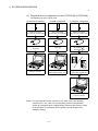
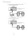
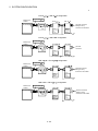
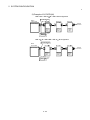
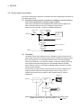
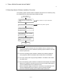
(3) Peripheral device configuration for the Q173CPU(N)/ Q172CPU(N)
The following (a) (b) (c) can be used.
(a) RS-232 configuration
(b) USB configuration
(c) SSCNET configuration
Motion CPU module
(Q173CPU(N), Q172CPU(N))
Motion CPU module
(Q173CPU(N), Q172CPU(N))
Motion CPU module
(Q173CPU(N), Q172CPU(N))
RS-232 cable
(QC30R2)
USB cable
SSC I/F communication cable
(Q170CDCBL M,
Q170BDCBL M)
MITSUBISHI
SSCNET
CARD
A30CD-PCF
Personal computer
Personal computer
(Windows 98/2000/XP only)
R
SSC I/F Card/Board
(A30CD-PCF/A 0BD-PCF)
Personal computer
(Note) : For information about GPP functions of PLC CPU, refer to the operating
manual of PLC. Also, refer to the programming manual of the operating
system for information about creating Motion programs, and refer to the help
of each software for information about operation of each programming
software package.
2-7
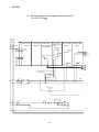
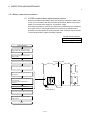
2 SYSTEM CONFIGURATION
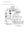
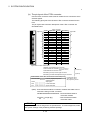
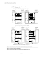
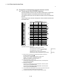
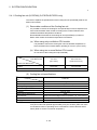
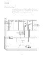
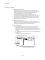
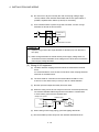
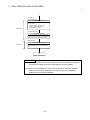
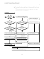
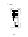
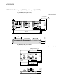
2.1.1 Q173CPU(N) System overall configuration
Q61P-A
Manual pulse
generator
interface module
PLC CPU/
Motion CPU
Synchronous
encoder
interface module
CPU base
unit
(Q3 B)
Servo external
signals
interface module
Motion CPU control module
Qn(H) Q173 Q172LX Q172EX Q172PX QI60
CPU CPU(N)
QX
Q6 AD
QY
Q6 DA I/O module of the Q Series or
Special function module
100/200VAC
(Note-2)
Analogue input/output
Personal Computer
IBM PC/AT
Input/output (Up to 256 points)
Dividing unit
(Q173DV)
USB/RS-232
Interrupt signals (16 points)
MITSUBISHI
LITHIUM BATTERY
P
Manual pulse generator 3/module
(MR-HDP01) (Up to 1 module)
Serial absolute synchronous encoder cable
(MR-JHSCBL M-H/Q170ENCCBL M)
Teaching unit (Note-1)
A31TU-D3 /A31TU-DN
Serial absolute synchronous encoder 2/module
(MR-HENC/Q170ENC) (Up to 6 modules)
E
Cable for the teaching
unit
(Q170TUD CBL M(-A))
External input signals
SSC I/F
Communication
cable
(Q170CDCBL M/
Q170BDCBL M)
SSC I/F Card/Board
(A30CD-PCF/A 0BD-PCF)
Number of Inputs
FLS
: Upper stroke limit
RLS
: Lower stroke limit
STOP
: Stop signal
DOG/CHANGE : Proximity dog/
Speed-position switching
SSCNET cable
8 axes/module
(Up to 4 modules)
SSCNET SYSTEM4
SSCNET SYSTEM3
SSCNET SYSTEM2
Terminal
connector
Terminal
connector
Panel Personal Computer
(WinNT/Win98/Win2000/WinXP)
Computer link SSC
Extension
cable
Power supply
module
Extension base unit
(Q6 B)
d1
SSCNET SYSTEM1
M
E
d1
d8
M
E
M
E
Terminal
connector
d8
M
E
d1
M
E
Terminal
connector
d8
M
E
d8
d1
M
E
M
E
MR-H BN/MR-J2S- B/MR-J2M-B/MR-J2- B/MR-J2-03B5 model
Servo amplifier, Vector inverter(FR-V500), Up to 32 axes
UP to 7 extensions
(Note-1) : Be sure to use the Q173CPUN-T.
A31TU-D3 /A31TU-DN corresponds to only Japanese.
It does not correspond to display for English.
(Note-2) : QI60 can be used in SV13/SV22.
2-8
2 SYSTEM CONFIGURATION
CAUTION
Construct a safety circuit externally of the Motion controller or servo amplifier if the abnormal
operation of the Motion controller or servo amplifier differ from the safety directive operation in the
system.
The ratings and characteristics of the parts (other than Motion controller, servo amplifier and
servomotor) used in a system must be compatible with the Motion controller, servo amplifier and
servomotor.
Set the parameter values to those that are compatible with the Motion controller, servo amplifier,
servomotor and regenerative resistor model and the system application. The protective functions may
not function if the settings are incorrect.
When a teaching unit is used, the cable for the teaching unit is necessary between the Motion CPU
(Q173CPUN-T/Q172CPUN-T) and teaching unit. And, connect the short-circuit connector for teaching
unit, after removing the teaching unit or when not using it.
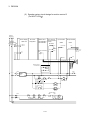
2-9
2 SYSTEM CONFIGURATION
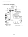
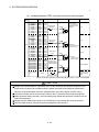
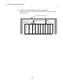
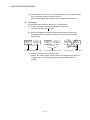
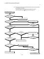
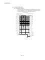
2.1.2 Q172CPU(N) System overall configuration
Q61P-A
Manual pulse
generator
interface module
PLC CPU/
Motion CPU
Synchronous
encoder
interface module
CPU base
unit
(Q3 B)
Servo external
signals
interface module
Motion CPU control module
Qn(H) Q172 Q172LX Q172EX Q172PX QI60
CPU CPU(N)
QX
Q6 AD
QY
Q6 DA I/O module of the Q Series or
Special function module
100/200VAC
(Note-2)
Analogue input/output
Battery unit
(Q170BAT)
Input/output (Up to 256 points)
MITSUBISHI
LITHIUM BATTERY
Interrupt signals (16 points)
Personal Computer
IBM PC/AT
P
USB/RS-232
Serial absolute synchronous encoder cable
(MR-JHSCBL M-H/Q170ENCCBL M)
Serial absolute synchronous encoder 2/module
(MR-HENC/Q170ENC) (Up to 4 modules)
E
Teaching unit (Note-1)
A31TU-D3 /A31TU-DN
External input signals
SSC I/F Card/Board
(A30CD-PCF/A 0BD-PCF)
Panel Personal Computer
(WinNT/Win98/Win2000/WinXP)
Computer link SSC
Extension
cable
8 axes/module
(Up to 1 module)
Terminal
connector
SSCNET cable
d1
SSCNET SYSTEM1
d2
d3
d8
M
M
M
M
E
E
E
E
MR-H BN/MR-J2S- B/MR-J2M-B/MR-J2- B/
MR-J2-03B5 model Servo amplifier,
Vector inverter(FR-V500), Up to 8 axes
Power supply
module
Extension base unit
(Q6 B)
Number of Inputs
FLS
: Upper stroke limit
RLS
: Lower stroke limit
STOP
: Stop signal
DOG/CHANGE : Proximity dog/
Speed-position switching
Cable for the teaching
unit
(Q170TUD CBL M(-A))
SSC I/F
Communication
cable
(Q170CDCBL M/
Q170BDCBL M)
Manual pulse generator 3/module
(MR-HDP01) (Up to 1 module)
(Note-1) : Be sure to use the Q172CPUN-T.
A31TU-D3 /A31TU-DN corresponds to only Japanese.
It does not correspond to display for English.
UP to 7 extensions
(Note-2) : QI60 can be used in SV13/SV22.
2 - 10
2 SYSTEM CONFIGURATION
CAUTION
Construct a safety circuit externally of the Motion controller or servo amplifier if the abnormal
operation of the Motion controller or servo amplifier differ from the safety directive operation in the
system.
The ratings and characteristics of the parts (other than Motion controller, servo amplifier and
servomotor) used in a system must be compatible with the Motion controller, servo amplifier and
servomotor.
Set the parameter values to those that are compatible with the Motion controller, servo amplifier,
servomotor and regenerative resistor model and the system application. The protective functions may
not function if the settings are incorrect.
When a teaching unit is used, the cable for the teaching unit is necessary between the Motion CPU
(Q173CPUN-T/Q172CPUN-T) and teaching unit. And, connect the short-circuit connector for teaching
unit, after removing the teaching unit or when not using it.
2 - 11
2 SYSTEM CONFIGURATION
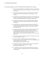
2.1.3 Function explanation of the Q173CPU(N)/Q172CPU(N) Motion CPU modules
(1) Up to 32 axes servo amplifiers per 4 systems (up to 8 axes per 1 system) can be
used in Q173CPU(N). Up to 8 axes servo amplifiers per 1 system can be used in
Q172CPU(N).
(2) It is possible to set the program which synchronized with the motion operation
cycle and executed at fixed cycle (0.88[ms], 1.77[ms], 3.55[ms], 7.11[ms],
14.2[ms]).
(3) It is possible to execute a download of servo parameters to servo amplifier, servo
ON/OFF to servo amplifier and position commands, etc. by connecting between
the Q173CPU(N)/Q172CPU(N) and servo amplifier with SSCNET cable.
(4) It is possible to select the servo control functions/programming languages by
installing the corresponding operating system software in the Q173CPU(N)/
Q172CPU(N).
(5) It is possible to use the signals such as stroke limit signals and synchronous
encoder connected to various Motion modules for motion control by setting the
Q173CPU(N)/Q172CPU(N) as the control CPU of various motion modules
(Q172LX/Q172EX, etc.).
(6) It is possible to execute not only servo control but also DI/O input/output control
according to programs described in Motion SFC program by setting the
Q173CPU(N)/Q172CPU(N) as the control CPU of Q series PLC I/O modules
(When the Motion SFC is used as the operating system software.).
(Refer to Section 2.2 (2) for Q series PLC I/O modules that can be controlled by
Motion CPU.)
(7) It is possible to exchange a data among CPUs such as automatic refresh, as the
Q series PLC Multiple CPU system.
(8) There is no restriction for installation position of Q172LX/Q173PX(-S1)/
Q172EX(-S1) among modules controlled by Motion CPU. The installation position
of Q172EX-S2/S3 is only CPU base unit.
Set the installation position in the system settings.
(9) It is possible to change a servo program, monitor or execute JOG operation by
connecting the teaching unit (A31TU-D3 /A31TU-DN ).
(Q173CPUN-T/Q172CPUN-T only).
(10) It is possible to execute the high-resolution (262144[PLS/rev]) synchronous
control by connecting the serial absolute synchronous encoder (Q170ENC) to
Q172EX-S2/S3.
2 - 12
2 SYSTEM CONFIGURATION
2.1.4 Restrictions on Motion systems
(1) It is not allowed to use the Motion CPU as the control CPU of a module installed
on the QA1S6 B extension base unit. PLC CPU must be used as the control
CPU.
(2) The connector for installation of memory card on the Motion CPU module is for
future function expansion.
(3) Motion CPU module cannot be used as standalone module. It must always be
used in combination with the PLC CPU module (version that supports Multiple
CPU systems). Moreover, it must be installed on the right side of PLC CPU
module. PLC CPU module cannot be installed in a position to the right of Motion
CPU module.
(4) Personal computer CPU unit must be installed on the right side of Motion CPU
module. Motion CPU module cannot be installed in a position to the right of
personal computer CPU unit.
(5) Make sure to use the PLC CPU module in "Q mode".
(6) Motion CPU module cannot be set as the control CPU of intelligent function
module or Graphic Operation Terminal (GOT).
(7) SSCNET cable which connects the Motion CPU and servo amplifier, and the
teaching unit connecting cable which connects the Motion CPU and A31TU(Note-1)
D3 /A31TU-DN
are pulled from the bottom part of unit. Make sure to
secure sufficient space for pulling out the cable when designing the control panel.
(8) Motion CPU module is one module element of Q series multiple PLC system. It
must be set the parameters of Q series multiple PLC system for each PLC CPU.
Motion CPU module must also be set to support the Multiple CPU system in the
system settings.
(9) Make sure to use the Motion CPU as the control CPU of motion modules
(Note-2)
dedicated for Motion CPU (Q172LX, Q172EX
, Q173PX, etc.). They will not
operate correctly if PLC CPU is set and installed as the control CPU by mistake.
Motion CPU is treated as a 32-point intelligent module by PLC CPU of other CPU.
It cannot be accessed from other CPU.
(10) When a Multiple CPU system is configured, make sure to configure the modules
so that the total current consumption of individual modules on the CPU base does
not exceed the 5VDC output capacity of power supply module.
(Refer to Section 2.4.2 (3), (4) "Selection of the power supply module".)
(Note-2)
(11) Installation position of the Q172EX-S2/S3
is only CPU base unit.
(Note-1) : Teaching unit can be used in SV13. It cannot be used in SV22/SV43.
(Note-2) : Q172EX can be used in SV22. It cannot be used in SV13/SV43.
2 - 13
2 SYSTEM CONFIGURATION
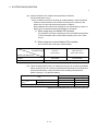
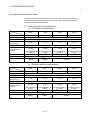
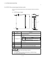
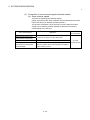
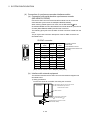
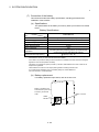
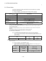
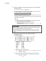
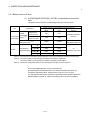
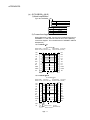
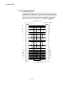
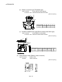
(12) Number of Motion CPU modules and temperature conditions
(Q173CPU/Q172CPU only)
(a) It is possible to remove the Cooling fan unit(Q170FAN) in order to disperse
heat from inside the Motion CPU module according to the number of the
Motion CPU module and ambient temperature conditions.
Removable/Not removable of the Cooling fan unit (Q170FAN) by number of
Motion CPU modules and ambient temperature is as follows.
1) When using only one Motion CPU module
It is possible to remove the Cooling fan unit if the ambient temperature
in which the Motion CPU module will be operating is 0 to 40°C (32 to
104°F).
2) When using two or more Motion CPU modules
Do not remove the Cooling fan unit(Q170FAN).
Ambient temperature
of the Motion CPU
0 to 40°C
(32 to 104°F)
Over 40 to 55°C
(Over 104 to 131°F)
Removable
Not removable
Number of the Motion CPU
1 module
2 modules or more
Not removable
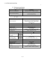
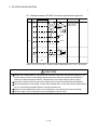
(13) When the backup time (when it is charged for 40 hours) for internal rechargeable
battery of Motion CPU is 1100 hours (Guaranteed time)/4300 hours (Actual time).
Set the external battery if the power failure time exceeds guaranteed time.
(Refer to Section 2.4.10 External battery)
Continuous power failure time [h]
Item
Internal rechargeable
(Note)
battery
Guaranteed time (MIN)
Actual time (TYP)
Charging time: 8 hours or more
200
500
Charging time: 40 hours or more
1100
4300
60000
240000
External battery
(Note):Internal rechargeable battery is charged while power ON.
2 - 14
2 SYSTEM CONFIGURATION
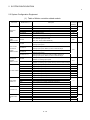
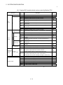
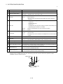
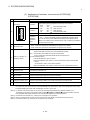
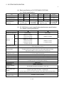
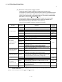
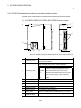
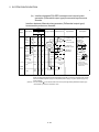
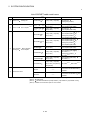
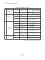
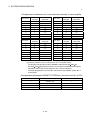
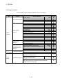
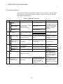
2.2 System Configuration Equipment
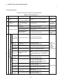
(1) Table of Motion controller related module
Part name
Motion CPU
module
Servo external
signals
interface module
Serial absolute
synchronous
encoder
interface module
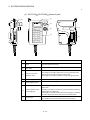
Manual pulse
generator
interface module
Model name (Note-1)
Description
Current
consumption Remark
5VDC[A]
Q172CPUN
Up to 8 axes control
1.14
Q172CPUN-T
Up to 8 axes control, For teaching unit
1.45
Q172CPU
Up to 8 axes control, With cooling fan unit
1.62
Q173CPUN
Up to 32 axes control
1.25
Q173CPUN-T
Up to 32 axes control, For teaching unit
1.56
Q173CPU
Up to 32 axes control, With cooling fan unit
1.75
Q172LX
Servo external signal input 8 axes
(FLS, RLS, STOP, DOG/CHANGE×8)
0.05
Q172EX
Serial absolute synchronous encoder MR-HENC interface×2,
Tracking input 2 points
Q172EX-S1 (Note-2)
Serial absolute synchronous encoder MR-HENC interface×2,
Tracking input 2 points, Memory built-in for data exchange
Q172EX-S2
Serial absolute synchronous encoder Q170ENC interface×2,
Tracking input 2 points
Q172EX-S3 (Note-2)
Serial absolute synchronous encoder Q170ENC interface×2,
Tracking input 2 points, Memory built-in for data exchange
Q173PX
Manual pulse generator MR-HDP01/Incremental synchronous encoder
interface ×3, Tracking input 3 points
Q173PX-S1 (Note-2)
Manual pulse generator MR-HDP01/Incremental synchronous encoder
interface ×3, Tracking input 3 points, Memory built-in for data exchange
Q00CPU
Program capacity 8k steps
0.25
Q01CPU
Program capacity 14k steps
0.27
Q02CPU
0.07
0.11
Program capacity 28k steps
0.60
PLC CPU module Q02HCPU
Program capacity 28k steps
0.64
Q06HCPU
Program capacity 60k steps
0.64
Power supply
module (Note-3)
CPU base unit
Extension base
unit
Q12HCPU
Program capacity 124k steps
0.64
Q25HCPU
Program capacity 252k steps
0.64
Q61P-A1
100 to 120VAC input, 5VDC 6A output
Q61P-A2
200 to 240VAC input, 5VDC 6A output
Q62P
100 to 240VAC input, 5VDC 3A/24VDC 0.6A output
Q63P
24VDC input, 5VDC 6A output
Q64P
100 to 120VAC/200 to 240VAC input, 5VDC 8.5A output
Q33B
Number of I/O modules installed 3 slots
0.105
Q35B
Number of I/O modules installed 5 slots
0.110
Q38B
Number of I/O modules installed 8 slots
0.114
Q312B
Number of I/O modules installed 12 slots
0.121
Q63B
Number of I/O modules installed 3 slots
0.105
Q65B
Number of I/O modules installed 5 slots
0.110
Q68B
Number of I/O modules installed 8 slots
0.114
Q612B
Number of I/O modules installed 12 slots
0.121
2 - 15
——
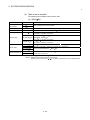
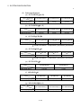
2 SYSTEM CONFIGURATION
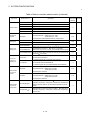
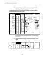
Table of Motion controller related module (continued)
Part name
Extension cable
Manual pulse
generator
Teaching unit
Cable for the
teaching unit
Short-circuit
connector for
teaching unit
Model name (Note-1)
QC05B
Length 0.45m(1.48ft.)
QC06B
Length 0.6m(1.97ft.)
QC12B
Length 1.2m(3.94ft.)
QC30B
Length 3m(9.84ft.)
QC50B
Length 5m(16.40ft.)
QC100B
Length 10m(32.81ft.)
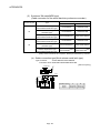
MR-HDP01
Pulse resolution: 25PLS/rev(100PLS/rev after magnification by 4)
Permitted axial loads Radial load: Up to 19.6N
Thrust load: Up to 9.8N
Permitted speed: 200r/min(Normal rotation), Voltage output
Current
consumption Remark
5VDC[A]
——
0.06
A31TU-D3K13
For SV13, With 3-position deadman switch, Only Japanese
A31TU-DNK13
For SV13, Without deadman switch, Only Japanese
Q170TUD3CBL3M
Q173CPUN-T/Q172CPUN-T
A31TU-D3 , 3m(9.84ft.)
(Attachment: Short-circuit connector (A31TUD3TM) for teaching unit)
——
Q170TUDNCBL3M
Q173CPUN-T/Q172CPUN-T
A31TU-DN , 3m(9.84ft.)
(Attachment: Short-circuit connector (A31TUD3TM) for teaching unit)
——
Q170TUDNCBL03M-A
Exchange cable for direct connection Q173CPUN-T/Q172CPUN-T
A31TU-DN , 0.3m(0.98ft.)
——
Q170TUTM
Short-circuit connector for teaching unit for direct connection to
Q173CPUN-T/Q172CPUN-T
It is packed together with Q173CPUN-T/Q172CPUN-T.
——
A31TUD3TM
Short-circuit connector for teaching unit for connection to connect with
Q170TUD3CBL3M/Q170TUDNCBL3M
It is packed together with Q170TUD3CBL3M/Q170TUDNCBL3M.
——
MR-HENC
Resolution: 16384PLS/rev
Permitted axial loads Radial load: Up to 98N
Thrust load: Up to 49N
Permitted speed: 4300r/min
0.15
Q170ENC
Resolution: 262144PLS/rev
Permitted axial loads Radial load: Up to 19.6N
Thrust load: Up to 9.8N
Permitted speed: 3600r/min
0..20
MR-JHSCBL M-H
Q172EX
Serial absolute synchronous encoder
2m(6.56ft.), 5m(16.40ft.), 10m(32.81ft.), 20m(65.62ft.), 30m(98.43ft.)
(Same as encoder cables for HC-SFS/RFS/UFS(2000r/min) series
motors)
Serial absolute
synchronous
encoder
Serial absolute
synchronous
encoder cable
Description
Q170ENCCBL M
Q172EX-S2/-S3
Serial absolute synchronous encoder Q170ENC
2m(6.56ft.), 5m(16.40ft.), 10m(32.81ft.), 20m(65.62ft.), 30m(98.43ft.),
50m(164.04ft.)
2 - 16
0.26
——
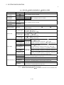
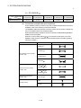
2 SYSTEM CONFIGURATION
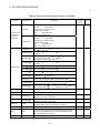
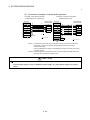
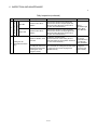
Table of Motion controller related module (continued)
Part name
Model name (Note-1)
Description
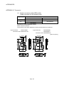
MR-J2CNS
Q172EX(-S1) side connector
Connector
:10120-3000VE
Connector case : 10320-52F0-008
MR-HENC side connector
Plug
: MS3106B20-29S
Cable clump : MS3057-12A
Q170ENCCNS
Q172EX-S2/-S3 side connector
Connector
:10120-3000VE
Connector case : 10320-52F0-008
Q170ENC side connector
Plug
: MS3106B22-14S
Cable clump : MS3057-12A
Q172HBCBL M
• Q172CPU(N)
Servo amplifier (MR-H BN)
• MR-H BN
FR-V5NS (Note-5)
Q172HBCBL M-B
Q172CPU(N)
(Q170BAT)
Q172J2BCBL M
Servo amplifier (MR-J2 -B) (Note-4)
• Q172CPU(N)
• Servo amplifier (MR-J2 -B) (Note-4)
FR-V5NS (Note-5)
(Note-5)
• Dividing unit (Q173DV)
FR-V5NS
Q172J2BCBL M-B
Q172CPU(N)
(Q170BAT)
Connector set for
serial absolute
synchronous
encoder cable
Q173HB
CBL M Q173CPU(N)
Q173J2B
CBL M Q173CPU(N)
SSCNET cable
Current
consumption Remark
5VDC[A]
——
Servo amplifier (MR-H BN) and Battery unit
Servo amplifier (MR-J2 -B) (Note-4) and Battery unit
Servo amplifier (MR-H BN)
Servo amplifier MR-J2 -B (Note-4)
Q173DVCBL M
Q173CPU(N)
FR-V5NSCBL
• Q172CPU(N)
FR-V5NS (Note-5)
(Note-5)
• FR-V5NS
FR-V5NS (Note-5)
MR-HBUS M
Servo amplifier (MR-H BN)
MR-J2HBUS M-A
• Servo amplifier (MR-H BN)
• Servo amplifier (MR-H BN)
MR-J2HBUS M
• Servo amplifier (MR-J2 -B) (Note-4)
• Servo amplifier (MR-J2 -B) (Note-4)
SSC I/F board
A30BD-PCF
ISA bus loading type, 2ch/board
SSC I/F card
A30CD-PCF
PCMCIA TYPE II, 1ch/card
——
Dividing unit(Q173DV)
Servo amplifier (MR-H BN)
Servo amplifier (MR-J2 -B) (Note-4)
Dividing unit (Q173DV)
Servo amplifier (MR-J2 -B)(Note-4)
Dividing unit (Q173DV)
——
Cable for SSC I/F
Q170BDCBL M
board
Q173CPU(N)/Q172CPU(N)
SSC I/F board
3m(9.84ft.), 5m(16.40ft.), 10m(32.81ft.)
Cable for SSC I/F
Q170CDCBL M
card
Q173CPU(N)/Q172CPU(N)
SSC I/F card
3m(9.84ft.), 5m(16.40ft.), 10m(32.81ft.)
Dividing unit
Q173DV
For dividing the SSCNET systems of Q173CPU(N) into 4.
(Attachment: Battery holder for IC-RAM memory backup)
——
Battery unit
Q170BAT
For IC-RAM memory backup of Q172CPU(N)
——
Battery
A6BAT
For IC-RAM memory backup of Q173CPU(N)/Q172CPU(N) module
(Motion SFC programs(SV13/SV22), Servo programs(SV13/SV22),
Motion programs(SV43), Parameters)
——
Cooling fan unit
Q170FAN
Cooling fan of the Motion CPU module
0.08
2 - 17
2 SYSTEM CONFIGURATION
Table of Motion controller related module (continued)
Part name
Q172CPU(N)
connector set
Q173CPU(N)
connector set
Q173DV
connector set
Model name (Note-1)
Description
Current
consumption Remark
5VDC[A]
Q172CON
Connector for Q172CPU(N) (Note-6)
Connector : HDR-E14MG1
Case
: HDR-E14LPA5
——
Q173CON
Q173CPU(N) side connector set (Note-6)
Connector : HDR-E26MG1
Case
: HDR-E26LPA5
——
Q173DVCON
Q173CPU(N) side connector set (Note-6)
Connector : HDR-E26MG1
Case
: HDR-E26LPA5
Q173DV side connector set
Connector : 10126-3000VE
Case
: 10326-52F0-008
——
A6TBXY36
For positive common sink type input module, sink type output module
(standard type)
Connector/terminal
block conversion
A6TBXY54
module
For positive common sink type input module, sink type output module (2wire type)
A6TBX70
For positive common sink type input module (3-wire type)
AC05TB
Length 0.5m (1.64ft.)
AC10TB
Cable for
AC20TB
connector/terminal
AC30TB
block conversion
AC50TB
module
AC80TB
AC100TB
——
Length 1m (3.28ft.)
Length 2m (6.56ft.)
——
Length 3m (9.84ft.)
Length 5m (16.40ft.)
Length 8m (26.25ft.)
Length 10m(32.81ft.)
(Note-1) :
=Number of systems (none: 1 system, 2: 2 systems, 4: 4 systems)
=Cable length (05: 0.5m(1.64ft.), 1: 1m(3.28ft.), 2: 2m(6.56ft.), 3: 3m(9.84ft.), 5: 5m(16.40ft.), 10: 10m(32.81ft.),
20: 20m(65.62ft.), 30: 30m(98.43ft.))
(Note-2) : Q172EX-S1 and Q173PX-S1 can be used is only the operating system software of special specification that
needs data exchange function.
(Note-3) : Be sure to use the power supply module within the range of power supply capacity.
(Note-4) : MR-J2S- B/MR-J2M-B/MR-J2- B/MR-J2-03B5 type servo amplifier
(Note-5) : SSCNET communication option for vector inverter
(Note-6) : Crimping terminal is not sold in Mitsubishi. The following jig is requested to be procured by customers.
Specified tool (Honda Connectors make) : FHAT-0029/FHPT-0004C
2 - 18
2 SYSTEM CONFIGURATION
(2) Q series PLC module which can be control by Motion CPU
Part name
AC
Input
module
DC
Contact output
module
Output
module
Transistor
Sink Type
Model
name
Input/Output
DC Input/
composite
Transistor output
module
Interrupt module
Analogue module
Remark
QX10
100-120VAC, 7-8mA, 16 points, Terminal block
QX40
24VDC/4mA, Positive common, 16 points, Terminal block
QX41
24VDC/4mA, Positive common, 32 points, Connector
QX42
24VDC/4mA, Positive common, 64 points, Connector
QX70
12VDC/5V, Positive common/Negative common shared, 16 points,
Terminal block
QX71
12VDC/5V, Positive common/Negative common shared, 32 points,
Terminal block
QX72
12VDC/5V, Positive common/Negative common shared, 64 points,
Terminal block
QX80
24VDC/4mA, Negative common, 16 points, Terminal block
QX81
24VDC/4mA, Negative common, 32 points, Connector
QY10
240VAC/24VDC, 2A/point, 8A/common, 16 points/common, Terminal block
QY40P
12V/24VDC, 0.1A/point, 1.6A/common, 16 points/common Terminal block
QY41P
12V/24VDC, 0.1A/point, 2A/common, 32 points/common Connector
QY42P
12V/24VDC, 0.1A/point, 2A/common, 64 points(32 points/common),
Connector
QY50
12V/24VDC, 0.5A/point, 4A/common, 16 points(16 points/common),
Terminal block
QY80
12V/24VDC, 0.5A/point, 4A/common, 16 points(16 points/common),
Terminal block
QY81P
12V/24VDC, 0.1A/point, 2A/common, 32 points(32 points/common),
Connector
Source Type
TTL•CMOS(Sink)
Description
QY70
5/12VDC, 16mA/point, 16 points(16 points/common), Terminal block
QY71
5/12VDC, 16mA/point, 32 points(32 points/common), Connector
QH42P
24VDC Positive common: 32 points
DC12-24V/0.1A Output Sink type: 32 points, Connector,
Provided (Thermal protectors, protector against short circuit)
QX48Y57
24VDC Positive common: 8 points
DC12-24V/0.5A Output Sink type: 7 points, Terminal block,
Provided (When face is broken, LED lights and signal is output to CPU)
QI60
DC24V/4mA, Positive common, 16 points, Terminal block
Q64AD
4ch, A/D conversion, Voltage • Current input
Q68ADV
8ch, A/D conversion, Voltage input
Q68ADI
8ch, A/D conversion, Current input
Q62DA
2ch, D/A conversion, Voltage • Current output
Q64DA
4ch, D/A conversion, Voltage • Current output
Q68DAV
8ch, D/A conversion, Voltage output
Q68DAI
8ch, D/A conversion, Current output
Marked "
2 - 19
": connectors are not provided.
2 SYSTEM CONFIGURATION
(3) Table of servo amplifier
The following servo amplifier series can be used.
(a) MR-H BN
Part name
MR-H series
servo amplifier
Model name
MR-H BN
MR-H
KBN
Description
Refer to catalogue of the servo amplifier.
Battery
MR-BAT
Back-up for the absolute position detection
Terminal connector
MR-TM
Connected to the last servo amplifier (MR-H BN) by SSCNET.
MR-HBUS M
MR-H BN
MR-H BN
0.5m(1.64ft.), 1m(3.28ft.), 5m(16.40ft.)
SSCNET cable
MR-H BN
• Q173DV
MR-J2HBUS M-A • MR-H BN
MR-J2 -B (Note-1)
0.5m(1.64ft.), 1m(3.28ft.), 5m(16.40ft.)
Q172HBCBL M
MR-H BN
FR-V5NS (Note-2)
0.5m(1.64ft.), 1m(3.28ft.), 5m(16.40ft.)
HA-LH K, HC-SF/RF/UF(2000r/min) series motor
MR-H BN
MR-EN1CBL M-H 2m(6.56ft.), 5m(16.40ft.), 10m(32.81ft.), 20m(65.62ft.), 30m(98.43ft.)
MR-HSCBL M
Encoder cable
MR-JCCBL M-L
MR-JCCBL M-H
Encoder connector set
MR-JSCNS
MR-EN1CNS
HA-FF, HC-MF/UF(3000r/min)
MR-H BN
Servo amplifier side connector for HA-LH K, HC-SF/RF/UF(2000r/min) series motor,
Encoder side connector set
(Note-1) : MR-J2S- B/MR-J2M-B/MR-J2- B/MR-J2-03B5 type servo amplifier
(Note-2) : SSCNET communication option for vector inverter
When the vector inverter (FR-V5 0- ) is connected, fix the ferrite core to the SSCNET cable.
2 - 20
2 SYSTEM CONFIGURATION
(b) MR-J2S- B/MR-J2M-B/MR-J2- B/MR-J2-03B5
Part name
MR-J2-Super series
servo amplifier
MR-J2M series
servo amplifier
Model name
MR-J2S- B
MR-J2S- B1
Description
Refer to catalogue of the servo amplifier.
MR-J2M- DU
Drive unit
MR-J2M-P8B
Interface unit
MR-J2M-BU
Base unit
Refer to catalogue of the servo amplifier.
MR-J2 series
servo amplifier
MR-J2- B
MR-J2-Jr series
servo amplifier
MR-J2-03B5
Battery
MR-BAT
Back-up for the absolute position detection.
Terminal connector
MR-A-TM
Connected to the last servo amplifier(MR-J2S- B/MR-J2M-B/MR-J2- B/MR-J203B5) by SSCNET
MR-J2HBUS M-A
MR-H BN
• Q173DV
• MR-H BN
MR-J2 -B (Note-1)
0.5m(1.64ft.), 1m(3.28ft.), 5m(16.40ft.)
MR-J2HBUS M
MR-J2 -B (Note-1)
• MR-J2 -B (Note-1)
(Note-1)
• MR-J2 -B
Q173DV
0.5m(1.64ft.), 1m(3.28ft.), 5m(16.40ft.)
Q172J2BCBL M
MR-J2 -B (Note-1)
FR-V5NS (Note-2)
0.5m(1.64ft.), 1m(3.28ft.), 5m(16.40ft.)
SSCNET cable
Refer to catalogue of the servo amplifier.
MR-JHSCBL M-L
MR-JHSCBL M-H
MR-ENCBL M-H
MR-JCCBL M-L
Encoder cable
MR-JCCBL M-H
MR-JCCBL M-H
MR-JRBRCBL M-H
Standard cable • HC-MFS/KFS/UFS(3000r/min) series motor
MR-J2S- B/MR-J2M-B
• HC-MF/UF(3000r/min) and HA-FF series motor
MR-J2- B
2m(6.56ft.), 5m(16.40ft.), 10m(32.81ft.), 20m(65.62ft.), 30m(98.43ft.)
Long fixing life HC-AQ series motor
MR-J2-03B5
encoder cable 2m(6.56ft.), 5m(16.40ft.), 10m(32.81ft.), 20m(65.62ft.), 30m(98.43ft.)
HC-AQ series motor
MR-J2-03B5
2m(6.56ft.), 5m(16.40ft.), 10m(32.81ft.), 20m(65.62ft.), 30m(98.43ft.)
(Motor cable for servomotor with electromagnetic brake)
MR-ENCNS
Servo amplifier and junction side connector set for HC-SFS/RFS/UFS(2000r/min)
series motor, HC-SF/RF/UF(2000r/min) series motor.
MR-JRCNM
Servo amplifier and Junction connector set for HC-AQ series motor.
MR-JRBRCNM
Servo amplifier side(Motor cable for servomotor with electromagnetic brake) and HCAQ series motor. (Need MR-JRBRCN for electromagnetic brake contact)
MR-J2CNS
Encoder connector set
Standard cable • HC-SFS/RFS/UFS(2000r/min) series motor
MR-J2S- B/MR-J2M-B
Long fixing life
• HC-SF/RF/UF(2000r/min) series motor
MR-J2- B
encoder cable
2m(6.56ft.), 5m(16.40ft.), 10m(32.81ft.), 20m(65.62ft.), 30m(98.43ft.)
MR-JRBRCN
Electromagnetic brake contact connector for HC-AQ series motor.
MR-J2CNM
Servo amplifier and junction side connector set for HC-MFS/KFS/UFS(3000r/min)
series and HA-FF, HC-MF/UF(3000r/min) series motor.
(Note-1) : MR-J2S- B/MR-J2M-B/MR-J2- B/MR-J2-03B5 type servo amplifier
(Note-2) : SSCNET communication option for vector inverter
When the vector inverter (FR-V5 0- ) is connected, fix the ferrite core to the SSCNET cable.
2 - 21
2 SYSTEM CONFIGURATION
(c) FR-V5 0Part name
FR-V500 series vector
inverter
Model name
FR-V520-
K
FR-V540-
K
Description
Refer to catalogue of the vector inverter.
Q172J2BCBL M
• MR-J2 -B (Note-1)
FR-V5NS (Note-2)
0.5m(1.64ft.), 1m(3.28ft.), 5m(16.40ft.)
FR-V5NSCBL
FR-V5NS (Note-2)
• Q172CPU(N)
(Note-2)
• FR-V5NS
FR-V5NS (Note-2)
0.5m(1.64ft.), 1m(3.28ft.), 5m(16.40ft.), 10m(32.81ft.), 20m(65.62ft.)
SSCNET cable
(Note-1) : MR-J2S- B/MR-J2M-B/MR-J2- B/MR-J2-03B5 type servo amplifier
(Note-2) : SSCNET communication option for vector inverter
When the vector inverter (FR-V5 0- ) is connected, fix the ferrite core to the SSCNET cable.
(4) Software packages
(a) Operating system software packages
Software package
Application
For conveyor assembly SV13
(Motion SFC)
For automatic machinery SV22
(Motion SFC)
For machine tool peripheral SV43
Q173CPU(N)
Q172CPU(N)
SW6RN-SV13QB
SW6RN-SV13QD
SW6RN-SV22QA
SW6RN-SV22QC
SW5RN-SV43QA
SW5RN-SV43QC
(b) Integrated start-up support software package
Part name
Model name
SW6RNC-GSVPROE
Details
SW6RNC-GSVE
(Integrated start-up support
software
(1 CD-ROM) )
MT Developer
Conveyor assembly software
: SW6RN-GSV13P
Automatic machinery software
: SW6RN-GSV22P
Machine tool peripheral software : SW6RN-GSV43P
Cam data creation software
: SW3RN-CAMP
Digital oscilloscope software
: SW6RN-DOSCP
Communication system software : SW6RN-SNETP
Document print software
: SW3RN-DOCPRNP,
SW20RN-DOCPRNP
SW6RNC-GSVHELPE (Operation manual (1 CD-ROM) )
Installation manual
SW6RNC-GSVPROE
SW6RNC-GSVSETE
A30CD-PCF (SSC I/F card (PCMCIA TYPE II 1CH/card) )
Q170CDCBL3M (A30CD-PCF cable 3m (9.84ft.) )
(Note) : Operating environment of the MT Developer is WindowsNT
English version) only.
2 - 22
R
4.0/Windows
R
98/Windows
R
2000/ Windows
R
XP
2 SYSTEM CONFIGURATION
(5) Operating environment of personal computer
Operating environment is shown below.
IBM PC/AT with which WindowsNT4.0/98/2000/XP English version operates normally.
R
Item
CPU
Memory
capacity
WindowsNT 4.0(Service Pack 2
R
R
Windows 2000
Windows XP
Pentium133MHz or more
Pentium II 233MHz or more
Pentium II 450MHz or more
Recommended 32MB or more
Recommended 64MB or more
Recommended 192MB or more
or later) (Note) or Windows 98
R
Hard disk free
Hard disk free space is as following list.
space
Disk drive
3.5inch (1.44MB) floppy disk drive, CD-ROM disk drive
Display
800×600 pixels, 256 colors or more
(Note) : Impossible to use USB connection.
It is necessary the following capacity depending on the installed software.
Size
Model name
SW6RNC-GSVE
SW6RNC-GSVHELPE
SW6RN-GSV13P
60MB
38MB
SW6RN-GSV22P
60MB
42MB
SW6RN-GSV43P
45MB
29MB
SW3RN-CAMP
2MB
3MB
SW6RN-DOSCP
30MB
SW6RN-SNETP
60MB
Custom (When all selection)
60.5MB
SW3RN-DOCPRNP
SW20RN-DOCPRNP
R
5MB
Standard
3MB
30MB
5MB
30MB
5MB
R
(Note-1) : WindowsNT , Windows are either registered trademarks or trademarks of Microsoft Corporation
in the United States and/or other countries.
R
(Note-2) : Pentium are trademarks or registered trademarks of Intel Corporation or its subsidiaries in the
United States and other countries.
(6) Related software packages
(a) PLC software package
Model name
Software package
GX Developer
SW D5C-GPPW-E
(Note) :
=used "6" or later.
POINTS
(1) When the operation of Windows is not unclear in the operation of this software,
refer to the manual of Windows or guide-book from the other supplier.
(2) The screen might not be correctly displayed depending on the system font size
of WindowsNT 4.0/Windows 98/Windows 2000/ Windows XP.
Be sure to use the small size fonts.
R
R
2 - 23
R
R
2 SYSTEM CONFIGURATION
2.3 General Specifications
General specifications of Q173CPU(N)/Q172CPU(N) module are shown below.
Item
Specification
Operating ambient
0 to 55°C
temperature
(32 to 131°F)
Storage ambient
-25 to 75°C (Note-3)
temperature
(-13 to 167°F)
Operating ambient
5 to 95% RH, non-condensing
humidity
Storage ambient
5 to 95% RH, non-condensing
humidity
Under
Frequency
Acceleration
10 to 57Hz
——
Conforming
JIS B 3501,
IEC 61131-2
vibration
57 to 150Hz
9.8m/s
Under
Shock resistance
2
10 to 57Hz
——
57 to 150Hz
4.9m/s
continuous
vibration
Sweep count
0.075mm
(0.003inch)
intermittent
Vibration resistance
Amplitude
2
10 times each
——
in X, Y, Z
0.035mm
directions
(0.001inch)
(For 80 min.)
——
2
Conforming to JIS B 3501, IEC 61131-2(147m/s , 3 times in each of 3 directions X, Y, Z)
Operating ambience
No corrosive gases
Operating altitude
2000m(6561.68ft.) or less
Installation location
Inside control panel
Overvoltage category
II or less
(Note-1)
Pollution level (Note-2)
2 or less
(Note-1) : This indicates the section of the power supply to which the equipment is assumed to be connected between the
public electrical power distribution network and the machinery within premises.
Category II applies to equipment for which electrical power is supplied from fixed facilities.
The surge voltage withstand level for up to the rated voltage of 300V is 2500V.
(Note-2) : This index indicates the degree to which conductive material is generated in terms of the environment in which
the equipment is used.
Pollution level 2 is when only non-conductive pollution occurs. A temporary conductivity caused by condensing
must be expected occasionally.
(Note-3) : Do not use or store the Motion CPU module under pressure higher than the atmospheric pressure of altitude 0m.
Doing so can cause an operation failure. When using the PLC under pressure, please contact your sales
representative.
2 - 24
2 SYSTEM CONFIGURATION
!
CAUTION
The Motion controller must be stored and used under the conditions listed in the table of
specifications above.
When not using the module for a long time, disconnect the power line from the Motion controller
or servo amplifier.
Place the Motion controller and servo amplifier in static electricity preventing vinyl bags and store.
When storing for a long time, please contact with our sales representative.
2 - 25
2 SYSTEM CONFIGURATION
2.4 Specifications of Equipment and Settings
2.4.1 Name of parts for CPU module
This section explains the names and setting of the module.
(1) Q173CPUN(-T)/Q172CPUN(-T)
With front cover open
Front face
Q17 CPUN T
2)
MODE
RUN
ERR.
M.RUN
BAT.
BOOT
9)
3)
4)
5)
ON SW
6)
FRONT
SSCNET
CN2
PULL
MODE
RUN
ERR.
M.RUN
BAT.
BOOT
1
2
3
4
5
10)
7)
13)
STOP RUN
TU
14)
RESET L CLR
15)
CN1
USB
11)
RS-232
12)
20)
8)
Put your finger here to open the cover.
Side face
Bottom
Q172CPUN(-T)
Q173CPUN(-T)
1)
16)
19)
20)
18)
17)
2 - 26
19)
18)
20)
2 SYSTEM CONFIGURATION
(2) Q173CPU/Q172CPU
With front cover open
Front face
Q17 CPU
2)
MODE
RUN
ERR.
M.RUN
BAT.
BOOT
9)
3)
4)
5)
ON SW
6)
FRONT
SSCNET
MODE
RUN
ERR.
M.RUN
BAT.
BOOT
1
2
3
4
5
10)
7)
13)
STOP RUN
14)
CN2
RESET L CLR
15)
CN1
PULL
USB
11)
RS-232
12)
8)
Put your finger here to open the cover.
Side face
Bottom
Q172CPU
22)
Q173CPU
21)
1)
16)
17)
2 - 27
19)
19)
18)
18)
2 SYSTEM CONFIGURATION
No.
Name
Application
1) Module fixing hook
• Hook used to fix the module to the base unit.(Quick release installation)
2) MODE LED (Mode judging)
• Lit(green)
• Lit(orange)
: Normal mode
: Installation mode • mode written in ROM
• Lit
: Motion CPU normal start
• Not lit
: Motion CPU fault
LED turns off when the trouble occurred at Motion CPU start or WDT error
occurrence.
• Lit
: LED turns on at following error occurrence.
1) WDT error
2) System setting error
3) Servo error
4) Self diagnostic error which will not stop the operation (except battery error)
5) Operating system software is not installed.
• Flickers
: Detection of self diagnostic error which will stop the operation.
3) RUN LED
4) ERR. LED
5) M. RUN LED
• Not lit
: Normal
• Lit
: During motion control
• Flickers
: Latch clear start
• Not lit
: Not during motion control or detection of self diagnostic error which will stop the
operation
6) BAT. LED
• Lit
: Battery error occurrence (External battery use)
7) BOOT LED
• Lit
• Not lit
: Mode operated by ROM
: Mode operated by RAM/Installation mode • mode written in ROM
8) Module loading lever
• Used to install the module to the base unit.
9) Memory card EJECT button
• Used to eject the memory card from the Motion CPU.
10) Memory card loading connector
• Connector used to connect the memory card to the Motion CPU. (The Motion CPU make use
of the memory card by operating system software package.)
11) USB connector (Note)
• Connector for connection with USB-compatible peripheral device. (Connector type B)
• It can be connected by USB-dedicated cable.
12) RS-232 connector (Note)
• Connector for connection with a peripheral device.
• It can be connected by RS-232 connection cable (QC30R2)
(Note) : When normally connecting a cable to the USB or RS-232 connector, clamp the cable to prevent it from coming off due to the
dangling, moving or careless pulling of the cable. Q6HLD-R2 type RS-232C connector disconnection prevention holder is
available as a clamp for RS-232 connector.
CPU module
Q6HLD-R2
RS-232 cable
2 - 28
2 SYSTEM CONFIGURATION
(3) Applications of switches, connectors on Q173CPU(N)/
Q172CPU(N)
No.
Name
Application
Dip switch 1
Must not be used. (Shipped from the factory in OFF position)
• ROM operating setting (Shipped from the factory in OFF position)
Dip switches
Dip switch 2
ON SW
1
2
13)
3
4
5
14) RUN/STOP switch
Dip switch 3
SW3
OFF
OFF
ON
ON
SW2
OFF
ON
OFF
ON
Mode operated by RAM
Must not be set
Must not be set
Mode operated by ROM
Dip switch 4
Must not be used. (Shipped from the factory in OFF position)
Dip switch 5
(Installation •
ROM writing
switch)
ON
: Installation mode • mode written in ROM
OFF : Normal mode (Mode operated by RAM/Mode operated by ROM)
• Turn ON dip switch 5 when installed the operating system software into the
Motion CPU module from the peripheral device. After completing the installation,
move to switch and re-start.
Move to RUN/STOP.
RUN : Motion SFC program(SV13/SV22)/Motion program(SV43) is started.
STOP : Motion SFC program(SV13/SV22)/Motion program(SV43) is stopped.
RESET : Set the switch to the "RESET" position once to reset the hardware.
15)
RESET/L.CLR switch (Note-1)
(Momentary switch)
Applies a reset after an operation error and initialized the operation.
L.CLR : Clear the latch area all data which set with the parameters.
(LATCH CLEAR also clears data outside the latch area at this time.)
Latch clear operating method
1) Set the "RUN/STOP" switch to "STOP".
2) Move the "RESET/L.CLR" switch to "L.CLR" several times until the "M. RUN LED"
flickers.
("M. RUN LED" flickers : Latch clear completed. )
3) Move the "RESET/L.CLR" switch to "L.CLR" once more. ("M. RUN LED" turn off.)
16) Module fixing screw hole
Hole for the screw used to fix to the base unit. (M3×12 screw : Purchase from the other supplier)
17) Module fixing hook
Hook used to fix to the base unit
18) CN1 connector (Note-2)
Connector connect between Motion CPU module and servo amplifier
19) CN2 connector
Connector connect between personal computer via SSCNET
20) TU connector (Note-3)(Note-4)
Connector connect between Motion CPU module and teaching unit
21) Cooling fan connector (Note-5) Connector connect between Motion CPU module and Cooling fan unit (Q170 FAN)
22) Cooling fan unit (Note-5)
Cooling fan unit(Q170 FAN) designed exclusively for Motion CPU module
(Note-1) : It is not possible to reset the Multiple CPU system by each of the PLC CPU/Motion CPU No.2 to 4.
If it is reset, other CPU occurred to stop of the overall Multiple CPU system where “MULTI CPU DOWN (Error code : 7000).
The overall Multiple CPU system reset is resetting the CPU No.1 of PLC CPU.
(Note-2) : For example of the Q173CPU(N), the connector CN1 divide signals allocated each of SSCNET SYSTEM 1 to 4.
The Dividing unit (Q173DV) or the Dividing cable (Q173J2B CBL M/Q173HB CBL M) between the Motion CPU and
servo amplifiers divide signals allocated in CN1 of the Q173CPU(N) into each of the four systems.
(Note-3) : Q173CPUN-T/Q172CPUN-T only. Teaching unit corresponds to only Japanese.
(Note-4) : When connecting the teaching unit, be sure to use the cable which adjusts to the model name of teaching unit.
(Note-5) : Q173CPU/Q172CPU only. Teaching unit corresponds to only Japanese.
2 - 29
2 SYSTEM CONFIGURATION
(4) Basic specifications of Q173CPU(N)/Q172CPU(N)
(a) Module specifications
Item
Teaching unit
Q173CPUN
Q173CPUN-T
Q173CPU
Q172CPUN
Q172CPUN-T
Q172CPU
——
Usable
——
——
Usable
——
Internal current
consumption(5VDC) [A]
1.25
Mass [kg]
0.23
Exterior dimensions
[mm(inch)]
1.56
(Note)
0.24
98(3.86)(H)
27.4(1.08)(W)
114.3(4.50)(D)
1.75
1.14
0.22
0.22
118(4.65)(H)
27.4(1.08)(W)
89.3(3.52)(D)
1.45
(Note)
1.62
0.23
98(3.86)(H)
27.4(1.08)(W)
114.3(4.50)(D)
0.21
118(4.65)(H)
27.4(1.08)(W)
89.3(3.52)(D)
(Note) : Current consumption 0.26[A] of the teaching unit is included.
(5) SV13/22 Motion control specifications/performance specifications
(a) Motion control specifications
Item
Q173CPUN(-T)
Number of control axes
Q173CPU
Q172CPUN(-T)
Up to 32 axes
Q172CPU
Up to 8 axes
0.88ms/ 1 to 8 axes
SV13
0.88ms/1 to 8 axes
1.77ms/ 9 to 16 axes
3.55ms/17 to 32 axes
Operation cycle
0.88ms/ 1 to 4 axes
(default)
SV22
1.77ms/ 5 to 12 axes
0.88ms/1 to 4 axes
3.55ms/13 to 24 axes
1.77ms/5 to 8 axes
7.11ms/25 to 32 axes
Interpolation functions
Linear interpolation (Up to 4 axes), Circular interpolation (2 axes),
Helical interpolation (3 axes)
PTP(Point to Point) control, Speed control, Speed-position control, Fixed-pitch feed,
Control modes
Constant speed control, Position follow-up control, Speed switching control,
High-speed oscillation control, Synchronous control (SV22)
Acceleration/
deceleration control
Compensation
Automatic trapezoidal acceleration/deceleration,
S-curve acceleration/deceleration
Backlash compensation, Electronic gear
Programming language
Motion SFC, dedicated instruction, Mechanical support language (SV22)
Servo program capacity
14k steps
Number of positioning
points
3200 points
(Positioning data can be designated indirectly)
Programming tool
Peripheral I/F
Teaching operation
function
Home position return
function
IBM PC/AT
USB/RS-232/SSCNET
Provided (Q173CPUN-T/Q172CPUN-T, SV13 use)
Proximity dog type (2 types), Count type (3 types), Data set type (2 types), Dog cradle type,
Stopper type(2 types), Limit switch combined type
(Home position return re-try function provided, home position shift function provided)
JOG operation function
Manual pulse generator
operation function
Provided
Possible to connect 3 modules
2 - 30
2 SYSTEM CONFIGURATION
Motion control specifications (continued)
Item
Q173CPUN(-T)
Synchronous encoder
operation function
Q173CPU
Possible to connect 12 modules
Q172CPUN(-T)
Q172CPU
Possible to connect 8 modules
M-code output function provided
M-code function
M-code completion wait function provided
Limit switch output
Number of output points 32 points
function
Watch data: Motion control data/Word device
Made compatible by setting battery to servo amplifier.
Absolute position system
(Possible to select the absolute data method or incremental method for each axis)
(Note): When the vector inverter is used, only the increment method.
Number of SSCNET I/F
Motion related interface
module
5CH
(Note-1)
2CH
Q172LX : 4 modules usable
Q172LX : 1 module usable
Q172EX : 6 modules usable
Q173PX : 4 modules usable
Q172EX : 4 modules usable
(Note-2)
Q173PX : 3 modules usable
(Note-2)
(Note-1) : Be sure to use the Dividing unit (Q170DV) or Dividing cable (Q173J2B CBL M/Q173HB CBL M).
(Note-2) : When using the incremental synchronous encoder by using SV22, you can use above number of modules.
When connecting the manual pulse generator, you can use only one module.
2 - 31
2 SYSTEM CONFIGURATION
(b) Motion SFC performance specifications
Item
Motion SFC program
capacity
Q173CPU(N)/Q172CPU(N)
Code total
(Motion SFC chart+ Operation control+
Transition)
Text total
(Operation control+ Transition)
Number of Motion SFC programs
Motion SFC chart size/program
Motion SFC program
Number of Motion SFC steps/program
Number of selective branches/branch
Number of parallel branches/branch
Parallel branch nesting
Number of operation control programs
Number of transition programs
Code size/program
Operation control program ( ) nesting/block
(F/FS)
Number of characters/block
/
Number of operand/block
Transition program
(G)
( ) nesting/block
Descriptive
Expression
224k bytes
256(No.0 to 255)
Up to 64k bytes
(Included Motion SFC chart comments)
Up to 4094 steps
255
255
Up to 4 levels
4096 with F(Once execution type) and FS(Scan
execution type) combined.(F/FS0 to F/FS4095)
4096(G0 to G4095)
Up to approx. 64k bytes (32766 steps)
Up to 32
Up to 128 (comment included)
Up to 64
(operand: constants, word device, bit devices)
Up to 32 levels
Operation control
program
Transition program
Number of multi execute programs
Number of multi active steps
Normal task
Execute specification
287k bytes
Fixed cycle
Event task
(Execution External
Executed
can be
interrupt
task
masked.)
PLC interrupt
NMI task
Number of I/O points (X/Y)
2 - 32
Calculation expression/bit conditional expression
Calculation expression/bit conditional
expression/comparison conditional expression
Up to 256
Up to 256 steps/all programs
Execute in motion main cycle
Execute in fixed cycle
(0.88ms, 1.77ms, 3.55ms, 7.11ms, 14.2ms)
Execute when input ON is set among interrupt
module QI60 (16 points).
Execute with interrupt instruction (S(P).GINT) from
PLC CPU.
Execute when input ON is set among interrupt module
QI60 (16 points).
8192 points
2 SYSTEM CONFIGURATION
(6) SV43 Motion control specifications/performance specifications
(a) Motion control specifications
Item
Number of control axes
Q173CPUN
Q173CPU
Q172CPUN
Up to 32 axes
Q172CPU
Up to 8 axes
0.88ms/ 1 to 4 axes
Operation cycle
1.77ms/ 5 to 12 axes
0.88ms/1 to 4 axes
(default)
3.55ms/13 to 24 axes
1.77ms/5 to 8 axes
7.11ms/25 to 32 axes
Interpolation functions
Control modes
Acceleration/
deceleration control
Compensation
Linear interpolation (Up to 4 axes), Circular interpolation (2 axes),
Helical interpolation (3 axes)
PTP(Point to Point) control, Constant-speed positioning, High-speed oscillation control
Automatic trapezoidal acceleration/deceleration,
S-curve acceleration/deceleration
Backlash compensation, Electronic gear
Programming language
Dedicated instruction (EIA language)
Motion program capacity
248k bytes
Number of programs
Number of simultaneous start
programs
Number of positioning points
1024
Axis designation program: 32
Control program: 16
Axis designation program: 8
Control program: 16
Approx. 10600 points
(Positioning data can be designated indirectly)
Number of I/O (X/Y) points
Number of real I/O (PX/PY)
points
8192 points
Total of 256 points
Programming tool
IBM PC/AT
Peripheral I/F
USB/RS-232/SSCNET
Teaching operation function
None
Proximity dog type (2 types), Count type (3 types), Data set type (2 types),
Home position return function
Dog cradle type, Stopper type (2 types), Limit switch combined type
(Home position return re-try function provided, home position shift function provided)
JOG operation function
Manual pulse generator
operation function
M-code function
Limit switch output function
Skip function
Override ratio setting function
Absolute position system
Number of SSCNET I/F
Motion related interface module
Provided
Possible to connect 3 modules
M-code output function provided
M-code completion wait function provided
Number of output points 32 points
Watch data: Motion control data/Word device
Provided
Override ratio setting : 0 to 100 [%]
Made compatible by setting battery to servo amplifier.
(Possible to select the absolute data method or incremental method for each axis)
(Note): When the vector inverter is used, only the increment method.
(Note-1)
5CH
Q172LX : 4 modules usable
Q173PX : 1 module usable
2CH
Q172LX : 1 module usable
Q173PX : 1 module usable
(Note-1) : Be sure to use the Dividing unit (Q170DV) or Dividing cable (Q173J2B CBL M/Q173HB CBL M).
2 - 33
2 SYSTEM CONFIGURATION
(b) Motion program performance specifications
Item
Program capacity
Q173CPU(N)/Q172CPU(N)
Total of program files
Number of programs
248k bytes
Up to 1024 (No. 1 to 1024)
Unary operation, Additive operation,
Multiplicative operation, Remainder operation
Equal to, Not equal to
Arithmetic operation
Operation controls
Comparison operation
Logical operation
G-codes
Positioning command
M-codes
Special M-codes
Variable
Output command to data register
Program control command
Device variable
Trigonometric function
Functions
Numerical function
Start/end
Home position return
Speed/torque setting
Motion control
Instructions
Jump/repetition processing
Data operation
Number of controls
Logical shift operation, Logical negation, Logical AND,
Logical OR, Exclusive OR
G00, G01, G02, G03, G04, G09, G12, G13, G23, G24, G25,
G26, G28, G30, G32, G43, G44, G49, G53, G54, G55, G56,
G61, G64, G90, G91, G92, G98, G99, G100, G101
M****
M00, M01, M02, M30, M98, M99, M100
PX, PY, B, F, D, W, #
SIN, COS, TAN, ASIN, ACOS, ATAN
ABS, SQR, BIN, LN, EXP, BCD, RND, FIX, FUP, INT, FLT,
DFLT, SFLT
CALL, CLEAR
CHGA
TL, CHGV, CHGT
WAITON, WAITOFF, EXEON, EXEOFF
CALL, GOSUB, GOSUBE, IF…GOTO,
IF…THEN…ELSE…END, WHILE…DO
BMOV, BDMOV, FMOV, BSET, BRST, SET, RST, MULTW,
MULTR, TO, FROM, ON, OFF, IF…THEN…SET/RST/OUT,
PB
Number of program calls
(GOSUB, GOSUBE)
Number of program calls (M98)
Up to 8
Up to 8
2 - 34
2 SYSTEM CONFIGURATION
(7) Selection of Q172EX, Q173PX
Item
Synchronous encoder
Serial absolute
Incremental
Q173CPU(N)
12 modules
Q172CPU(N)
8 modules
Module selection
Manual pulse generator
3 modules
Q172EX
Q173PX
(8) Q173CPU(N)/Q172CPU(N) internal rechargeable battery
• Initial charging of the Q173CPU(N)/Q172CPU(N)
Turn on the power supply and charge the internal rechargeable battery for
eight hours or more, before starting to use the Q173CPU(N)/Q172CPU(N).
It is possible to provide backup power for the IC-RAM memory for at least
200 hours by charging the internal rechargeable battery for eight hours or
more, even if it is empty.
If the battery is charged for five days while applying power eight hours a
day, i.e., 40 hours of normal operation, it will be able to provide backup
power for the IC-RAM memory for 1100 hours.
Battery backup by the external battery will be necessary if there is a
possibility that a continuous power off that lasts longer than the continuous
power failure hours for the internal rechargeable battery specified in the
table below may occur, for example when transporting the system on a
ship.
Continuous power failure time [h]
Item
Internal rechargeable
(Note)
battery
Guaranteed time (MIN)
Actual time (TYP)
Charging time: 8 hours or more
200
500
Charging time: 40 hours or more
1100
4300
2 - 35
2 SYSTEM CONFIGURATION
2.4.2 Power supply module
(1) Table of the power supply module specifications
This section describes the power supply modules specifications.
Performance specifications
Item
Q61P-A1
Q61P-A2
Base loading position
Applicable base unit
Q33B, Q35B, Q38B, Q312B, Q65B, Q68B, Q612B
100 to 120VAC (+10%/-15%)
(85 to 132VAC)
Input power supply
200 to 240VAC (+10%/-15%)
(170 to 264VAC)
Input frequency
5% or less
Max. input apparent power
105VA
Inrush current
20A 8ms or less
5VDC
6A
3A
24VDC
——
0.6A
——
24VDC±10%
5VDC
6.6A or more
3.3A or more
24VDC
——
0.66A or more
External output voltage
Overcurrent
protection (Note-1)
Overvoltage
protection (Note-2)
100 to 240VAC (+10%/-15%)
(85 to 264VAC)
50/60Hz ±5%
Input voltage distortion factor
Rated output current
Q62P
Power supply module loading slot
5VDC
Efficiency
5.5 to 6.5V
70% or more
Permissible instantaneous power off
time (Note-3)
Dielectric withstand voltage
65% or more
20ms or less
Across inputs/LG and outputs/FG
2,830VAC rms / 3 cycles (Altitude : 2000m (6561.68ft.) )
Insulation resistance
Across inputs and outputs (LG and FG separated), across inputs and LG/FG, across outputs and
LG/FG.
10M or more by insulation resistance tester(500VDC)
Noise immunity
• By noise simulator of 1,500Vp-p noise voltage, 1µs noise width and 25 to 60Hz noise
frequency
• Noise voltage IEC61000-4-4, 2kV
Operation indication
LED indication (Lit at 5VDC output)
Fuse
Built-in (Unchangeable by user)
Application
Contact
output
section
ERR contact (contact switched off (opened: normally closed contact) at an error stop of CPU),
for CPU module operating status output
Rated switching
voltage/current
24VDC, 0.5A
Minimum switching load
Response time
Life time
5VDC, 1mA
OFF to ON: 10ms or less. ON to OFF: 12ms or less.
Mechanical : 2 million times or more
Electrical : 100 thousand times at rated switching voltage/current or more
Surge suppressor
None
Fuse
None
Terminal screw size
M3.5 × 7
Applicable wire size
0.75 to 2mm2
Applicable crimping terminal
RAV1.25 to 3.5, RAV2 to 3.5
Applicable tightening torque
0.59 to 0.78 N•m
98(H) × 55.2(W) × 90(D)
(3.86(H) × 2.17(W) × 3.54(D) )
Exterior dimensions[mm(inch)]
Mass [kg]
0.31
2 - 36
0.39
2 SYSTEM CONFIGURATION
The power supply module specifications (continued)
Performance specifications
Item
Q63P
Q64P
Base loading position
Power supply module loading slot
Applicable base unit
Q33B, Q35B, Q38B, Q312B, Q65B, Q68B, Q612B
24VDC (+30%/-35%)
(15.6 to 31.2VDC)
100 to 120VAC/200 to 240VAC (+10%/-15%)
(85 to 132VAC/170 to 264VAC)
Input frequency
——
50/60Hz ±5%
Input voltage distortion factor
——
5% or less
Max. input apparent power
45W
160VA
100A 1ms or less
20A 8ms or less
5VDC
6A
8.5A
24VDC
——
——
5VDC
6.6A or more
9.9 to 14.4A
Input power supply
Inrush current
Rated output current
Overcurrent
protection (Note-1)
Overvoltage
protection (Note-2)
24VDC
——
5VDC
5.5 to 6.5V
24VDC
——
Efficiency
70% or more
Permissible instantaneous power off
time (Note-3)
Dielectric withstand voltage
10ms or less(at 24VDC input)
20ms or less
500VAC across primary and 5VDC
Across inputs/LG and outputs/FG
2,830VAC rms/3 cycles
(Altitude : 2000m (6561.68ft.) )
Insulation resistance
10M
or more by insulation resistance tester
Noise immunity
• By noise simulator of 500Vp-p noise voltage,
1µs noise width and 25 to 60Hz noise
frequency
Operation indication
• By noise simulator of 1,500Vp-p noise
voltage, 1µs noise width and 25 to 60Hz noise
frequency
• Noise voltage IEC61000-4-4, 2kV
LED indication (Lit at 5VDC output)
Fuse
Built-in (Unchangeable by user)
Application
Contact
output
section
Across inputs and outputs (LG and FG
separated), across inputs and LG/FG, across
outputs and LG/FG 10 or more by insulation
resistance tester(500VDC)
ERR contact (contact switched off (opened: normally closed contact) at an error stop of CPU),
for CPU module operating status output
Rated switching
voltage/current
24VDC, 0.5A
Minimum switching load
5VDC, 1mA
Response time
Life time
OFF to ON: 10ms or less. ON to OFF: 12ms or less
Mechanical : 2 million times or more
Electrical : 100 thousand times at rated switching voltage/current or more
Surge suppressor
None
Fuse
None
Terminal screw size
M3.5 × 7
Applicable wire size
0.75 to 2mm2
Applicable crimping terminal
RAV1.25 to 3.5, RAV2 to 3.5
Applicable tightening torque
Exterior dimensions[mm(inch)]
Mass [kg]
0.59 to 0.78 N•m
98(H) × 55.2(W) × 90(D)
(3.86(H) × 2.17(W) × 3.54(D) )
98(H) × 55.2(W) × 115(D)
(3.86(H) × 2.17(W) × 4.53(D) )
0.33
0.40
2 - 37
2 SYSTEM CONFIGURATION
POINTS
(Note-1) : Overcurrent protection
The overcurrent protection device shuts off the 5VDC or 24VDC circuit
and stops the system if the current flowing in the circuit exceeds the
specified value. When this device is activated, the power supply module
LED is switched OFF or dimly lit. If this happens, eliminate the cause of
the overcurrent and start up the system again.
(Note-2) : Overvoltage protection
The overvoltage protection device shuts off the 5VDC circuit and stops
the system if a voltage of 5.5 to 6.5V is applied to the circuit. When this
device is activated, the power supply module LED is switched OFF. If
this happens, switch the input power OFF, then ON to restart the system.
The power supply module must be changed if the system is not booted
and the LED remains OFF.
(Note-3) : Permissible instantaneous power off time
Permissible instantaneous power off is selected to use the power supply
module.
2 - 38
2 SYSTEM CONFIGURATION
(2) Names of Parts and Setting
This section describes the names of the parts of each power module.
(a) Q61P-A1, Q61P-A2, Q62P, Q63P, Q64P
Q61P-A1
9)
Q61P-A2
1)
POWER
9)
8)
1)
Q61P-A2
POWER
8)
INPUT
100-120VAC
INPUT
200-240VAC
50/60Hz 105VA
OUTPUT 5VDC 6A
50/60Hz 105VA
OUTPUT 5VDC 6A
2)
ERR.
(FG)
3)
(LG)
4)
L
24VDC 0.5A + -
5)
N
INPUT
100-120VAC
L
2)
ERR.
L
24VDC 0.5A + -
(FG)
3)
(LG)
4)
10)
Q61P-A2
7)
10)
7)
Q63P
Q62P
9)
9)
1)
Q62P
POWER
8)
POWER
8)
INPUT
100-120/200-240VAC
100-240VAC
50/60Hz 160VA
OUTPUT 5VDC 8.5A
50/60Hz 105VA
OUTPUT 5VDC 3A 24VDC 0.6A
2)
ERR.
+24V
L
24VDC 0.5A
3)
(FG)
4)
5)
(LG)
INPUT
N
100-240VAC
L
Q62P
Q64P
POWER
1)
8)
INPUT
50/60Hz 160VA
OUTPUT 5VDC 8.5A
2)
L
24VDC 0.5A + (FG)
3)
(LG)
4)
INPUT
N
100-120/200-240VAC
L
4)
5)
4 -A2
Q61P
10)
100-120/200-240VAC
ERR.
3)
(LG)
INPUT
N
100-120/200-240VAC
7)
Q61P-A2
4
(FG)
L
10)
9)
2)
ERR.
L
24VDC 0.5A + -
+ -
24G
5)
4 -A2
Q61P
10)
1)
Q61P-A2
4
INPUT
6)
5)
N
INPUT
200-240VAC
L
7)
2 - 39
7)
2 SYSTEM CONFIGURATION
No.
1)
Name
Application
POWER LED
5VDC power indicator LED
Turned OFF (opened) when a stop error occurs in the CPU module.
2)
ERR terminals
3)
FG terminal
Ground terminal connected to the shield pattern of the printed circuit board.
4)
LG terminal
Grounding for the power supply filter.
5)
Power input terminals
6)
+24V, 24G terminals
Used to supply 24VDC power to inside the output module. (using external wiring)
7)
Terminal screw
M3.5 7
8)
Terminal cover
Protective cover of the terminal block
9)
Module fixing screw
Normally off when loaded in an extension base unit.
• Used to connect a 100VAC or 200VAC power supply.(Q61P-A1, Q61P-A2, Q62P, Q64P)
• Used to connect a 24VDC power supply.(Q63P)
Used to fix the module to the base unit.
(M3 12 screw, tightening torque : 0.36 to 0.48 N•m)
10) Module loading lever
Used to install the module into the base unit.
POINTS
(1) The Q61P-A1 is dedicated for inputting a voltage of 100VAC. Do not input a
voltage of 200VAC into it or trouble may occur on the Q61P-A1.
Power
module type
Q61P-A1
Q61P-A2
Supply power voltage
100VAC
Operates normally.
Power module does not
cause trouble.
CPU cannot be operated.
200VAC
Power module causes trouble.
Operates normally.
(2) The Q63P is dedicated for inputting a voltage of 24VDC. Do not input a voltage of
except 24VDC into it or trouble may occur on the Q63P.
(3) Be sure to ground the earth terminal LG and FG. (Ground resistance: 100
less)
2 - 40
or
2 SYSTEM CONFIGURATION
(3) Selection of the power supply module
The power supply module is selected according to the total of current
consumption of the I/O modules, special function module, and peripheral devices
supplied by its power module. (Select the power supply module in consideration
of the current consumption of the peripheral device connected to the MR-HENC,
MR-HDP01 or A31TU-D3 /A31TU-DN , etc.)
For information about the current consumption of 5VDC of the I/O modules,
special function module, and peripheral device, refer to the QCPU User's
Manual(Hardware Design, Maintenance and Inspection).
The current consumption of Motion controller is as follows.
Part name
Motion CPU module
Servo external signal
interface module
Serial absolute
synchronous encoder
interface module
(Note-1)
Model name
Up to 32 axes control
Q173CPUN-T
Up to 32 axes control, For teaching unit
Q173CPU
Up to 32 axes control, With cooling fan unit
Q172CPUN
Up to 8 axes control
Q172CPUN-T
Up to 8 axes control, For teaching unit
Q172CPU
Up to 8 axes control, With cooling fan unit
1.62
Q172LX
Servo external signal 8 axes
(FLS, RLS, STOP, DOG/CHANGE×8)
0.05
Q172EX
Serial absolute synchronous encoder MR-HENC interface×2,
Tracking input 2 points
Q172EX-S1
Serial absolute synchronous encoder MR-HENC interface×2,
Tracking input 2 points, Memory built-in for data exchange
Q172EX-S2
Q173PX
Manual pulse generator
Teaching unit
Q173PX-S1
MR-HDP01
A31TU-D3K13
Serial absolute synchronous encoder Q170ENC interface×2,
Tracking input 2 points
Serial absolute synchronous encoder Q170ENC interface×2,
Tracking input 2 points, Memory built-in for data exchange
Manual pulse generator MR-HDP01/Incremental synchronous encoder
interface×3, Tracking input 3 points
Manual pulse generator MR-HDP01/Incremental synchronous encoder
interface×3,
Tracking input 3 points, Memory built-in for data exchange
Pulse resolution: 25PLS/rev (100 PLS/rev after magnification by 4)
Permitted axial loads Radial load: up to 19.6N/Thrust load: Up to 9.8N
Permitted speed: 200r/min (Normal rotation), Voltage output
For SV13, With 3-position deadman switch
A31TU-DNK13 For SV13, Without deadman switch
MR-HENC
Serial absolute
synchronous encoder
Q170ENC
Cooling fan unit
Current
consumption
5VDC [A]
Q173CPUN
Q172EX-S3
Manual pulse generator
interface module (Note-1)
Description
Q170FAN
Resolution: 16384PLS/rev
Permitted axial loads Radial load: up to 98N/Thrust load: up to 49N
Permitted speed: 4300r/min
Resolution: 262144PLS/rev
Permitted axial loads Radial load: up to 19.6N/Thrust load: up to 9.8N
Permitted speed: 3600r/min
Cooling fan of the Motion CPU module
1.25
(Note-2)
1.56
1.75
1.14
(Note-2)
1.45
0.07
0.11
0.06
0.26
0.15
0.20
0.08
(Note-1) : Select the power supply module in consideration of the current consumption of connecting peripheral device (MR-HENC/
Q170ENC or MR-HDP01).
(Note-2) : Current consumption of A31TU-D3 /A31TU-DN is included.
2 - 41
2 SYSTEM CONFIGURATION
(4) Example of the power supply selection calculation
(When using the Q173CPUN-T.)
(a) System configuration
Q61P-A1
Q02H
CPU
Q173
CPUN-T
Q172LX
Q172EX
Q173PX
QX40
QX40
QY10
QY10
Q38B
MR-HDP01
A31TU-D3K13
MR-HENC
(b) 5VDC current consumption of each module
Q02HCPU
: 0.64 [A]
Q173PX
(Note)
Q173CPUN-T
: 1.56 [A]
MR-HDP01
Q172LX
: 0.05 [A]
QX40
Q172EX
: 0.07 [A]
QY10
MR-HENC
: 0.15 [A]
Q38B
MR-HDP01
: 0.11 [A]
: 0.06 [A]
: 0.05 [A]
: 0.43 [A]
: 0.114 [A]
(Note) : Current consumption of A31TU-D3K13(0.26A) is included.
(c) Power consumption of overall modules
I5V = 0.64 + 1.56 + 0.05 + 0.07 + 0.15 + 0.11 + 0.06 2 + 0.05 2 + 0.43
2 + 0.114 = 3.774[A]
Select of the power supply module(Q61P-A1(100VAC)6A) according to this
internal current consumption 3.774[A].
(Note) : Configure the system in such a way that the total current
consumption at 5VDC of all the modules is less than the allowable
value.
2 - 42
2 SYSTEM CONFIGURATION
2.4.3. Base unit and extension cable
This section describes the specifications of the extension cables for the base units
(CPU base unit or extension base unit) used in the system, and the specification
standards of the extension base unit.
(1) Table of the base unit specifications
(a) CPU base unit specifications
Type
Item
Number of I/O modules
Possibility of extension
Applicable module
5VDC internal current
consumption [A]
Fixing hole size
Exterior dimensions
[mm(inch)]
Mass [kg]
Attachment
DIN rail fixing adapter
type
Q33B
Q35B
Q38B
Q312B
3
5
8
12
0.114
0.121
Extendable
Q series modules
0.105
189(W) 98(H)
44.1(D)
0.110
M4 screw hole or
245(W) 98(H)
44.1(D)
4.5 hole (for M4 screw)
328(W) 98(H)
44.1(D)
439(W) 98(H)
44.1(D)
(7.44(W) 3.86(H)
(9.65(W) 3.86(H)
(12.91(W) 3.86(H)
(17.28(W) 3.86(H)
1.74(D) )
1.74(D) )
1.74(D) )
1.74(D) )
0.21
0.25
0.35
0.45
Fixing screw M4 14 4 pieces (DIN rail fixing adapter is optional)
Q6DIN3
Q6DIN2
Q6DIN1
(b) Extension base unit specifications
Type
Item
Number of I/O modules
Possibility of extension
Applicable module
5VDC internal current
consumption [A]
Fixing hole size
Exterior dimensions
[mm(inch)]
Mass [kg]
Attachment
DIN rail fixing adapter
type
Q63B
Q65B
Q68B
Q612B
3
5
8
12
0.114
0.121
Extendable
Q series modules
0.105
189(W) 98(H)
44.1(D)
0.110
M4 screw hole or
245(W) 98(H)
44.1(D)
4.5 hole (for M4 screw)
328(W) 98(H)
44.1(D)
439(W) 98(H)
44.1(D)
(7.44(W) 3.86(H)
(9.65(W) 3.86(H)
(12.91(W) 3.86(H)
(17.28(W) 3.86(H)
1.74(D) )
1.74(D) )
1.74(D) )
1.74(D) )
0.45
0.23
0.25
0.35
Fixing screw M4 14 4 pieces(DIN rail fixing adapter is optional)
Q6DIN3
Q6DIN2
2 - 43
Q6DIN1
2 SYSTEM CONFIGURATION
(2) Table of the extension cable specifications
The list below describes the specifications of the extension cables which can
be used for the QCPU system.
Type
Item
Cable length[m(ft.)]
QC05B
QC06B
QC12B
QC30B
QC50B
QC100B
0.45(1.48)
0.6(1.97)
1.2(3.94)
3.0(9.84)
5.0(16.40)
10.0(32.8)
Connection between the CPU base unit and extension base unit, or connection between the
Application
extension base units.
Mass [kg]
0.15
0.16
0.22
0.40
0.60
1.11
POINT
When the extension cables are used in combination, limit the overall length of the
combined cable to 13.2m (43.31ft.).
(3) Names of parts of the base unit
Names of parts of the base unit are described below.
(a) CPU base unit (Q33B, Q35B, Q38B, Q312B)
5)
4)
1)
5V
56
2)
POWER
CPU
I/00
I/01
I/02
I/03
I/04
I/05
I/06
I/07
I/08
I/09
I/10
3)
No.
1)
I/11
0358
F6
Name
6)
Application
Extension cable
Connector for sending and receiving signals from the extension base unit, to which the
connector
extension cables are connected.
Protective cover of extension cable connector. Before an extension cable is connected,
2)
Base cover
the area of the base cover surrounded by the groove under the word "OUT" on the base
cover must be removed with a tool such as nippers.
Connector for installing the power supply module, CPU module, I/O modules, and
intelligent function module.
3)
Module connector
4)
Module fixing screw hole Screw hole for fixing the module to the base. Screw size: M3
5)
Base fixing hole
To the connectors located in the spare space where these modules are not installed, attach
the supplied connector cover or the blank cover module QG60 to prevent entry of dirt.
6)
DIN rail adapter fixing
hole
12
Hole for fixing this base unit onto the panel of the control panel (for M4
Hole for fixing DIN rail adapter
2 - 44
14 screw)
2 SYSTEM CONFIGURATION
(4) I/O allocations
It is possible to allocate unique I/O No.s for each Motion CPU independently of
the PLC’s I/O No.s. (I/O No.s are unique between the Q series PLC CPU within a
given system, but the I/O No.s of the Motion CPU are unique for each Motion
CPU.)
ON/OFF data input to the Motion CPU is handled via input devices PX
, while
ON/OFF data output from the Motion CPU is handled via output devices PY
.
It is not mandatory to match the I/O device PX/PY No.s used in the Motion
program with the PLC I/O No.s; but it is recommended to make them match as
much as possible.
The following figure shows an example of I/O allocation.
O
U
T
Power supply
module
I/O Allocations
0
1
2
3
4
5
6
7
8
9
Q25H
CPU
Q25H
CPU
Q173
CPU(N)
QX41
QY41
QY41
Q172LX
QX41
QY41
QY41
X0 to X1F
Y20 to Y3F
Y40 to Y5F
Module of
control
CPU No.1
Module of
control
CPU No.1
Module of
control
CPU No.2
CPU No.1
CPU No.2
CPU No.3
Intelligent PX0 to PX1F PY20 to PY3F YC0 to YDF
32 points
(X60 to X7F) (Y80 to Y9F) (YA0 to YBF)
Module of
control
CPU No.3
Module of
control
CPU No.3
Module of
control
CPU No.3
Module of
control
CPU No.1
(Note-1) : When the number of modules to be installed is 32 points.
(Note-2) : When the PX/PY No. does not match the PLC I/O No.
Refer to the Programming Manual of the operating system software about the I/O
allocation setting method,.
Refer to the QCPU User's Manual(Function Explanation, Program Fundamentals)
about the I/O allocation setting method of the Qn(H)CPU.
POINT
I/O device of the Motion CPU can be set in the range PX/PY000 to PX/PYFFF.
The real I/O points must be 256 points or less. (As for the I/O No., it is possible not
to continue.)
2 - 45
2 SYSTEM CONFIGURATION
2.4.4 Q172LX Servo external signals interface module
Q172LX receives external signals (servo external signals) required for positioning
control.
(1) Q172LX name of parts
5)
1)
Q172LX
2)
3)
CTRL
6)
Q172LX
4)
No.
1)
Name
Module fixing hook
Application
Hook used to fix the module to the base unit.
(Quick release installation)
Display the servo external input status from the external
equipment.
LED
2)
Mode judging LED
0 to 1F
Details
Indicates to display the servo external signal
input status of each axis.
This LED is not turned on if it is not set the Q172LX in the
system settings.
3)
CTRL connector
The servo external signal input connector of each axis.
4)
Module loading lever
Used to install the module to the base unit.
Module fixing screw
Hole for the screw used to fix to the base unit.
hole
(M3×12 screw : Purchase from the other supplier)
Module fixing hook
Hook used to fix to the base unit.
5)
6)
POINT
Mode judging LED turns ON at the following conditions.
(1) DOG/CHANGE
(a) Q172LX is set on the system setting display of SW6RN-GSV P.
(b) DOG/CHANGE signal is input.
2 - 46
2 SYSTEM CONFIGURATION
(2) Performance specifications
(a) Module specifications
Item
Specifications
Number of I/O occupying points
32 points(I/O allocation: Intelligent, 32 points)
Internal current consumption(5VDC) [A]
0.05
98(H)
Exterior dimensions [mm(inch)]
27.4(W) 90(D)
(3.86(H) 1.08(W) 3.54(D) )
Mass [kg]
0.15
(b) Input
Item
Specifications
Servo external signals : 32 points
(Upper stroke limit, Lower stroke limit, Stop input,
Number of input points
Proximity dog/Speed-position switching signal)
(4 points
Input method
8 axes)
Sink/Source type
Isolation method
Photocoupler
Rated input voltage
12/24VDC
Rated input current
12VDC 2mA/24VDC 4mA
10.2 to 26.4VDC
Operating voltage range
(12/24VDC +10/ -15%, ripple ratio 5% or less)
ON voltage/current
10VDC or more/2.0mA or more
OFF voltage/current
1.8VDC or less/0.18mA or less
Input resistance
Response time of the
Approx. 5.6K
OFF to ON
1ms
Upper/Lower stroke limit and
STOP signal
ON to OFF
Response time of the
OFF to ON
0.4ms/0.6ms/1ms
ON to OFF
(CPU parameter setting, Default 0.4ms)
proximity dog, Speedposition switching signal
Common terminal arrangement
32 points/common (Common terminal: B1, B2)
Indicates to display
ON indication (LED)
External connector type
40 pin connector
2
0.3mm
Applicable wire size
Applicable connector for the external
A6CON1 (Attachment),
connection
A6CON2, A6CON3 (Optional)
Applicable connector/
A6TBXY36, A6TBXY54, A6TBXY70 (Optional)
Terminal block converter module
2 - 47
2 SYSTEM CONFIGURATION
(3) Connection of servo external signals interface module
(a) Servo external signals
There are the following servo external signals.
(Upper stroke limit is limit value of address increase direction/lower stroke
limit is limit value of an address decrease direction.)
The Q172LX is assigned a set of input No.s per axis. Make the system
setting of the positioning software package to determine the I/O No.s
corresponding to the axis No.s.
Servo external signal
Upper stroke limit input (FLS)
Lower stroke limit input (RLS)
Stop signal input (STOP)
Application
Number of points
on one Q172LX
For detection of upper and lower stroke limits.
For stopping under speed or positioning control.
Proximity dog/
For detection of proximity dog at proximity dog or count
Speed-position switching input
type home position return of for switching from speed to
(DOG/CHANGE)
position switching control.
2 - 48
32 points
(4 points/8 axes)
2 SYSTEM CONFIGURATION
(b) The pin layout of the CTRL connector
Use the CTRL connector at the Q172LX module front to connect the servo
external signals.
The following pin layout of the Q172LX CTRL connector viewed from the
front.
The pin layout and connection description of the CTRL connector are
described below.
CTRL connector
Signal No.
1
2
3
4
Pin No.
Signal Name
Pin No.
Signal Name
B20
FLS1
A20
FLS5
B19
RLS1
A19
RLS5
B18
STOP1
A18
STOP5
B17
DOG1/CHANGE1
A17
DOG5/CHANGE5
B16
FLS2
A16
FLS6
B15
RLS2
A15
RLS6
B14
STOP2
A14
STOP6
B13
DOG2/CHANGE2
A13
DOG6/CHANGE6
B12
FLS3
A12
FLS7
B11
RLS3
A11
RLS7
B10
STOP3
A10
STOP7
B9
DOG3/CHANGE3
A9
DOG7/CHANGE7
B8
FLS4
A8
FLS8
B7
RLS4
A7
RLS8
B6
STOP4
A6
STOP8
B5
DOG4/CHANGE4
A5
B4
No connect
A4
No connect
B3
No connect
A3
No connect
B2
COM
A2
No connect
B1
COM
A1
No connect
Signal No.
5
6
7
8
DOG8/CHANGE8
Applicable connector model name
A6CON1 type soldering type connector
FCN-361J040-AU connector (FUJITSU TAKAMISAWA
COMPONENT LIMITED)
(Attachment)
FCN-360C040-B connector cover
A6CON2 type Crimp-contact type connector
A6CON3 type Pressure-displacement type connector
DOG/CHANGE, STOP, RLS, FLS functions of each axis(1 to 8)
DOG/CHANGE
STOP
RLS
FLS
Proximity dog/Speed-position
switching signal
Stop signal
Lower stroke limit
Upper stroke limit
(Optional)
For information about
signal details, refer to
the programming manual.
(Note) : Connector/terminal block conversion modules and cables can be
used at the wiring of CTRL connector.
A6TBXY36/A6TBXY54/A6TBX70 : Connector/terminal block
conversion module
AC TB ( :Length [ft.])
: Connector/terminal block
conversion cable
POINT
Signal No. 1 to 8 can be assigned to the specified axis. To make assignment, make
the system settings of the positioning software package.
2 - 49
2 SYSTEM CONFIGURATION
(4) Interface between CTRL connector and servo external signal
Input or
Output
Input
Signal name
CTRL
connector
LED
FLS1
FLS2
FLS3
FLS4
FLS5
FLS6
FLS7
FLS8
B20
B16
B12
B8
A20
A16
A12
A8
0
4
8
C
10
14
18
1C
RLS1
RLS2
RLS3
RLS4
RLS5
RLS6
RLS7
RLS8
B19
B15
B11
B7
A19
A15
A11
A7
1
5
9
D
11
15
19
1D
STOP1
STOP2
STOP3
STOP4
STOP5
STOP6
STOP7
STOP8
B18
B14
B10
B6
A18
A14
A10
A6
B17
B13
B9
B5
A17
A13
A9
A5
2
6
A
E
12
16
1A
1E
3
7
B
F
13
17
1B
1F
DOG/CHANGE1
DOG/CHANGE2
DOG/CHANGE3
DOG/CHANGE4
DOG/CHANGE5
DOG/CHANGE6
DOG/CHANGE7
DOG/CHANGE8
Power supply
(Note)
Wiring example
Internal circuit
Upper stroke
limit input
5.6K
Lower stroke
limit input
5.6K
Specification
Description
Supply voltage
12 to 24 VDC
(10.2 to 26.4 VDC,
stabilized power
FLS
supply)
RLS
High level
10.0 VDC or more/
2.0mA or more
Stop signal
input
STOP
5.6K
Low level
1.8 VDC or less/
0.18mA or less
Proximity dog
/Speed-position
switching signal
DOG/CHANGE
5.6K
B1 B2
12VDC to 24VDC
Common terminals
for motion control
signals, external
signal.
(Note): As for the connection to power line (B1, B2), both "+" and "–" are possible.
CAUTION
Always use a shield cable for connection of the CTRL connector and external equipment, and
avoid running it close to or bundling it with the power and main circuit cables to minimize the
influence of electromagnetic interface. (Separate them more than 200mm (0.66ft.) away.)
Connect the shield wire of the connection cable to the FG terminal of the external equipment.
Make parameter setting correctly. Incorrect setting may disable the protective functions such as
stroke limit protection.
Always wire the cables when power is off. Not doing so may damage the circuit of modules.
Wire the cable correctly. Wrong wiring may damage the internal circuit.
2 - 50
2 SYSTEM CONFIGURATION
2.4.5 Q172EX Serial absolute synchronous encoder interface module
Q172EX receive external signals required for serial absolute synchronous encoder.
(1) Q172EX/Q172EX-S1/Q172EX-S2/Q172EX-S3 name of parts
5)
1)
Q172EX
SY.ENC TREN
1
1
2
2)
2
3)
SY.ENC1
MITSUBISHI
LITHIUM BATTERY
8)
SY.ENC2
6)
Q172EX
9)
7)
4)
(Note): The installation position of Q172EX-S2/Q172EX_S3 is only CPU base unit.
No.
1)
Name
Module fixing hook
Application
Hook used to fix the module to the base unit.
(Quick release installation)
Display the input status from the external equipment.
LED
Details
Indicates to display the signal input status of
2)
Mode judging LED
SY.ENC
each serial absolute synchronous encoder.
1, 2
(When the serial absolute synchronous encoder
cable connected property, LED is turned on.)
3)
4)
5)
TREN
Indicates to display the signal status of tracking
1, 2
enable.
SY. ENC connector
Input connector of the serial absolute synchronous encoder.
Module loading lever
Used to install the module to the base unit.
Module fixing screw
Hole for the screw used to fix to the base unit
hole
(M3×12 screw : Purchase from the other supplier)
6)
Module fixing hook
Hook used to fix to the base unit.
7)
Battery connector
For connection of battery lead wire.
8)
Battery holder
Used to the Install the Battery (A6BAT/MR-BAT) to the holder.
9)
Battery
(A6BAT/MR-BAT)
For Serial absolute synchronous encoder battery backup.
2 - 51
2 SYSTEM CONFIGURATION
(2) Performance specifications
(a) Module specifications
Specifications
Item
Memory for data exchange
Q172EX
Q172EX-S1
Q172EX-S2
Q172EX-S3
None
Provided
None
Provided
Number of I/O occupying points
32 points(I/O allocation: Intelligent, 32 points)
Internal current consumption(5VDC)[A]
0.07
98(H) 27.4(W) 90(D)
Exterior dimensions [mm(inch)]
(3.86(H) 1.08(W) 3.54(D) )
Mass [kg]
0.15
(b) Tracking enable signal input
Item
Specifications
Number of input points
Tracking enable signal : 2 points
Input method
Sink/Source type
Isolation method
Photocoupler
Rated input voltage
12/24VDC
Rated input current
12VDC 2mA/24VDC 4mA
10.2 to 26.4VDC
Operating voltage range
(12/24VDC +10/ -15%, ripple ratio 5% or less)
ON voltage/current
10VDC or more/2.0mA or more
OFF voltage/current
1.8VDC or less/0.18mA or less
Input resistance
Response time
Approx. 5.6K
OFF to ON
ON
0.4ms/0.6ms/1ms
(CPU parameter setting, Default 0.4ms)
to OFF
Common terminal arrangement
1 point/common (Common terminal: TREN.COM)
Indicates to display
ON indication (LED)
2 - 52
2 SYSTEM CONFIGURATION
(c) Serial absolute synchronous encoder input
Item
Specifications
Applicable signal types
Differential-output type : (SN75C1168 or equivalent)
Transmission method
Serial communications
Synchronous method
Counter-clock-wise (viewed from end of shaft)
Communication speed
2.5Mbps
Applicable types
MR-HENC
Position detection method
Absolute(ABS) method
Resolution
16384PLS/rev(14bit)
Number of modules
2/module
External connector type
20 pin connector
Applicable connector for
MR-J2CNS(Optional)
the external connection
Applicable wire
UL20276 AWG#22 6Pair
MR-JHSCBL M-H
Connecting cable
( =cable length 2m(6.56ft.), 5m(16.40ft.), 10m(32.81ft.), 20m(65.62ft.),
30m(98.43ft.) ) (Note)
Cable length
Up to 30m (98.43ft.)
Back up the absolute position.
Depends on A6BAT/MR-BAT.
Battery service life time(value in actual)
15000[ h ], (Example of encoders 2, Ambient temperature 40°C (104°F) )
30000[ h ], (Example of encoders 1, Ambient temperature 40°C (104°F) )
(Note) : You can use these cables when the tracking enable signal is not used.
When the tracking enable signal is used, fabricate the cable on the customer side.
2 - 53
2 SYSTEM CONFIGURATION
(3) Select to number of the synchronous encoder modules
Synchronous encoders are available in voltage output type(incremental),
differential output type(incremental) and serial absolute output type(MR-HENC).
Q172EX(-S1) can be connected to only serial absolute output type(MR-HENC).
Q172EX-S2/-S3 can be connected to only serial absolute output type
(Q170ENC). When using the incremental synchronous encoder of voltage output
type or differential output type, must be used Q173PX. (The synchronous
encoders are used only in the SV22 virtual mode.)
In addition, the usable numbers of synchronous encoders differ depending on the
modules.
The following number of serial absolute synchronous encoders and incremental
synchronous encoders combined can be used.
Motion CPU module
Q173CPU(N)
Q172CPU(N)
Synchronous encoder
Up to 12 modules
( Q172EX: Up to 6 modules )
Up to 8 modules
( Q172EX: Up to 4 modules )
• Tracking enable signal
Tracking enable signal of Q172EX is used as a high-speed reading
function. It cannot be used, as the input start signal which start the input
form serial absolute synchronous encoders.
When using the inputs start signal which start the input from synchronous
encoder, must be used Q173PX. (Type of synchronous encoder is voltage
output(incremental)or differential output(incremental). )
The external input signal of the synchronous encoder is indicated below.
External input signal of the
Item
synchronous encoder
Tracking enable signal input
2 - 54
High-speed reading function
Number of points
on one Q172EX
2 points
2 SYSTEM CONFIGURATION
(4) Connection of synchronous encoder interface module.
(a) Connection with serial absolute synchronous encoder
(MR-HENC/Q170ENC)
Use the SY.ENC connector at the Q172EX module front to connect the
serial absolute synchronous encoder(MR-HENC/Q170ENC).
When tracking enable signal is not used, use the MR-JHSCBL M-H/
Q170ENCCBLM encoder cable between the serial absolute synchronous
encoder (MR-HENC/Q170ENC) and SY.ENC connector.
The following pin layout of the Q172EX SY.ENC connector viewed from the
front.
The pin layout and connection description of the SY.ENC connector are
described below.
SY.ENC connector
Signal
Pin No.
Signal
Pin No.
name
name
1
LG
11
LG
2
LG
12
LG
3
LG
13
No connect
4
TREN
14
TREN.CO
5
No connect
15
No connect
6
MD
16
MDR
7
MR
17
MRR
8
No connect
18
P5
9
BAT
19
P5
10
P5
20
P5
Applicable connector
model names
10120-3000VE connector
10320-52F0-008 connector cover
(3M make)
(Note) : Do not connect a wire to MD(6Pin), MDR(16Pin).
(b) Interface with external equipment
The interface between the SY.ENC connector and external equipment is
described below.
1) Wiring precautions
Ensure the connector lock after connecting the connector.
Q173CPU(N)/
Q172CPU(N)
Q172EX
Q173CPU(N)/Q172CPU(N) : Motion CPU module
Q172EX : Serial absolute synchronous
encoder interface module
SY.ENC connector
Serial absolute synchronous encoder cable
(MR-JHSCBL M-H/Q170ENCCBL M)
Serial absolute synchronous encoder
(MR-HENC/Q170ENC)
2 - 55
2 SYSTEM CONFIGURATION
(5) Interface between SY.ENC connector and external equipment
Input or
Output
Signal
name
MR
Pin No.
Wiring example
SY.ENC connector
Internal circuit
Serial
absolute
synchronous
encoder
7
MRR
17
P5
10 18 19 20
Specification
Description
Transmission method:
serial communications
Position detection
method: absolute
5VDC
LG
1 2 3 11 12
Battery
Input
BAT
(Note)
TREN
9
4
5.6K
(Note)
TREN.
COM
14
SD
plate
12VDC to 24VDC
(Note) : As for the connection to power line (TREN, TREN.COM), both "+" and "–" are possible.
CAUTION
Always use a shield cable for connection of the SY.ENC connector and external equipment, and
avoid running it close to or bundling it with the power and main circuit cables to minimize the
influence of electromagnetic interface. (Separate them more than 200mm (0.66 ft.) away.)
Connect the shield wire of the connection cable to the FG terminal of the external equipment.
When increasing the cable length, use the cable 30m(98.43ft.) or less. Note that the cable should
be run in the shortest possible distance to avoid induced noise.
Always wire the cables when power is off. Not doing so may damage the circuit of modules.
Wire the cable correctly. Wrong wiring may damage the internal circuit.
2 - 56
2 SYSTEM CONFIGURATION
(6) Details of encoder cable connections
(a) Q172EX(-S1)
1) When not using tracking enable signal
Synchronous
SY.ENC side
encoder side
connector
connector
MS3106B20-29S 10120-3000VE
SY.ENC side
connector
10120-3000VE
P5
LG
P5
LG
MR
MRR
19
11
20
12
7
17
BT
LG
9
1
SD
Plate
S
F
G
P5
LG
P5
LG
P5
LG
P5
LG
MR
MRR
BT
LG
N
SD
R
C
D
S
19
11
20
12
18
3
10
2
7
17
9
1
R
C
D
F
G
Plate
N
:Twisted pair cable
:Twisted pair cable
MR-JHSCBL5M-H (Note-1),(Note-3)
(Less than 10m(32.81ft.) )
MR-JHSCBL10M-H to MR-JHSCBL30M-H (Note-1),(Note-4)
(10 to 30m (32.81 to 98.43ft.))
2) When using tracking enable signal
19
11
20
12
MR
MRR
7
17
BT
LG
SD
TREN
(Note-5)
Synchronous
encoder side
connector
MS3106B20-29S
Synchronous
SY.ENC side
encoder side
connector
connector
MS3106B20-29S 10120-3000VE
SY.ENC side
connector
10120-3000VE
P5
LG
P5
LG
Synchronous
encoder side
connector
MS3106B20-29S
1
F
G
P5
LG
P5
LG
P5
LG
P5
LG
MR
MRR
BT
LG
Plate
N
SD
S
R
C
D
9
4
TREN
TREN.COM 14
19
11
20
12
18
3
10
2
7
17
9
1
S
Plate
N
R
C
D
F
G
4
TREN.COM 14
24VDC
24VDC
:Twisted pair cable
Cable length 10m (32.81ft.)
:Twisted pair cable
(Note-3)
Cable length 10 to 30m (32.81 to 98.43ft.) (Note-4)
Model name for encoder connector set (MR-J2CNS) (Note-2)
(Note-1) : Encoder cables are the same as HC-SFS/HC-RFS/HC-UFS(2000r/min) series motor cable.
(Note-2) : Encoder connector sets are the same as HC-SFS/HC-RFS/HC-UFS(2000r/min) series motor encoder connector set.
(Note-3) : Be sure to use a wire model name AWG#24.
(Note-4) : Be sure to use a wire model name AWG#22.
(Note-5) : When using tracking enable signal, fabricate the encoder cable by customer side.
2 - 57
2 SYSTEM CONFIGURATION
(b) Q172EX-S2/Q172EX-S3
1) When not using tracking enable signal
SY.ENC side connector
10120-3000VE (connector)
10320-52F0-008(connector case)
P5
LG
19
11
P5
LG
20
12
P5
LG
18
2
BAT
LG
MR
MRR
MD
MDR
9
1
7
17
6
16
(Note-1)
Synchronous encoder side connector(plug)
MS3106B22-14S(cable clump)
S
R
E
K
L
H
J
SDplate
N
:Twisted pair cable
Q170ENCCBL2M to Q170ENCCBL50M(50m (164.04ft.) or less)
2) When using tracking enable signal
SY.ENC side connector
10120-3000VE (connector)
10320-52F0-008(connector case)
P5
LG
19
11
P5
LG
20
12
P5
LG
18
2
BAT
LG
MR
MRR
MD
MDR
9
1
7
17
6
16
SDplate
TREN
4
TREN.COM 14
(Note-1), (Note-2)
Synchronous encoder side connector(plug)
MS3106B22-14S(cable clump)
S
R
E
K
L
H
J
N
24VDC
:Twisted pair cable
Cable length 50m(164.04ft.) or less
(Note-1) : Be sure to use a wire model name AWG24.
(Note-2) : When using tracking enable signal, fabricate the encoder cable by customer side.
2 - 58
2 SYSTEM CONFIGURATION
(7) Connection of the battery
This section describes the battery specifications, handling precautions and
installation of the Q172EX.
(a) Specifications
The specifications of the battery for memory back-up are shown in the table
below.
Battery Specifications
Model name
A6BAT/MR-BAT
Item
Classification
Manganese dioxide lithium primary battery
Normal voltage[V]
3.6
Battery discharge capacity [mAh]
1600
Battery warranty period
5 years
Lithium content [g]
0.48
For backup absolute positioning data of the serial absolute
Applications
synchronous encoder (MR-HENC/Q170ENC)
Exterior dimensions[mm(inch)]
16(0.63) × 30(1.18)
(Note) : The 44th Edition of the IATA (International Air Transportation Association) Dangerous Goods Regulations
was effected in January 1st, 2003 and administered immediately.
In this edition, the provisions relating to lithium and lithium ion batteries have been revised to strengthen
regulations on the air transportation of battery.
This battery is not dangerous goods (not class 9). Therefore, these batteries of 24 units or less are not
subject to the regulations.
These batteries more than 24 units require packing based on Packing Instruction 903.
If you need the self-certification form for the battery safety test, contact Mitsubishi.
For more information, contact Mitsubishi.
(b) Battery replacement
For Battery replacement procedure, refer to section 6.4.2.
Battery is supplied to the
serial absolute synchronous
encoder by the encoder
cable.
MITSUBISHI
2 - 59
LITHIUM BATTERY
A6BAT
/MR-BAT
Battery connector
2 SYSTEM CONFIGURATION
(c) Battery service life time
Battery service life time
Guaranteed time(MIN)
[h]
Actual time(TYP)
MR-HENC 1 pcs.
10000
30000
MR-HENC 2 pcs.
5000
15000
Q170ENC 1 pcs.
8000
24000
Q170ENC 2 pcs.
4000
12000
CAUTION
Do not short a battery.
Do not charge a battery.
Do not disassemble a battery.
Do not burn a battery.
Do not overheat a battery.
Do not solder the battery terminals.
2 - 60
[h]
2 SYSTEM CONFIGURATION
2.4.6 Q173PX Manual pulse generator interface module
Q173PX receive external signals required for Manual pulse generator and Incremental
synchronous encoder (Voltage-output/Open collector type/Differential-output type).
(1) Q173PX/Q173PX-S1 name of parts
5)
1)
Q173PX-S1
PLS.A PLS.B TREN
1
1
1
2
2
2
3
3
3
2)
PULSER
3)
KSD06S
1 2 3 4 5 6
ON
6)
7)
Q173PX
4)
No.
1)
Name
Module fixing hook
Application
Hook used to fix the module to the base unit.
(Quick release installation)
Display the input status from the external equipment.
LED
PLS.A 1 to 3
2)
Mode judging LED
PLS.B 1 to 3
TREN 1 to 3
Details
Input signal status of the Manual pulse
generator/Incremental synchronous
encoder phases A and B
Tracking enable signal
This LED is not turned on if it is not set the Q173PX in
the system settings.
3)
4)
5)
PULSER connector
Input connector of the Manual pulse generator/Incremental
synchronous encoder.
Module loading lever
Used to load the module to the base unit.
Module fixing screw
Hole for the screw used to fix to the base unit
hole
(M3×12 screw : Purchase from the other supplier)
2 - 61
2 SYSTEM CONFIGURATION
No.
Name
Application
Detection setting of TREN1 signal
Dip switch 1
Dip switch 2
Dip switches
(Note-1)(Note-2)
ON
1 2 3 4 5 6
6)
SW1
SW2
OFF
OFF
ON
ON
ON
OFF
OFF
ON
Dip switch 3
Dip switch 4
Dip switch 5
Dip switch 6
Module fixing hook
TREN is detected when TREN
signal turns on to off.
SW3
SW4
OFF
OFF
ON
ON
ON
OFF
OFF
ON
TREN is detected when
TREN signal turns off to on.
TREN is detected when TREN
signal turns on to off.
Detection setting of TREN3 signal
factory in OFF
7)
TREN signal turns off to on.
Detection setting of TREN2 signal
(Shipped from the
position)
TREN is detected when
SW5
SW6
OFF
OFF
ON
ON
ON
OFF
OFF
ON
TREN is detected when
TREN signal turns off to on.
TREN is detected when TREN
signal turns on to off.
Hook used to fix to the base unit.
(Note-1) : When using the Q173PX-S1 only.
(Note-2) : The function is different according to the operating system software installed.
POINTS
The lighting condition of input display LED is shown below.
(1) PLS.A 1 to 3, PLS.B 1 to 3
• Q173PX is set on the system setting display of SW6RN-GSV P.
• All axes servo ON command (M2042) turned on.
• Manual pulse generator enable flag (M2051, M2052, M2053) turned on.
• Manual pulse generator signal is input.
(2) TREN 1 to 3
• Q173PX is set on the system setting display of SW6RN-GSV P.
• Tracking signal is input.
2 - 62
2 SYSTEM CONFIGURATION
(2) Performance specifications
(a) Module specifications
Specifications
Item
Memory for data exchange
Number of I/O occupying points
Q173PX
Q173PX-S1
None
Provided
32 points(I/O allocation: Intelligent, 32 points)
Internal current consumption(5VDC)[A]
0.11
98(H) 27.4(W) 90(D)
Exterior dimensions [mm(inch)]
(3.86(H) 1.08(W) 3.54(D) )
Mass [kg]
0.15
(b) Tracking enable signal input
Item
Specifications
Number of input points
Tracking enable signal : 3 points
Input method
Sink/Source type
Isolation method
Photocoupler
Rated input voltage
12/24VDC
Rated input current
12VDC 2mA/24VDC 4mA
10.2 to 26.4VDC
Operating voltage range
(12/24VDC +10/ -15%, ripple ratio 5% or less)
ON voltage/current
10VDC or more/2.0mA or more
OFF voltage/current
1.8VDC or less/0.18mA or less
Input resistance
Response time
Approx. 5.6K
OFF to ON
0.4ms/0.6ms/1ms
ON to OFF
(CPU parameter setting, Default 0.4ms)
Common terminal arrangement
1 point/common(Common contact: TREN.COM)
Indicates to display
ON indication(LED)
2 - 63
2 SYSTEM CONFIGURATION
(c) Manual pulse generator/Incremental synchronous encoder
input
Item
Specifications
Number of modules
3/module
Voltage-output/
High-voltage
3.0 to 5.25VDC
Open collector type
Low-voltage
0 to 1.0VDC
Differential-output type
High-voltage
2.0 to 5.25VDC
(26LS31 or equivalent)
Low-voltage
0 to 0.8VDC
Input frequency
Up to 200kpps (After magnification by 4)
Voltage-output type/Open-collector type (5VDC), Recommended
Applicable types
product: MR-HDP01
Differential-output type: (26LS31 or equivalent)
External connector type
40 pin connector
2
0.3mm
Applicable wire size
Applicable connector for the external
A6CON1(Attachment)
connection
A6CON2, A6CON3(Optional)
Voltage-output/
Cable length
30m (98.43ft.)
Open collector type
(Open collector type: 10m (32.81ft.) )
Differential-output type
2 - 64
2 SYSTEM CONFIGURATION
(3) Connection of manual pulse generator
Manual pulse generators are available in voltage output/open collector type and
differential output type. Since these types differ in connection method, design
according to the connection method of section 2.4.6 (5).
In addition the usable numbers of manual pulse generator which can be used
with each CPU modules are up to 3 modules.
Motion CPU module
Manual pulse generator
Q173CPU(N)
Up to 3 modules
Q172CPU(N)
( Up to 1 module )
(4) Connection of incremental synchronous encoder
Incremental synchronous encoders are available in voltage output/Open collector
type and differential output type. Since these types differ in connection method,
design according to the connection method of section 2.4.6 (5).
Serial type absolute synchronous encoder (MR-HENC/Q170ENC) not connected
to Q173PX. Then connect to Q172EX.
In addition, the usable numbers of synchronous encoders differ depending on the
modules.
The following number of serial absolute synchronous encoders and incremental
synchronous encoders combined can be used.
Motion CPU module
Synchronous encoder
Up to 12 modules
Q173CPU(N)
( Q173PX: Up to 4 modules )
Up to 8 modules
Q172CPU(N)
( Q173PX: Up to 3 modules )
• Tracking enable signal
Tracking enable signal of Q173PX is used to start the input from
incremental synchronous encoders.
The external input signal of the incremental synchronous encoder is
indicated below.
This signal is used as the input start signal or high-speed reading function
from incremental synchronous encoder.
External input signal of the
Item
incremental synchronous encoder
Tracking enable signal input
Number of points on
one Q173PX
Input start function from incremental
Each 1 point
synchronous encoder
( Total 3 points )
2 - 65
2 SYSTEM CONFIGURATION
(5) Connection of manual pulse generator interface module
(a) The pin layout of the PULSER connector
Use the PULSER connector at the Q173PX module front to connect the
manual pulse signals, incremental synchronous encoder signals.
The following pin layout of the Q173PX PULSER connector viewed from
the front.
The pin layout and connection description of the PULSER connector are
described below.
PULSER connector
Pin No.
2)
3)
2)
3)
2)
Pin No.
Signal Name
B20
HB1
A20
HA1
B19
SG
A19
SG
B18
5V
A18
HPSEL1
B17
HA1N
A17
HA1P
B16
HB1N
A16
HB1P
B15
HB2
A15
HA2
B14
SG
A14
SG
B13
5V
A13
HPSEL2
B12
HA2N
HB2N
A12
A11
HA2P
B11
B10
HB3
SG
A10
HA3
A9
SG
B8
5V
A8
HPSEL3
B7
A7
B6
HA3N
HB3N
A6
HA3P
HB3P
B5
No connect
B9
3)
4)
Signal Name
HB2P
A5
No connect
B4
TREN1
A4
TREN1
B3
TREN2
A3
TREN2
B2
TREN3
A2
TREN3
B1
FG
A1
FG
2)
1)
3)
2)
1)
3)
2)
1)
3)
4)
Applicable connector model name
A6CON1 type soldering type connector
FCN-361J040-AU connector (FUJITSU TAKAMISAWA
COMPONENT LIMITED)
(Attachment)
FCN-360C040-B connector cover
A6CON2 type Crimp-contact type connector
A6CON3 type Pressure-displacement type connector
1) : Input type from manual pulse generator/incremental synchronous
encoder switched by HPSEL .
Not connection : Voltage-output type/open collector type.
HPSEL -SG connection : Differential-output type.
(Switching is possible for each input 1 to 3)
2) : Voltage output/open collector type
Connect the A-phase signal to HA1P/HA2P/HA3P, and the B-phase
signal to HB1P/HB2P/HB3P.
3) : Differential output type
Connect the A-phase signal to HA1P/HA2P/HA3P, and the A-phase
inverse signal to HA1N/HA2N/HA3N.
Connect the B-phase signal to HB1P/HB2P/HB3P, and the B-phase
inverse signal to HB1N/HB2N/HB3N.
4) : Connect the shield cable between manual pulse generator/incremental
synchronous encoder and Q173PX at the FG signal.
5) : Connector/terminal block conversion modules cannot be used.
2 - 66
(Optional)
2 SYSTEM CONFIGURATION
(b) Interface between PULSER connector and manual pulse
generator (Differential output type)/Incremental synchronous
encoder
Interface between Manual pulse generator (Differential output type)/
Incremental synchronous encoder
Input or
Signal name
Output
Pin No.
PULSER connector
Voltage-Output
type
1
A
Manual
A17
HA P
pulse
generator,
A
B17
phase A
HA N
B
Input
Manual
A16
HB P
pulse
generator,
B
phase B
B16
HB N
Select type
signal
HPSEL
(Note-1)
P5
Power
supply
SG
2
3
A12
A7
B12
B7
Wiring example Internal circuit
Rated input voltage
5.5VDC or less
A
HIGH level
2.0 to 5.25VDC
A
A11
A6
B11
B6
Manual pulse
generator/
synchronous
encoder
Specification
Description
For connection
manual pulse
generator
Phases A, B
Pulse width
20 s or more
LOW level
0.8VDC or less
B
5 s
or more
5 s
or more
(Duty ratio: 50% 25%)
B
26LS31 or
equivalent
Rise, fall time
1 s or less.
Phase difference
Phase A
A18
B18
A13
B13
A8
B8
5V
A19
A14
A9
B19
B14
B9
Phase B
(Note-2)
Power supply
5VDC
2.5 s or
more
(1) Positioning address
increases if Phase A
leads Phase B.
(2) Positioning address
decreases if Phase B
leads Phase A.
SG
(Note-1) : The 5V(P5)DC power supply from the Q173PX must not be connected if a separated power
supply is used as the Manual pulse generator/Incremental synchronous encoder power supply.
Use a 5V stabilized power supply as a separated power supply. Any other power supply may
cause a failure.
(Note-2) : Connect HPSEL to the SG terminal if the manual pulse generator (differential output type)
/incremental synchronous encoder is used.
2 - 67
2 SYSTEM CONFIGURATION
(c) Interface between PULSER connector and manual pulse
generator (Voltage output/Open collector type)/
Incremental synchronous encoder.
Interface between Manual pulse generator (Voltage-output/Open collector
type)/Incremental synchronous encoder
Input or
Signal name
Output
Manual
pulse
generator,
phase A
Pin No.
PULSER connector
Voltage-Output
type
1
2
Wiring example Internal circuit
Manual
pulse
generator,
phase B
Description
3
Rated input voltage
5.5VDC or less
A
A20 A15
A10
Manual pulse
generator/
synchronous
encoder
HA
Input
Specification
B20 B15
HIGH level
3 to 5.25VDC/
2mA or less
LOW level
1VDC or less/
5mA or more
B
B10
HB
For connection
manual pulse
generator
Phases A, B
Pulse width
20 s or more
5 s
or more
5 s
or more
(Duty ratio: 50% 25%)
Rise, fall time
1 s or less
Phase difference
Phase A
Select type
signal
A18 A13
HPSEL
(Note)
P5
Power
supply
SG
Phase B
B18 B13
B8
A19 A14
A9
B19 B14
B9
2.5 s or
more
(1) Positioning address
increases if Phase A
leads Phase B.
(2) Positioning address
decreases if Phase B
leads Phase A.
No connect
A8
5V
Power supply
5VDC
SG
(Note) : The 5V(P5)DC power supply from the Q173PX must not be connected if a separated power
supply is used as the Manual pulse generator/Incremental synchronous encoder power supply.
Use a 5V stabilized power supply as a separated power supply. Any other power supply
may cause a failure.
(d) Interface between PULSER connector and tracking enable
signal
Interface between tracking enable signal
Input or
Output
Signal name
Input Tracking
enable
(Note)
Pin No.
PULSER connector Wiring example Internal circuit
1
2
3
TREN
A4
A3
A2
TREN
B4
B3
B2
Specification
Description
Tracking enable
signal input.
12V to 24VDC
(Note) : As for the connection to tracking enable (TREN+, TREN–), both "+" and "–" are possible.
2 - 68
2 SYSTEM CONFIGURATION
(6) Connection examples of manual pulse generator
Connection of manual pulse generator
(Voltage-output/Open collector type)
Q173PX
Connection of manual pulse generator
(Differential-output type)
Signal name
Manual pulse
generator side
HA
A
HB
B
SG
SG
0V
5V
(Note-2)
SG
(Note-1)
P5
: 1 to 3
:Twisted pair cable
Manual pulse
generator side
Signal name
HA P
HA N
A
HB P
B
A
HB N
B
SG
0V
P5
FG
shield
FG
Q173PX
5V
(Note-2)
(Note-1)
SG
HPSEL
: 1 to 3
:Twisted pair cable
(Note-1) : The 5V(P5)DC power supply from the Q173PX must not be connected if a separated
power supply is used as the Manual pulse generator/Incremental synchronous
encoder power supply.
Use a 5V stabilized power supply as a separated power supply. Any other power supply
may cause a failure.
(Note-2) : Connect HPSEL to the SG terminal if the manual pulse generator (differential output
type/incremental synchronous encoder is used.
CAUTION
If a separate power supply is used as the manual pulse generator/incremental synchronous
encoder power supply, use a 5V stabilized power supply. Any other power supply may cause a
failure.
2 - 69
2 SYSTEM CONFIGURATION
2.4.7 Manual pulse generator/Serial absolute synchronous encoder
(1) Table of the Manual pulse generator specifications
Item
Specifications
Model name
MR-HDP01
Ambient temperature
Pulse resolution
Output method
-10 to 60°C(14 to 140°F)
25PLS/rev(100 PLS/rev after magnification by 4)
Voltage-output(power supply voltage -1V or more),
Output current = Up to 20mA
Power supply voltage
4.5 to 13.2VDC
Current consumption [mA]
60
Life time
1,000,000 revolutions (at 200r/min)
Radial load : Up to 19.6N
Permitted axial loads
Thrust load : Up to 9.8N
Mass [kg]
Number of max. revolution
0.4
Instantaneous Up to 600r/min. normal 200r/min
2 signals : A phase, B : phase, 90° phase
Pulse signal status
Friction torque
0.1N/m(at 20°C (68°F) )
2 - 70
2 SYSTEM CONFIGURATION
(2) Table of the Serial absolute synchronous encoder specifications
Specifications
Item
(Note-1)
MR-HENC
Ambient temperature
Q170ENC
-5 to 55°C(23 to 131°F)
Resolution
16384PLS/rev
262144PLS/rev
Connectable encoder
Q172EX(-S1)
Q172EX-S2/-S3
Transmission method
Serial communications
Direction of increasing addresses
CCW(viewed from end of shaft)
Dustproof/Waterproof
Protective construction
IP52
(IP65: Except for the shaftthrough portion.)
Permitted speed at power ON
Permitted speed at power OFF
4300r/min
3600r/min
(Note-1)
Permitted axial loads
500r/min
Radial load : Up to 98N
Radial load : Up to 19.6N
Thrust load : Up to 49N
Thrust load : Up to 9.8N
Runout at input shaft tip
0.02mm(0.00079 inch) or less,15mm(0.59 inch) from tip
Recommended coupling
Bellows coupling
2
40000rad/s
Permitted angular acceleration
Internal current consumption [A]
0.15
0.2
Mass [kg(lb)]
1.5
0.6
Connecting cable
Communications method
Transmission distance
MR-JHSCBL M-H
Q170ENCCBL M
=Cable length :
=Cable length:
2m(6.56ft.), 5m(16.40ft.),
2m(6.56ft.), 5m(16.40ft.),
10m(32.81ft.), 20m(65.62ft.),
10m(32.81ft.), 20m(65.62ft.),
30m(98.43ft.)
30m(98.43ft.), 50m(164.04ft.)
Differential driver/receiver conforming to RS422A
Up to 30m(98.43ft.)
Up to 50m(164.04ft.)
(Note-1): When "o-ring" is required, please purchase separately by customers.
(Note-2): If it exceeds a permitted speed at power OFF, a position displacement is generated.
2 - 71
2 SYSTEM CONFIGURATION
2.4.8 A31TU-D3 /A31TU-DN
Teaching unit (Japanese version only)
Teaching unit A31TU-D3 /A31TU-DN can be easily set the teaching of positioning
point, each parameter settings, creation of servo program, servo monitor, servo test,
and so on without the peripheral devices. (Motion CPU module Q173CPUN-T/
Q172CPUN-T is usable only. Refer to the A31TU-D Teaching Unit Operating Manual
for the usable operating system software and version.)
(1) Selection of the teaching unit
There are no deadman switch and emergency stop terminal for the external
safety circuit in a A31TU-DN .
Use the A31TU-D3 to raise safety more by the deadman switch or external
(Note)
safety circuit
.
Refer to the following table for selection of the teaching unit.
Item
A31TU-D3
A31TU-DN
3-position deadman switch
Provided
(Normally open contact, double contact)
Normally open contact is connected by
gripping/releasing this switch.
——
Emergency stop switch
(Push lock return reset type)
Provided
(Normally closed contact, double contact)
Normally closed contact is released by
pushing switch.
Normally closed contact is connected by
turning to the right this switch.
Provided
(Normally closed contact, double contact)
Normally closed contact is released by
pushing switch.
Normally closed contact is connected by
turning to the right this switch.
Terminal for external safety circuit
Provided
(Emergency stop switch × 2,
Deadman switch × 2,
Emergency stop input to Motion CPU × 1)
——
Emergency stop input to Motion CPU
Connecting cable with Motion CPU
Remark
Connect to the external safety circuit.
(Normally closed contact input)
The emergency stop state of Motion CPU
occurs by releasing the normally closed
contact of external safety circuit.
Q170TUD3CBL3M
(Control panel connecting type)
It is used as the following cases.
• When the deadman switch is used.
• When the double contact raises safety by
attaching the external safety circuit.
2 - 72
Connect directly the emergency stop
switch of A31TU-DN .
(Normally closed contact input)
The emergency stop state of Motion CPU
occurs by pushing the emergency stop
switch of A31TU-DN .
Q170TUDNCBL3M
(Control panel connecting type)
Q170TUDNCBL03M-A
(Direct connecting type)
It is used as the following cases.
• When the deadman switch is not used.
• When the teaching unit is used with
simple connecting.
2 SYSTEM CONFIGURATION
REMARK
External safety circuit
Construct the circuit (power supply OFF of servomotor, etc.) of parts which may
occur machine breakdown and accidents due to abnormal operations outside of the
Motion CPU in a fail-safe viewpoint, to avoid abnormal operations of whole system.
!
CAUTION
If the teaching unit A31TU-D3 is released during operation, the emergency stop state of Motion
CPU occurs, and the servomotor becomes coasting state.
2 - 73
2 SYSTEM CONFIGURATION
(2) A31TU-D3 /A31TU-DN
Name of parts
1)
5)
DISABLE
ENABLE
A31TU
2)
DATA
MONITOR
PROGRAM
STOP
INSTRUCTION
ITEM
;
7
EMG.STOP
CLEAR
SP
#
8
7)
3)
TEST
9
OVERRIDE
WRITE
DELETE
D
4
INDIRECT
E
5
F
6
STEP -
STORE
A
1
B
2
4)
C
3
FUNCTION
6)
STEP +
MDI
-
.
0
RETURN
No.
SHIFT
ERROR
RESET
CAN
AXIS
NO.
JOG -
JOG +
GO
Name
1)
Display
2)
DISABLE/ENABLE key
select switch
3)
Emergency stop switch
EMG.STOP button
4)
Operation keys
5)
Contrast adjusting switch
Application
4 lines × 16 characters LCD display
(With back-lighted auto light off)
Switch the operation of teaching unit to DISABLE/ENABLE
Input the emergency stop signal to the Motion CPU.
The emergency stop state of Motion CPU occurs by pushing the switch,
and the servomotor stops and becomes coasting state.
The emergency stop state is released by turning to the right this switch.
Operation key of the teaching unit
Adjust the contrast of display.
6)
3-position deadman switch
(A31TU-D3 only)
The emergency stop signal is input to the Motion CPU by the external
safety circuit.
The Motion CPU will be in the state which can be operated by holding the
middle position of enable switch.
The emergency stop state of Motion CPU occurs by gripping or releasing
this switch, and the servomotor stops and becomes coasting state.
7)
Internal buzzer
Buzzer sounds at the operation key input or any alarm occurrence.
(It is possible to switch off the buzzer at the key input by setting.)
2 - 74
2 SYSTEM CONFIGURATION
(3) Teaching unit specifications
Specifications
Items
A31TU-DN
A31TU-D3
Language
Japanese
Tact switch
28 keys for SV
ENABLE/DISABLE switch
Operation
Emergency stop switch
Deadman switch
Operation enable/disable
Push lock return reset type
3-position switch
Contrast adjusting switch
Display method
None
Shade/light
4 lines × 16 characters LCD display
Interface
Conforming RS-422
Protective construction
IP54 equivalent
Ambient temperature
0 to 40°C (32 to 104°F)
5VDC power supply
Supplied from Motion CPU
5VDC consumption current [A]
0.26
Mass [kg]
1.74 (Including cable 5m (16.40ft.))
POINTS
(1) The total extended distance of cable between the Motion CPU and teaching
unit is within [30m(98.43ft.)] including the A31TU-D3 /A31TU-DN cable
[5m(16.40ft.)]
(2) The teaching unit is shipped, a protection sheet is attached in the surface of
the display and operation key to prevent the crack for conveyance. Remove a
protection sheet to use. Operation and display check without removing a
protection sheet are possible, however adhesives may remain in a teaching
unit by secular change.
(3) When the servomotor is operated by the JOG feed, etc. using the teaching unit
(A31TU-D3 ) with deadman switch, operate it pushing the deadman switch at
middle position. The emergency stop state of Motion CPU occurs by gripping
or releasing this switch, and the servomotor stops and becomes coasting
state.
(4) Connection between the teaching unit and Motion CPU
(a) Connection between the teaching unit (A31TU-D3 ) and
Motion CPU (Q173CPUN-T/Q172CPUN-T)
1) Connect the cable for teaching unit (Q170TUD3CBL3M) between the
TU connector of Motion CPU (Q173CPUN-T/Q172CPUN-T) and
control panel. (Refer to the exterior dimensions of "APPENDIX 1.3
Cable for the teaching unit" and "APPENDIX 2.7 Connector", when it is
fit to the control panel.)
2) Connect the connector for external safety circuit (connector for
emergency stop switch × 2 sets, connector for deadman switch × 2
sets and connector for emergency stop input to Motion CPU × 1 set) to
the external safety circuit.
3) Connect the teaching unit (A31TU-D3 ) to the cable for teaching unit
(Q170TUD3CBL3M) connected to the control panel.
2 - 75
2 SYSTEM CONFIGURATION
4) When the teaching unit (A31TU-D3 ) is not used, connect the shortcircuit connector for teaching unit (A31TUD3TM) to the control panel
side connector of the cable for teaching unit (Q170TUD3CBL3M).
Connection example between the cable for teaching unit (Q170TUD3CBL3M) and
external safety circuit is shown below.
A31TU-D3
Q173CPUN-T/Q172CPUN-T
Control panel
DISABLE
ENABLE
A31TU
MELSEC
Q61P- A1
Q02HCPU
POWER
MODE
RUN
ERR.
U SER
BAT.
BOOT
Q172EX
QX40
Q173C PUN-T
MODE
RUN
ERR.
M.RUN
BAT.
BOOT
0 1 2 3 4 5 6 7
SY.ENC TREN
1
1
8 9 A B C D E F
2
2
Q173PX-S1
PLS.A PLS.B TREN
1
1
1
2
2
2
3
3
3
DATA
MONITOR
PROGRAM
PULL
SY.ENC1
USB
#
7
8
WRITE
DELETE
D
TU
4
PULSER
PULLC N1
SP
9
OVERRIDE
INDIRECT
E
5
F
6
STEP -
STOR E
A
1
PULL
USB
B
2
C
3
STEP +
MDI
FUNCTION
-
.
0
SY.ENC2
RS-232
RETURN
SHIFT
ERROR
RESET
CAN
AXIS
NO.
JOG -
JOG +
RS-232
Q172EX
EMG.STOP
CLEAR
ITEM
;
C N2
TEST
STOP
INSTRUCTION
FRONT
SSCNET
Q173PX
GO
Q170TUD3CBL3M
Deadman switch
Emergency stop input
Deadman
contact point
Emergency stop
contact point
Servo amplifier
MITSUBISHI
A31TUD3TM
MITSUBISHI
When the A31TU-D3
is not used.
Main circuit
power supply
External safety circuit
(Relay, MC, etc.)
!
CAUTION
Do not use it in the combination of the teaching unit without deadman switch (A31TU-DN ) and
cable for teaching unit with deadman switch (Q170TUD3CBL3M). The protective function stops
working.
When the teaching unit (A31TU-D3 ) is not used in the Motion CPU (Q173CPUN-T/
Q172CPUN-T), connect the short-circuit connector for teaching unit (A31TUD3TM) to the control
panel side connector of the cable for teaching unit (Q170TUD3CBL3M). If it is not connected,
the emergency stop state of Motion CPU occurs, and the servomotor becomes coasting state.
2 - 76
2 SYSTEM CONFIGURATION
(b) Connection between the teaching unit (A31TU-DN ) and
Motion CPU (Q173CPUN-T/Q172CPUN-T)
There are following two connecting method.
• When the connector is connected to the control panel.
• When the connector is connected directly in the control panel.
1) When the connector is connected to the control panel.
a) Connect the cable for teaching unit (Q170TUDNCBL3M) between
the TU connector of Motion CPU (Q173CPUN-T/Q172CPUN-T) and
control panel. (Refer to the exterior dimensions of "APPENDIX 1.3
Cable for the teaching unit" and "APPENDIX 2.7 Connector", when
it is fit to the control panel.)
b) Connect the teaching unit (A31TU-DN ) to the cable for teaching
unit (Q170TUDNCBL3M) connected to the control panel.
c) When the teaching unit (A31TU-DN ) is not used, connect the
short-circuit connector for teaching unit (A31TUD3TM) to the control
panel side connector of the cable for teaching unit
(Q170TUDNCBL3M).
2 - 77
2 SYSTEM CONFIGURATION
Connection example between the cable for teaching unit (Q170TUDNCBL3M) is
shown below.
A31TU-DN
Q173CPUN-T/Q172CPUN-T
Control panel
DISABLE
ENABLE
A31TU
MELSEC
Q61P- A1
Q02HCPU
POWER
MOD E
R UN
ERR.
USER
BAT.
BOOT
QX40
Q173C PUN-T
0 12 3 45 6 7
MODE
RUN
ERR.
M.RUN
BAT.
BOOT
8 9A B C D E F
Q172EX
SY.ENC TREN
1
1
2
2
Q173PX-S1
PLS.A PLS.B TREN
1
1
1
2
2
2
3
3
3
DATA
MONITO R
PROGRAM
PULL
7
#
8
SP
9
SY.ENC1
OVERRIDE
WRITE
DELETE
D
E
4
TU
PULSER
PULL CN1
5
INDIRECT
F
6
STEP -
STORE
A
1
USB
PULL
USB
B
2
C
3
STEP +
MDI
FUNCTION
-
.
0
RETURN
SY.ENC2
RS-232
SHIFT
ERROR
RESET
CAN
AXIS
NO.
JOG -
JOG +
RS-232
Q172EX
EMG.STOP
CLEAR
ITEM
;
CN2
TEST
STOP
INSTRUCTION
FRONT
SSC NET
Q173PX
GO
Q170TUDNCBL3M
No deadman switch
Servo amplifier
MITSUBISHI
MITSUBISHI
A31TUD3TM
Main circuit
power supply
!
When the A31TU-DNK
is not used.
CAUTION
Do not use it in the combination of the teaching unit with deadman switch (A31TU-D3 ) and cable for
teaching unit without deadman switch (Q170TUDNCBL3M). The protective function stops working.
When the teaching unit (A31TU-DN ) is not used in the Motion CPU (Q173CPUN-T/
Q172CPUN-T), connect the short-circuit connector for teaching unit (A31TUD3TM) to the control
panel side connector of the cable for teaching unit (Q170TUDNCBL3M). If it is not connected, the
emergency stop state of Motion CPU occurs, and the servomotor becomes coasting state.
2 - 78
2 SYSTEM CONFIGURATION
2) When the connector is connected directly in the control panel.
a) Connect the cable for teaching unit (Q170TUDNCBL03M-A) to the
TU connector of Motion CPU (Q173CPUN-T/Q172CPUN-T) after
connecting to the teaching unit (A31TU-DN ).
b) When the teaching unit (A31TU-DN ) is not used, connect the
short-circuit connector for teaching unit (Q170TUTM) after removing
a TU connector of cable for teaching unit (Q170TUDNCBL03M-A)
from a TU connector of Motion CPU (Q173CPUN-T/Q172CPUN-T).
Connection example between the cable for teaching unit (Q170TUDNCBL03M-A) is
shown below.
A31TU-DN
Q173CPUN-T/Q172CPUN-T
Control panel
DISABLE
ENABLE
A31TU
MELSEC
Q61P- A1
Q02HCPU
POWER
MOD E
RUN
ERR .
USER
BAT.
BOOT
QX40
Q173C PUN-T
0 12 3 45 6 7
MODE
RUN
ERR.
M.RUN
BAT.
BOOT
8 9A B C D E F
Q172EX
SY.ENC TREN
1
1
2
2
Q173PX-S1
PLS.A PLS.B TREN
1
1
1
2
2
2
3
3
3
MONITOR
PROGRAM
DATA
ITEM
;
CN2
PULL
PULL
7
SP
9
OVERRIDE
WRITE
DELETE
D
E
4
TU
PULSER
CN1
5
INDIRECT
F
6
STEP -
STOR E
A
USB
B
2
C
3
STEP +
MDI
FUNCTION
-
.
0
RETURN
SY.ENC2
RS-232
SHIFT
ERROR
RESET
CAN
AXIS
NO.
JOG -
JOG +
RS-232
Q172EX
EMG.STOP
CLEAR
#
8
SY.ENC1
1
USB
PULL
TEST
STOP
INSTRUCTION
FRONT
SSC NET
Q173PX
GO
Q170TUDNCBL03M-A
Q170TUTM
When the A31TU-DN
is not used.
No deadman switch
Servo amplifier
MITSUBISHI
MITSUBISHI
Main circuit
power supply
2 - 79
2 SYSTEM CONFIGURATION
!
Do not connect the A31TU-D3
CAUTION
to the cable for teaching unit (Q170TUDNCBL03M-A). The protective
function stops working.
Be sure to fix the relay portion of a connector which has connected the cable for teaching unit
(Q170TUDNCBL03M-A) with teaching unit (A31TU-DN ) so that impossible power is not applied
for the connector of Motion CPU (Q173CPUN-T/Q172CPUN-T). A connector may be damaged.
Do not pull a teaching unit (A31TU-DN ). A connector may be damaged.
When a teaching unit (A31TU-DN ) is removed, first be sure to remove a TU connector of Motion
CPU (Q173CPUN-T/Q172CPUN-T) so that impossible power is not applied for the connector.
If a connector of teaching unit (A31TU-DN ) is removed connecting a TU connector of Motion
CPU (Q173CPUN-T/Q172CPUN-T), a TU connector of Motion CPU (Q173CPUN-T/
Q172CPUN-T) may be damaged.
When the teaching unit (A31TU-DN ) is not used in the Motion CPU (Q173CPUN-T/
Q172CPUN-T), connect the short-circuit connector for teaching unit (Q170TUTM) after removing
a TU connector of cable for teaching unit (Q170TUDNCBL03M-A) from a TU connector of Motion
CPU (Q173CPUN-T/Q172CPUN-T). If it is not connected, the emergency stop state of Motion
CPU occurs, and the servomotor becomes coasting state.
2 - 80
2 SYSTEM CONFIGURATION
(c) When not using a teaching unit (A31TU-D3 /A31TU-DN )
Connect a short-circuit connector for teaching unit (Q170TUTM) to a TU
connector of Motion CPU (Q173CPUN-T/Q172CPUN-T).
Connection example without teaching unit (A31TU-D3 /A31TU-DN ) is
shown below.
Q173CPUN-T/Q172CPUN-T
Control panel
MELSEC
Q61P- A1
Q02HCPU
POWER
QX40
Q173C PUN-T
MOD E
R UN
ERR.
USER
BAT.
BOOT
0 12 3 45 6 7
MODE
RUN
ERR.
M.R UN
BAT.
BOOT
8 9A B C D E F
FRONT
SSC NET
CN2
PULL
SY.ENC TREN
1
1
2
2
Q173PX-S1
PLS.A PLS.B TREN
1
1
1
2
2
2
3
3
3
SY.ENC1
TU
PULSER
PULL CN1
USB
PULL
Q172EX
USB
SY.ENC2
RS-232
RS-232
Q173PX
Q172EX
Q170TUTM
When the A31TU-D3 /
A31TU-DN is not used.
Servo amplifier
MITSUBISHI
MITSUBISHI
Main circuit
power supply
!
CAUTION
When the teaching unit (A31TU-D3 /A31TU-DN ) is not used in the Motion CPU (Q173CPUN-T/
Q172CPUN-T), connect the short-circuit connector for teaching unit (Q170TUTM) to a TU connector
of Motion CPU (Q173CPUN-T/Q172CPUN-T). If it is not connected, the emergency stop state of
Motion CPU occurs, and the servomotor becomes coasting state.
2 - 81
2 SYSTEM CONFIGURATION
2.4.9 SSCNET cables, terminal connector and connection method
This section describes how to connect between the Motion CPU module and servo
amplifiers.
Between the Motion CPU module and servo amplifiers is connected by SSCNET
cable. When using the Q172CPU(N), only 1 SSCNET cable for connection to servo
amplifier can be used. (Connect to CN1.) When using the Q173CPU(N), up to 4
SSCNET cables for connection to servo amplifier can be used. (Connect to CN1.)
Up to 8 servo amplifies can be connected to 1 SSCNET cable.
Also, SSCNET cables or terminal connector are different depending on the servo
amplifiers.
(1) Connection between the Q173CPU(N) and servo amplifiers
(a) When using the Dividing unit/external battery
Q173CPU(N)
Motion
CPU module
SSCNET cable over all length per 1 system
1)+total of 3) 30m(98.43ft.)
CN1
SSCNET SYSTEM1
MITSUBISHI
1)
3)
3)
Dividing unit (Note-1)
(Q173DV)
BAT
MITSUBISHI
SSCNET CN1
SSCNET CN3
SSCNET CN2
SSCNET CN4
LITHIUM BATTERY
MITSUBISHI
CN1A CN1B
4)
CN1A CN1B
Servo amplifier
Servo amplifier
Q173CPU
SSCNET SYSTEM2
MITSUBISHI
3)
MITSUBISHI
3)
CN1A CN1B
Servo amplifier
4)
CN1A CN1B
Servo amplifier
(Note-1) : When using the external battery, set the Battery (A6BAT/MR-BAT) into
the Dividing unit (Q173DV).
2 - 82
2 SYSTEM CONFIGURATION
(b) When using the Dividing cable
Q173CPU(N)
Motion CPU
module
SSCNET cable over all length per 1 system
2)+total of 3) 30m(98.43ft.)
CN1
SSCNET SYSTEM1
MITSUBISHI
MITSUBISHI
2)
3)
4)
CN1A CN1B
CN1A CN1B
Servo amplifier
Servo amplifier
SSCNET SYSTEM2
MITSUBISHI
MITSUBISHI
3)
CN1A CN1B
Servo amplifier
2 - 83
4)
CN1A CN1B
Servo amplifier
2 SYSTEM CONFIGURATION
List of SSCNET cable model name
No.
1)
Model name (Note-2)
Part name
Motion CPU
Dividing unit
Motion CPU
Servo amplifier (Note-1)
0.5m(1.64ft.), 1m(3.28ft.)
Q173CPU(N)
Dividing unit (Q173DV)
Q173J2B
0.5m(1.64ft.), 1m(3.28ft.),
5m(16.40ft.)
Q173CPU(N)
Servo amplifier (MR-J2 -B)
0.5m(1.64ft.), 1m(3.28ft.),
5m(16.40ft.)
Q173CPU(N)
Servo amplifier (MR-H-BN)
MR-J2HBUS M
0.5m(1.64ft.), 1m(3.28ft.),
5m(16.40ft.)
Servo amplifier (MR-J2 -B)
Servo amplifier (MR-J2 -B),
Dividing unit (Q173DV)
Servo amplifier (MR-J2 -B)
MR-J2HBUS M-A
0.5m(1.64ft.), 1m(3.28ft.),
5m(16.40ft.)
Servo amplifier (MR-H-BN)
Servo amplifier (MR-J2 -B),
Dividing unit (Q173DV)
Servo amplifier (MR-H-BN)
MR-HBUS M
0.5m(1.64ft.), 1m(3.28ft.),
5m(16.40ft.)
Servo amplifier (MR-H-BN)
Servo amplifier (MR-H-BN)
Q172J2BCBL M
0.5m(1.64ft.), 1m(3.28ft.),
5m(16.40ft.)
Servo amplifier (MR-J2 -B)
FR-V5NS (Note-4) ,
Dividing unit (Q173DV)
FR-V5NS (Note-4)
Q172HBCBL M
0.5m(1.64ft.), 1m(3.28ft.),
5m(16.40ft.)
Servo amplifier (MR-H-BN)
FR-V5NS (Note-4)
FR-V5NSCBL
0.5m(1.64ft.), 1m(3.28ft.),
5m(16.40ft.), 10m(32.81ft.),
20m(65.62ft.)
FR-V5NS (Note-4)
CBL M
Q173HB
CBL M
(Note-3)
3)
4)
Servo amplifier
Servo amplifier
Dividing unit
Servo amplifier
Description
Q173DVCBL M
(Note-3)
2)
Cable length
FR-V5NS (Note-4)
MR-TM
——
Connected to the last MR-H-BN by
SSCNET
MR-A-TM
——
Connected to the last MR-J2 -B by
SSCNET
Terminal connector
(Note-1) : Branch from a connector on the Q173CPU(N) side according to the number of systems.
(Note-2) : =cable length
(Note-3) : =SSCNET SYSTEM No.(none(SYSTEM 1), 2(SYSTEM 1/2), 4(SYSTEM 1/2/3/4))
(Note-4) : SSCNET communication option for vector inverter
2 - 84
2 SYSTEM CONFIGURATION
(2) Connection between the Q172CPU(N) and servo amplifiers
(a) When using the external battery
Q172CPU(N)
Motion CPU
module
SSCNET cable over all length per 1 system
1)+total of 3) 30m(98.43ft.)
CN1
SSCNET SYSTEM1
MITSUBISHI
1)
MITSUBISHI
3)
BAT
CN1A CN1B
MITSUBISHI
4)
CN1A CN1B
LITHIUM BATTERY
CPU
Servo amplifier
Battery unit (Note-1)
(Q170BAT)
Servo amplifier
(Note-1) : When using the external battery, set the Battery (A6BAT/MR-BAT) into
the battery unit (Q170BAT).
(b) When not using the external battery
Q172CPU(N)
Motion CPU
module
SSCNET cable over all length per 1 system
2)+total of 3) 30m(98.43ft.)
CN1
MITSUBISHI
2)
3)
CN1A CN1B
Servo amplifier
2 - 85
MITSUBISHI
4)
CN1A CN1B
Servo amplifier
2 SYSTEM CONFIGURATION
List of SSCNET cable model name
No.
1)
2)
3)
4)
Model name (Note-1)
Cable length
Servo
amplifier
Q172J2BCBL M-B
0.5m(1.64ft.), 1m(3.28ft.),
5m(16.40ft.)
Q172CPU(N)
Servo amplifier (MR-J2 -B)
Battery unit (Q170BAT)
Battery
unit
Q172HBCBL M-B
0.5m(1.64ft.), 1m(3.28ft.),
5m(16.40ft.)
Q172CPU(N)
Servo amplifier (MR-H-BN)
Battery unit (Q170BAT)
Q172J2BCBL M
0.5m(1.64ft.), 1m(3.28ft.),
5m(16.40ft.)
Q172CPU(N)
Servo amplifier (MR-J2 -B)
Q172HBCBL M
0.5m(1.64ft.), 1m(3.28ft.),
5m(16.40ft.)
Q172CPU(N)
Servo amplifier (MR-H-BN)
FR-V5NSCBL
0.5m(1.64ft.), 1m(3.28ft.),
5m(16.40ft.), 10m(32.81ft.), Q172CPU(N)
20m(65.62ft.)
MR-J2HBUS M
0.5m(1.64ft.), 1m(3.28ft.),
5m(16.40ft.)
Servo amplifier (MR-J2 -B)
Servo amplifier (MR-J2 -B)
MR-J2HBUS M-A
0.5m(1.64ft.), 1m(3.28ft.),
5m(16.40ft.)
Servo amplifier (MR-H-BN)
Servo amplifier (MR-J2 -B)
MR-HBUS M
0.5m(1.64ft.), 1m(3.28ft.),
5m(16.40ft.)
Servo amplifier (MR-H-BN)
Servo amplifier (MR-H-BN)
Q172J2BCBL M
0.5m(1.64ft.), 1m(3.28ft.),
5m(16.40ft.)
Servo amplifier (MR-J2 -B)
Q172HBCBL M
0.5m(1.64ft.), 1m(3.28ft.),
5m(16.40ft.)
Servo amplifier (MR-H-BN)
FR-V5NSCBL
0.5m(1.64ft.), 1m(3.28ft.),
5m(16.40ft.), 10m(32.81ft.), FR-V5NS (Note-2)
20m(65.62ft.)
Part name
Motion
CPU
Motion CPU
Servo amplifier
Servo amplifier
Servo amplifier
Description
FR-V5NS (Note-2)
FR-V5NS (Note-2)
FR-V5NS (Note-2)
FR-V5NS (Note-2)
MR-TM
——
Connected to the last MR-H-BN by SSCNET
MR-A-TM
——
Connected to the last MR-J2 -B by SSCNET
Terminal connector
(Note-1) : =cable length
(Note-2) : SSCNET communication option for vector inverter
2 - 86
2 SYSTEM CONFIGURATION
(3) Cable specifications
(a) Q172J2BCBL M (-B)
Model name
Item
Q172J2BCBL05M(-B)
Q172J2BCBL1M(-B)
Q172J2BCBL5M(-B)
0.5(1.64)
1(3.28)
5(16.40)
Q172HBCBL05M(-B)
Q172HBCBL1M(-B)
Q172HBCBL5M(-B)
0.5(1.64)
1(3.28)
5(16.40)
Q173J2B CBL05M
Q173J2B CBL1M
Q173J2B CBL5M
0.5(1.64)
1(3.28)
5(16.40)
Cable length [m(ft.)]
(b) Q172HBCBL M (-B)
Model name
Item
Cable length [m(ft.)]
(c) Q173J2B CBL M
Model name
Item
Cable length [m(ft.)]
= SSCNET SYSTEM No. : none(SYSTEM 1), 2(SYSTEM 2), 4(SYSTEM 4)
(d) Q173HB CBL M
Model name
Item
Q173HB CBL05M
Cable length [m(ft.)]
Q173HB CBL1M
0.5(1.64)
Q173HB CBL5M
1(3.28)
5(16.40)
= SSCNET SYSTEM No. : none(SYSTEM 1), 2(SYSTEM 2), 4(SYSTEM 4)
(e) Q173DVCBL M
Model name
Item
Cable length [m(ft.)]
Q173DVCBL05M
Q173DVCBL1M
0.5(1.64)
1(3.28)
(f) MR-HBUS M
Model name
Item
Cable length [m(ft.)]
MR-HBUS05M
MR-HBUS1M
MR-HBUS5M
0.5(1.64)
1(3.28)
5(16.40)
MR-J2HBUS05M(-A)
MR-J2HBUS1M(-A)
MR-J2HBUS5M(-A)
0.5(1.64)
1(3.28)
5(16.40)
(g) MR-J2HBUS M (-A)
Model name
Item
Cable length [m(ft.)]
2 - 87
2 SYSTEM CONFIGURATION
(h) FR-V5NSCBL
Model name
Item
Cable length [m(ft.)]
FR-V5NSCBL005
FR-V5NSCBL01
FR-V5NSCBL05
FR-V5NSCBL10
FR-V5NSCBL20
0.5(1.64)
1(3.28)
5(16.40)
10(32.81)
20(65.62)
(4) Connection example with servo amplifiers
As the SSCNET cables or terminal connector is different depending on the servo
amplifiers, refer to the following connection example.
The SSCNET cables and terminal connector used in the connection example are
any of the models shown in the following table.
When absolute position detection control is executed, installed battery(MR-BAT/
A6BAT) to servo amplifier.
When the vector inverter (FR-V5 0- ) is connected, fix the ferrite core to the
SSCNET cable. (Refer to "SSCNET communication option FR-V5NS operating
manual" for details.)
Part name
Model name
MR-HBUS M
MR-J2HBUS M
Servo amplifier to servo amplifier
SSCNET cable
MR-J2HBUS M-A
FR-V5NSCBL
Motion CPU to servo amplifier
SSCNET cable
Motion CPU to Dividing unit
SSCNET cable
Q173HB CBL M/
Q172HBCBL M(-B)
Q173J2B CBL M/
Q172J2BCBL M(-B)
Q173DVCBL M
MR-TM
Terminal connector
MR-A-TM
2 - 88
Depiction in connection example
2 SYSTEM CONFIGURATION
(a) MR-H-BN configuration
Motion
CPU module
MR-H-BN
MR-H-BN
MR-H-BN
Terminal
connector
Q173CPU(N)
/Q172CPU(N)
Battery
Battery
Battery
MR-BAT,
A6BAT
MR-BAT,
A6BAT
MR-BAT,
A6BAT
Q172CPU(N) configuration : Q172HBCBL M
Q173CPU(N) configuration : Q173HB CBL M
(b) MR-J2 -B configuration
Motion
CPU module
MR-J2 -B
MR-J2 -B
MR-J2 -B
Terminal
connector
Q173CPU(N)
/Q172CPU(N)
Battery
Battery
Battery
MR-BAT,
A6BAT
MR-BAT,
A6BAT
MR-BAT,
A6BAT
Q172CPU(N) configuration : Q172J2BCBL M
Q173CPU(N) configuration : Q173J2B CBL M
(c) MR-J2 -B/MR-H-BN configuration
Motion
CPU module
MR-J2 -B
MR-J2 -B
MR-H-BN
Q173CPU(N)
/Q172CPU(N)
Terminal
connector
Battery
Battery
Battery
MR-BAT,
A6BAT
MR-BAT,
A6BAT
MR-BAT,
A6BAT
Q172CPU(N) configuration : Q172J2BCBL M
Q173CPU(N) configuration : Q173J2B CBL M
Motion
CPU module
MR-H-BN
MR-J2 -B
MR-H-BN
Q173CPU(N)
/Q172CPU(N)
Terminal
connector
Battery
Battery
Battery
MR-BAT,
A6BAT
MR-BAT,
A6BAT
MR-BAT,
A6BAT
Q172CPU(N) configuration : Q172HBCBL M
Q173CPU(N) configuration : Q173HB CBL M
Motion
CPU module
MR-J2 -B
MR-H-BN
MR-J2 -B
Terminal
connector
Q173CPU(N)
/Q172CPU(N)
Battery
Battery
Battery
MR-BAT,
A6BAT
MR-BAT,
A6BAT
MR-BAT,
A6BAT
Q172CPU(N) configuration : Q172J2BCBL M
Q173CPU(N) configuration : Q173J2B CBL M
2 - 89
2 SYSTEM CONFIGURATION
(d) FR-V5 0Motion CPU
module
+ FR-V5 0FR-V5 0-
configuration
FR-V5 0Terminal connector
setting is set by
connector in FR-V5NS.
Q172CPU(N)
SSCNET
communication
option
FR-V5NS
(e) FR-V5 0Motion CPU
module
SSCNET
communication
option
FR-V5NS
+ MR-J2 -B configuration
FR-V5 0-
MR-J2 -B
Q172CPU(N)
Terminal
connector
SSCNET
communication
option
FR-V5NS
Battery
MR-BAT,
A6BAT
Q172J2BCBL M
(f) FR-V5 0Motion CPU
module
+ MR-H-BN configuration
FR-V5 0-
MR-H-BN
Q172CPU(N)
Terminal
connector
SSCNET
communication
option
FR-V5NS
Battery
MR-BAT,
A6BAT
Q172HBCBL M
(g) MR-J2 -B + FR-V5 0Motion CPU
module
MR-J2 -B
configuration
FR-V5 0Terminal connector
setting is set by
connector in FR-V5NS.
Q173CPU(N)
/Q172CPU(N)
Battery
MR-BAT,
A6BAT
SSCNET
communication
option
FR-V5NS
Q172J2BCBL M
Q172CPU(N) configuration : Q172J2BCBL M
Q173CPU(N) configuration : Q173J2B CBL M
2 - 90
2 SYSTEM CONFIGURATION
(h) MR-H-BN + FR-V5 0Motion CPU
module
configuration
FR-V5 0-
MR-H-BN
Terminal connector
setting is set by
connector in FR-V5NS.
Q173CPU(N)
/Q172CPU(N)
SSCNET
communication
option
FR-V5NS
Battery
MR-BAT,
A6BAT
Q172HBCBL M
Q172CPU(N) configuration : Q172HBCBL M
Q173CPU(N) configuration : Q173HB CBL M
(i) When using the external battery
As the SSCNET cable used depend on the servo amplifiers, when using
the external battery, refer to the following connection example.
1) Example of Q173CPU(N)
• MR-H-BN + MR-J2 -B + MR-H-BN configuration
Motion
CPU module
Q173CPU(N)
Q173DVCBL M
Q173DV
MR-H-BN
MR-J2 -B
MR-H-BN
Terminal
connector
Battery
MR-BAT,
A6BAT
Battery
Battery
Battery
MR-BAT,
A6BAT
MR-BAT,
A6BAT
MR-BAT,
A6BAT
• MR-J2 -B + MR-H-BN + MR-J2 -B configuration
Motion
CPU module
Q173CPU(N)
Q173DVCBL M
Q173DV
MR-J2 -B
MR-H-BN
MR-J2 -B
Terminal
connector
Battery
MR-BAT,
A6BAT
• FR-V5 0Motion CPU
module
Q173CPU(N)
Battery
Battery
Battery
MR-BAT,
A6BAT
MR-BAT,
A6BAT
MR-BAT,
A6BAT
+ FR-V5 0-
configuration
Q173DVCBL M
Q173DV
FR-V5 0-
FR-V5 0Terminal connector
setting is set by
connector in FR-V5NS.
Battery
MR-BAT,
A6BAT
SSCNET
communication
option
FR-V5NS
Q172J2BCBL M
2 - 91
SSCNET
communication
option
FR-V5NS
2 SYSTEM CONFIGURATION
• FR-V5 0Motion CPU
module
Q173CPU(N)
+ MR-J2 -B configuration
Q173DVCBL M
Q173DV
FR-V5 0-
MR-J2 -B
Terminal connector
setting is set by
connector in FR-V5NS.
Battery
MR-BAT,
A6BAT
SSCNET
communication
option
FR-V5NS
Battery
MR-BAT,
A6BAT
Q172J2BCBL M
• FR-V5 0Motion CPU
module
Q173CPU(N)
+ MR-H-BN configuration
Q173DVCBL M
Q173DV
FR-V5 0-
Terminal
connector
Battery
MR-BAT,
A6BAT
SSCNET
communication
option
FR-V5NS
Battery
MR-BAT,
A6BAT
Q172J2BCBL M
• MR-J2 -B + FR-V5 0Motion CPU
module
Q173CPU(N)
MR-H-BN
Q172HBCBL M
configuration
Q173DVCBL M
Q173DV
MR-J2 -B
FR-V5 0Terminal connector
setting is set by
connector in FR-V5NS.
Battery
MR-BAT,
A6BAT
SSCNET
communication
option
FR-V5NS
Battery
MR-BAT,
A6BAT
Q172J2BCBL M
• MR-H-BN + FR-V5 0Motion CPU
module
Q173CPU(N)
configuration
Q173DVCBL M
MR-H-BN
Q173DV
FR-V5 0Terminal connector
setting is set by
connector in FR-V5NS.
Battery
MR-BAT,
A6BAT
Battery
MR-BAT,
A6BAT
SSCNET
communication
option
FR-V5NS
Q172HBCBL M
2 - 92
2 SYSTEM CONFIGURATION
2) Example of Q172CPU(N)
• MR-H-BN + MR-J2 -B + MR-H-BN configuration
Motion
CPU module
Q172HBCBL M-B
MR-H-BN
MR-J2 -B
MR-H-BN
Terminal
connector
Q172CPU(N)
Battery
Battery
Battery
MR-BAT,
A6BAT
MR-BAT,
A6BAT
MR-BAT,
A6BAT
Q170BAT
MR-BAT,
A6BAT
Battery
• MR-J2 -B + MR-H-BN + MR-J2 -B configuration
Q172J2BCBL M-B
Motion
CPU module
MR-J2 -B
MR-H-BN
MR-J2 -B
Terminal
connector
Q172CPU(N)
Battery
Battery
Battery
MR-BAT,
A6BAT
MR-BAT,
A6BAT
MR-BAT,
A6BAT
Q170BAT
Battery
MR-BAT,
A6BAT
2 - 93
2 SYSTEM CONFIGURATION
(5) Setting of the axis No. and axis select switch of servo amplifier
Axis No. is used to set the axis numbers of servo amplifiers connected to
SSCNET connector(CN ) in the program.
Axis No. of 1 to 32 can be set for Q173CPU(N), and axis No. of 1 to 8 can be set
for Q172CPU(N).
Axis No. is set for each system of SSCNET in the system setting of programming
software. Axis No. (Q173CPU(N):1 to 32/Q172CPU(N):1 to 8) is allocated and
set for the setting axis number (d01 to d8) of servo amplifier.
Since the axis number (d01 to d8) of servo amplifier on the system setting screen
corresponds to axis select switch (0 to 7) of servo amplifier, set the axis select
switch referring to the table of next page.
• System setting (Allocation of axis No.)
• Axis select switch (Servo amplifier)
B C DE
2
A
3 4 5 6
7 8 9
F 0 1
Set the axis No. relative to axis number (dno.).
(Note) : Correspondence between dno. and axis select switch of servo amplifiers is shown in the next
page.
2 - 94
2 SYSTEM CONFIGURATION
Correspondences between dno.s and axis select switches of servo amplifier
SSCNET
Servo amplifier's
SYSTEM
rotary switch
SSCNET
Servo amplifier's
SYSTEM
rotary switch
1
1
"0"
1
2
"0"
2
1
"1"
2
2
"1"
3
4
1
"2"
3
2
"2"
1
"3"
4
2
"3"
5
1
"4"
5
2
"4"
6
1
"5"
6
2
"5"
7
1
"6"
7
2
"6"
8
1
"7"
8
2
"7"
SSCNET
Servo amplifier's
SSCNET
Servo amplifier's
SYSTEM
rotary switch
SYSTEM
rotary switch
1
3
"0"
1
4
"0"
2
3
"1"
2
4
"1"
3
3
"2"
3
4
"2"
4
3
"3"
4
4
"3"
5
3
"4"
5
4
"4"
6
3
"5"
6
4
"5"
7
3
"6"
7
4
"6"
8
3
"7"
8
4
"7"
dno. (Note)
dno.(Note)
dno. (Note)
dno. (Note)
(Note) : The dno. is axis number of servo amplifier axis displayed in the system settings of
programming software. Axis No. is set relative to dno. in the system settings.
The Dividing unit (Q173DV) and the SSCNET cables (Q173J2B CBL M/
Q173HB CBL M) between the Motion CPU and servo amplifiers divide signals
allocated in CN1 of the Q173CPU(N) into each of the four systems.
Corresponding between connector No. after division and SSCNET system No. is
shown below.
Correspondences between SSCNET SYSTEM No. and connector No. of CPU
SSCNET SYSTEM No.
Connector No. of Dividing unit
Connector No. of SSCNET cable
1
SSCNET CN1
1
2
SSCNET CN2
2
3
SSCNET CN3
3
4
SSCNET CN4
4
(Note) : SSCNET SYSTEM No.
2 - 95
Q173CPU(N) : 4 systems / Q172CPU(N) : 1 system.
2 SYSTEM CONFIGURATION
2.4.10 External battery
This section describes the battery specifications used in the Motion CPU, handling
precautions and equipments.
(1) External battery specifications(For Motion CPU module)
Model name
A6BAT/MR-BAT
Item
Classification
Manganese dioxide lithium primary battery
Initial voltage [V]
3.6
Nominal capacity [mAh]
1600
Storage life
Actually 5 years (Room temperature)
Lithium content [g]
0.48
For long continuous power failure
Applications
(For IC-RAM memory back-up of Q173CPU(N)/Q172CPU(N))
Exterior dimensions [mm(inch)]
16(0.63)×30(1.18)
(Note) : The 44th Edition of the IATA (International Air Transportation Association) Dangerous Goods Regulations was effected in
January 1st, 2003 and administered immediately.
In this edition, the provisions relating to lithium and lithium ion batteries have been revised to strengthen regulations on
the air transportation of battery.
This battery is not dangerous goods (not class 9). Therefore, these batteries of 24 units or less are not subject to the
regulations.
These batteries more than 24 units require packing based on Packing Instruction 903.
If you need the self-certification form for the battery safety test, contact Mitsubishi.
For more information, contact Mitsubishi.
(2) Q173CPU(N)/Q172CPU(N) back-up by the external battery
When using the external battery, set the external battery(A6BAT/MR-BAT) in the
system settings.
Item
Continuous power failure time
Guaranteed time (MIN)
Actual time(TYP)
[h]
[h]
60000
240000
External battery use
(Note) : The self-discharge influences the service life time of battery. The external battery should be exchanged approximately
every for or five years.
(3) External battery and SSCNET cable
When using the external battery, install A6BAT/MR-BAT to the Dividing unit or
Battery unit. Also be sure the following cables.
Item
Installation location of
the external battery
Q173CPU(N)
Q173DV
Q172CPU(N)
Q170BAT
2 - 96
SSCNET cable
Q173DVCBL M
Q172J2BCBL M-B (For MR-J2 -B)/
Q172HBCBL M-B (For MR-H-BN)
2 SYSTEM CONFIGURATION
CAUTION
Do not short a battery.
Do not charge a battery.
Do not disassemble a battery.
Do not burn a battery.
Do not overheat a battery.
Do not solder the battery terminal.
When using the external battery, be sure to select "the external battery use" in the system
settings. If not setting the external battery, the back-up data of Motion CPU may not back up,
since the battery voltage detection error is not detected.
(a) Connection with Q173CPU(N)
Connection procedure of Q173CPU(N) and A6BAT/MR-BAT
1) Set the A6BAT/MR-BAT to the Dividing unit (Q173DV).
2) Connect the A6BAT/MR-BAT connector to the BAT connector of
Q173DV.
3) Connect between Q173CPU(N) and Q173DV by the SSCNET cable
(Q173DVCBL M).
Q173CPU(N)
Motion
CPU Module
CN1
Q173CPU(N) Dividing unit(Q173DV)
Q173DVCBL M
MITSUBISHI
A6BAT/MR-BAT
BAT
MITSUBISHI
SSCNET CN1
SSCNET CN3
SSCNET CN2
SSCNET CN4
LITHIUM BATTERY
Q173CPU
2 - 97
Dividing unit
(Q173DV)
CN1A CN1B
Servo amplifier
2 SYSTEM CONFIGURATION
(b) Connection with Q172CPU(N)
Connection procedure of Q172CPU(N) and A6BAT/MR-BAT
1) Set the A6BAT/MR-BAT to the Battery unit (Q170BAT).
2) Connect the A6BAT/MR-BAT connector to the BAT connector of
Q170BAT.
3) Connect between Q172CPU(N) and Q170BAT by the SSCNET cable.
Q172CPU(N)
Motion CPU
Module
CN1
Servo amplifier(MR-J2 -B)
Q172J2BCBL M-B
Servo amplifier(MR-H-BN)
Q172HBCBL M-B
(Note) : Connection cable length of Q170BAT
can use to 0.5m(1.64ft.).
500
m
(1.6 m
4ft.)
Battery unit
(Q170BAT)
BAT
MITSUBISHI
LITHIUM BATTERY
CPU
A6BAT/MR-BAT
MITSUBISHI
CN1A CN1B
Servo amplifier
2 - 98
2 SYSTEM CONFIGURATION
2.4.11 Cooling fan unit (Q170FAN) (Q173CPU/Q172CPU only)
This section explains the specifications of the Cooling fan unit (Q170FAN) used for the
Motion CPU module.
(1) Removable conditions of the Cooling fan unit
It is possible to remove the Cooling fan unit (Q170FAN) in order to disperse heat
from inside the Motion CPU module according to the number of Motion CPU
module and ambient temperature conditions.
Removable/Not removable of the Cooling fan unit (Q170FAN) by number of
Motion CPU module and ambient temperature is as follows.
(a) When using only one Motion CPU module
It is possible to remove the Cooling fan unit if the ambient temperature in
which the Motion CPU module will be operating is 0 to 40°C (32 to 104°F) .
(b) When using two or more Motion CPU module
Do not remove the Cooling fan unit( Q170FAN).
Ambient temperature
0 to 40°C
Over 40 to 55°C
(32 to 104°F)
(Over 104 to 131°F)
Removable
Not removable
of the Motion CPU
Number of the Motion CPU
1 module
2 modules or more
Not removable
(2) Cooling fan unit specifications
Model name
Q170FAN
Item
Type
Cooling fan
0 to 55°C (32 to 131°F)
Ambient temperature
Operating voltage range [V]
4.3 to 5.8
Rated current [A]
0.08
3
Air capacity
0.033 [m /min]
Rated rotational speed [r/min]
Service life time
7000
30000 hours rated voltage continuous operation (at 40°C (104°F) )
Application
For cooling Motion CPU module
Mass [kg]
0.01
As a guideline for preventive maintenance, the module should be inspected
every six months and replaced approximately every two or three years even if the
accumulated number of operating hours is less than the service life time shown
above (Refer to section 6.3 Periodic Inspection.)
2 - 99
2 SYSTEM CONFIGURATION
(3) In point of the layout design within the control panel
Leave 50mm (1.97inch) or more clearance between the top of the modules and
structures or parts.
Top of panel or wiring duct
The wind blows lies
Motion CPU
PLC CPU
Power supply
Cooling fan unit
(Q170FAN)
2 - 100
50mm
(1.97inch) min.
3 DESIGN
3. DESIGN
3.1 System Designing Procedure
Design the system which uses the Multiple CPU system in the following procedure.
Motion control system design
Select the Motion CPU module according to number of control axes
and whether teaching unit is required or not.
3
Select the motion functions to be installed according to the machinery
and equipment to be controlled (selection of the programming software
packages according to the operating system software).
Select the number of Q172LX's and design according to the each
Refer to section 2.4.4
axis control system and whether servo external signals are required
or not.
When there is mechanical home position and dog type home position
return is made: Proximity dog required
For speed control: Speed-position switching control signal required
When overrun prevention is necessary: Stroke limit required
When each axis stop is necessary: STOP signal required
Select Q173PX, Q172EX and design according to whether manual
pulse generators and synchronous encoders are required or not.
Refer to section 2.4.5
Refer to section 2.4.6
Select interrupt module QI60 according to whether interrupt input are
required or not.
Select I/O modules according to the specifications of the external
equipment to be controlled.
Refer to MELSEC-Q
series manual.
Select the CPU base unit, extension base units, extension power
supply module and extension cables, and make I/O assignment
according to necessary number of Q172LX's, Q172EX's, Q173PX's,
QX 's, QY P's and the number of I/O modules.
Refer to section 2.4.4
Refer to section 2.4.5
Refer to section 2.4.6
Select the servo amplifier and servo motor according to the motor
capacity and number of revolution from the machine mechanism to be
controlled each axis.
Refer to the servo
amplifier manual.
Set the servo amplifier connection by SSCNET and axis numbers
(dno.) and axis No.
3-1
Refer to section 2.4.9
3 DESIGN
Refer to section 3.2
External circuit design
Power supply circuit design
Design the power supply circuit which supplies power to such system
Refer to section 3.2.1
components as the Motion controller, I/O equipment and servo
amplifiers, etc., taking into consideration the protective coordination
and noise suppression techniques.
Safety circuit design
Design the operation-ready circuit which stops the system at
Refer to section 3.2.2
occurrence of any alarm such as a Motion controller or servo amplifier
alarm or the emergency stop, the circuit which avoids a malfunction
while power is unstable at power-on, and the electromagnetic brake
circuit for servomotors.
Layout design within control panel
Layout design based on the design environment such as temperatures
Refer to section 3.3
and vibrations in consideration of heat generated from modules and
handling of module installation.
!
CAUTION
Provide appropriate circuits external to the Motion CPU to prevent cases where danger may result from
abnormal operation of the overall system in the event of an external power supply fault or Motion CPU
failure.
Install the Motion controller, servo amplifier, servomotor, and regenerative resistor on inflammable
material. Direct installation on flammable material or near flammable material may lead to fire.
If a fault occurs in the Motion controller or servo amplifier, shut the power OFF at the servo amplifier’s
power source. If a large current continues to flow, fire may occur.
When using a regenerative resistor, shut the power OFF with an error signal. The regenerative
resistor may abnormally overheat due to a fault in the regenerative transistor, etc., and may lead to
fire.
Always take heat measures such as flame proofing for the inside of the control panel where the servo
amplifier or regenerative resistor is installed and for the wires used. Failing to do so may lead to fire.
Do not apply a voltage other than that specified in the instruction manual on any terminal.
Doing so may lead to destruction or damage.
Do not mistake the polarity ( + / - ), as this may lead to destruction or damage.
3-2
3 DESIGN
!
CAUTION
Do not touch the servo amplifier's heat radiating fins, regenerative resistor and servomotor, etc.
while the power is ON and for a short time after the power is turned OFF. In this timing, these
parts become very hot and may lead to burns.
Always turn the power OFF before touching the servomotor shaft or coupled machines, as these parts
may lead to injuries.
Do not go near the machine during test operations or during operations such as teaching.
Doing so may lead to injuries.
Always install a leakage breaker on the Motion controller and servo amplifier power source.
If installation of an electromagnetic contactor for power shut off during an error, etc., is specified in the
instruction manual for the servo amplifier, etc., always install the electromagnetic contactor.
Install an emergency stop circuit externally so that the operation can be stopped immediately and the
power shut off.
Use the Motion controller, servo amplifier, servomotor and regenerative resistor with the combinations
listed in the instruction manual. Other combinations may lead to fire or faults.
If safety standards (ex., robot safety rules, etc.,) apply to the system using the Motion controller,
servo amplifier and servomotor, make sure that the safety standards are satisfied.
Construct a safety circuit externally of the Motion controller or servo amplifier if the abnormal
operation of the Motion controller or servo amplifier differ from the safety directive operation in
the system.
In systems where coasting of the servomotor will be a problem during the forced stop, the emergency
stop, servo OFF or when the power is shut OFF, use dynamic brakes.
Make sure that the system considers the coasting amount even when using dynamic brakes.
In systems where perpendicular shaft dropping may be a problem during the forced stop, the emergency
stop, servo OFF or when the power is shut OFF, use both dynamic brakes and electromagnetic brakes.
The dynamic brakes must be used only during the forced stop, the emergency stop and errors where
servo OFF occurs. These brakes must not be used for normal braking.
The brakes (electromagnetic brakes) assembled into the servomotor are for holding applications, and
must not be used for normal braking.
The system must have a mechanical allowance so that the machine itself can stop even if the
stroke limits switch is passed through at the max. speed.
Use wires and cables that have a wire diameter, heat resistance and bending resistance compatible
with the system.
Use wires and cables within the length of the range described in the instruction manual.
The ratings and characteristics of the parts (other than Motion controller, servo amplifier, servomotor)
used in a system must be compatible with the Motion controller, servo amplifier and servomotor.
Install a cover on the shaft so that the rotary parts of the servomotor are not touched during operation.
There may be some cases where holding by the electromagnetic brakes is not possible due to the
service life time or mechanical structure (when the ball screw and servomotor are connected with a
timing belt, etc.). Install a stopping device to ensure safety on the machine side.
3-3
3 DESIGN
3.2 External Circuit Design
As to the ways to design the external circuits of the Motion system, this section
explains the method and instructions for designing the power supply circuits and
safety circuits, etc.
(1) Sample system circuit design for motion control 1
3-phase
200/220VAC
Power Supply
PLC CPU
Motion CPU
Q61P-A2
Qn(H)CPU
Q173CPU(N)/
Q172CPU(N)
NFB
R
S
T
CP1
Servo external
signals interface
module
Input module
Output module
QX40
QY10
Q172LX
200VAC
FLS1
200VAC
Forced stop
Xn
PYm
Ra1
DOG8/
CHANGE8
Servo normal output
(Servo normal:ON
Alarm:OFF)
COM
FG
LG
COM
G24
FLS1
Number of inputs:
8 axes/module
DOG8/
CHANGE8
CP2
EMG
24VDC
Power
supply
24V
24G
Emergency Stop
EMG
CP3
Operation Ready
OFF
ON
Ra1
MC
MC
SK
3-4
3 DESIGN
POINT
< Example> For control axis 1 and axis 2
Servo error detection
1) (Note-1) : The following is the Motion SFC program example.
2) (Note-2) : It is also possible to use a full wave rectified power supply as the power
supply for the electromagnetic brake.
3) (Note-3) : It is also possible to use forced stop signal of the servo amplifier.
4) (Note-4) : It recommends using one leakage breaker for one servo amplifier. When electric
power is supplied to multiple servo amplifiers for one leakage breaker, select the
wire connected to the servo amplifier according to the capacity of the leakage
breaker.
5) (Note-5) : Only the point has described the servo amplifier MR-J2M-B.
[F 1]
SET PYm
PYm ON with initial
(ON : normal)
[G 1]
M2408 M2428
Servo error detection of
the axis 1, axis 2.
[F 2]
RST PYm
Refer to "MR-J2M-B Servo amplifier Instruction Manual" for details.
6) Refer to Section 2.4.9 (4) for the connection of SSCNET cable and terminal connector.
OFF : abnormal(error)
END
Circuit example when using MR-H-BN
(Note-4)
CP4
V
W
W
T
(Note-4)
U
R M R -H -BN U
S
V
24VDC
R1
S1
COM
SM
Ra2
ElectroGround magnetic
brake
(Note-2)
Ra2
MBR
EM1
EM2
(Note-3)
Circuit example when using MR-J2-B/MR-J2S-B
(Note-4)
L1 MR-J2-B/
U
U
V
L2 MR-J2S-B V
CP5
(Note-4)
W
W
L3
COM
MBR
EM1
SG
Ra3
ElectroGround magnetic
brake
(Note-2)
L11
L21
SM
Ra3
(Note-3) 24VDC
Circuit example when using MR-J2M-B (Note-5)
(Note-4)
CP6
V
W
W
L3
(Note-4)
U
L1 MR-J2M-B U
L2
V
ElectroGround magnetic
brake
(Note-2)
L11
L21
VIN
MBR
EM1
SG
SM
Ra4
(Note-3) 24VDC
Circuit example when using MR-J2-03B5
CP7
MC
P24M
U
P24G
V
P24L
W
MR-J2-03B5
MC
Ra1
E
EM1
B1
B2
+24V 24G
U
V
W
SM
Ground
Electromagnetic
brake
(Note-2)
24VDC
Power
supply
3-5
Ra4
3 DESIGN
(2) Sample system circuit design for motion control 2
(For A31TU-DN )
3-phase
200/220VAC
Power Supply
PLC CPU
Motion CPU
Q61P-A2
Qn(H)CPU
Q173CPUN-T/ module
Q172CPUN-T
Q172LX
NFB
R
S
T
CP1
Servo external
signals interface
200VAC
Input module
Output module
QX40
FLS1
QY10
Forced stop
200VAC
Xn
PYm
DOG8/
CHANGE8
(Internal connection)
FG
EMG
LG
SG
Ra1
Servo normal output
(Servo normal:ON
Alarm:OFF)
COM
COM
G24
Q170TUDNCBL3M
Number of inputs:
8 axes/module
FLS1
DOG8/
CHANGE8
CP2
EMG
24VDC
Power
supply
+24V
24G
Emergency Stop
EMG
Operation Ready
CP3
OFF
Ra1
ON
MC
MC
3-6
SK
3 DESIGN
POINT
< Example> For control axis 1 and axis 2
1) (Note-1) : The following is the Motion SFC program example.
2) (Note-2) : It is also possible to use a full wave rectified power supply as the power
supply for the electromagnetic brake.
3) (Note-3) : It is also possible to use forced stop signal of the servo amplifier.
4) (Note-4) : It recommends using one leakage breaker for one servo amplifier. When electric
power is supplied to multiple servo amplifiers for one leakage breaker, select the
wire connected to the servo amplifier according to the capacity of the leakage
breaker.
5) (Note-5) : Only the point has described the vector inverter FR-V5 0- .
Refer the "FR-V5 0- INSTRUCTION MANUAL(BASIC)" for details.
6) (Note-6) : Select the brake unit of inverter according to the necessity.
7) Refer to Section 2.4.9 (4) for the connection of SSCNET cable and terminal connector .
Servo error detection
[F 1]
SET PYm
PYm ON with initial
(ON : normal)
[G 1]
M2408 M2428
Servo error detection of
the axis 1, axis 2.
[F 2]
RST PYm
OFF : abnormal(error)
END
Teaching unit
(A31TU-DN use)
Out of control panel
Short-circuit connector for
teaching unit
A31TUD3TM(A31TU-D3 /
A31TU-DN not use)
DISABLE
ENABLE
A31TU
DATA
MONITOR
PROGRAM
TEST
STOP
INSTRUCTION
EMG.STOP
CLEAR
ITEM
;
A31TUD3TM
7
SP
#
8
9
OVERRIDE
WRITE
DELETE
D
4
INDIRECT
E
5
F
6
STEP -
STORE
A
1
B
2
C
3
STEP +
MDI
FUNCTION
-
.
0
RETURN
SHIFT
ERROR
RESET
CAN
AXIS
NO.
JOG -
JOG +
GO
Circuit example when using MR-H-BN
(Note-4)
U
R M R-H -B N U
V
S
CP4
V
W
W
T
(Note-4)
24VDC
R1
S1
COM
SM
Ra2
ElectroGround magnetic
brake
(Note-2)
Ra2
MBR
EM1
EM2
(Note-3)
Circuit example when using MR-J2-B/MR-J2S-B
(Note-4)
CP5
(Note-4)
L1 MR-J2-B/
L2 MR-J2S-B
U
L3
W
U
V
V
W
COM
MBR
EM1
SG
Ra3
(Note-3) 24VDC
Circuit example when using FR-V520(Note-4)
MC
CP6
(Note-4)
R FR-V520-
U
S
V
T
W
R1
S1
3-7
Ra3
ElectroGround magnetic
brake
(Note-2)
L11
L21
SM
(Note-5)
U
V
W
Ground
IM
(Note-6)
3 DESIGN
(3) Sample system circuit design for motion control 3
(For A31TU-D3 )
3-phase
200/220VAC
NFB
R
S
T
Power Supply
PLC CPU
Motion CPU
Q61P-A2
Qn(H)CPU
Q173CPUN-T/
Q172CPUN-T
CP1
Servo external
signals interface
module
Input module
Output module
QX40
QY10
Q172LX
200VAC
FLS1
200VAC
Forced stop
PYm
Xn
DOG8/
CHANGE8
(Internal connection)
FG
Ra4
Servo normal output
(Servo normal:ON
Alarm:OFF)
COM
EMG
LG
SG
G24
COM
Q170TUD3CBL3M
EMG1
DC24VE
DED1
DC24VD
Number of inputs:
8 axes/module
FLS1
EMG
SG
DOG8/
CHANGE8
CP2
Ra1
24VDC
Power
supply
+24V
24G
Emergency stop
EMG
A31TU-D3
Ra2
Ra3
SK
Emergency stop switch
EMG1
DC24VE
(Cable)
Ra1
Internal circuit
Ra2
(Cable)
SK
Dead-man switch
DC24VD
DED1
(Cable)
Ra3
(Cable)
SK
Operation Ready
CP3
Ra1
EMG
(Cable)
Ra2
Ra3
Ra2
Ra3
Ra4
SG
(Cable)
3-8
OFF
ON
MC
MC
SK
3 DESIGN
POINT
1) (Note-1) : The following is the Motion SFC program example.
2) (Note-2) : It is also possible to use a full wave rectified power supply as the power supply for the
electromagnetic brake.
3) (Note-3) : It is also possible to use forced stop signal of the servo amplifier.
4) (Note-4) : It recommends using one leakage breaker for one servo amplifier. When electric power is
supplied to multiple servo amplifiers for one leakage breaker, select the wire connected to the
servo amplifier according to the capacity of the leakage breaker.
5) (Note-5) : Only the point has described the vector inverter FR-V5 0- .
Refer to the "FR-V5 0- INSTRUCTION MANUAL(BASIC)" for details.
6) (Note-6) : Select the brake unit of inverter according to the necessity.
7) Refer to Section 2.4.9 (4) for the connection of SSCNET cable and terminal connector .
8) Please contact your nearest Mitsubishi sales representative, when you construct a double circuit by
external safety circuit.
9) Sample system circuit design is not based on JIS B9705-1/ISO 13849-1/EN954-1 (Safety of
machinery - Safety related parts of control systems), ansi/RIA R15.06 (American National Standard
for industrial Robots and Robot systems - Safety requirements revision), and JIS B8433 (Manipulating
industrial robots - Safety).
< Example> For control axis 1 and axis 2
Servo error detection
[F 1]
SET PYm
PYm ON with initial
(ON : normal)
[G 1]
M2408 M2428
Servo error detection
of the axis 1, axis 2.
[F 2]
RST PYm
OFF : abnormal (error)
END
Teaching unit
(A31TU-D3 use)
Out of control panel
Short-circuit connector for
teaching unit
A31TUD3TM(A31TU-D3 /
A31TU-DN not use)
DISABLE
ENABLE
A31TU
DATA
MONITOR
PROGRAM
TEST
STOP
INSTRUCTION
ITEM
A31TUD3TM
;
EMG.STOP
CLEAR
#
7
8
WRITE
DELETE
D
E
SP
9
OVERRIDE
4
5
INDIRECT
F
6
STEP -
STORE
A
1
B
2
C
3
STEP +
MDI
FUNCTION
-
.
0
RETURN
SHIFT
ERROR
RESET
CAN
AXIS
NO.
JOG -
JOG +
GO
Circuit example when using MR-H-BN
(Note-4)
U
R M R-H -B N U
V
S
CP4
V
W
W
T
(Note-4)
24VDC
R1
S1
COM
SM
Ra5
ElectroGround magnetic
brake
(Note-2)
Ra5
MBR
EM1
EM2
(Note-3)
Circuit example when using MR-J2-B/MR-J2S-B
(Note-4)
CP5
(Note-4)
L1 MR-J2-B /
U
L2 MR-J2S-B
V
L3
W
U
V
W
COM
MBR
EM1
SG
Ra6
(Note-3) 24VDC
Circuit example when using FR-V520(Note-4)
MC
CP6
(Note-4)
R FR-V520-
U
S
V
T
W
R1
S1
3-9
Ra6
ElectroGround magnetic
brake
(Note-2)
L11
L21
SM
(Note-5)
U
V
W
Ground
IM
(Note-6)
3 DESIGN
(4) System design circuit example of the PLC I/O
(a) System design circuit example(when not using ERR contact of
power supply module)
Power supply
Using AC
Using AC and DC
Power supply
DC power supply
Fuse
established signal input
Fuse
Ym
Starting possible
Yn
(-) (+)
SM403
when the PLC RUN
SM403
DC power
supply
SM52
START/STOP circuit
Ym
Fuse
CPU
CPU
SM52
Transformer
Transformer
Transformer
Yn
output RA1 is ON
Fuse
XM
Set TM to time
TM
Start
switch
Stop
switch
Program
to establish
TM
M10
MC
MC
Start
switch
Input module
Stop
switch
Program
RA1
MC
MC
Output module
DC input signal
MC1 N0 M10
N0
RA1
RA2
Alarm output
(lamp or buzzer)
Ym
RA2
L
Input module
XM
A voltage relay
is recommended
RA1 switched
ON by SM403
Yn
RA1
Alarm output
Output module
MC
Output module
Turns output equipment
MC
(lamp or buzzer)
Ym
Yn
occurs.
on emergency stop,
MC2
MC1
MC1
MC2
RA1 switched
ON by SM403
L
power off when STOP
RA1
on stop at upper/lower
Output module
limit switch
MC
MC
Interlock circuits as necessary.
Provide external interlock
Turns output
circuits for conflicting
equipment
operations, such as forward
rotation and reverse rotation,
power off when
MC2
MC1
and for parts that could
MC2
cause accidents if no
on emergency
stop, on stop at
MC1
damage the machine or
STOP occurs
upper/lower limit
switch
interlock were used.
The power-ON procedure is as follows:
For AC
1) Switch power ON.
2) Set CPU to RUN.
3) Turn ON the start switch.
4) When the electromagnetic contactor (MC) comes on, the
output equipment is powered and may be driven by the
program.
For AC/DC
1) Switch power ON.
2) Set CPU to RUN.
3) When DC power is established, RA2 goes ON.
4) Timer (TM) times out after the DC power reaches 100[%].
(The TM set value should be the period of time from when
RA2 goes ON to the establishment of 100[%] DC voltage.
Set this value to approximately 0.5 seconds.)
5) Turn ON the start switch.
6) When the electromagnetic contactor (MC) comes on, the
output equipment is powered and may be driven by the
program. (If a voltage relay is used at RA2, no timer (TM) is
required in the program.)
3 - 10
3 DESIGN
(b) System design circuit example(when using ERR contact of
power supply module)
Power supply
Using AC and DC
Transformer Transformer
DC power supply
Fuse
established signal input
Fuse
CPU
DC power
supply
SM52
START/STOP circuit
Ym
Starting possible
(-) (+)
SM403
when the PLC RUN
Fuse
Yn
output RA1 is ON
XM
Set TM to time
TM
N0
to establish
TM
DC input signal
MC1 N0 M10
Start Stop
switch switch
M10
Program
RA1 RA3
MC
MC
RA2
RA2
Input module
XM
A voltage relay
is recommended
output module
Ym
Alarm output
L
(lamp or buzzer)
Yn
RA1
Power supply module
RA3 switched
OFF by ERR
ERR
RA3
output module
MC
Interlock circuits as
Turns output equipment
necessary. Provide
power off when ERR
external interlock
switch OFF
circuits for conflicting
operations, such as
and for parts that could
on emergency stop,
MC2
MC1
forward rotation and
reverse rotation,
MC
on stop at upper/lower
limit switch
MC1
MC2
damage the machine or
cause accident if no
interlock were used.
The power-ON procedure is as follows:
For AC/DC
1) Switch power ON.
2) Set CPU to RUN.
3) When DC power is established, RA2 goes ON.
4) Timer (TM) times out after the DC power reaches 100[%]. (The TM set value should be the period of time
from when RA2 goes ON to the establishment of 100[%] DC voltage. Set this value to approximately 0.5
seconds.)
5) Turn ON the start switch.
6) When the electromagnetic contactor (MC) comes on, the output equipment is powered and may be driven
by the program. (If a voltage relay is used at RA2, no timer (TM) is required in the program.)
3 - 11
3 DESIGN
3.2.1 Power supply circuit design
This section describes the protective coordination and noise suppression techniques of
the power supply circuit.
(1) Separation and protective coordination (leakage current protection,
over current protection) of power supply systems
When wiring, separate the lines of Multiple CPU system power supplies from
those of the I/O equipment and servo amplifier as shown below.
When there is much noise, connect an insulation transformer.
Main power
supply
100/200VAC
Insulation
PLC power
transformer
supply
Multiple CPU
NFB
system
CP
I/O power
T1
supply
I/O devices
CP
Main circuit
power supply
Main circuit device
CP
Servo amplifier
power supply
Servo amplifier
200VAC
NFB
(2) Grounding
The Motion system may malfunction as it is affected by various noises such as
electric path noises from the power supply systems, radiated and induced noises
from other equipment, servo amplifiers and their cables, and electromagnetic
noises from conductors. To avoid such troubles, connect the earthing ground of
each equipment and the shield grounds of the shielded cables to the earth.
Also use ferrite cores (ex., ZCAT3035-1330(TDK make)) to prevent the sneak
noises from the SSCNET.
For grounding, use the exclusive ground terminal wire of each equipment or a
single-point earth method to avoid grounding by common wiring, where
possible, since noises may sneak from other equipment due to common
impedances.
Panel personal
computer
100/200VAC
Multiple CPU
system
Line noise filter
Ferrite cores
SSCNET
Servo amplifier
Servomotor
(Note): Be sure to ground the line noise filter, Multiple CPU system, servo
amplifier and servomotor. (Ground resistance : 100 or less)
3 - 12
3 DESIGN
3.2.2 Safety circuit design
(1) Concept of safety circuits
When the Motion controller is powered on-off, proper outputs may not be
provided temporarily due to the delays and rise times of the Motion controller
power supply and external I/O control power supplies (especially DC).
Also, abnormal operations may be performed when the
external power supply becomes faulty or the Motion controller fails.
Construct the circuit (emergency stop, protective and interlock circuits, etc.) of
parts which may occur machine breakdown and accidents due to abnormal
operations outside of the Motion controller in a fail-safe viewpoint, to avoid
abnormal operations of whole system.
(2) Emergency stop circuit
The circuit should be constructed outside of the Motion controller or servo
amplifier. Shut off the power supply to the external servo amplifier by this circuit,
make the electromagnetic brakes of the servomotor operated.
(3) Forced stop circuit
(a) It is possible to effect the forced stop all axes of the servo amplifier
(MR-H-BN/MR-J2 -B) at once via the forced stop input of the input
modules. After the forced stop, remove the forced stop factor and cancel the
forced stop. (The servo error detection signal does not turn on with the
forced stop.)
It is possible to set the forced stop input No. by the parameter setting of the
system setting.
The forced stop wiring example is shown below.
Input module (Example : QX10)
Forced stop
LED
R
R
R
TB1
Internal
circuit
TB16
TB17
100VAC
(Note): It is possible to set the forced stop (Xn)
of the system settings at the user side.
3 - 13
3 DESIGN
(b) It is also possible to use the forced stop signal of the servo amplifier.
Refer to manual of the servo amplifier about servomotor capacity.
Operation status of the emergency stop and the forced stop are as follows.
Item
Operation of
Shut off the power supply to the external servo amplifier by
Emergency stop
Servo OFF
Forced stop
Remark
the signal ON
external circuit, make the servomotor stopped.
The servomotor is stopped according to the stop instruction
from Motion controller to the servo amplifier.
3 - 14
3 DESIGN
3.3 Layout Design within The Control Panel
3.3.1 Installation environment
Install the Motion controller system in the following environment conditions.
(1) Ambient temperature is within the range of following conditions.
Number of
Q173CPUN(-T)/
the Motion CPU
Q172CPUN(-T)
1
2 or more
Q173CPU/Q172CPU
With Cooling fan unit
(Shipped from the factory)
0 to 55°C (32 to 131 °F)
Without Cooling fan unit
0 to 40°C (32 to 104°F)
—
(Note-1)
(Note-1) : It is need to install the Cooling fan unit(Q170FAN).
(2) Ambient humidity is within the range of 5 to 95[%] RH.
(3) No condensing from sudden temperature changes
(4) No corrosive or inflammable gas
(5) There must not be a lot of conductible dust, iron filings, oil mist, or salt, organic
solvents.
(6) No direct sunlight
(7) No strong electrical or magnetic fields
(8) No direct vibrations or shocks on the Motion controller
3 - 15
3 DESIGN
3.3.2 Layout design of the base units
This section describes the precautions related to install a Motion controller in
an enclosure.
(1) To improve ventilation and permit easy replacement of the module, leave a space
of the following table between the top, bottom, side of the module and any other
object.
(For details on layout design refer to section 4.1.2 "Instructions for installation of
the base unit".)
Top
Q173CPUN/Q172CPUN
Duct height :
Q173CPUN-T/Q172CPUN-T
over 50mm(1.97inch)
Q173CPU/Q172CPU
(Without Cooling fan unit)
Bottom
Side
100mm(3.94inch)
5mm(0.20inch)
or more
or more
40mm(1.57inch)
or more
Duct height :
30mm(1.18inch)
50mm(1.97inch) or less
Q173CPU/Q172CPU
or more
50mm(1.97inch)
(With Cooling fan unit (Shipped from the factory))
or more
(2) Provide a wiring duct, if required.
!
CAUTION
Due to ventilation problems, do not install the base units vertically or horizontally.
Install the base units on a flat surface. Unevenness or warping of the surface can apply undue
force to printed circuit boards and lead to operation failures.
Avoid installing the base units close to a vibration source, such as a large electromagnetic
contactor or no-fuse breaker. Install them on a separate panel or at a safe distance.
To limit the effects of reflected noise and heat, leave 100mm(3.94inch) or more clearance to
instruments fitted in front of the Motion controller (on the rear of the door).
Similarly, leave 50mm(1.97inch) or more clearance between instruments and the left and right sides of
the base units.
3 - 16
3 DESIGN
3.3.3 Calculating heat generation by Motion controller
The ambient temperature inside the control panel storing the Motion controller must be
suppressed to a Motion controller operating ambient temperature of 55°C(131°F).
It is possible to remove the Cooling fan unit(Q170FAN) depending on the number of
CPU modules or operating ambient temperature conditions.(Refer to section 2.4.11
Cooling fan unit (Q170FAN).)
For the design of radiation from the storing panel, it is necessary to know the average
power consumption (heating value) of the devices and instruments stored in the control
panel. Here the method of obtaining the average power consumption of Q173CPU(N)/
Q172CPU(N) system is described. From the power consumption, calculate a rise in
ambient temperature inside the control panel.
Calculating average power consumption
The power consuming parts of the Motion controller are roughly classified into six
blocks as shown below.
(1) Power consumption of the power supply module
The power conversion efficiency of the power module is approx. 70 [%], i.e., 30
[%] of the output power is consumed by heating. As a result, 3/7 of the output
power becomes the power consumption.
Therefore the calculation formula is as follows.
3
Wpw=
(I5V 5)[W]
7
I5V: Current consumption of logic 5 VDC circuit of each module
(2) Power consumption of a total of 5 VDC logic section of each
module
The power consumption of the 5 VDC output circuit section of the power module
is the power consumption of each module (including the current consumption of
the base unit).
W5V = I5V
5 [W]
(3) A total of 24 VDC average power consumption of the output module
(power consumption for simultaneous ON points)
The average power of the external 24 VDC power is the total power consumption
of each module.
W24V = I24V 24 [W]
I24V: Current consumption of the output module
(4) Average power consumption due to voltage drop in the output
section of the output module
(Power consumption for simultaneous ON points)
WOUT = IOUT
Vdrop
Number of output points
Simultaneous ON rate [W]
IOUT : Output current (Current in actual use) [A]
Vdrop : Voltage drop in each output module [V]
(5) Average power consumption of the input section of the input
module(Power consumption for simultaneous ON points)
WIN = IIN
IIN
E
E
Number of input points
Simultaneous ON rate [W]
: Input current (Effective value for AC) [A]
: Input voltage (Voltage in actual use) [V]
3 - 17
3 DESIGN
(6) Power consumption of the power supply section of the intelligent
function module
WS = I5V
5 + I24V
24 + I100V
100 [W]
The total of the power consumption values calculated for each block becomes
the power consumption of the overall Motion system.
W = W PW + W 5V + W 24V + WOUT + W IN + W S [W]
From this overall power consumption (W), calculate the heating value and a rise
in ambient temperature inside the control panel.
The outline of the calculation formula for a rise in ambient temperature inside the
control panel is shown below.
W
T=
[C]
UA
W : Power consumption of overall Motion system (value obtained above)
2
A : Surface area inside the control panel[m ]
U : When the ambient temperature inside the control panel
is uniformed by a fan................................................................................. 6
When air inside the control panel is not circulated.................................. 4
POINT
When a rise in ambient temperature inside the control panel exceeds the specified
limit, it is recommended that you install a heat exchanger in the control panel to
lower the ambient temperature inside the control panel.
If a normal ventilating fan is used, dust will be sucked into the Motion controller
together with the external air, and it may affect the performance of the Motion
controller.
(7) Example of average power consumption calculation
(Q173CPUN use)
QY10
QY10
QX40
QX40
Q173PX
Q172EX
Q38B
Q172LX
Q173CPUN
Q02HCPU
Q61P-A1
(a) System configuration
(b) 5 VDC current consumption of each module
Q02HCPU
: 0.64 [A]
Q173CPUN : 1.25 [A]
Q172LX
: 0.05 [A]
Q172EX
: 0.07 [A]
Q173PX
: 0.11 [A]
QX40
: 0.05 [A]
QY10
: 0.43 [A]
Q38B
: 0.114 [A]
(c) Power consumption of power module
WPW = 3/7 (0.64 + 1.25 + 0.05 + 0.07 + 0.11 + 0.05 + 0.05 + 0.43 + 0.43 +
0.114) 5 = 6.84 [W]
(d) Power consumption of a total of 5 VDC logic section of each module
W5V = (0.64 + 1.25 + 0.05 + 0.07 + 0.11 + 0.05 + 0.05 + 0.43 + 0.43 +
0.114) 5) = 15.97 [W]
3 - 18
3 DESIGN
(e) A total of 24 VDC average power consumption of the output module
W24V = 192 [W] (8A/common)
(f) Average power consumption due to voltage drop in the output section of the
output module
WOUT = 0 [W]
(g) Average power consumption of the input section of the input module
WIN = 0.004 24 32 1 = 3.07 [W]
(h) Power consumption of the power supply section of the intelligent function
module.
WS = 0 [W]
(i) Power consumption of overall system
W = 6.84 + 15.97 + 192 + 0 + 3.07 + 0 = 217.88 [W]
3 - 19
3 DESIGN
3.4 Design Checklist
At the worksite, copy the following table for use as a check sheet.
Item
Sub Item
Design confirmation
Check
Number of axes
CPU module selection
axes
Number of I/O points
points
Motion CPU module selection
PLC CPU module selection
Manual pulse generator
pcs.
Synchronous encoder
pcs.
Teaching unit
Module
Lower limit point
points
STOP input point
points
selection
Proximity dog input point
points
Speed switching input point
points
Tracking enable signal point
CPU base unit
selection
Extension base unit
and extension cable
selection
circuit design
points
Motion module
selection
External
Upper limit point
Fail-safe circuit design
points
Q172LX
modules
Q172EX
modules
Q173PX
modules
Motion CPU module
modules
I/O module installed to CPU base
modules
CPU base unit selection
I/O module installed to extension base
modules
Distance between CPU base and extension base
mm
Extension base unit selection
Extension cable selection
Avoidance of operation failure at power-on
Avoidance of hazard at Motion controller failure
Conformance with general specifications such as ambient
temperature, humidity, dust, etc.
Layout
design
Total power consumption of base unit
Module layout design
(Calculate the heating value)
W
Layout in consideration of clearances between enclosure's inside
walls, other structures and modules and heats generated by
modules within the control panel.
3 - 20
4 INSTALLATION AND WIRING
4. INSTALLATION AND WIRING
4.1 Module Installation
4.1.1 Instructions for handling
!
CAUTION
Use the Motion controller in an environment that meets the general specifications contained in this
manual. Using this Motion controller in an environment outside the range of the general specifications
could result in electric shock, fire, operation failure, and damage to or deterioration of the product.
Hold down the module loading lever at the module bottom, and securely install the module fixing hook
into the fixing hole in the base unit. Incorrect loading of the module can cause an operation failure,
failure or drop. When using the Motion controller in the environment of much vibration, tighten the
module with a screw.
Tighten the screw in the specified torque range. Under tightening may cause a drop, short circuit
or operation failure. Over tightening may cause a drop, short circuit or operation failure due to
damage to the screw or module.
Be sure to install the extension cable to connectors of the base unit correctly. After installation, check
them for looseness. Poor connections could cause an input or output failure.
Completely turn off all lines of power supply externally before loading or unloading the module. Not
doing so could result in electric shock or damage to the product.
Do not directly touch the module's conductive parts. Touching the conductive parts could cause an
operation failure or give damage to the module.
This section describes instructions for handling the CPU modules, I/O modules,
intelligent function modules, power supply modules and base units, etc.
(1) Do not drop or apply strong impact on the CPU modules, I/O modules, intelligent
function modules, power supply modules, base units and memory card, etc.
(2) Do not remove modules printed circuit boards from the case in order to avoid
failure.
(3) The module fixing screws and terminal block screws within the tightening torque
range specified below.
Location of screw
Module fixing screw (M3
12 screw)
Tightening torque range
0.36 to 0.48 N•m
I/O module terminal block screw (M3 screw)
0.42 to 0.58 N•m
I/O module terminal block fixing screw (M3.5 screw)
0.66 to 0.89 N•m
Power supply module terminal screw (M3.5 screw)
0.66 to 0.89 N•m
(4) Make sure to install the power supply module on the CPU base unit and extension
base unit. When the power supply module is not installed and if the I/O modules
and intelligent function module installed on the base units are light load type, the
modules may be operated. In this case, because a voltage becomes unstable,
we cannot guarantee the operation.
4-1
4
4 INSTALLATION AND WIRING
(5) When an extension cable is used, do not bind the cable together with the main
circuit (high voltage, heavy current) line or lay them close to each other.
(6) Install the CPU base unit (by screwing) in the following procedure.
1) Fit the two fixing screws for top of the CPU base unit to the panel.
Panel
2) Place the right-hand side notch of the CPU base unit onto the right-hand side
screw.
Panel
3) Place the left-hand side pear-shaped hole of the CPU base unit onto the lefthand side screw.
Panel
4) Fit the fixing screws into the fixing screw holes in the CPU base unit bottom and
re-tighten the four fixing screws.
(Note) : Install the CPU base unit to a panel, with no module installed in the
rightmost slot.
Remove the CPU base unit after unloading the module from the rightmost
slot.
4-2
4 INSTALLATION AND WIRING
4.1.2 Instructions for installation of the base unit
Install the Motion controller module to a panel, etc. , considering enough about
operability, maintainability and environmental resistance.
(1) Fitting dimensions
Fitting dimensions of each base unit are as follows:
4 fixing screw (M4 14)
5V
I/00
I/01
I/02
I/03
I/04
I/05
I/06
I/07
I/08
I/09
I/10
I/11
0358
Hs
CPU
F6
H
56
POWER
Ws
W
Q35B
Q38B
Q312B
Q65B
Q68B
Q612B
W
245 (9.65)
328 (12.91)
439 (17.28)
245 (9.65)
328 (12.91)
439 (17.28)
Ws
224.5 (8.84)
308 (12.13)
419 (16.50)
222.5 (8.76)
306 (12.05)
417 (16.42)
H
98 (3.86)
Hs
80 (3.15)
[Unit: mm (inch)]
(2) Motion controller installation position
For enhanced ventilation and ease of module replacement, leave the following
space between the module top/bottom and structure/parts.
Top of panel or wiring duct
Base unit
20mm
(0.79inch)
30mm (Note-2)
(1.18inch)
or more
The wind blows lies
Motion
controller
Control
panel
Motion CPU module
5mm (Note-1)
(0.20inch)
or more
100mm
(3.94inch)
or more
Door
100mm
(3.94inch)
or more
98mm (Note-3)
(3.86inch)
5mm
(0.20inch)
or more
(Note-1) : When the extension cable is connected without removing the adjacent module: 20mm (0.79 inch) or more.
(Note-2) : Q173CPU/Q172CPU : 50mm (1.97 inch) or more
Q173CPUN(-T)/Q172CPUN(-T)(Height of a wiring duct is 50mm (1.97 inch) or more) :
40mm (1.57 inch) or more
(Note-3) : Q173CPUN(-T)/Q172CPUN(-T) : 123mm (4.84 inch)
4-3
4 INSTALLATION AND WIRING
(3) Motion controller installation orientation
(a) Since the Motion controller generates heat, it should be fitted on a well
ventilated location in the orientation shown below.
(b) Do not use it in either of the orientations shown below.
Vertical
Flat
(4) Installation surface
Fit the base unit on a flat surface. If the installation surface is not even, this may
strain the printed circuit boards and cause malfunctions.
(5) Installation of Motion controller in an area where the other devices
are installed
Avoid fitting base unit in proximity to vibration sources such as large
electromagnetic contractors and no-fuse circuit breakers; fit them on a separate
panel or at a distance.
(6) Distances from the other devices
In order to avoid the effects of radiated noise and heat, provide the clearances
indicated below between the Motion controller and the other devices (contactors
and relays).
• In front of Motion controller:
100 mm (3.94 inch) or more
• On the right and left of Motion controller:
50 mm (1.97 inch) or more
50mm(1.97inch)
or more
100mm(3.94inch)
or more
50mm(1.97inch)
or more
Contactor, relay, etc.
4-4
4 INSTALLATION AND WIRING
4.1.3 Installation and removal of module
This section explains how to install and remove a power supply module, PLC CPU
module, Motion CPU module, Motion module, I/O module, intelligent function module
or another module to and from the base unit.
(1) Installation and removal of the module from Q3 B,Q6 B
The installation and removal procedure of the module from Q3 B/Q6 B base
unit are described below.
(a) Installation of the module to Q3 B and Q6 B
Base unit
Base unit
Insert the module fixing hook
into the module fixing hole of
the base unit.
Module
Module
connector
Module loading
lever
Module fixing hole
Module fixing hook
Push the module in the
direction of arrow to install it
into the base unit.
Module
fixing hook
Module fixing hole
Make sure that the module
is installed in the base unit
correctly.
Completion
POINTS
(1) Always insert the module fixing hook of the module into the module fixing hole.
Forcing the hook into the hole will damage the module connector and module.
(2) When using the modules in a place where there is large vibration or impact,
screw the module to the base unit.
Module fixing screw : M3 12 (purchase from the other supplier)
4-5
4 INSTALLATION AND WIRING
(b) Removal from Q3 B and Q6 B
Hold the module with both
hands, and push the hook on
the top of the module with a
finger until it stops.
Base unit
Module
connector
Module
While pushing the hook, and
using the bottom of the module
as a support, pull the module
toward you.
Module fixing hole
Lift the module upwards and
remove the module fixing
hook from the module fixing
hole.
Completion
POINT
When the module fixing screw is used, always remove the module by removing the
module fixing screw and then taking the module fixing hook off the module fixing
hole of the base unit.
Forcibly removal the module will damage the module.
4-6
4 INSTALLATION AND WIRING
4.2 Installation and Removal of Cable
4.2.1 SSCNET cable
(1) Precautions for handling the SSCNET cable
• Do not stamp the SSCNET cable.
• When laying the SSCNET cable, be sure to secure the minimum cable bend
radius of 30 mm(1.18 inch) or more.
If the minimum cable bend radius is less than 30 mm(1.18 inch), it may cause
malfunctions due to characteristic deterioration, wire breakage, etc.
• For installation or removal of the SSCNET cable, hold surely a tab of cable
connector.
Motion CPU
module
CN1 CN2
(2) Installation of the SSCNET cable
• For installation of the SSCNET cable to the Motion CPU, connect it to the
SSCNET connector CN1 or CN2 of Motion CPU while holding a tab of
SSCNET cable connector. Be sure to insert it until it clicks.
(3) Removal of the SSCNET cable
• For removal of the SSCNET cable, pull out it while holding a tab of SSCNET
cable connector after making sure that the fixing hook have been removed
completely.
POINT
Forcibly removal the SSCNET cable from the Motion CPU module will damage the
Motion CPU modules and SSCNET cables.
4-7
4 INSTALLATION AND WIRING
4.2.2 SSC I/F communication cable
(1) Precautions for handling the SSC I/F communication cable
• Do not stamp the SSC I/F communication cable.
• When laying the SSC I/F communication cable, be sure to secure the minimum
cable bend radius of 30 mm(1.18 inch) or more.
If the minimum cable bend radius is less than 30 mm(1.18 inch), it may cause
malfunctions due to characteristic deterioration, wire breakage, etc.
• For installation or removal of the SSC I/F communication cable, hold surely a
tab of cable connector.
Motion CPU
module
PC connector
(2) Installation of the SSC I/F communication cable
• For installation of the SSC I/F communication cable to the Motion CPU, connect
it to the PC connector of Motion CPU while holding a tab of SSC I/F
communication cable connector. Be sure to insert it until it clicks.
(3) Removal of the SSC I/F communication cable
• For removal of the SSC I/F communication cable, pull out it while holding a tab
of SSC I/F communication cable connector after making sure that the fixing
hook have been removed completely.
POINT
Forcibly removal the SSC I/F communication cable from the Motion CPU module
will damage the Motion CPU modules and SSC I/F communication cables.
4-8
4 INSTALLATION AND WIRING
4.2.3 Battery cable
(1) Precautions for handling the battery cable
• For installation or removal of the battery cable, hold surely a cable connector.
Battery cable
CPU/BAT connector
Battery unit
(Q170BAT)
(2) Installation of the battery cable
• For installation of the battery cable to the Dividing unit/Battery unit, connect it to
the BAT connector of Dividing unit/Battery unit while holding the battery cable
connector.
Be sure to insert it until it clicks.
(3) Removal of the battery cable
• For removal of the battery cable, pull out it while holding the tab of battery cable
connector after making sure that the fixing hook have been removed
completely.
POINT
Forcibly removal the battery cable from the dividing unit/battery unit will damage the
dividing unit/battery unit and battery cable.
4-9
4 INSTALLATION AND WIRING
4.2.4 Cable for teaching unit
(1) Precautions for handling the cable for teaching unit
• Do not stamp the cable for teaching unit.
• When laying the cable for teaching unit, be sure to secure the minimum cable
bend radius of 30 mm(1.18 inch) or more.
If the minimum cable bend radius is less than 30 mm(1.18 inch), it may cause
malfunctions due to characteristic deterioration, wire breakage, etc.
• For installation or removal of the cable for teaching unit, hold surely a tab of
cable connector.
• When the teaching unit is removed, the emergency stop and servomotor
become coasting state.
Motion CPU
module
TU connector
(2) Installation of the cable for teaching unit
• For installation of the cable for teaching unit to the Motion CPU (Q173CPUN-T/
Q172CPUN-T), connect it to the TU connector of Motion CPU (Q173CPUN-T/
Q172CPUN-T) while holding a tab of cable for teaching unit. Be sure to insert it
until it clicks.
(3) Removal of the cable for teaching unit
• For removal of the cable for teaching unit, pull out the connector while holding a
tab of connector connected to the TU connector of Motion CPU (Q173CPUN-T/
Q172CPUN-T) after making sure that the fixing hook have been removed
completely. (First be sure to remove the TU connector of Motion CPU
(Q173CPUN-T/Q172CPUN-T for removal.)
If the connector of teaching unit is removed first, load may be applied and
damaged to a connector of Motion CPU.
POINTS
(1) Forcibly removal the cable for teaching unit from the Motion CPU module will
damage the Motion CPU modules and the cable for teaching unit.
(2) When the cable for teaching unit or short-circuit connector is connected to the
connector for teaching unit, screw them to the connector for teaching unit.
Under tightening can cause a drop, short circuit or operation failure.
4 - 10
4 INSTALLATION AND WIRING
!
CAUTION
When a teaching unit is removed, the emergency stop and servomotor become coasting state. In
systems where coasting of the servomotor will be a problem, use dynamic brakes.
Do not connect the Motion CPU module side connector of the cable for teaching unit
(Q170TUD CBL(-A)) and the connecting cable for SSCNET dividing unit (Q173DVCBL) each other.
The Motion CPU and servo amplifier are damaged.
Q173DV
side
Q173DVCBL
Q173CPUN-T side
TU
Q173CPUN-T side
A31TU-D K13 side
Q170TUD CBL(-A)
Do not connect
4 - 11
4 INSTALLATION AND WIRING
4.3 Installation of the Serial Absolute Synchronous Encoder
This section described instructions for handling the Serial absolute synchronous
encoder (MR-HENC/Q170ENC).
(1) If the serial absolute synchronous encoder is linked to a chain, timing belt, or
gears, the machine rotating shaft should be supported by a separate bearing
and connected to MR-HENC/Q170ENC through a coupling. Ensure that excessive
force
(greater than the permitted shaft load) is not applied to the shaft of MR-HENC/
Q170ENC.
Table 4.1 Permitted Shaft Loads
Gear
Bearing
MR-HENC/Q170ENC
Coupling
Radial direction Thrust direction
MR-HENC
Up to 98N
Up to 49N
Q170ENC
Up to 19.6N
Up to 9.8N
Fig. 4.1 Example of Encoder Linked to a Gear
(2) Large errors in eccentricity and angle of deviation during installation can apply
an excessive force to the MR-HENC/Q170ENC shaft, which can cause
deterioration in
performance drastically reduce encoder service time.
Minimize loads applied to the shaft such that they lie within the permitted shaft
load range.
4 - 12
4 INSTALLATION AND WIRING
!
CAUTION
The MR-HENC/Q170ENC contains a glass disk and precision mechanism. Take care when handling
it. The encoder performance may deteriorate if it is dropped or subjected to shocks or vibration
exceeding the prescribed limits.
Do not connect the shaft of MR-HENC/Q170ENC directly to machine side rotary shaft. Always after
connecting the shaft of MR-HENC/Q170ENC to another bearing once, connect the shaft of MRHENC/Q170ENC through a flexible coupling.
Gear
Bearing
MR-HENC/Q170ENC
Coupling
Fig 4.2 Connecting the shaft of MR-HENC/Q170ENC to a machine side rotary shaft.
Never hit the end of the MR-HENC/Q170ENC coupling shaft with a hammer when connecting the
coupling to it.
The large loads applied to MR-HENC/Q170ENC will damage it.
The MR-HENC/Q170ENC uses optical parts. Install it in an atmosphere where there are extremely
few water drops and little oil and dust.
In any place where the MR-HENC/Q170ENC is exposed to water and/or oil, provide protection from
oil and water, e.g. install a cover. In addition, run the cable downward to prevent oil and/or water from
running on the cable into the MR-HENC/Q170ENC. When it is inevitable to install the MR-HENC/
Q170ENC vertically or obliquely, trap for the cable.
Use the MR-HENC/Q170ENC within the specified temperature range (-5 to 55°C (23 to 131°F) ).
4 - 13
4 INSTALLATION AND WIRING
4.4 Replacement of the Cooling fan unit (Q170FAN) (Q173CPU/Q172CPU only)
(1) Removal and installation of the cooling fan unit (Q170FAN)
(a) Removal of cooling fan unit from Q173CPU/Q172CPU
The removal of the cooling fan unit are described below.
Remove the cooling fan connector from the Motion CPU
connector.
Cooling fan unit
(Q170FAN)
Insert the screwdriver between the cooling fan unit
and the Motion CPU module
holding the cooling fan unit,
lift the cooling fan unit
upwards and remove the
front side fixing hook of the
cooling fan unit from the slit
of the Motion CPU.
Q173CPU/
Q172CPU
module
The screwdriver
insert this point,
lift upwards and
removed the
cooling fan unit.
Completion
(b) Installation of cooling fan unit on Q173CPU/Q172CPU
The installation of the cooling fan unit are described below.
Connect the cooling fan unit
connector to the connector
in the top of the Motion CPU.
Cooling fan unit (Q170FAN)
Connector
Make sure that the connector
correctly connected in the
connector of the Motion CPU.
Insert the front side fixing
hook to the slit of the cooling
fan unit connector in the top
of the Motion CPU.
Q173CPU
While rear side hook of the
cooling fan unit pushing from
the top, and insert another
hook into the slit of the
Motion CPU.
Completion
!
CAUTION
Forcibly installation or removal the cooling fan unit will damage the cover or printed circuit board of
modules.
When install the cooling fan unit, do not pinch the wire.
4 - 14
4 INSTALLATION AND WIRING
4.5 Wiring
4.5.1 Instructions for wiring
!
DANGER
Completely turn off the all lines of the power supply externally before wiring. Not completely turning off
all power could result in electric shock or damage to the product.
When turning on the power supply or operating the module after wiring, be sure that the module's
terminal covers are correctly attached. Not attaching the terminal cover could result in electric
shock.
!
CAUTION
Be sure to ground of the earth terminal FG and LG. Not doing so could result in electric shock or
operation failure. (Ground resistance: 100
or less)
When wiring in the Motion controller, be sure that it is done correctly by checking the product's rated
voltage and the terminal layout. Connecting a power supply that is different from the rating or
incorrectly wiring the product could result in fire or damage.
External connections shall be crimped or pressure welded with the specified tools, or correctly
soldered. Imperfect connections could result in short circuit, fire, or operation failure.
Tighten the terminal screws within the specified torque range. If the terminal screws are loose, it could result in
short circuit, fire, or operation failure. Tightening the terminal screws too far may cause damages to the screws
and/or the module, resulting in drop, short circuit, or operation failure.
Be sure there are no foreign matters such as sawdust or wiring debris inside the module. Such debris
could cause fire, damage, or operation failure.
The module has an ingress prevention label on its top to prevent foreign matter, such as wiring
debris, from entering the module during wiring.
Do not remove this label during wiring.
Before starting system operation, be sure to remove this label because of heat dissipation.
This section described instructions for the wiring of the power supply.
(1) Power supply wiring
(a) 100VAC, 200VAC and 24VDC wires should be twisted as dense as possible
respectively. Connect the modules with the shortest distance.
Also, to reduce the voltage drop to the minimum, use the thickest wires
possible.
Use the wires of the following core size for wiring.
Application
100VAC, 200VAC, 24VDC wires
Recommended core size
2.0mm2 or less
0.75mm2(0.75
I/O equipment
to 1.5mm2 usable)
2.0mm2 or more
Ground wire
4 - 15
4 INSTALLATION AND WIRING
(b) Do not bunch or lay them closely the main circuit (high voltage, large
current) cables of the 100VAC and 24VDC with the I/O signal cables. If
possible, separate them 100mm (3.94inch) or more away.
(c) As a countermeasure to power surge due to thunder, connect a surge
absorber for thunder as shown below.
Multiple CPU
system
AC
E2
E1
Surge absorber for thunder
POINTS
(1) Separate the ground of the surge absorber for thunder (E1) from that of the
PLC (E2).
(2) Select a surge absorber for thunder whose power supply voltage does not
exceed the maximum allowable circuit voltage even if at the time of maximum
power supply voltage elevation.
(2) Wiring of I/O equipment
(a) Insulation-sleeved crimping terminals cannot be used with the terminal
block.
It is recommended to cover the wire connections of the crimping terminals
with mark or insulation tubes.
(b) The wires used for connection to the terminal block should be 0.3 to
2
0.75mm in core and 2.8mm (0.11inch) or less in outside diameter.
(c) Run the input and output lines away from each other.
(d) When the wiring cannot be run away from the main circuit and power lines,
use a batch-shielded cable and ground it on the Motion controller side.
In some cases, ground it in the opposite side.
Multiple CPU system
Shielded cable
Input
Output
Shield
RA
DC
(e) Where wiring runs through piping, ground the piping without fail.
(f) Run the 24VDC input line away from the 100VAC and 200VAC lines.
4 - 16
4 INSTALLATION AND WIRING
(g) Wiring of 200m (656.17ft.) or more distance will give rise to leakage currents
due to the wiring capacity, resulting in a fault.
Refer to the troubleshooting chapter of the I/O Module User's Manual.
(3) Grounding
To ground the cable, follow the steps (a) to (c) shown below.
(a) Use the dedicated grounding as independent as possible.
(Ground resistance: 100 or less)
(b) When the Multiple CPU system and the another equipment cannot be
departed to ground the cable each other, use (2) Common Grounding
shown below.
Multiple CPU
system
Another
equipment
Multiple CPU
system
Another
equipment
grounding
grounding
(1) Independent grounding.....Best
Another
equipment
Multiple CPU
system
(2) Common grounding.....Good
2
(3) Joint grounding.....Not allowed
(c) Use the grounding cable of 2 mm or more.
Position the ground-contact point as nearly to the Multiple CPU system as
possible, and use the total length of the grounding cable as short as
possible.
4 - 17
4 INSTALLATION AND WIRING
4.5.2 Wiring to the power supply module
The following diagram shows the wiring example of power lines, grounding lines, etc.
to the CPU and extension base units.
100/110VAC
AC
CPU base unit
(Q38B)
Q61P-A1
CPU
Fuse
AC
DC
ERR
FG
LG
INPUT
100-120VAC
24VDC
Connect to 24VDC terminals
of I/O module that requires
24VDC internally.
Extension base unit
(Q68B)
Q61P-A1
Extension cable
I/O
ERR
FG
LG
INPUT
100-120VAC
100VAC
Ground wire
Grounding
POINT
2
(1) Use the thickest possible (up to 2 mm ) wires for the 100/200 VAC and 24
VDC power cables. Be sure to twist these wires starting at the connection
terminals. To prevent a short circuit should any screws loosen, use crimping
terminals with insulation sleeves.
(2) When the LG terminals and FG terminals are connected, be sure to ground the
wires. If LG terminals and FG terminals are connected without grounding the
wires, the Motion controller may be susceptible to noise. In addition, since the
LG terminals have potential of ½ input voltage, the operator may receive an
electric shock when touching terminal parts.
4 - 18
4 INSTALLATION AND WIRING
4.6 Installation/Wiring Checklist
At the worksite, copy the following table for use as a check sheet.
Item
Sub Item
Installation of
base unit
Installation/wiring confirmation
Check for looseness, rattling or distorted installation.
Check that the fixing screw tightening torque is as specified.
Check the unit for damage.
Check that the installation module model names are correct.
Check that the Q173CPU(N)/Q172CPU(N) and PLC CPU are
Installation of
installed to the Motion CPU slots/PLC CPU slots.
modules to
Check that the Q172LX/Q172EX and Q173PX are installed to the
base unit
Motion CPU control slots.
Check for looseness, rattling or distorted installation.
Check that the module fixing screw tightening torque is as specified.
Check that the combination Q173CPU(N) and Dividing unit are
Installation of
correct.
dividing unit
Check for looseness, rattling or distorted installation.
Installation
Check that the module fixing screw tightening torque is as specified.
of module
Check that the combination Q172CPU(N) and the Battery unit are
Installation of
correct.
battery unit
Check for looseness, rattling or distorted installation.
Check that the module fixing screw tightening torque is as specified.
Installation of
synchronous encoder
Check that the amplitude, eccentricity and axial displacement
relative to the machine side rotary shaft are within the permissible
values.
Check that a flexible coupling is used for coupling with the machine
side rotary shaft.
Check the module for damage.
Check that excessive impact was not given during installation.
Installation of
teaching unit
Check the teaching unit for damage.
Check that the combination of teaching unit and the connecting
cable are correct.
Check that the 100VAC, 200VAC and 24VDC wires are twisted as
closely as possible respectively and run in the shortest distance.
Wiring of power
Wiring
supply modules and
I/O modules wires
Check that the 100VAC, 200VAC and 24VDC wires are not bind the
cable together with and run close to the power and I/O wires.
Check that each wiring is of the specified wire size.
Check for looseness of terminal block screw.
Check that the terminal block screw tightening torque is as specified.
Check that grounding of the earth terminal FG and LG.
4 - 19
Check
4 INSTALLATION AND WIRING
At the worksite, copy the following table for use as a check sheet. (Continued)
Item
Sub Item
Installation/wiring confirmation
Check
When using Q173DV, check that the Q173CPU(N) and Q173DV are
connected to the SSCNET cable.
When using the external battery, check that the Q172CPU(N) and
Q170BAT are connected to the SSCNET cable.
Wiring of
SSCNET cable
Check that SSCNET cable model names for connection between
Q173CPU(N)/Q172CPU(N) and servo amplifier (when using the
Dividing cable)/Q173DV and servo amplifier (when using Q173DV)/
servo amplifier and servo amplifier are correct.
Wiring
Check for looseness, rattling or distorted connector and connective.
Check that the ferrite core is connected to wiring of the SSCNET
cable from FR-V5NS.
Check that impossible power does not apply to the relay portion of
Wiring of teaching
cable attached teaching unit and cable connects CPU.
unit cable
Check that impossible power does not apply to the TU connector of
Q173CPUN-T/Q172CPUN-T.
4 - 20
5 TRIAL OPERATION AND ADJUSTMENT
5. TRIAL OPERATION AND ADJUSTMENT
5.1 Checklist before Trial Operation
Table 5.1 Checklists before Trial Operation
Model name
Q173CPU(N)/Q172CPU(N)
Motion CPU module
Q172LX Servo external
signals interface module/
Q172EX Serial absolute
synchronous encoder
interface module/
Q173PX Manual pulse
generator interface module
CPU base unit
Power supply module
Confirmation Items
(1) Check that the battery lead connector is connected into the BAT connector of the
Dividing unit correctly.
(2) Check that the battery voltage is normal. (Normal value: 3.6V)
(1) Check that the installation position of module corresponds to the system setting.
(2) Check that the external equipment are connected to the Q172LX/Q172EX/
Q173PX correctly.
(3) Check that the battery is connected to the battery connector.
2.4.10
2.4.10 (1)
Refer to the
programming
manual of
operating system
software.
2.4.4/2.4.5/2.4.6
6.4.2
(4) Check that the battery voltage of Q172EX is normal. (Normal value: 3.6V)
2.4.5 (7)
(1) Check that the installation module model names are correct.
2.4.3 (1)
(2) Check that the installation orders are correct.
2.1.4
(3) Check that the modules are installed correctly.
4.1.3 (1)
(1) Check that the power supply module model name installed on base unit is correct.
2.4.2 (1)
(2) Check that FG and LG are wired correctly.
4.5.2
(3) Check that the terminal screws are tightened correctly.
4.1.1 (3)
(4) Check that the cable sizes are correct.
4.5.1 (1)
(1) Check that the cables connected to each terminal of terminal block correspond to
the signal names.
I/O module
Reference
(2) Check that the terminal screws are tightened correctly.
(3) Check that the cable sizes are correct.
(4) Check that the external power supply are connected correctly.
(24 VDC, 5 VDC)
(1) Check that the installation module model names are correct.
(2) Check that the total I/O points of the output module and special function module
does not exceed the number I/O points of the CPU module.
Extension base unit
(3) Check that the installation modules are connected correctly.
Refer to the
I/O Module Type
Building Block
User's Manual
2.4.3 (1) (b)
Refer to the
programming
manual of
operating system
software.
4.1.3 (1)
(1) Check that the installation SSCNET cable model names are correct.
SSCNET cable
(2) Check that the installation positions of the connector for SSCNET cables are
correct.
2.4.9
(3) Check that the SSCNET cables are connected correctly.
4.2.1
(1) Check that the installation SSCNET cable model names are correct.
Dividing unit(Q173DV)
(2) Check that the installation positions of the connector for SSCNET cables are
correct.
2.4.9
(3) Check that the SSCNET cables are connected correctly.
(4) Check that the battery is connected to the battery connector.
Battery unit(Q170BAT)
SSC I/F communication
cable
Teaching unit
(A31TU-D3 / A31TU-DN )
(1) Check that the battery cables are connected correctly.
(2) Check that the battery is connected to the battery connector.
(1) Check that the installation SSC I/F communication cable model names are correct.
(2) Check that the SSC I/F communication cables are connected correctly.
6.4.2 (2)
4.2.3
6.4.2 (2)
2.2
4.2.2
(1) Check that the combination of teaching unit and the connecting cable are correct.
(2) Check that short-circuit connector for teaching unit is connected, when teaching
unit is not using.
5-1
2.4.8
5
5 TRIAL OPERATION AND ADJUSTMENT
5.2 Trial Operation and Adjustment Procedure
The mode indicated in the brackets [ ] at top left of
each step is the mode for checking or setting by the
peripheral device.
Servo start-up procedure
PLC CPU
Motion CPU
Turn OFF Multiple CPU system power supply
Check that the power supply of Multiple
CPU system is OFF.
Check wiring and module installation
(1) Check the installation position and
condition of each modules.
(2) Check the installation condition of
connectors.
(3) Check that all terminal screws are tight.
(4) Check the ground wires of servo
amplifier, etc..
(5) Check the servomotor wiring (U, V, W).
(6) Check the regenerative resistor wiring.
(7) Check the circuit of emergency stop or
forced stop.
Servo amplifier
Servo amplifier setting
Refer to Section 2.1.4 for installation method and
installation position.
Refer to Section 4.1.3 for installation of modules.
DANGER
Be sure to ground the Motion controllers, servo
amplifiers and servomotors.
(Ground resistance: 100 or less)
Do not ground commonly with other devices.
Refer to Section 2.4.9 (5)
Set the axis number of servo amplifier.
Turn ON power supply
PLC CPU
Motion CPU
Set the RUN/STOP key of CPU module to
STOP. Turn ON the power supply of CPU
module.
CAUTION
When using a regenerative resistor, shut the
power OFF with an error signal. The
regenerative resistor may abnormally overheat
due to a fault in the regenerative transistor, etc.,
and may lead to fires.
Always take heat measure such as flame
proofing for the inside of the control panel where
the servo amplifier or regenerative resistor is
installed and for the wires used. Failing to do so
may lead to fires.
[Install mode]
Install operating system software
Install the operating system software to
the CPU module by the peripheral device.
Motion CPU
Refer to Section 5.3
: The operating system software is not installed at
the time of Motion CPU module purchase.
Be sure to install the operating system software to
be used before a system start.
[System setting
mode]
Multiple CPU parameters setting
Setthe
thefollowing
followingpositioning
positioningparameters
parameters
Set
from
peripheral
devise.
by
thethe
peripheral
device.
(a)Multiple
marutiple
CPU
parameter
(1)
CPU
setting
(b)Automatic refresh setting
(2)
(3) System setting
(Note) : An error may occur if the power is turned on
before system setting. If it happens, reset the
CPU after the system setting.
Turn ON power supply again
Turn ON again the power supply or reset
of Multiple CPU system.
1)
5-2
5 TRIAL OPERATION AND ADJUSTMENT
1)
Refer to Section 2.4.4
Check external inputs to Q172LX
Check the wiring of following external
inputs by monitoring of the peripheral
device.
(1) FLS
(Upper stroke limit input)
(2) RLS
(Lower stroke limit input)
(3) STOP
(Stop signal)
Refer to Section 2.4.5
Check external inputs to Q172EX
Check the wiring of following external
inputs by monitoring of the peripheral
device or LED indicators.
(1) Serial absolute synchronous
encoder setting
Refer to Section 2.4.6
Check external inputs to Q173PX
Motion CPU
Check the wiring of following external
inputs by monitoring of the peripheral
device or LED indicators.
(1) Manual pulse generator/
incremental synchronous
encoder setting
CAUTION
I/O module
Do not install a phase advancing capacitor,
surge absorber or radio noise filter (option FRBIF) on the output side of the servo amplifier.
Check the I/O module wiring.
Correctly connect the output side (terminal U, V,
W). Incorrect connections will lead the
servomotor to operate abnormally.
[Servo data setting
mode]
Positioning parameters setting
Set the following positioning parameters
by the peripheral device.
(1) Fixed parameters
(2) Servo parameters
(3) Home position return data
(4) Limit switch
2)
5-3
CAUTION
Set parameter values to those that are
compatible with the Motion controller, servo
amplifier, servomotor and regenerative resistor
model name and the system name application.
The protective functions may not function if the
settings are incorrect.
5 TRIAL OPERATION AND ADJUSTMENT
2)
DANGER
[Programming mode]
Motion CPU
Never open the front case or terminal cover at
times other than wiring work or periodic
inspections even if the power is OFF. The
insides of the Motion controller and servo
amplifier are charged and may lead to electric
shocks.
Create Motion programs
Create the Motion programs by GSV P.
[Parameter setting
mode]
PLC parameter setting
Set the parameter setting and system setting by
the peripheral device with the GX Developer.
Wire the units after installing the Motion
controller, servo amplifier and servomotor.
Failing to do so may lead to electric shocks or
damage.
[Programming mode]
Create PLC programs
PLC CPU
When performing wiring work or inspections,
turn the power OFF, wait at least ten minutes,
and then check the voltage with a tester, etc..
Failing to do so may lead to electric shocks.
Create the PLC programs to start of Motion
programs by the peripheral device with the GX
Developer.
CAUTION
Always install a leakage breaker on the Motion
controller and servo amplifier power source.
Write PLC programs
Write the PLC programs created by the peripheral
device to the PLC CPU module.
Write Motion programs
Motion CPU
Write the positioning data and Motion programs
created by the peripheral device to the Motion
CPU module.
Install emergency stop circuit externally so that
operation can be stopped immediately and the
power shut off.
Use the program commands for the program
with the conditions specified in the instruction
manual.
Some devices used in the program have fixed
applications, so use these with the conditions
specified in the programming manual.
CAUTION
Turn ON power supply again
Turn ON again the power supply or reset of
Multiple CPU system.
Turn ON servo amplifiers power supply
Check the emergency stop ON and forced stop
ON, and turn ON the power supply of servo
amplifiers and servomotors.
3)
5-4
If safety standards (ex., robot safety rules, etc., )
apply to the system using the Motion controller,
servo amplifier and servomotor, make sure that
the safety standards are satisfied.
Construct a safety circuit externally of the
Motion controller or servo amplifier if the
abnormal operation of the Motion controller or
servo amplifier differ from the safety directive
operation in the system.
5 TRIAL OPERATION AND ADJUSTMENT
3)
[Test mode
servo start-up
(Initial check) ]
Axis No. and error description of servo amplifier which
detected errors are displayed on initial check screen.
Check servo amplifier
Check that the installed servo amplifiers
operate correctly.
[Test mode
servo start-up
(Model name check) ]
Check servo amplifier communication
Read and displays the servo amplifier and
servomotor model names from the servo
amplifier after they have been transferred to
the servo amplifier during initial
communications with it.
Motion CPU
[Test mode
servo start-up
(Motor rotation
direction check) ]
Check servomotor rotation directions
Check that motor rotation directions are
correct for increased addresses and forward
JOG operation.
Compare the set servomotor and servo amplifier
model names with the displayed model names.
Release brake on motor with brake.
If an error occurs, reset the emergency stop
and forced stop in a status where the emergency
stop and forced stop can be applied.
[Test mode
servo start-up
(Upper/lower stroke
limit check) ]
Check upper/lower stroke limits
Check that the upper/lower stroke limits
operate correctly.
[Test mode
servo start-up
(Motor speed check) ]
Check motor speed
Check that motor does not exceed rated
speed at maximum commanded. number of
revolution.
[Test mode
JOG operation ]
Check machine operation
CAUTION
Check the followings by making the machine
operate with the JOG operation of peripheral
device.
(1) Machine operates correctly
(no vibration, hunting, etc. )
(2) Stroke limits operate correctly
(3) Machine stops by the emergency
stop or forced stop.
4)
5-5
The system must have a mechanical allowance so
that the machine itself can stop even if the stroke
limits switch is passed through at the max. speed.
5 TRIAL OPERATION AND ADJUSTMENT
4)
[Test mode
home position return ]
Check home position return
Motion CPU
Check the followings by executing the home
position return.
(1) Home position return direction
(2) Home position return data
(3) Proximity dog position
[Programming mode]
Check Motion program
Set the RUN/STOP key of PLC/Motion CPU
module to RUN, and check that all positioning
controls by Motion programs are correct.
[Monitor mode]
Check by automatic operation
PLC CPU
Check the sequence operation by executing
the PLC program using an actual external
input.
End
POINTS
(1) Make note of motor module names before the motor is installed on a machine.
The motor name plate may not be visible after the motor is installed.
(2) When the servo amplifier, servomotor is first turned on, check the operation
before the servomotor is installed on a machine to avoid an unexpected
accidents such as machine breakage.
5-6
5 TRIAL OPERATION AND ADJUSTMENT
5.3 Operating System Software Installation Procedure
The operating system software must be installed to the Motion CPU module by using
the peripheral device and programming software package.
Start installation
Open the cover at the front of the
Motion CPU and turn ON the install
switch.
Turn ON the Motion CPU power supply.
Refer to Section 2.4.1(3) for install switch.
RUN/STOP key switch is ignored.
Install of operating system software
according to the programming software
package instructions.
After installation, turn OFF the Motion
CPU power supply.
Turn OFF the install switch and close
the cover at the front of the Motion
CPU.
End
POINTS
(1) The operating system software was not installed at the time of Motion CPU
module purchase. Be sure to install the operating system software to be used
before a system start.
(2) Even if the operating system software is installed, the positioning data and
servo programs written in the Motion CPU module does not be rewritten.
(3) Do not turn off the power supply during installation. The Motion CPU module
may break down.
(4) When the operating system software is installed at set the Multiple not installed
Motion CPU modules in one base unit, be sure to turn ON the install switches
of all not installed Motion CPU modules to install.
(Note): If the power supply is turned ON in the state of the install switch OFF
of all not installed Motion CPU modules, it does not operate normally.
Be sure to install the operating system software after system start.
5-7
5 TRIAL OPERATION AND ADJUSTMENT
5.4 Trial Operation and Adjustment Checklist
At the worksite, copy the following table for use as a check sheet.
Work Step
Item
Trial Operation and Adjustment Confirmation
Check
Check that the each module is installed correctly.
Check that the each connector is connected correctly.
Check the each terminal screw for looseness.
Before power supply
ON
Installation of
unit/module
and basic wiring
Check that the earth wires of power supply module or servo amplifiers, etc.
are correct.
Check that the servomotor wiring is correct.
Check that the regenerative option wiring are correct.
Check that the circuit of emergency stop and forced stop are correct.
Check that the wiring of each power supply and I/O are correct.
OS installation
Check that the operating system software is compatible.
System setting
Check that the system setting is correct.
Check that the upper/lower stroke limit inputs are correct.
Power supply ON/
Motion CPU module
in STOP status/
PLC CPU module in
STOP status
Q172LX external
signals
Program/positioni
ng data
Check that the STOP signal input is correct.
Check that the proximity dog and speed/position switching signal inputs are
correct.
Check that the Motion program, PLC program and positioning data are stored
in the PLC/Motion CPU module correctly.
Check the communications with servo amplifiers.
Check that the rotation direction for JOG operation is correct.
Check that the upper/lower limit switches operate correctly.
Motion CPU module in
RUN status/
Check that the rotation at maximum command speed is motor rating or less.
Basic axis
operations
Check that the machine operates correctly by the JOG operation.
(Check each axis) Check that the machine stops by the upper/lower stroke limit.
Check that the machine stops by the emergency stop or forced stop.
PLC CPU module in
STOP status
Check that the home position return is executed correctly.
Check that each positioning control of Motion program is operates correctly.
Check the each operation in manual operation mode of system during Motion program
execution.
Check that the machine operation stops immediately by the emergency stop
or forced stop.
Manual operation
Check the operation of each actuator and confirmation limit switch.
Check that the emergency stop, forced stop and equipment alarm signals are
correct.
Checks in compliance with control specifications specific to system and
equipment.
Check the each operation in manual operation mode of system during Motion program
execution.
Motion CPU module in
RUN status/
Check that the automatic operation motions.
PLC CPU module in
RUN status
Automatic
operation
Check that the machine operation stops immediately by the emergency stop
or forced stop.
Check that the module or equipment alarm causes an immediate stop or cycle
stop.
Check that the restoring operation can be performed after an alarm stop.
Make other checks in compliance with control specifications specific to system
and equipment.
Torque check
Check that the acceleration/deceleration torque is maximum torque or less.
Check that the continuous effective load torque is rated torque or less.
5-8
6 INSPECTION AND MAINTENANCE
6. INSPECTION AND MAINTENANCE
!
DANGER
Do not touch the terminals while power is on. Doing so could cause electric shock.
Correctly connect the battery. Also, do not charge, disassemble, heat, place in fire, short circuit, or
solder the battery.
Mishandling of a battery may cause overheating, cracks or ignition which could result in injury and
fire.
Turn off the all lines of the power supply externally when cleaning the module, tightening the terminal
screws or module fixing screws. Not doing so could result in electric shocks.
Under tightening the terminal screws may cause a drop, short circuit or operation failure. Over
tightening may cause a drop, short circuit or operation failure due to damage to the screw or module.
!
CAUTION
Read the manual carefully and pay careful attention to safety for the on-line operation (especially
program change, forced stop or operation change) performed by connecting peripheral devices to
the CPU module during operation.
Erroneous operation may cause machine breakage or accident.
Never try to disassemble or modify module. It may cause product failure, operation failure, injury or
6
fire.
When using cellular phone, keep them away from the Motion controller 25 cm (9.84 inch) or more. It
may cause an operation failure.
Turn off the all lines of the power supply externally when installing or removing the modules. Not doing
so could damage the module or result in operation failure.
In order that you can use the Motion controller in normal and optimal condition at all
times, this section describes those items that must be maintained or inspected daily or
at regular intervals.
6-1
6 INSPECTION AND MAINTENANCE
6.1 Maintenance Works
6.1.1 Instruction of inspection works
In order that can use the Motion controller in safety and normal, those items that must
be inspected list below.
!
CAUTION
Never open the front case or terminal covers while the power is ON or the unit is running, as this
may lead to electric shocks.
Never run the unit with the front case or terminal cover removed. The high voltage terminal and
charged sections will be exposed and may lead to electric shocks.
Never remove the front case or terminal cover at times other than wiring work or periodic inspections
even if the power is OFF. The insides of the Motion controller and servo amplifier are charged and may
lead to electric shocks.
When performing wiring work or inspections, turn the power OFF, wait at least ten minutes, and then
check the voltage with a tester, etc.. Failing to do so may lead to electric shocks.
Be sure to ground the Motion controller, servo amplifier and servomotor. Do not ground commonly with
other devices. (Ground resistance : 100
or less)
The wiring work and inspections must be done by a qualified technician.
Wire the units after installing the Motion controller, servo amplifier and servomotor. Failing to do so may
lead to electric shocks or damage.
Never operate the switches with wet hands, as this may lead to electric shocks.
Do not damage, apply excessive stress, place heavy things on or sandwich the cables, as this may
lead to electric shocks.
Do not touch the Motion controller, servo amplifier or servomotor terminal blocks while the power is ON,
as this may lead to electric shocks.
Do not touch the built-in power supply, built-in grounding or signal wires of the Motion controller and
servo amplifier, as this may lead to electric shocks.
Perform the daily and periodic inspections according to the instruction manual.
Perform maintenance and inspection after backing up the program and parameters for the Motion
controller and servo amplifier.
Do not place fingers or hands in the clearance when opening or closing any opening.
Periodically replace consumable parts such as batteries according to the instruction manual.
Do not touch the lead sections such as ICs or the connector contacts.
Do not place the Motion controller or servo amplifier on metal that may cause a power leakage or
wood, plastic or vinyl that may cause static electricity buildup.
Do not perform a megger test (insulation resistance measurement) during inspection.
When replacing the Motion controller or servo amplifier, always set the new unit settings correctly.
After maintenance and inspections are completed, confirm that the position detection of the
absolute position detector function is correct.
6-2
6 INSPECTION AND MAINTENANCE
!
CAUTION
Do not short circuit, charge, overheat, incinerate or disassemble the batteries.
The electrolytic capacitor will generate gas during a fault, so do not place your face near the Motion
controller or servo amplifier.
The electrolytic capacitor and fan will deteriorate. Periodically change these to prevent secondary
damage from faults. Replacements can be made by our sales representative.
If an error occurs in the self diagnosis of the Motion controller or servo amplifier, confirm the check
details according to the instruction manual, and restore the operation.
If a dangerous state is predicted in case of a power failure or product failure, in order to prevent that
state, use a servomotor with electromagnetic brakes for maintenance or install a brake mechanism
externally.
Use a double circuit construction so that the electromagnetic brake operation circuit can be operated
by emergency stop signals set externally.
Shut off with servo ON signal OFF,
alarm, electromagnetic brake signal.
Servomotor
RA1
Electromagnetic
brakes
Shut off with the
emergency stop
signal(EMG).
EMG
24VDC
If an error occurs, remove the cause, secure the safety and then resume operation after alarm release.
The unit may suddenly restart after a power failure is restored, so do not go near the machine. (Design
the machine so that personal safety can be ensured even if the machine restarts suddenly.)
Confirm and adjust the program and each parameter before operation. Unpredictable movements may
occur depending on the machine.
Extreme adjustments and changes may lead to unstable operation, so never make them.
Do not apply a voltage other than that specified in the instruction manual on any terminal.
Doing so may lead to destruction or damage.
Do not mistake the terminal connections, as this may lead to destruction or damage.
Do not mistake the polarity ( + / - ), as this may lead to destruction or damage.
Do not touch the servo amplifier's heat radiating fins, regenerative resistor and servomotor, etc., while
the power is ON and for a short time after the power is turned OFF. In this timing, these parts become
very hot and may lead to burns.
Always turn the power OFF before touching the servomotor shaft or coupled machines, as these parts
may lead to injuries.
Do not go near the machine during test operations or during operations such as teaching. Doing so
may lead to injuries.
Do not bunch the control wires or communication cables with the main circuit or power wires, or lay
them closely. They should be installed 100 mm (3.94 inch) or more from each other.
Trying to bunch or install could result in noise that would cause operation failure.
6-3
6 INSPECTION AND MAINTENANCE
6.2 Daily Inspection
The items that must be inspected daily are listed below.
Table 6.1 Daily Inspection
Item
1
2
Connecting condition
PLC CPU module
Criterion
Action
The screws and cover must be installed
correctly.
Retighten the
screws.
The unit fixing hook must be engaged and
installed correctly.
Correctly
engaged the
unit fixing hook.
Screws should not be loose.
Retighten the
terminal screws.
Check distance between of Crimping terminals must be positioned at
crimping terminals.
proper intervals.
Correct.
Check connectors of
extension cable.
Retighten the
connector fixing
screws.
Connector must not be loose.
Power supply
The LED must be ON (green).
Check that the LED is ON.
[POWER] LED
(Abnormal if the LED is OFF.)
CPU
[RUN] LED
Check that the LED is ON
in RUN state.
The LED must be ON.
(Abnormal if the LED is OFF.)
CPU
[ERR.] LED
Check that the LED is OFF.
The LED must be OFF.
(Abnormal if the LED is ON or flickers.)
CPU
[USER] LED
Check that the LED is ON.
CPU
[BOOT] LED
Check that the LED is
ON/OFF.
CPU
[BAT.] LED
Check that the LED is OFF. The LED must be OFF.
(Abnormal if the LED is ON.)
The LED must be ON (green).
(Abnormal if the LED is OFF.)
Check that the LED is ON. The LED must be ON (orange) in the
Installation mode • Mode written in ROM.
(Abnormal if the LED is OFF.)
CPU
[MODE] LED
Motion CPU module
Module indication LED
4
Inspection
Check that the fixing
Installation of the base
screws are not loose and
unit
the cover is not dislocated.
Check that the module is
Installation of the I/O not dislocated and the unit
module, etc.
fixing hook is engaged
correctly.
Check that terminal screws
are not loose.
Power supply module
3
Inspection item
The LED must be ON in the detection of CHK
instruction or annunciator [F] is ON.
The LED must be ON in the mode operated by
ROM.
The LED must be OFF in the mode operated
by RAM/Installation mode • mode written in
ROM.
CPU
[RUN] LED
Check that the LED is ON. The LED must be ON.
(Abnormal if the LED is OFF.)
CPU
[ERR.] LED
The LED must be OFF.
Check that the LED is OFF.
(Abnormal if the LED is ON or flickers.)
CPU
Check that the LED is ON
[M.RUN] LED in RUN state.
CPU
[BAT.] LED
The LED must be ON during operation in
motion control.
(Abnormal if the LED is OFF.)
Check that the LED is OFF. The LED must be OFF.
(Abnormal if the LED is ON.)
6-4
Refer to
"QCPU User's
Manual
(Function
Explanation
/Program
Fundamentals)".
Refer to Section
2.4.1
6 INSPECTION AND MAINTENANCE
Daily Inspection(continued)
5
I/O module
4
Inspection item
Module indication LED
Item
Inspection
Criterion
Action
Input LED
Check that the LED is
ON/OFF.
The LED must be ON at input signal ON.
The LED must be OFF at input signal OFF.
(Abnormal if the LED does not turn ON or
turn OFF as indicated above.)
Output LED
Check that the LED is
ON/OFF.
The LED must be ON at output signal ON.
The LED must be OFF at output signal OFF.
(Abnormal if the LED does not turn ON or
turn OFF as indicated above.)
Check for vibration, howl
and noise.
Replace it with a
No vibration, howl and noise.
new one if a
(A service life time of the cooling fan unit :
service life time of
when the number of the revolution lower than
the cooling fan
the 20% of the initial time.)
unit is exceeded,
Cooling fan unit
(Q173CPU/Q172CPU
only)
Refer to
"I/O Module Type
Building Block
User's Manual".
Check that the connectors
for cooling fan unit is not The connectors for cooling fan unit and hooks Engage the
connectors and
dislocated and the hooks of cooling fan unit must be engaged and
of cooling fan unit is
installed correctly.
hooks correctly.
engaged correctly.
6-5
6 INSPECTION AND MAINTENANCE
6.3 Periodic Inspection
The items that must be inspected one or two times every 6 months to 1 year are listed
below. When the equipment is moved or modified, or layout of the wiring is changed,
also implement this inspection.
Table 6.2 Periodic Inspection
1
2
Inspection item
Ambient environment
Item
Ambient humidity
Installation
Measure with a thermometer
and a hygrometer.
Measure corrosive gas.
5 to 95 % RH
If the controller is used in the
control panel, temperature
within the control panel is
equivalent to ambient
temperature.
No corrosive gases
Measure a voltage across the 85 to 132VAC
terminals of 100/200VAC and 170 to 264VAC
24VDC.
15.6 to 31.2VDC
Change the power supply.
Retighten the screws.
Move the module to check for The module must be installed If the CPU, I/O, or power
looseness and rattling.
fixedly.
supply module is loose, fix it
with screws.
Adhesion of dirt and
Check visually.
foreign matter
Looseness of
terminal screws
Distance between of
crimping terminals
Looseness of
connectors
Action
0 to 55 °C (32 to 131 °F)
Atmosphere
Power voltage
Connection
4
Criterion
Ambient
temperature
Looseness, rattling
3
Inspection method
Try to further tighten screws
with a screwdriver.
Check visually.
Check visually.
5
Battery
Preventive maintenance
6
Cooling fan unit
(Q173CPU/Q172CPU
only)
Check visually.
Dirt and foreign matter must
not be present.
Remove and clean.
Screws must not be loose.
Further tighten.
Crimping terminals must be
Correct.
positioned at proper intervals.
Retighten the connector
Connectors must not be loose.
fixing screws.
Even if the lowering of a
battery capacity is not
shown, replace the battery
with a new one if a service
life time of the battery is
exceeded.
No vibration, howl and noise.
(The service life time of the
Replace it with a new one. If
cooling fan unit: when the
a service life time of the
number of the revolution
cooling fan unit is exceeded,
lower than the 20% of the
initial time. )
6-6
6 INSPECTION AND MAINTENANCE
6.4 External Battery
The special relays (M9006, M9007) turn ON due to the Motion CPU program or the
decrease in voltage of memory back-up battery.
Even if these special relays turn ON, the program and the contents of memory back-up
are not erased immediately.
However, if these relays are overlooked, the contents may be erased.
While a total of the memory back-up time after the M9006, M9007 turn ON is within a
specified time, replace the battery with a new one.
POINT
M9007 turns ON due to the decrease in voltage of battery. Even if M9007 turns ON,
it holds the data within a specified time.
However, for safety, replace the battery with a new one as soon as possible.
When the external battery voltage is lowered, the M9006 and M9007 turn ON.
M9006 always detects the battery decrease, and it turns ON when the battery voltage
becomes normal.
M9007 detects the battery decrease, and it holds an alarm until the power supply is
turned ON again or reset even if the battery voltage becomes normal.
Set the available/not available of external battery in the system settings.
6-7
6 INSPECTION AND MAINTENANCE
6.4.1 Battery service life time
(1) Q173CPU(N)/Q172CPU(N), Q172EX module battery service life
time
The battery service life time corresponding to the type is shown below.
(Note-1)
Type
Classification
Internal
Q173CPU(N)/
Q172CPU(N)
rechargeable
battery
(Note-3)
Charging time:
200
500
1100
4300
(Note-2)
60000
240000
MR-HENC 1
10000
30000
MR-HENC 2
5000
15000
8 hours or more
Charging time:
40 hours or more
External battery
(A6BAT/MR-BAT)
Q172EX
Internal battery
(A6BAT/MR-BAT)
Battery service life time (Total power failure time) [h]
Guaranteed time
Actual time
After the battery
(MIN)
(TYP)
decrease
Q170ENC 1
8000
24000
Q170ENC 2
4000
12000
No battery decrease
detection
120
(After M9006, M9007 on)
40
(After Error code 1152)
(Note-1) : The actual time in use means the averaged time, and the guaranteed time means the minimum time.
(Note-2) : The external battery for Q173CPU(N) is installed to the Dividing unit(Q173DV).
The external battery for Q172CPU(N) is installed to the Battery unit(Q170BAT).
(Note-3) : The internal rechargeable battery for Q173CPU(N)/Q172CPU(N) can not be replaced.
Even if the A6BAT/MR-BAT is not connected to the
Q173CPU(N)/Q172CPU(N)/Q172EX or a total power failure time does not
exceed the guaranteed value, replace it with a new one in 4 to 5 years.
If a total of power failure time exceeds the guaranteed value specified above the
M9006, M9007 is turned on, replace the battery with a new one immediately.
6-8
6 INSPECTION AND MAINTENANCE
6.4.2 Battery replacement procedure
(1) Q172EX module battery replacement procedure
When the Q172EX module battery has been exhausted, replace the battery with
a new one in accordance with the procedure shown below. Before removing the
battery, turn ON the power supply for 10 minutes or longer.
Even when the battery is removed, the memories are backed up by the capacitor
for a while. However, if the replacement time exceeds the guaranteed value
specified in the table below, the contents stored in the memories may be erased.
To prevent this trouble, replace the battery speedily.
Backup time by capacitor
Backup time by capacitor[min]
3
Replacing Battery
Turn on the power supply of the power
supply module for 10 minutes or longer.
Turn off the power supply of the power
supply module.
Side of the Q172EX
Remove the encoder cable from Q172EX.
Remove the Q172EX from the base unit.
Remove the old battery from its holder of
the Q172EX.
Front
MITSUBISHI
LITHIUM BATTERY
Install a new battery into the holder in the
correct direction.
Connect the lead connector to the
connector.
Encoder cable
Install the Q172EX into the base unit.
Battery
(A6BAT/MR-BAT)
Connect the encoder cable to the Q172EX.
Turn on the power supply of the power
supply module.
End
6-9
Connector
6 INSPECTION AND MAINTENANCE
(2) Battery replacement procedure of the Dividing unit, Battery unit
When the battery has been exhausted, replace the battery with a new one in
accordance with the procedure shown below.
POINTS
Replace the battery taking care of the following.
(1) Start the replacement operation after backing up the data to the personal
computer which is installed the GSV P.
(2) Firstly back up the data stored in the Motion CPU to the personal computer
which is installed the GSV P then replace the battery with a new one. After
installation the battery in the Dividing unit or Battery unit, verify the backing up
the data to the personal computer which is installed the GSV P and the data
in the Motion CPU module, confirm the data is not changing.
Replacing Battery
Turn off the power supply of the power
supply module.
Dividing unit (Q173DV)
Battery connector
for A6BAT/MR-BAT
Remove the old battery from its holder.
Dividing unit
SSCNET CN1
MITSUBISHI
Install a new battery into the holder in the
correct direction.
Connect the lead connector to the BAT
connector.
BAT
LITHIUM BATTERY
Q173CPU
Turn on the power supply of the power
supply module.
End
SSCNET CN2
Battery unit (Q170BAT)
Battery connector
for A6BAT/MR-BAT
BAT
CPU
Q172J2BCBL M-B/
Q172HBCBL M-B
6 - 10
MITSUBISHI
LITHIUM BATTERY
6 INSPECTION AND MAINTENANCE
6.5 Discard of internal rechargeable battery
(1) Discard procedure of internal rechargeable battery
The rechargeable lithium battery is built-in in the Motion CPU module.
When you discard the Motion CPU module, discard an internal rechargeable
battery according to the following procedure.
Discard procedure
1)
3)
2)
1)
1) 2) Push in 4 hooks of the Motion CPU module
side and remove a front cover.
3) Take out a printed circuit board from a case.
4)
Memory card socket
5)
Lithium battery
Cut
4) Turn up a printed circuit board which has install 6) Check that the internal rechargeable battery is
set on a surface of printed circuit board which
the memory card socket, and then remove 6
has install the memory card socket, and cut
fixing screws (M3) from circuit board.
lead sections of internal rechargeable battery.
5) Separate printed circuit boards.
7) When you discard an internal rechargeable
battery, please follow the law of each country
(area).
6 - 11
6 INSPECTION AND MAINTENANCE
!
CAUTION
Do not disassemble the modules except the time of discard.
Do not short circuit, charge, overheat, incinerate or disassemble the batteries.
6 - 12
6 INSPECTION AND MAINTENANCE
6.6 Troubleshooting
This section describes the various types of trouble that occur when the system is
operated, and causes and corrective actions of these troubles.
6.6.1 Basics of troubleshooting
In order to increase the reliability of the system, not only highly reliable devices are
used but also the speedy startup of the system after the occurrence of trouble
becomes an important factor.
To start up the system speedily, the cause of the trouble must be located and
eliminated correctly.
The basic three points that must be followed in the troubleshooting are as follows.
(1) Visual inspection
Visually check the following.
(a) Movement of machine (stopped condition, operating condition)
(b) Power supply on/off
(c) State of I/O devices
(d) Installation condition of the Power supply module, Q173CPU(N)/Q172CPU(N)
module, PLC CPU module, I/O module, Q172LX/Q172EX/Q173PX Motion
module, SSCNET cable, SSC I/F communication cable, Synchronous
encoder cable and cable for the teaching unit.
(e) State of wiring (I/O cables, cables)
(f) Display states of various types of indicators (MODE LED, RUN LED, M.RUN
LED, ERR. LED, I/O LED,etc.)
(g) Setting states of various types of set switches (Number of extension bases
setting, memory back-up, etc.)
After confirming items (a) to (g), Motion CPU module connect the SW6RN-GSV
P, PLC CPU module connect the GX Developer and check the operating
conditions of the servomotors and the error code.
(2) Check of trouble
Check to see how the operating condition varies while the Motion controller is
operated is operated as follows.
(a) Set the RUN/STOP switch to STOP.
(b) Reset the trouble with the RESET/L.CLR switch.
(c) Turn ON and OFF the power supply.
(3) Reduction in area
Estimate the troubled part in accordance with items (1) and (2) above.
(a) Multiple CPU system or external devices?
(b) Motion CPU or PLC CPU?
(c) I/O module or others?
(d) Servo program or Motion SFC program?
(e) PLC program?
6 - 13
6 INSPECTION AND MAINTENANCE
6.6.2 Troubleshooting of Motion CPU module and I/O modules
This section describes the contents of troubles for the error codes and corrective
actions of the troubles.
As for troubleshooting of PLC CPU, refer to the QCPU User's Manual (Function
Explanation, Program Fundamentals) of their respective modules.
POINT
Check that the operating system software is installed at the time of Motion CPU
module start.
(1) Troubleshooting flowchart
The followings show the contents of the troubles classified into a variety of
groups according to the types of events.
Error-occurrence description
"POWER" LED is OFF
(a)
"Flowchart for when "POWER" LED is turned off."
"MODE" LED is OFF
(b)
"Flowchart for when "MODE" LED is turned off."
"RUN" LED is OFF
(c)
"Flowchart for when "RUN" LED is turned off."
"ERR." LED is ON/ flickers
(d)
"Flowchart for when "ERR." LED is turned on/
flickered."
(e)
"Flowchart for when "M.RUN" LED is turned off."
"M.RUN"
LED is OFF
「M. RUN」LED
が点灯している
(f)
"Flowchart for when "BAT." LED is turned on."
"BAT." LED is ON
I/O module is not operating correctly
(g)
"Flowchart for when output load of output module
is not turned on."
The peripheral devices cannot
communicate to the Motion CPU.
(h)
"Flowchart for when the peripheral device cannot
communicate to the Motion CPU."
The power supply of teaching unit
is not turned on.
(i)
"Flowchart for when the power supply of teaching
unit is not turned on."
6 - 14
6 INSPECTION AND MAINTENANCE
(a) Flowchart for when "POWER" LED is turned off.
The following shows the flowchart when the "POWER" LED is turned off at
the power supply ON or during operation.
"POWER" LED is turned off
Is there a power supply?
NO
YES
Is the wiring/
terminal block screws
connection correct?
Supply power supply.
NO
NO
YES
Is "POWER"LED
turned on?
Connect the wiring/terminal block
screws correctly.
YES
NO
Is the power
supply voltage reaching 85 to
132VAC or 170 to 264VAC?
NO
YES
Is "POWER"LED
turned on?
The supply voltage should be within
the rated range.
YES
NO
Is the power supply
module fixed?
NO
YES
Is "POWER"LED
turned on?
Fix the power supply module
correctly.
YES
NO
Is overcurrent
protection and overvoltage
protection working?
YES
YES
Is "POWER"LED
turned on?
1) Check the current capacity and
reduce the amount of overcurrent.
2) Turn the input power supply off and
then immediately turn it on.
NO
NO
Is "POWER"LED
turned on?
YES
Explain the error symptom and get
advice from our sales representative.
Completion
6 - 15
6 INSPECTION AND MAINTENANCE
(b) Flowchart for when "MODE" LED is turned off.
The following shows the flowchart when the "MODE" LED is turned off at
the power supply ON.
"MODE" LED is turned off
Is the power
supply for all the power
supplies modules turned on?
Is the wiring of the power supply
module correct?
Check the wiring and turn on the
all power supplies.
NO
NO
YES
Is the LED of
power supply
module turned on?
Replace the power supply module,
and check that the LED is ON.
NO
YES
NO
Is the
connecting direction of
extension cable correctly?
(Isn't IN- IN or OUT-OUT
connection?)
NO
YES
Is "MODE" LED
turned on?
Is "MODE" LED
turned on?
YES
Connect the extension cable correctly.
YES
NO
Is the
CPU module of the No.1
and corresponding CPU module
RESET/L.CLR switch in the
neutral position?
YES
Is "MODE" LED
turned on?
"RESET" position
Set the RESET/ L.CLR switch in the
neutral position.
Neutral position
NO
H/W error
Confirm the operation in the order
starting from the minimum system.
Explain the error symptom and get
advice from our sales representative
for the modules with failure.
6 - 16
Is "MODE" LED
turned on?
YES
Completion
(Note) : Lit (green) : Normal
Lit (orange) : Installation mode mode written in ROM
6 INSPECTION AND MAINTENANCE
(c) Flowchart for when "RUN" LED is turned off.
The following shows the flowchart when the "RUN" LED is turned off during
operation.
"RUN" LED is turned off.
(d)
"Flowchart for when "ERR." LED
is turned on/flickered."
YES
Is "ERR." LED
turned on/flickered?
NO
Reset the PLC CPU module
of the CPU No.1 with RESET/ L.CLR
switch.
"RUN" LED
turned on
"RUN" LED turned off
Set the RUN/STOP switch to STOP
and write the servo setting data to the
Motion CPU module with the GSV P.
1) Motion CPU parts/connection
fault
2) By excessive noise
For the case of 1)
For the case of 2)
Explain the error symptom and get
advice from our sales representative.
Specify the noise source, and remove
it.
NO
Is "RUN" LED
turned on?
YES
Completion
6 - 17
6 INSPECTION AND MAINTENANCE
(d) Flowchart for when "ERR." LED is turned on/flickered.
The following shows the flowchart to be followed when the "ERR." LED is
turned on/flickered at the power supply ON or operation start or during
operation.
"ERR." LED is turned on/flickered.
H/W error
Confirm error contents for self CPU by
PC diagnostics of the GX Developer.
Refer to the help of the GX Developer
and correct error contents.
H/W error
Confirm error contents by GSV P
error history.
Refer to the help of the GSV P
and correct error contents.
Reset by the RESET/L.CLR switch.
Set the RUN/STOP switch to RUN.
Explain the error symptom and get
advice from our sales representative.
Is the"ERR." LED
turned off?
YES
Completion
6 - 18
NO
6 INSPECTION AND MAINTENANCE
(e) Flowchart for when "M.RUN" LED is turned off.
The following shows the flowchart when the "M.RUN" LED is turned off
during operation.
"M.RUN" LED is turned off.
Is "ERR." LED
turned on/flickered?
YES
(d)
"Flowchart for when "ERR." LED
is turned on/flickered."
NO
Is the RESET/L.CLR
switch of the CPU module in
the neutral position?
RESET position
Set the RESET/L.CLR switch to
the neutral position.
When started the latch clear,
"M.RUN" LED is flickered.(Note-1)
Neutral position
NO
OFF
Is M2000 turned on?
ON
YES
Is "M.RUN" LED
turned on?
M2000 is turned on.
NO
Is "M.RUN" LED
turned on?
YES
H/W error
Explain the error symptom and get
advice from our sales representative .
Completion
REMARK
(Note-1) : When the RUN/STOP switch is stop position and the RESET/L.CLR is
tilted to L.CLR several times for latch clear operation, the "M.RUN" LED
flashes to indicate that the latch clear processing is under operation.
When the RESET/L.CLR switch is further tilted to L.CLR while the
"M.RUN" LED flickers, "M.RUN" LED turned off and terminates the latch
clear processing.
6 - 19
6 INSPECTION AND MAINTENANCE
(f) Flowchart for when "BAT." LED is turned on.
In the Motion CPU, when the external battery capacity of the Dividing unit
or Battery unit is lowered, the LED is turned on.
After replacing the battery with a new one, "BAT." LED is turned off with the
executing reset by the RESET/L.CLR switch.
When it is selected "used the external battery", though the external battery
in the system settings is not used, the LED is also turned on.
"BAT." LED is turned on.
Is the "used
the external battery"
in the system settings?
YES
NO
NO
1)
Is the external battery used?
Reset by the RESET/ L.CLR switch.
Is the "BAT." LED
turned off?
YES
Set "Not used the external
battery" in the system settings.
NO
YES
Reset by the RESET/ L.CLR switch.
NO
1)
Is the voltage of
the external battery correct ?
NO
Is the "BAT." LED
turned off?
YES
Replace the external battery.
Reset by the RESET/ L.CLR switch.
YES
1)
NO
Is the "BAT." LED
turned off?
H/W error
Explain the error symptom and get
advice from our sales representative.
Completion
6 - 20
YES
6 INSPECTION AND MAINTENANCE
(g) Flowchart for when output load of output module is not turned
on.
The following shows the flowchart when the output load of the output
module is not turned on during operation.
Output load of output module is
not turned on.
Is the operation
indicator of output
module lit?
NO
Check the output conditions with the
monitor mode of the GSV P.
Check the output condition, then
execute to the output programs.
YES
Is voltage for the
power supply load
added?
NO
Are the output
conditions completed or the output
programs executed?
NO
Voltage measurement among the
modules input and COM terminals.
0V
0V
Is it reaching the
supply voltage
value?
OK
Confirm rush current when the load
is at the maximum simultaneous on.
Is the operation
indicator of input
module lit?
ON
Check the external wiring and
external input devices.
Confirm input-signal off to the
monitor mode of the GSV P.
NG
Input-signal
turned on.
Change the output relay number and
let the load maximum simultaneous
on current to within the specification.
OFF
Check the wiring for power supply
load and recover the power supply.
(Monitor signal off)
What is the voltage
among the various output
COM terminals of the
output module?
Supply voltage value
YES
YES
NG
Check the wiring for load and load,
and recover the power supply.
Explain the error symptom and get
advice from our sales representative.
Output module failure.
Replace the output module.
POINT
For information about input signal of the input module is not turned off, refer to
section 6.6.3 I/O modules troubleshooting.
6 - 21
6 INSPECTION AND MAINTENANCE
(h) Flowchart for when the peripheral device cannot communicate
to the Motion controller.
The following shows the flowchart when the Motion CPU cannot
communicate with the GSV P during the power supply ON.
The peripheral device cannot
communicate to the Motion controller.
Is the
operating system software
installed to the Motion
CPU module?
NO
YES
Are all the
connecting cable connected to
the connecting connector
correctly?
Turn the installation switch ON.
NO
Connect the connecting cable correctly.
YES
Can the CPU
communicate with the
GSV P by replacing the
connecting cable?
NO
Can the CPU
communicate with
the GSV P?
YES
YES
NO
Is the
connection type
SSCNET?
Is the
connecting setting
correct?
YES
NO
The connecting setting is SSCNET.
YES
NO
NO
Is the
connection type
USB or RS-232?
USB
Can the CPU
communicate with
the GSV P?
YES
1)
Explain the error symptom and get
advice from our sales representative.
RS-232
Is the connecting
setting correct?
NO
The connecting setting is RS-232.
YES
NO
Can the CPU
communicate with
the GSV P?
Explain the error symptom and get
advice from our sales representative.
Completion
6 - 22
YES
6 INSPECTION AND MAINTENANCE
1)
Is the communication
setting correct?
NO
The communication setting is
USB.
YES
Can the CPU
communicate with
the GSV P?
YES
NO
Explain the error symptom and get
advice from our sales representative.
Is the
USB driver installed
in the personal computer with
Win 98/2000/XP?
NO
Install the USB driver into the
personal computer.
YES
Can the CPU
communicate with
the GSV P?
YES
NO
Explain the error symptom and get
advice from our sales representative.
6 - 23
Completion
6 INSPECTION AND MAINTENANCE
(i) Flowchart for when the power supply of teaching unit is not
turned on.
The following shows the flowchart when the power supply of teaching unit
is not turned on during the power supply of Motion CPU ON.
The power supply of teaching
unit is not turned on.
Does
the current
consumption of the system
added teaching unit exceed the rated
output current of power
supply module?
YES
Review the system.
NO
Are all the connecting
cable connected to the
connector correctly?
NO
YES
Connect the connector correctly.
NO
Are all the connecting
cable wired to the
correct connector?
NO
YES
Wiring the connecting cable correctly.
NO
Is the connecting
cable made by the user?
YES
NO
If the
connecting cable is
replaced or the wiring is corrected,
is the power supply of teaching
unit turned on?
YES
Is the power supply of
teaching unit turned on?
YES
Is the power supply of
teaching unit turned on?
If the
connecting cable is
replaced or the wiring is corrected,
is the power supply of teaching
unit turned on?
YES
NO
YES
Connecting cable error
Explain the error symptom and get
advice from our sales representative.
NO
If the teaching unit is
replaced, is the power supply of
teaching unit turned
on?
YES
Teaching unit H/W error
Explain the error symptom and get
advice from our sales representative.
NO
If the Motion CPU
module is replaced, is the power
supply of teaching unit
turned on?
YES
Motion CPU H/W error
Explain the error symptom and get
advice from our sales representative.
NO
H/W error
Explain the error symptom and get
advice from our sales representative.
6 - 24
Completion
6 INSPECTION AND MAINTENANCE
6.6.3 I/O modules troubleshooting
This section describes troubleshooting with I/O circuits and their corrective actions.
(1) Input circuit troubleshooting and corrective action
This section describes troubleshooting with input circuits and their corrective
actions.
Input Circuit Troubleshooting and Corrective Action
Condition
Cause
• Leakage current of input switch
(e.g. drive by non-contact switch).
Example 1
AC input
Input signal
is not
turned
OFF.
Leakage
current
Example 2
AC input
Input module
Input module
Power supply
• Drive by a limit switch with neon lamp.
Input signal
is not
turned
OFF.
Corrective action
• Connect an appropriate resistor which will
make the voltage across the terminals of the
input module lower than the OFF voltage
value.
AC input
Leakage
current
It is recommended to use 0.1 to 0.47µF + 47 to
120 (1/2W) for the CR constant.
• Same as Example 1.
• Or make up another independent display
circuit.
Input module
Example 3
Power supply
Input signal
is not
turned
OFF.
• Leakage current due to wiring capacity of
wiring cable.
(Wiring capacity C of twisted pair wire is
approx. 100 PF/m).
Leakage
current
AC input
AC input
Input module
Input module
Power supply
Power supply
Example 4
• Drive by switch with LED indicator.
Input signal
is not
turned
OFF.
• Same as Example 1.
• However, leakage current is not generated
when the power supply is located in the input
equipment side as shown below.
• Connect a register which will make the voltage
between the input module terminal and
common higher than the OFF voltage value,
as shown below.
DC input
(plus common)
DC input
(plus common)
Leakage
current
Input module
Resistor
Input module
(Note-1) : A calculation example of a value for a
connected resistor is given on the
following page.
6 - 25
6 INSPECTION AND MAINTENANCE
Input Circuit Troubleshooting and Corrective Action (Continued)
Example 5
Condition
Input signal
does not
turn OFF.
Cause
• Sneak path due to the use of two power
supplies.
E1
Corrective action
• Use only one power supply.
• Connect a sneak path prevention diode.
(Figure below)
Input module
E2
E1
E2
Input module
Example 6
E1 >E2
False input
due to
noise
Depending on short response time setting, noise
is imported as input.
Change response time setting.
Example : 10ms 20ms
<Calculation example of Example 4>
For the case with a switch with LED indicator connected to Q172LX,
causing 4 mA leakage current.
Q172LX
Leakage
current 4mA
3.6K
Motion CPU
module
24VDC
(a) The 0.18 mA OFF current of the Q172LX is not satisfied. Connect a resistor as
shown below.
4mA
Q172LX
Iz=0.18mA
IR=3.82mA
3.6K
Input impedance
5.6K
24VDC
(b) Calculate the connecting resistor value R as indicated below.
To satisfy the 0.18 mA OFF current of the Q172LX, the resistor R to be connected
may be the one where 3.82 mA or more will flow.
IR: IZ=Z(Input impedance): R
R
IZ
IR
0.18
Z(Input impedance)=
3.82
3
5.6 10 =264[ ]
R<264 .
Assuming that resistor R is 220 , the power capacity W of resistor R is:
2
2
W = (Input voltage) ÷ R = 26.4 ÷ 220 = 3.168 [W]
(c) The power capacity of the resistor selected is 3 to 5 times greater than the actual
current consumption. 220 [ ], 10 to 15 [W] resistor may therefore be connected to
the terminal in question.
6 - 26
6 INSPECTION AND MAINTENANCE
(2) Output circuit troubleshooting and corrective action
This section describes troubleshooting with output circuits and their corrective
actions.
Output Circuit Troubleshooting and Corrective Action
Condition
Cause
• If load is internally half-wave rectified
(some solenoids are like this).
Example 1
Overvoltage
applied to
load when
output turns
OFF
1)
D1
Output module
Corrective action
• Connect a resistor between several tens k
and several hundreds k across the load.
This method causes no problems with
output terminals but lead to deterioration
or burnout of load internal diodes.
Load
Resistor
2)
• With polarity of power supply 1), C is charged.
Load
With polarity 2),the C charge voltage plus the
power supply voltage is applied across D1.
Max. voltage is approx. 2.2E.
Example 2
• Leakage current due to built-in surge
suppressor.
Load does
not turn OFF
(Triac output).
Output module
• Connect a resistor across the load.
If long wiring exists between the output
card and the load, leakage currents also
arise due to wiring capacity.
Load
Resistor
Leakage current
Load
• Drive a relay and use the contacts to drive
the CR timer.
Example 3
Output module
Time period
fluctuates
when load is
a CR timer
(Triac output)
CR timer
Leakage current
Be careful of example 1, as some
timers are half-wave rectified
internally.
Resistor
CR
timer
6 - 27
Calculate resistor
constant from load.
6 INSPECTION AND MAINTENANCE
6.7 Confirm method of Error Code
When an error occurs, the error code and error message can be read by the personal
computer(IBM PC/AT) installation of the SW6RN-GSV P.
The procedure for reading error codes by the SW6RN-GSV P is as follows.
(1) Start the SW6RN-GSV P.
(2) Connect the Motion CPU to the personal computer(IBM PC/AT) .
(3) Select [ Create a new project ] - [ Motion CPU Read ] Menu by the SW6RNGSV P, and also read the project data from the Motion CPU.
(4) Select the [ Monitor ] - [ PV Enlarged Monitor ] Menu.
(5) Confirm the error code and error message that is displayed on the screen.
For details of the SW6RN-GSV P operating method, refer to help of each
programming software package.
6 - 28
APPENDICES
APPENDICES
APPENDIX 1 Cables
In this cable connection diagram, maker names of connectors are omitted. Refer to
"APPENDIX 2.7 Connector" for maker names of connectors.
APPENDIX 1.1 SSCNET cables
Generally use the SSCNET cables available as our options. If the required length is
not found in our options, fabricate the cable on the customer side.
(1) Selection
The following table indicates the SSCNET cables used with each Motion
controller and the servo amplifiers. Make selection according to your operating
conditions.
Table 1 SSCNET cables
Type (Note-1)
Length [m(ft.)]
• Q172CPU(N)
MR-J2 -B
(Note-2)
• MR-J2 -B
FR-V5NS
(Note-2)
• Q173DV
FR-V5NS
Q172J2BCBL M
Q172J2BCBL M-B
Description
0.5(1.64), 1(3.28), 5(16.40)
MR-J2 -B + Q170BAT
• Q172CPU(N)
Q172HBCBL M
MR-H-BN
• Q172CPU(N)
(Note-2)
• MR-H-BN
FR-V5NS
Q172HBCBL M-B
• Q172CPU(N)
MR-H-BN + Q170BAT
• Q173CPU(N)
Q173DV
Q173J2B CBL M
• Q173CPU(N)
MR-J2 -B
Q173HB CBL M
• Q173CPU(N)
MR-H-BN
Q173DVCBL M
MR-J2HBUS M
0.5(1.64), 1(3.28)
• Q173DV
MR-HBUS M
(Note-1) :
• Q173DV
• MR-H-BN
MR-J2HBUS M-A
FR-V5NSCBL
MR-J2 -B
• MR-J2 -B
0.5(1.64), 1(3.28), 5(16.40)
• MR-H-BN
0.5(1.64), 1(3.28), 5(16.40),
10(32.81), 20(65.62)
MR-J2 -B
MR-J2 -B
MR-H-BN
MR-H-BN
• Q172CPU(N)
• FR-V5NS
App.
(Note-2)
FR-V5NS
(Note-2)
FR-V5NS
(Note-2)
= Number of systems (none: 1 SYSTEM, 2: 2 SYSTEMS, 4: 4 SYSTEMS)
= Cable length (05: 0.5m(1.64ft.), 1: 1m(3.28ft.), 5: 5m(16.40ft.), 10: 10m(32.81ft.),
20: 20m(65.62ft.))
(Note-2) : SSCNET communication option for vector inverter
App - 1
APPENDICES
Use the following or equivalent twisted pair cables as the SSCNET cables.
Table 2 Wire models
Type
Length [m(ft.)]
Q172J2BCBL M(-B)
Q172HBCBL M(-B)
Q173DVCBL M
Wire model
0.5(1.64), 1(3.28), 5(16.40) UL20276
AWG#28 7pair(CREAM)
0.5(1.64), 1(3.28)
UL20276
AWG#28 13pair(CREAM)
UL20276
AWG#28 7pair(CREAM)
UL20276
AWG#28 10pair(CREAM)
Q173J2B CBL M
Q173HB CBL M
0.5(1.64), 1(3.28), 5(16.40)
MR-J2HBUS M
MR-J2HBUS M-A
MR-HBUS M
A14B2343 6P
Table 3 Wire specifications
Characteristics of one core
Core
size
2
[mm ]
Wire model
Number of
cores
Structure
[Number of
wires/mm]
Conductor
resistance
[ /km]
Insulating
sheath OD
d[mm]
Finished
OD
[mm]
(Note-1)
(Note-2)
UL20276 AWG#28 7pair(CREAM)
0.08
14(7 pairs)
7/0.127
222 or less
0.38
5.5
UL20276 AWG#28 10pair(CREAM)
0.08
20(10 pairs)
7/0.127
222 or less
0.38
6.1
UL20276 AWG#28 13pair(CREAM)
0.08
26(13 pairs)
7/0.127
222 or less
0.38
6.5
A14B2343 6P
0.2
12(6 pairs)
40/0.08
105 or less
0.88
7.2
(Note-1): "d" is as shown below.
d
Insulation sheath
Conductor
(Note-2): Standard OD (Outside Diameter). Maximum OD is about 10% larger.
!
CAUTION
When fabricating the bus cable, do not make incorrect connection. Wrong connection will cause
runaway or explosion.
App - 2
APPENDICES
(a) Q172J2BCBL M(-B)
1) Model explanation
Type: Q172J2BCBL
MSymbol
None
B
Connect Battery unit
No
Yes
Symbol
Cable length [m(ft.)]
05
1
5
0.5(1.64)
1(3.28)
5(16.40)
2) Connection diagram
When fabricating a cable, use the recommended wire given on
APPENDIX 1.1, and make the cable as show in the following
connection diagram. The overall distance of SSCNET cables is
30m(98.43ft.) .
• Q172J2BCBL M
Q172J2BCBL M
HDR-E14MG1 (connector)
HDR-E14-LPA5 (connector case)
10120-6000EL (connector)
10320-3210-000 (shell kit)
TD1
TD1*
1
2
8
12
LG
2
LG
9
RD
RD*
LG
3
1
11
4
10
6
BT
13
14
5
9
4
7
EMG
11
shell
17
EMG*
EMG
EMG*
SD
shell
RD
RD*
LG
LG
TD
TD*
LG
BT
SD
:Twisted pair cable
• Q172J2BCBL M-B
Q172J2BCBL M-B
HDR-E14MG1 (connector)
10120-6000EL (connector)
HDR-E14-LPA5 (connector case) 10320-3210-000 (shell kit)
TD1
TD1*
1
2
8
12
LG
2
LG
9
RD
RD*
LG
3
1
11
4
10
6
BT
13
14
5
9
4
7
EMG
EMG*
SD
11
shell
17
BAT
LG
1
2
EMG
EMG*
shell
:Twisted pair cable
HNC2-2.5S-2
(socket)
HNC2-2.5S-D-B (terminal block)
App - 3
RD
RD*
LG
LG
TD
TD*
LG
BT
SD
APPENDICES
(b) Q172HBCBL M(-B)
1) Model explanation
Type: Q172HBCBL
MSymbol
None
B
Symbol
05
1
5
Connect Battery unit
No
Yes
Cable length [m(ft.)]
0.5(1.64)
1(3.28)
5(16.40)
2) Connection diagram
When fabricating a cable, use the recommended wire given on
APPENDIX 1.1, and make the cable as show in the following
connection diagram. The overall distance of SSCNET cables is
30m(98.43ft.) .
• Q172HBCBL M
Q172HBCBL M
HDR-E14MG1 (connector)
HDR-E14-LPA5 (connector case)
TD1
TD1*
LG
LG
RD1
RD1*
LG
BT
EMG
EMG*
SD
PCR-S20FS (connector)
PCR-LS20LA1 (connector case)
1
8
2
9
3
10
6
13
2
12
1
11
4
14
5
9
4
11
6
16
RD
RD*
LG
LG
TD
TD*
LG
BT
EMG
EMG*
shell
20
SD
:Twisted pair cable
• Q172HBCBL M-B
Q172HBCBL M-B
HDR-E14MG1 (connector)
HDR-E14-LPA5 (connector case)
PCR-S20FS (connector)
PCR-LS20LA1 (connector case)
1
TD1
TD1*
8
2
LG
9
LG
3
RD1
RD1* 10
LG
6
13
BT
4
EMG
EMG* 11
SD
2
12
1
11
4
14
5
9
shell
6
16
RD
RD*
LG
LG
TD
TD*
LG
BT
EMG
EMG*
20
SD
:Twisted pair cable
BAT
LG
1
2
HNC2-2.5S-2
(socket)
HNC2-2.5S-D-B (terminal block)
App - 4
APPENDICES
(c) Q173DVCBL M
1) Model explanation
Type: Q173DVCBL M
Symbol
05
1
Cable length [m(ft.)]
0.5(1.64)
1(3.28)
2) Connection diagram
When fabricating a cable, use the recommended wire given on
APPENDIX 1.1, and make the cable as show in the following
connection diagram. The overall distance of SSCNET cables is
30m(98.43ft.) .
Q173DVCBL M
HDR-E26MG1 (connector)
HDR-E26-LPA5 (connector case)
10126-6000EL (connector)
10326-3210-000 (connector case)
TD1
1
1
TD1
TD1*
LG
LG
RD1
14
3
16
2
14
3
16
2
TD1*
LG
LG
RD1
RD1*
15
15
RD1*
LG
BT
EMG12
EMG12*
TD2
TD2*
13
26
6
19
4
17
13
26
6
19
4
17
LG
BT
EMG12
EMG12*
TD2
TD2*
RD2
RD2*
5
18
5
18
RD2
RD2*
TD3
TD3*
LG
LG
7
20
9
22
7
20
9
22
TD3
TD3*
LG
LG
RD3
8
8
RD3
RD3*
EMG34
EMG34*
21
12
25
21
12
25
RD3*
EMG34
EMG34*
TD4
10
10
TD4
TD4*
23
23
TD4*
11
24
11
24
RD4
RD4*
shell
shell
RD4
RD4*
SD
:Twisted pair cable
App - 5
SD
APPENDICES
(d) Q173J2B CBL M
1) Model explanation
Type: Q173J2B CBL M
Symbol Number of SSCNET SYSTEM
SSCNET SYSTEM1
none
2
SSCNET SYSTEM2
3
4
SSCNET SYSTEM3
SSCNET SYSTEM4
Symbol
05
1
5
Cable length [m(ft.)]
0.5(1.64)
1(3.28)
5(16.40)
2) Connection diagram
When fabricating a cable, use the recommended wire given on
APPENDIX 1.1, and make the cable as show in the following
connection diagram. The overall distance of SSCNET cables is
30m(98.43ft.) .
Q173J2B CBL M
Example:
HDR-E26MG1 (connector)
HDR-E26-LPA5 (connector case)
=4
10120-6000EL (connector)
10320-3210-000 (connector case)
SSCNET SYSTEM1
TD1
1
2
RD
TD1*
LG
LG
RD1
14
3
16
2
12
1
RD*
LG
11
LG
4
TD
RD1*
15
LG
BT
TD*
LG
EMG12
13
26
6
14
5
EMG12*
19
9
7
BT
EMG
17
EMG*
= none
shell SD
SSCNET SYSTEM2
TD2
2
RD
12
1
RD*
LG
11
LG
TD2*
4
17
RD2
5
4
TD
RD2*
18
14
5
TD*
=2
LG
9
7
BT
EMG
17
EMG*
shell SD
SSCNET SYSTEM3
TD3
TD3*
LG
LG
7
20
9
22
2
RD
12
1
RD*
LG
11
LG
RD3
8
4
TD
RD3*
21
14
5
TD*
EMG34
12
EMG34*
25
=3
LG
9
7
BT
EMG
17
EMG*
shell SD
SSCNET SYSTEM4
TD4
10
TD4*
23
RD4
RD4*
11
24
SD
shell
RD
2
12
1
RD*
LG
11
LG
4
TD
14
TD*
5
LG
9
7
BT
EMG
17
EMG*
shell SD
:Twisted pair cable
App - 6
=4
APPENDICES
(e) Q173HB CBL M
1) Model explanation
Type: Q173HB CBL M
Symbol Number of SSCNET SYSTEM
SSCNET SYSTEM1
none
2
SSCNET SYSTEM2
3
4
SSCNET SYSTEM3
SSCNET SYSTEM4
Symbol
05
1
5
Cable length [m(ft.)]
0.5(1.64)
1(3.28)
5(16.40)
2) Connection diagram
When fabricating a cable, use the recommended wire given on
APPENDIX 1.1, and make the cable as show in the following
connection diagram. The overall distance of SSCNET cables is
30m(98.43ft.) .
Q173HB CBL M
Example:
HDR-E26MG1 (connector)
HDR-E26-LPA5 (connector case)
=4
PCR-S20FS (connector)
PCR-LS20LA1 (connector case)
SSCNET SYSTEM1
TD1
1
2
RD
TD1*
LG
LG
14
3
16
12
1
RD*
11
LG
RX1
2
4
TD
RX1*
15
LG
BT
EMG12
13
26
6
19
14
5
TD*
LG
EMG12*
LG
9 BT
6 EMG
16 EMG*
shell SD
SSCNET SYSTEM2
TX2
= none
4
2
RD
12
1
RD*
LG
TX2*
LG
17
9
11
LG
RX2
5
4
RX2*
18
14
5
TD
TD*
LG
9
6
BT
EMG
16
EMG*
shell
=2
SD
SSCNET SYSTEM3
2
RD
12
1
RD*
LG
TD3
TD3*
LG
LG
7
20
9
22
11
LG
RD3
8
4
21
14
5
TD
TD*
RD3*
EMG34
12
EMG34*
25
=3
LG
9
6
BT
EMG
16
shell
EMG*
SD
SSCNET SYSTEM4
TD4
10
2
RD
TD4*
LG
23
22
12
1
RD*
LG
11
LG
RD4
RD4*
11
24
4
TD
14
5
TD*
9
6
SD
16
shell
plate
:Twisted pair cable
App - 7
LG
BT
EMG
EMG*
SD
=4
APPENDICES
(f)
MR-J2HBUS M
1) Model explanation
Type: MR-J2HBUS M
Symbol
05
1
5
Cable length [m(ft.)]
0.5(1.64)
1(3.28)
5(16.40)
2) Connection diagram
When fabricating a cable, use the recommended wire given on
APPENDIX 1.1, and make the cable as show in the following
connection diagram. The overall distance of SSCNET cables is
30m(98.43ft.) .
MR-J2HBUS M
10120-6000EL (connector)
10320-3210-000 (shell kit)
10120-6000EL (connector)
10320-3210-000 (shell kit)
LG
1
1
LG
LG
11
11
LG
RD
RD*
2
12
3
13
RD
RD*
TD
TD*
2
12
3
13
4
14
4
14
TD
TD*
LG
LG
5
15
LG
LG
EMG
EMG*
6
16
7
17
8
18
5
15
6
16
7
17
8
18
EMG
EMG*
BT
9
19
10
20
9
19
10
20
BT
SD
shell
shell
SD
:Twisted pair cable
App - 8
APPENDICES
(g) MR-J2HBUS M-A
1) Model explanation
Type: MR-J2HBUS
M-A
Symbol
05
1
5
Cable length [m(ft.)]
0.5(1.64)
1(3.28)
5(16.40)
2) Connection diagram
When fabricating a cable, use the recommended wire given on
APPENDIX 1.1, and make the cable as show in the following
connection diagram. The overall distance of SSCNET cables is
30m(98.43ft.) .
MR-J2HBUS M-A
PCR-S20FS (connector)
10120-6000EL (connector)
PCR-LS20LA1 (connector case) 10320-3210-000 (shell kit)
LG
LG
RD
RD*
TD
TD*
LG
LG
1
11
2
12
4
14
5
15
1
11
2
12
4
14
5
15
LG
LG
RD
RD*
TD
TD*
LG
LG
EMG
EMG*
6
16
7
17
EMG
EMG*
SD
20
shell
:Twisted pair cable
App - 9
SD
APPENDICES
(h) MR-HBUS M
1) Model explanation
Type: MR-HBUS
M
Symbol
05
1
5
Cable length [m(ft.)]
0.5(1.64)
1(3.28)
5(16.40)
2) Connection diagram
When fabricating a cable, use the recommended wire given on
APPENDIX 1.1, and make the cable as show in the following
connection diagram. The overall distance of SSCNET cables is
30m(98.43ft.).
MR-HBUS M
PCR-S20FS (connector)
PCR-LS20LA1 (connector case)
PCR-S20FS (connector)
PCR-LS20LA1 (connector case)
LG
1
1
LG
LG
11
11
LG
RD
2
2
RD
RD*
12
12
RD*
TD
4
4
TD
TD*
LG
14
5
14
5
TD*
LG
LG
15
15
LG
EMG
6
6
EMG
EMG*
16
16
EMG*
BT
9
9
BT
SD
20
20
SD
:Twisted pair cable
App - 10
APPENDICES
APPENDIX 1.2 Serial absolute synchronous encoder cable
Generally use the serial absolute synchronous encoder cables available as our
options. If the required length is not found in our options, fabricate the cable on the
customer side.
(1) Selection
The following table indicates the serial absolute synchronous encoder cables
used with the serial absolute synchronous encoder.
Connector sets are also available for your fabrication.
Table 4 Wire models
Type
MR-JHSCBL M-L
MR-JHSCBL M-H
Q170ENCCBL M
Length [m(ft.)]
Wire model
2(6.56), 5(16.40)
UL20276 AWG#28 4pair(BLACK)
10(32.81), 20(65.62), 30(98.43)
UL20276 AWG#22 6pair(BLACK)
2(6.56), 5(16.40)
A14B2339 4P
10(32.81), 20(65.62), 30(98.43)
A14B2343 6P
Application
2(6.56), 5(16.40), 10(32.81),
M14B0023 12pair(BLACK)
20(65.62), 30(98.43), 50(164.04)
MR-HENC
Q170ENC
Use the following or equivalent twisted pair cables as the serial absolute
synchronous encoder cables.
Table 5 Connector sets
Connector sets type
Description
Application
MR-J2CNS
• Connector shell kits
MR-JHSCBL M-L, H
Q170ENCCNS
• Plug cable clump
Q170ENCCBL M
Table 6 Wire specifications
Characteristics of one core
Core
Number of
size
2
cores
[mm ]
Wire model
Finishe
Structure
Insulating d OD
Conductor
[Number
sheath OD [mm]
resistance
of
d[mm]
(Note-2)
[ /km]
(Note-1)
wires/mm]
UL20276 AWG#28 4pair(BLACK)
0.08
8(4 pairs)
4/0.127
222 or less
0.38
4.7
UL20276 AWG#22 6pair(BLACK)
0.3
12(6 pairs)
12/0.127
62 or less
1.2
8.2
A14B2339 4P
0.2
8(4 pairs)
40/0.08
105 or less
0.88
6.5
A14B2343 6P
0.2
12(6 pairs)
40/0.08
105 or less
0.88
7.2
M14B0023 12pair(BLACK)
0.2
24(12 pairs)
40/0.08
105 or less
0.88
11.0
Application
MR-JHSCBL M-L
MR-JHSCBL M-H
Q170ENCCBL M
(Note-1): "d" is as shown below.
d
Insulation sheath
Conductor
(Note-2): Standard OD (Outside Diameter). Maximum OD is about 10% larger.
!
CAUTION
When fabricating the encoder cable, do not make incorrect connection. Wrong connection will cause
runaway or explosion.
App - 11
APPENDICES
(2) MR-JHSCBL M-L/H
Synchronous encoder cable is the same encoder cables of the HC-SFS/HCRFS/HC-UFS 2000 r/min series servomotors.
(a) Model explanation
Type: MR-JHSCBL MSymbol
Specifications
Symbol
Standard flexing life
L
Long flexing life
H
Cable length [m(ft.)]
2(6.56)
2
5
10
20
30
5(16.40)
10(32.81)
20(65.62)
30(98.43)
(b) Connection diagram
When fabricating a cable, use the recommended wire and connector set for
encoder cable given on APPENDIX 1.2, and make the cable as show in the
following connection diagram. Maximum cable length is 30m(98.43ft.).
SY.ENC connector
Q172EX
1
Encoder connector
11
LG
2
LG
12
3
LG
13
LG
15
14
TREN.
COM
16
MDR
LG
4
5
TREN
7
MD
17
MR
8
MRR
18
19
P5
6
9
BAT
10
P5
P5
Synchronous
encoder cable
SY.ENC
1 or 2
20
Synchronous
encoder
30m(98.43ft.) or less
P5
MR-JHSCBL2M-L,MR-JHSCBL5M-L
MR-JHSCBL2M-H,MR-JHSCBL5M-H
Q172EX side
MR-HENC
MR-JHSCBL10M-L to MR-JHSCBL30M-L
Q172EX side
Encoder side
Encoder connector
Pin Signal
A
MD
M
A B
B MDR
L
C
N
C
MR
K
D
T
P
D MRR
J
E
S R
E
F
BAT
H
F
G
G
LG
H
J
Pin
K
L
M
N
P
R
S
T
Signal
SHD
LG
P5
MR-JHSCBL10M-H to MR-JHSCBL30M-H
Encoder side
Q172EX side
Encoder side
10120-3000VE (connector) MS3106B20-29S (plug)
10120-3000VE (connector) MS3106B20-29S(plug)
10120-3000VE (connector) MS3106B20-29S (plug)
MS-3057-12A(cable clump) 10320-52F0-008
MS-3057-12A (cable clump) 10320-52F0-008
MS-3057-12A(cable clump)
10320-52F0-008
(connector case)
(connector case)
(connector case)
P5
LG
P5
LG
MR
MRR
P5
LG
BAT
LG
19
11
20
12
7
17
18
2
9
1
S
R
C
D
SD
shell
N
F
G
(Note)
AWG24 used
(for less than 10[m](32.81[ft.]))
(Note) : AWG28 can be used for 5m(16.40[ft.]) or less.
P5
LG
P5
LG
P5
LG
19
11
20
12
18
2
S
P5
LG
P5
LG
P5
LG
19
11
20
12
18
2
S
7
MR
MRR 17
R
C
D
7
MR
MRR 17
R
C
D
9
1
F
G
BAT
LG
9
1
F
G
N
SD
shell
N
BAT
LG
SD
shell
:Twisted pair cable
App - 12
APPENDICES
(3) Q170ENCCBL M
(a) Model explanation
Type: Q170ENCCBL M
Symbol
2
5
10
20
30
50
Cable length [m(ft.)]
2(6.56)
5(16.40)
10(32.81)
20(65.62)
30(98.43)
50(164.04)
(b) Connection diagram
When fabricating a cable, use the recommended wire and connector set
Q170ENCCNS for encoder cable given on APPENDIX 1.2, and make the
cable as show in the following connection diagram. Maximum cable length
is 50m(164.04ft.).
SY.ENC connector
Q172EX
1
LG
2
3
LG
LG
12
13
LG
15
14
TREN.
COM
16
MDR
LG
4
5
TREN
7
MD
17
MR
8
MRR
18
19
P5
6
9
BAT
Encoder connector
11
10
P5
P5
Synchronous
encoder cable
Q170ENC
SY.ENC
1 or 2
Synchronous
encoder
20
50m(164.04ft.) or less
P5
Q172EX side
10120-3000VE(connector)
10320-52F0-008(connector case)
P5
LG
19
11
P5
LG
20
12
P5
LG
18
2
BAT
LG
MR
MRR
MD
MDR
9
1
7
17
6
16
E
K
L
H
J
N
:Twisted pair cable
Cable length 50m(164.04[ft.]) or less
App - 13
Pin Signal
A
MD
M
A B
B MDR
L
C
N
C
MR
K
D
T
P
D MRR
J
E
S R
E
F
BAT
H
F
G
G
LG
H
J
Encoder side
MS3106B22-14S(plug)
MS3057-12A(cable clump)
S
R
SD plate
Encoder connector
Pin
K
L
M
N
P
R
S
T
Signal
SHD
LG
P5
APPENDICES
APPENDIX 1.3 Cable for the teaching unit
Generally use the cables for the teaching unit available as our options. If the required
length is not found in our options, fabricate the cable on the customer side.
(1) Selection
The following table indicates the cables used with the cable for the teaching unit.
Make selection according to your operating conditions.
Table 7 Wire models
Type
Length [m(ft.)]
Q170TUD3CBL3M
3(9.84)
Q170TUDNCBL3M
Q170TUDNCBL03M-A
0.3(0.98)
A31TU-D
——
extended cable
(Note)
Wire model
UL20276 AWG#28 13pair(CREAM)
UL20276 AWG#24 18pair(CREAM)
(Note) : The cable overall distance between the Motion CPU and teaching unit is
cable (5m(16.40ft.)).
within 30m (98.43ft.) include the A31TU-D
Use the following cables or equivalent twisted pair cables as the cables for the
teaching unit.
Table 8 Connector models
Cable models for the
teaching unit
Description
• TU connector side
Q170TUD3CBL3M/
HDR-E26FG1
: Connector
HDR-E26-LPA5
: Connector case
• Teaching unit side
Q170TUDNCBL3M
DB-25SF-N
: Connector
D20418-J3
: Screw lock
DB20962
: Circular clamp
• TU connector side
Q170TUDNCBL03M-A
HDR-E26FG1
: Connector
HDR-E26-LPA5
: Connector case
• Teaching unit side
17JE-13250-02(D8A)
: Connector
17L-002A
: Stud
• Q170TUD CBL M(-A) side
17JE-23250-02(D8A)
A31TU-D
extended cable
App - 14
: Connector
• Teaching unit side
17JE-13250-02(D8A)
: Connector
17L-002A
: Stud
APPENDICES
Table 9 Wire specifications
Characteristics of one core
Core
size
2
[mm ]
Wire model
Number of
cores
Structure
[Number of
wires/mm]
Conductor
resistance
[ /km]
Insulating
sheath OD
d[mm]
(Note-1)
Finished
OD
[mm]
(Note-2)
UL20276 AWG#28 13pair(CREAM)
0.08
26(13 pairs)
7/0.127
222 or less
0.38
6.5
UL20276 AWG#24 18pair(CREAM)
0.08
36(18 pairs)
7/0.203
92.3 or less
0.85
15.5
(Note-1): "d" is as shown below.
d
Insulation sheath
Conductor
(Note-2): Standard OD (Outside Diameter). Maximum OD is about 10% larger.
!
CAUTION
When fabricating the cable for teaching unit, do not make incorrect connection. The protective function
stops working.
App - 15
APPENDICES
(2) Q170TUD3CBL3M
(a) Connection diagram
When fabricating a cable, use the recommended wire and connector
given on APPENDIX 1.3, and make the cable as show in the following
connection diagram. Make the cable within 3m(9.84ft.).
Q170TUD3CBL3M
HDR-E26FG1 (connector)
(connector)
DB-25SF-N
DB-20962
HDR-E26-LPA5(connector case)
(cover)
BB
1
2
BB
BBL
BA
BAL
14
2
15
15
3
16
BBL
BA
BAL
CB
4
4
CB
CBL
17
17
CBL
CA
CAL
5
18
5
18
CA
CAL
6
3
7
12
5V
7
13
SG
5V
5V
SG
5V
SG
9
8
SG
5V
8
25
5V
SG
10
20
SG
5V
SG
5V
SG
19
16
20
22
24
5V
21
AB
1
FG
5V
21
SG
AB
23
11
EMG
25
FG
13
SD
shell
(Red)
EMG
(White)
SG
EMG2
DC24GE
EMG1
DC24VE
DED2
DC24GD
DED1
DC24VD
(Red)
19
EMG2 (Note)
(White)
23
DC24GE (Note)
22
EMG1
(Red)
(White)
(Red)
(White)
(Red)
(White)
9
6
DED2 (Note)
14
DC24GD (Note)
10
DED1
11
DC24VD
shell
:Twisted pair cable
DC24VE
SD
(Note) : These terminals are used to construct a double circuit by external safety circuit.
Please contact your nearest Mitsubishi sales representative for a double circuit.
App - 16
APPENDICES
(3) Q170TUDNCBL3M
(a) Connection diagram
When fabricating a cable, use the recommended wire and connector
given on APPENDIX 1.3, and make the cable as show in the following
connection diagram. Make the cable within 3m(9.84ft.).
Q170TUDNCBL3M
HDR-E26FG1
(connector)
HDR-E26-LPA5 (connector case)
(connector)
DB-25SF-N
DB-20962
(cover)
BB
1
2
BB
BBL
BA
BAL
15
3
16
BBL
BA
BAL
CB
14
2
15
4
4
CB
CBL
17
17
CBL
CA
CAL
5
18
5
18
CA
CAL
5V
6
12
5V
SG
5V
3
7
7
13
SG
5V
SG
9
8
SG
5V
8
25
5V
SG
10
20
SG
5V
SG
5V
SG
19
16
20
22
24
5V
5V
21
SG
AB
23
11
21
AB
1
FG
EMG
25
FG
13
SD
shell
22
DC24VE
6
DED2
14
shell
:Twisted pair cable
App - 17
EMG1
9
DC24GD
SD
APPENDICES
(4) Q170TUDNCBL03M-A
(a) Connection diagram
When fabricating a cable, use the recommended wire and connector
given on APPENDIX 1.3, and make the cable as show in the following
connection diagram. Make the cable within 3m(9.84ft.).
Q170TUDNCBL03M-A
HDR-E26FG1
(connector)
HDR-E26-LPA5 (connector case)
17JE-13250-02(D8A) (connector)
BB
1
2
BB
BBL
BA
BAL
14
2
15
BBL
BA
BAL
CB
CB
4
15
3
16
4
CBL
17
17
CBL
CA
CAL
5
18
CA
CAL
5V
5
18
6
12
SG
5V
3
7
7
13
5V
SG
5V
SG
9
8
SG
5V
8
25
5V
SG
10
20
SG
5V
SG
5V
SG
19
16
20
22
24
5V
5V
21
SG
AB
23
11
21
AB
EMG
25
FG
13
1
FG
SD
shell
22
DC24VE
6
DED2
14
shell
:Twisted pair cable
App - 18
EMG1
9
DC24GD
SD
APPENDICES
(5) A31TU-D extended cable
(a) Connection diagram
When fabricating a cable, use the recommended wire and connector given
on APPENDIX 1.3, and make the cable as show in the following connection
diagram. The cable overall distance between the Motion CPU and teaching
unit is within 30m (98.43ft.) include the A31TU-D cable (5m(16.40ft.)).
(Make the cable within 14m(45.93ft.) when using Q170TUD CBL3M.)
A31TU-D
17JE-23250-02(D8A) (connector)
extended cable (Note)
17JE-13250-02(D8A) (connector)
17L-002A
(stud)
BB
2
2
BB
BBL
BA
BAL
CB
15
3
16
15
BBL
BA
BAL
4
17
4
17
CB
CBL
CA
CAL
5
18
CA
CAL
5V
12
5
18
12
SG
7
7
5V
SG
5V
13
13
5V
5V
SG
24
24
5V
8
8
SG
5V
25
25
5V
FG
1
1
FG
22
22
9
9
EMG2
19
19
DC24GE
23
23
DC24GE
DED1
10
10
DED1
DC24VD
11
11
DC24VD
6
6
DC24GD
14
14
AB
21
21
AB
SG
20
20
SG
EMG1
DC24VE
DED2
3
16
shell
shell
:Twisted pair cable
(Note) : Use a cable of wire size AWG24.
App - 19
CBL
EMG1
DC24VE
EMG2
DED2
DC24GD
APPENDICES
APPENDIX 2 Exterior Dimensions
APPENDIX 2.1 CPU module
(1) Q172CPUN Module
[Unit: mm (inch)]
Q172CPUN
FRONT
SSCNET
CN2
CN1
PULL
98(3.86)
MODE
RUN
ERR.
M.RUN
BAT.
BOOT
USB
RS-232
27.4(1.08)
79.5(3.13)
114.3(4.50)
(2) Q173CPUN Module
[Unit: mm (inch)]
Q173CPUN
MODE
RUN
ERR.
M.RUN
BAT.
BOOT
FRONT
SSCNET
CN2
CN1
PULL
USB
RS-232
46(1.81)
79.5(3.13)
27.4(1.08)
114.3(4.50)
App - 20
98(3.86)
17.5
(0.69)
APPENDICES
(3) Q172CPUN-T Module
[Unit: mm (inch)]
Q172CPUN-T
FRONT
SSCNET
TU
CN2
98(3.86)
MODE
RUN
ERR.
M.RUN
BAT.
BOOT
PULL CN1
USB
RS-232
17.5(0.69)
27.4(1.08)
46(1.81)
79.5(3.13)
114.3(4.50)
(4) Q173CPUN-T Module
[Unit: mm (inch)]
Q173CPUN-T
FRONT
SSCNET
CN2
PULL
TU
CN1
USB
RS-232
46(1.81)
27.4(1.08)
79.5(3.13)
114.3(4.50)
App - 21
98(3.86)
MODE
RUN
ERR.
M.RUN
BAT.
BOOT
APPENDICES
(5) Q172CPU Module
[Unit: mm (inch)]
20
(0.79)
Cooling fan unit
26(1.02)
Q172CPU
FRONT
SSCNET
CN2
CN1
PULL
98(3.86)
MODE
RUN
ERR.
M.RUN
BAT.
BOOT
USB
RS-232
17.5
(0.69)
27.4(1.08)
48.5(1.91)
89.3(3.52)
(6) Q173CPU Module
[Unit: mm (inch)]
20
(0.79)
Cooling fan unit
26(1.02)
Q173CPU
FRONT
SSCNET
CN2
CN1
PULL
USB
RS-232
17.5
(0.69)
27.4(1.08)
48.5(1.91)
89.3(3.52)
App - 22
98(3.86)
MODE
RUN
ERR.
M.RUN
BAT.
BOOT
APPENDICES
(7) Q173CPUN(-T)/Q172CPUN(-T) Module (with SSCNET cable)
[Unit: mm (inch)]
Q173CPUN
MODE
RUN
ERR.
M.RUN
BAT.
BOOT
98(3.86)
Q173CPUN(-T)/
Q172CPUN(-T)
Motion module
FRONT
SSCNET
CN2
CN1
PULL
USB
SSCNET cable
100(3.94)
RS-232
27.4(1.08)
114.3(4.50)
(8) Q173CPU/Q172CPU Module (with SSCNET cable)
[Unit: mm (inch)]
20
(0.79)
Cooling fan unit
26(1.02)
Q173CPU
MODE
RUN
ERR.
M.RUN
BAT.
BOOT
98(3.86)
Q173CPU/
Q172CPU
Motion module
FRONT
SSCNET
CN2
CN1
PULL
USB
SSCNET cable
89.3(3.52)
App - 23
100(3.94)
RS-232
27.4(1.08)
APPENDICES
APPENDIX 2.2 Servo external signals interface module (Q172LX)
[Unit: mm (inch)]
CTRL
98(3.86)
Q172LX
Q172LX
90(3.54)
45(1.77)
27.4(1.08)
APPENDIX 2.3 Serial absolute synchronous encoder interface module
(Q172EX/Q172EX-S1/Q172EX-S2/Q172EX-S3)
[Unit: mm (inch)]
Q172EX
SY.ENC TREN
1
1
2
2
98(3.86)
SY.ENC1
MITSUBISHI
LITHIUM BATTERY
SY.ENC2
Q172EX
4.2(0.17)
90(3.54)
39.0(1.54)
App - 24
27.4(1.08)
APPENDICES
APPENDIX 2.4 Manual pulse generator interface module (Q173PX/Q173PX-S1)
(1) Q173PX
[Unit: mm (inch)]
Q173PX
PULSER
98(3.86)
PLS.A PLS.B TREN
1
1
1
2
2
2
3
3
3
Q173PX
90(3.54)
45(1.77)
27.4(1.08)
(2) Q173PX-S1
[Unit: mm (inch)]
Q173PX-S1
98(3.86)
PLS.A PLS.B TREN
1
1
1
2
2
2
3
3
3
PULSER
KSD06S
1 2 3 4 5 6
ON
Q173PX
45(1.77)
90(3.54)
App - 25
27.4(1.08)
APPENDICES
APPENDIX 2.5 Power supply module (Q61P-A1, Q61P-A2, Q62P, Q63P, Q64P)
[Unit: mm (inch)]
(1) Q61P-A1, Q61P-A2, Q62P, Q63P
Q61P-A1
98(3.86)
POWER
PULL
90(3.54)
55.2(2.17)
(2) Q64P
[Unit: mm (inch)]
Q64P
98(3.86)
POWER
PULL
115(4.53)
55.2(2.17)
App - 26
APPENDICES
APPENDIX 2.6 Dividing unit (Q173DV), Battery unit (Q170BAT)
(1) Dividing unit (Q173DV)
[Unit: mm (inch)]
4- 5.3(0.21)
(Fixing screw M5 14)
SSCNET CN3
SSCNET CN2
SSCNET CN4
45(1.77)
60(2.36)
BAT
SSCNET CN1
Q173CPU
Q173DV
PASSED
DATE
7.5
(0.30)
10
(0.39)
19.5
(0.77)
125(4.92)
140(5.51)
(2) Battery unit (Q170BAT)
[Unit: mm (inch)]
45(1.77)
60(2.36)
2- 5.3(0.21)
(Fixing screw M5 14)
BAT
CPU
Q170BAT
PASSED
40(1.57)
10
16.5
(0.39) (0.65)
80(3.15)
7.5
(0.30)
DATE
App - 27
APPENDICES
APPENDIX 2.7 Connector
(1) Honda connectors make(HDR model)
(Cable connector for the teaching unit)
Type
Number of pins
14
Connector
Connector case
HDR-E14MG1
HDR-E14LPA5
HDR-E26MG1
26
HDR-E26LPA5
HDR-E26FG1
Specified tool: FHAT-0029/FHPT-0004C
Maker: Honda connectors
These tools are not sold in Mitsubishi. Please purchase them by customers.
Type Connector
: HDR-E14MG1
Connector case: HDR-E14LPA5
Type Connector
: HDR-E26MG1
: HDR-E26FG1
Connector case: HDR-E26LPA5
[Unit: mm (inch)]
17(0.67)
5.6
(0.22)
25
(0.98)
25
(0.98)
10
(0.39)
10
(0.39)
21.8(0.86)
6 7
(0.24 0.28)
25.8
(1.02)
8.0
(0.31)
8.0
(0.31)
21
(0.83)
App - 28
APPENDICES
(2) Sumitomo 3M make(MDR type)
(Cable connector for the serial absolute synchronous encoder)
Number of pins
Type
Type
Solder connection type
(Quick release metal latch type)
Solder connection type
20
(Threaded type)
Insulation displacement type
(Quick release metal latch type)
Solder connection type
(Quick release metal latch type)
Solder connection type
26
(Threaded type)
Insulation displacement type
(Quick release metal latch type)
Connector
Connector case
10120-3000VE
10320-52F0-008
10120-3000VE
10320-52A0-008
10120-6000EL(Note)
10320-3210-000(Note)
10126-3000VE
10326-52F0-008
10126-3000VE(Note)
10326-52A0-008(Note)
10126-6000EL(Note)
10326-3210-000(Note)
(Note): These connectors are not options. Please purchase them by customer.
(a) Solder connection type(Quick release metal latch type)
Type Connector
: 10120-3000VE/10126-3000VE
Connector case: 10320-52F0-008/10326-52F0-008
10.0(0.39)
[Unit: mm (inch)]
12.0(0.47)
A
39.0(1.54)
23.8(0.94)
14.0
(0.55)
B
12.7
(0.50)
App - 29
Number of pins
A
22.0(0.87)
20 pin
26 pin
25.8(1.02)
B
33.3(1.31)
37.2(1.46)
APPENDICES
(b) Solder connection type(Threaded type)
Type Connector
: 10120-3000VE/10126-3000VE
Connector case: 10320-52A0-008/10326-52A0-008
C
14.0(0.55)
23.8(0.94)
A
A
B
C
Number of pins
22.0(0.87) 33.3(1.31) 27.4(1.08)
20 pin
25.8(1.02) 37.2(1.46) 31.3(1.23)
26 pin
12.7
(0.50)
B
5.7
(0.22)
39.0(1.54)
[Unit: mm (inch)]
10.0(0.39)
12.0(0.47)
(c) Insulation displacement type(Quick release metal latch type)
Type Connector
: 10120-6000EL/10126-6000EL
Connector case: 10320-3210-000/10326-3210-000
D
B
11.5(0.45)
[Unit: mm (inch)]
Position where e.g.
logo is indicated
C
42.0
(1.65)
2- 0.5(0.02)
A
B
C
Number of pins
20 pin
29.7(1.17) 20.9(0.82) 33.0(1.30)
26 pin
33.5(1.32) 24.8(0.98) 33.0(1.30)
D
6.7
6.7
A
(3) Hirose Electric make (Battery cable connector)
Type Connector
Terminal
: HNC2-2.5S-2
: HNC2-2.5S-D-B
[Unit: mm (inch)]
12.5(0.49)
15.2(0.60)
6.0
(0.24)
12.4(0.49)
4.5
(0.18)
App - 30
APPENDICES
(4) Q170TUD3CBL(A31TU-D3 side connector)
Type Connector
Screw lock
Installation plate
Circular clamp
: DB-25SF-N (Maker : Japan Aviation Electronics
Industry)
: D20418-J3 (Maker : Japan Aviation Electronics
Industry)
: Not for sale
: DB20962 (Maker : Japan Aviation Electronics
Industry)
(a) Connector
[Unit: mm (inch)]
5.5 (0.22)
24.0(0.94)
12.0(0.47)
47.1 0.2
(1.85 0.01)
12.6
(0.50)
2R2
.5
(0
.1
0)
6.1
(0.24)
1.6(0.06)
35.9(1.41)
(b) Control panel fixing processing dimension
6.0 (0.24)
2- 5.3(0.21) (Fixing screw M5 14)
15.0
(0.59)
6.0 (0.24)
[Unit: mm (inch)]
66.0(2.60)
54.0(2.13)
Hole
(5) Japan Aviation Electronics Industry make
(Cable connector for the teaching unit)
Type Connector
: DB-25SF-N
[Unit: mm (inch)]
53.0(2.09)
47.04(1.85)
38.3(1.51)
2- 3.05 0.13(0.12 0.01)
1.2(0.05)
12.6
(0.50)
5.0(0.20)
76.0(2.99)
65.0(2.56)
6.1(0.24)
8.0(0.31) or less
10.8
(0.43)
(Note) : Give the processing of the control panel referring to the above chart at cable producing.
App - 31
APPENDICES
(6) A31TUD3TM
Type Connector
: 17JE-23250-02(D8A) (Maker : DDK)
15.0
(0.59)
[Unit: mm (inch)]
Cable outside diameter 9(0.35) or less
54.0(2.13)
6.1
(0.24)
A31TUD3TM
19.0
(0.75)
19.0
(0.75)
35.0(1.38)
App - 32
APPENDICES
APPENDIX 2.8 Manual pulse generator (MR-HDP01)
[Unit: mm (inch)]
3.6(0.14)
NP
50
M3 6
40
Space
(2.
4
-0
4) 2
27.0 0.5
16 20
(0.63)(0.79) (1.06)
62
0.2
5 to
12V 0V A B
60
3)
60(2.36) 0.5
80(3.15) 1
70(2.76)
50(1.97)
70
30
80
20
90
3- 4.8(0.19)
equi-spaced
72(2.8
3 Studs (M4 10)
PCD72, equi-spaced
0
10
Packing t =2.0
The figure of processing a disc
App - 33
8.89
(0.35)
7.6
(0.30)
APPENDICES
APPENDIX 2.9 Serial absolute synchronous encoder (MR-HENC/Q170ENC)
(1) MR-HENC
-0.006
-0.017
16(0.63)
1.15(0.05)
2(0.08)
1.15(0.05)+0.14
0
2(0.08)
5(0.20)
102(4.02)
20(0.79)
+0.14
0
91(3.58)
4- 5.4(0.21)
Effective dimension
-0.012
5(0.20) -0.042
21(0.83)
28(1.10)
3(0.12) +0.1
0
20
(0.79)
56(2.20)
-0.009
50(1.97) -0.025
B
19.5
(0.77)
56(2.20)
3(0.12)
33(1.30)
135(5.31)
68(2.68)
15(0.59)
0
14.3(0.56) -0.11
68(2.68)
B
67(2.64)
68(2.68)
N.P
0
14.3(0.56) -0.11
[Unit: mm (inch)]
Shaft cross-section
Cross-section B-B
Keyway Dimensional Diagram
(2) Q170ENC
[Unit: mm (inch)]
84(3.31)
58.5(2.30)
28(1.10)
45
40(1.57)
2(0.08)
A'
22.5(0.89)
4- 5.5(0.22)
36.5(1.44)
40(1.57)
App - 34
75(2.95)
A
9.52(0.37)
14(0.55)
58(2.28)
122.5(4.82)
70.7(2.78)
7(0.28)
30(1.18)
8.72(0.34)
8.72
(0.34)
70.7(2.78)
Cross-section diagram AA'
APPENDICES
APPENDIX 2.10 Teaching unit (A31TU-D3 /A31TU-DN )
[Unit: mm (inch)]
153(6.02)
DISABLE
ENABLE
DATA
MONITOR
PROGRAM
TEST
STOP
INSTRUCTION
;
EMG.STOP
CLEAR
ITEM
#
7
8
WRITE
DELETE
SP
9
OVERRIDE
D
4
INDIRECT
E
5
F
6
STEP -
STORE
A
1
203(7.99)
A31TU
B
2
C
3
STEP +
MDI
FUNCTION
-
.
0
RETURN
SHIFT
ERROR
RESET
CAN
AXIS
NO.
JOG -
JOG +
GO
136(5.35)
<Back face>
34
22
(1.34) (0.87)
68(2.68)
<Front face>
(19(0.75))
<Side face>
<Bottom>
App - 35
APPENDICES
APPENDIX 2.11 Cooling fan unit (Q170FAN) (Q173CPU/Q172CPU only)
[Unit: mm (inch)]
25 0.5
App - 36
6
(0.24)
(0.39 0.02)
10 0.5
8
3 2
1
(0.04)
(0.12) (0.08) (0.31)
18
(0.71)
(0.98 0.02)
25
(0.98)
APPENDICES
MEMO
App - 37
WARRANTY
Please confirm the following product warranty details before using this product.
1. Gratis Warranty Term and Gratis Warranty Range
If any faults or defects (hereinafter "Failure") found to be the responsibility of Mitsubishi occurs during use of the
product within the gratis warranty term, the product shall be repaired at no cost via the sales representative or
Mitsubishi Service Company.
However, if repairs are required onsite at domestic or overseas location, expenses to send an engineer will be
solely at the customer's discretion. Mitsubishi shall not be held responsible for any re-commissioning, maintenance,
or testing on-site that involves replacement of the failed module.
[Gratis Warranty Term]
Note that an installation period of less than one year after installation in your company or your customer’s premises
or a period of less than 18 months (counted from the date of production) after shipment from our company,
whichever is shorter, is selected.
[Gratis Warranty Range]
(1) Diagnosis of failure
As a general rule, diagnosis of failure is done on site by the customer.
However, Mitsubishi or Mitsubishi service network can perform this service for an agreed upon fee upon the
customer’s request.
There will be no charges if the cause of the breakdown is found to be the fault of Mitsubishi.
(2) Breakdown repairs
There will be a charge for breakdown repairs, exchange replacements and on site visits for the following four
conditions, otherwise there will be a charge.
1) Breakdowns due to improper storage, handling, careless accident, software or hardware design by the
customer
2) Breakdowns due to modifications of the product without the consent of the manufacturer
3) Breakdowns resulting from using the product outside the specified specifications of the product
4) Breakdowns that are outside the terms of warranty
Since the above services are limited to Japan, diagnosis of failures, etc. are not performed abroad.
If you desire the after service abroad, please register with Mitsubishi. For details, consult us in advance.
2. Exclusion of Loss in Opportunity and Secondary Loss from Warranty Liability
Mitsubishi will not be held liable for damage caused by factors found not to be the cause of Mitsubishi; opportunity
loss or lost profits caused by faults in the Mitsubishi products; damage, secondary damage, accident compensation
caused by special factors unpredictable by Mitsubishi; damages to products other than Mitsubishi products; and to
other duties.
3. Onerous Repair Term after Discontinuation of Production
Mitsubishi shall accept onerous product repairs for seven years after production of the product is discontinued.
4. Delivery Term
In regard to the standard product, Mitsubishi shall deliver the standard product without application settings or
adjustments to the customer and Mitsubishi is not liable for on site adjustment or test run of the product.
5. Precautions for Choosing the Products
(1) These products have been manufactured as a general-purpose part for general industries, and have not been
designed or manufactured to be incorporated in a device or system used in purposes related to human life.
(2) Before using the products for special purposes such as nuclear power, electric power, aerospace, medicine,
passenger movement vehicles or under water relays, contact Mitsubishi.
(3) These products have been manufactured under strict quality control. However, when installing the product where
major accidents or losses could occur if the product fails, install appropriate backup or failsafe functions in the
system.
(4) When exporting any of the products or related technologies described in this catalogue, you must obtain an
export license if it is subject to Japanese Export Control Law.
U
MOTION CONTROLLER Qseries
MOTION CONTROLLERS
(Q173CPU(N)/Q172CPU(N)) User's Manual
Q173CPU (N)
Q172CPU (N)
HEAD OFFICE : TOKYO BUILDING, 2-7-3 MARUNOUCHI, CHIYODA-KU, TOKYO 100-8310, JAPAN
MODEL
Q173-U-E
MODEL
CODE
1XB780
IB(NA)-0300040-D(0603)MEE
IB(NA)-0300040-D(0603)MEE
User's Manual
When exported from Japan, this manual does not require application to the
Ministry of Economy, Trade and Industry for service transaction permission.
Specifications subject to change without notice.
Q