1
Year 2000
Repair Manual
TABLE OF CONTENTS
Chapter 1: General Information
1.1 URAL Specifications . . . . . . . . . . . . . . . . . . . . . . . . . . . .. . . . . . . . . . . . . . . . . . . . .
.
1.2 Maintenance, Lubrication and Tune-up . . . . . . . . . . . . . . . . . . . . . . . . . . . . . . . . . . .
1.3 Normal Operation . . . . . . . . . . . . . . . . . . . . . . . . . . . . . . . . . . . . . . . . . . . . . . . . . . . .
1.4 Troubleshooting . . . . . . . . . . . . . . . . . . . . . . . . . . . . . . . . . . . . . . . . . . . . . . . . . . . . .
1.5 General Dismantling and Repair Techniques . . . . . . . . . . . . . . . . . . . . . . . . . . . . . .
6
10
15
30
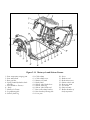
Chapter 2: Chassis and Running Gear
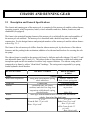
2.1 Description and General Specifications . . . . . . . . . . . . . . . . . . . . . . . . . . . . . . . . . .
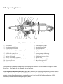
2.2 Operating Controls . . . . . . . . . . . . . . . . . . . . . . . . . . . . . . . . . . . . . . . . . . . . . . . . . .
2.3 Front Fork and Suspension . . . . . . . . . . . . . . . . . . . . . . . . . . . . . . . . . . . . . . . . . . . .
2.4 Rear Suspension . . . . . . . . . . . . . . . . . . . . . . . . . . . . . . . . . . . . . . . . . . . . . . . . . . . .
2.5 Brakes . . . . . . . . . . . . . . . . . . . . . . . . . . . . . . . . . . . . . . . . . . . . . . . . . . . . . . . . . . . .
2.6 Wheels, Tires, Shock Absorbers and Springs . . . . . . . . . . . . . . . . . . . . . . . . . . . . .
2.7 Fenders . . . . . . . . . . . . . . . . . . . . . . . . . . . . . . . . . . . . . . .. . . . . . . . . . . . . . . . . . . . .
2.8 Bench Seats . . . . . . . . . . . . . . . . . . . . . . . . . . . . . . . . . . . . . . . . . . . . . . . . . . . . . . . .
2.9 Windshield and Fairing . . . . . . . . . . . . . . . . . . . . . . . . . . . . . . . . . . . . . . . . . . . . . . .
36
38
44
50
51
54
62
62
62
Chapter 3: Sidecar
3.1 Description and General Specifications . . . . . . . . . . . . . . . . . . . . . . . . . . . . . . . . . .
3.2 Installation and Removal . . . . . . . . . . . . . . . . . . . . . . . . . . . . . . . . . . . . . . . . . . . . . .
3.3 Sidecar Alignment . . . . . . . . . . . . . . . . . . . . . . . . . . . . . . . . . . . . . . . . . . . . . . . . . . .
3.4 Frame/Attachment . . . . . . . . . . . . . . . . . . . . . . .. . .. . . . . . . . . . . . . . . . . . . . . . . . . .
3.5 Suspension . . . . . . . . . . . . . . . . . . . . . . . . . . . . . . . . . . . . . . . . . . . . . . . . . . . . . . . . .
3.6 Sidecar body . . . . . . . . . . . . . . . . . . . . . . . . . . . . . . . . . . . . . . . . . . . . . . . . . . . . . . .
3.7 Handling Differences Between Single & Dual Wheel Drive . . . . . . . . . . . . . . . . . . .
3.8 Driven Sidecar Wheel . . . . . . . . . . . . . . . . . . . . . . . . . . . . . . . . . . . . . . . . . . . . . . . .
3.9 Fender . . . . . . . . . . . . . . . . . . . . . . . . . . . . . . . . . . . . . . . . . . . . . . . . . . . . . . . . . . . .
3.10 Upholstery . . . . . . . . . . . . . . . . . . . . . . . . . . . . . . . . . . . . . . . . . . . . . . . . . . . . . . . .
65
66
67
69
70
71
72
73
77
77
Chapter 4: Engine
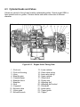
4.1 Description and General Specifications . . . . . . . . . . . . . . . . . . . . . . . . . . . . . . . . . .
4.2 Repair Information and Service Limits . . . . . . . . . . . . . . . . . . . . . . . . . . . . . . . . . . .
4.3 Cylinder Heads and Valves . . . . . . . . . . . . . . . . . . . . . . . . . . . . . . . . . . . . . . . . . . . .
4.4 Cylinders and Pistons . . . . . . . . . . . . . . . . . . . . . . . . . . . . . . . . . . . . . . . . . . . . . . . .
4.5 Camshaft, Timing Gears, Tappets . . . . . . . . . . . . . . . . . . . . . . . . . . . . . . . . . . . . . . .
4.6 Oil Pump and Delivery . . . . . . . . . . . . . . . . . . . . . . . . . . . . . . . . . . . . . . . . . . . . . . . .
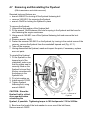
4.7 Removing and Reinstalling the Flywheel . . . . . . . . . . . . . . . . . . . . . . . . . . . . . . . . . .
4.8 Crankshaft and Connecting Rods . . . . . . . . . . . . . . . . . . . . . . . . . . . . . . . . . . . . . . .
4.9 Crankcase and Covers . . . . . . . . . . . . . . . . . . . . . . . . . . . . . . . . . . . . . . . . . . . . . . .
78
83
84
93
99
102
105
106
112
1
Chapter 5: Gearbox
5.1 Description and Specifications . . . . . . . . . . . . . . . . . . . . . . . . . . . . . . . . . . . . . . . . . .
5.2 Gearbox (Solo Motorcycle) . . . . . . . . . . . . . . . . . . . . . . . . . . . . . . . . . . . . . . . . . . . .
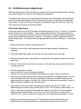
5.3 Shift Mechanism Adjustment . . . . . . . . . . . . . . . . . . . . . . . . . . . . . . . . . . . . . . . . . . .
5.4 Gearbox Removal and Installation . . . . . . . . . . . . . . . . . . . . . . . . . . . . . . . . . . . . . .
5.5 Gearbox Disassembly and Reassembly . . . . . . . . . . . . . . . . . . . . . . . . . . . . . . . . .
5.6 Repairing the Gearbox Assembly Units and Parts . . . . . . . . . . . . . . . . . . . . . . . . .
113
118
121
123
124
127
Chapter 6: Clutch
6.1 Description and Specifications . . . . . . . . . . . . . . . . . . . . . . . . . . . . . . . . . . . . . . . . .
6.2 Clutch Adjustment . . . . . . . . . . . . . . . . . . . . . . . . . . . . . . . . . . . . . . . . . . . . . . . . . . .
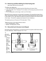
6.3 Removing and Reinstalling the Clutch Release Mechanism . . . . . . . . . . . . . . . . . .
6.4 Clutch Repairs . . . . . . . . . . . . . . . . . . . . . . . . . . . . . . . . . .. . . . . . . . . . . . . . . . . . . .
6.5 Clutch Reassembly . . . . . . . . . . . . . . . . . . . . . . . . . . . . . . . . . . . . . . . . . . . . . . . . . .
133
134
134
135
136
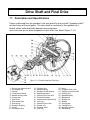
Chapter 7: Driveshaft and Final Drive
7.1 Description and Specifications . . . . . . . . . . . . . . . . . . . . . . . . . . . . . . . . . . . . . . . . . .
7.2 Removal and Installation of Final Drive . . . . . . . . . . . . . . . . . . . . . . . . . . . . . . . . . . .
7.3 Removing and Reinstalling Propellor Shaft . . . . . . . . . . . . . . . . . . . . . . . . . . . . . . . .
7.4 Removing and Reinstalling the Rear Swing Arm . . . . . . . . . . . .. . . . . . . . . . . . . . . .
7.5 Driveshaft and Universal Joint Repair . . . . . . . . . . . . . . . . . . . . . . . . . . . . . . . . . . . .
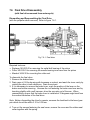
7.6 Final Drive Disassembly . . . . . . . . . . . . . . . . . . . . . . . . . . . . . . . . . . . . . . . . . . . . . .
7.7 Repairing the Final Drive . . . . . . . . . . . . . . . . . . . . . . . . . . . . . . . . . . . . . . . . . . . . . .
7.8 Final Drive with Driven Sidecar Wheel (Sportsman) . . . . . .. . . . . . . . . . . . . . . . . . .
137
138
138
139
139
141
143
145
Chapter 8: Electrical
8.1 Description and Specifications . . . . . . . . . . . . . . . . . . . . . . . . . . . . . . . . . . . . . . . . . .
8.2 Maintenance and Troubleshooting . . . . . . . . . . . . . . . . . . . . . . . . . . . . . . . . . . . . . .
8.3 Battery . . . . . . . . . . . . . . . . . . . . . . . . . . . . . . . . . . . . . . . . . . . . . . . . . . . . . . . . . . . .
8.4 Alternator . . . . . . . . . . . . . . . . . . . . . . . . . . . . . . . . . . . . . . . . . . . . . . . . . . . . . . . . . .
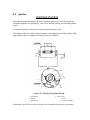
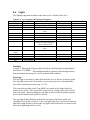
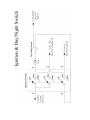
8.5 Ignition . . . . . . . . . . . . . . . . . . . . . . . . . . . . . . . . . . . . . . . . . . . . . . . . . . . . . . . . . . . .
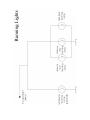
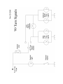
8.6 Lights . . . . . . . . . . . . . . . . . . . . . . . . . . . . . . . . . . . . . . . . . . . . . . . . . . . . . . . . . . . . .
8.7 Horn . . . . . . . . . . . . . . . . . . . . . . . . . . . . . . . . . . . . . . . . . . . . . . . . . . . . . . . . . . . . . .
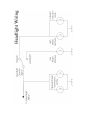
8.8 Turn Signals . . . . . . . . . . . . . . . . . . . . . . . . . . . . . . . . . . . . . . . . . . . . . . . . . . . . . . . .
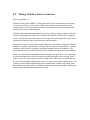
8.9 Wiring, Switches, Fuses, Connectors . . . . . . . . . . . . . . . . . . . . . . . . . . . . . . . . . . . .
147
147
149
153
155
158
159
159
160
Chapter 9: Fuel, Carburetion, Air Intake, Exhaust
9.1 Description and Specifications . . . . . . . . . . . . . . . . . . . . . . . . . . . . . . . . . . . . . . . . . .
9.2 Fuel Tank, Fuel Valve . . . . . . . . . . . . . . . . . . . . . . . . . . . . . . . . . . . . . . . . . . . . . . . .
9.3 Carburetors . . . . . . . . . . . . . . . . . . . . . . . . . . . . . . . . . . . . . . . . . . . . . . . . . . . . . . . .
9.4 Air Filter. . . . . . . . . . . . . . . . . . . . . . . . . . . . . . . . . . . . . . . . . . . . . . . . . . . . . . . . . . . .
9.5 Exhaust pipes & Mufflers . . . . . . . . . . . . . . . . . . . . . . . . . . . . . . . . . . . . . . . . . . . . . .
161
161
162
164
165
Chapter 10: Repair Supplies
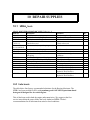
10.1 URAL Seals . . . . . . . . . . . . . . . . . . . . . . . . . . . . . . . . . . . . . . . . . . . . . . . . . . . . . .
10.2 Lubricants . . . . . . . . . . . . . . . . . . . . . . . . . . . . . . . . . . . . . . . . . . . . . . . . . . . . . . . . .
166
166
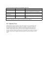
10.3 Substitute Parts . . . . . . . . . . . . . . . . . . . . . . . . . . . . . . . . . . . . . . . . . . . . . . . . . . . .
167
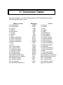
Chapter 11: Conversion Tables
168
Appendix
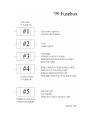
# 1 Wiring Schematics . . . . . . . . . . . . . . . . . . . . . . . . . . . . . . . . . . . . . . . . . . . . . . . . . . .
# 2 Troubleshooting Guides. . . . . . . . . . . . . . . . . . . . . . . . . . . . . . . . . . . . . . . . . . . . . . . .
169
179
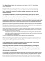
This Repair Manual deals with maintenance and repair of all U.S. Specification
URAL motorcycles.
The Repair Manual provides information on setup, tune-ups, servicing, diagnosing
problems, removing and installing components (otherwise referred to as "assembly
units"), overhauling components, adjusting repaired components, and testing the
repaired motorcycle.
The increasing competition in the motorcycle market requires, more than ever, careful
attending to the customer in order to assure the owner satisfaction with one’s motorcycle and
to maintain customer confidence in the dealer and factory.
It is important to repair the client’s vehicles correctly in a well organized and clean repair shop
equipped with all necessary tools and parts. In such an environment, and having been trained
at the technical training course, a repair technician will prove to be competent and efficient.
Repairs on the engine and transmission especially, should be carried out in dust-free places.
During breaks, disassembled transmissions and openings leading to the inner engine parts or
lubrication holes should be protected from dust by clean rags.
Valves, valve springs, spring retainers, rockers, pushrods, tappets, pistons, connecting rods
and bearings should be put away in suitable boxes. Disassembled parts have to be cleaned
and thoroughly checked for the following:
Sliding and rolling surfaces for wear and freedom from scoring marks, all metal parts,
particularly castings, tempered parts and welded joints as well for cracks and corrosion,
and rubber parts for suitableness.
As a rule, all gaskets and tab washers are to replaced upon reassembling.
When disassembling parts, attention has to be paid to the arrangement of lock-washers on
screws and nuts, spacing washers, gaskets, rubber mounts and so on. If necessary, mark
mating parts in order to guarantee correct assembly.
As the reassembly has to be carried out precisely in the reverse order, it has not been
considered necessary to separately explain the assembly.
Proper service and repair is important for the safe, reliable operation of all mechanical
products. The service procedures recommended and described in this Service Manual are
effective methods for performing service operations. Some of these service operations
require the use of tools specially designed for the purpose. These special tools should be
used when and as recommended.
It is important to note that some warnings against the use of specific service methods, which
could damage the motorcycle or render it unsafe are stated in this Repair Manual. However,
please remember that these warnings are not all inclusive. Since Ural could not possibly
know, evaluate and advise the service trade of all possible ways in which service might be
done or of all the possible hazardous consequences of each way, we have not undertaken
any such broad evaluation. Accordingly, anyone who uses a service procedure or tool which
is not recommended must first thoroughly satisfy himself that neither his nor the operator’s
safety will be jeopardized by the service methods selected.
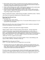
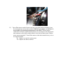
Wear eye protection while using any of these tools: hammers, arbor or hydraulic presses,
gear pullers, spring compressors, and slide hammers. Be especially cautious when using
pulling, pressing or compressing equipment. The forces involved can cause parts to “fly-out”
with considerable force and cause bodily injury.
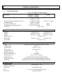
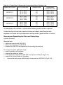
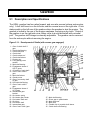
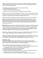
GENERAL INFORMATION
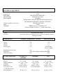
1.1
SPECIFICATIONS
GENERAL
Maximum speed of motorcycle
Reference fuel consumption at 85% of
maximum speed
Dry mass of motorcycle
Maximum load-carrying capacity
Noise level
*Note: -10 Models are Deco Classics
TOURIST / SPORTS
SOLO
UTILITY/ *-10 Mdls
108 km/h / 65 mph
122 km/h / 77 mph
*119km/h / 74 mph
12.5 km/l / 29 mpg
16.7 km/l / 39 mpg
14 km/l / 32.5 mpg
700 lb. / *680 lb.
460 lb.
500 lb/485 lb/*400 lb
330 lb.
below 80db
OVERALL DIMENSIONS OF MOTORCYCLE
Length
Width
Height
Road Clearance
Seat height
Wheel base
ENGINE
Type
Displacement
Cylinder bore
Piston stroke
Compression ratio
Rated horsepower
Rated rotational speed
Rated torque, Nm
Ignition system
Lubrication system
Lubricant
CARBURETOR
Carburetor type
Number of carburetors
Air cleaner
Fuel
PCV Valve
2500 mm / 8 ft
2200 mm / 7 ft
1700 mm / 5 ft 6 in
850 mm / 2 ft 8 in
1100 mm / 3 ft 6 in
1060 mm / 3 ft 8 in
125 mm / 5 in
840 mm / 33 in
810 mm / 32 in
1470 mm / 55 in
4 stroke, overhead valves, opposed twin-cylinder
649 cc
78 mm / 3.07 in
68 mm / 2.68 in
8.5
35
5600 RPM
45 Nm / 398.7 in-pound
Contactless with electronic ignition timing
Dual system of forced lubrication and by splashing
SAE 20W/50 (see Owner’s Manual Maintenance Section)
Keihin Seiki 32 CVK
2
Pleated Paper Filter
91 octane premium unleaded gasoline
Internal Breather
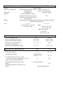
ELECTRICAL EQUIPMENT
Ignition system
Ignition coil
Spark plugs
Ignition timing
Power supplies
Voltage regulator (electronic)
Horn
Headlight
TRANSMISSION
Clutch
Gearbox
GEAR RATIOS
I gear
II gear
III gear
IV gear
Reverse gear
12 V
B204
NGK BP7HS or NDW20FP-1
Automatic spark timer
Alternator
Storage battery (Russian supplied with new motorcycle)
Recommended replacement: Interstate #12N9-4B-1
Internal to Alternator
C205B
URAL part no. UA-TB6014-017
Sylvania Incandescent 6014, 7" round sealed beam
Dry double-disk clutch
4 speed box with reverse gear (no reverse for solo model) and gear
shifting foot pedal
TOURIST / SPORTSMAN / UTILITY
3.6
2.28
1.7
1.3
4.2
SOLO/CRUISER
3.6
2.28
1.7
1.3
N/A on Solo
4.2 on -10 mdls
0.4
0.5
Pair of bevel gears with propeller shaft
4.62
3.89
Speedometer drive ratio
Final drive
Final drive ratio
FLUID CAPACITIES
Gasoline tank
Reserve
Engine crankcase
Gearbox
Final drive
Telescopic Forks
(-10 & solo models)
Shock Absorbers
TOURIST &
-10 Models
19 L / 5 Gal
2L / 0.5 gal
2 L / 2 qt. + 3.6 oz.
0.9L / 1 qt
110 ml / 3.85 oz.
N/A on Tourist
Sportsman
Solo
19L / 5 Gal
2L / 0.5 gal
2.0L / 2.11 qt
0.9L / 1 qt
150 ml / 5.25 oz.
N/A on Sportsman
18.5 L / 4.9 Gal
2L- / 0.5 Gal
2 L / 2 qt. + 3.6 oz.
0.9L / 1 qt
110 ml / 3.85 oz.
135 ml / 4.56 oz.
105 ml / 3.55
105 ml / 3.55 oz
105 ml / 3.55 oz
RUNNING GEAR
Frame
Rear wheel suspension
Front fork
Sidecar
Brakes
Tires
TOURIST / SPORTSMAN
SOLO
Tubular welded
Swing arm with hydraulic spring Sidecar: same as -40
shock absorbers
Solo: Lower spring rate
Leading link
Telescopic spring
Cushioned body (on rubber
cushions) and wheel on long-lever
N/A
suspension with hydraulic spring
shock absorber
Shoe-type with mechanical drive on front, rear and sidecar wheels,
front wheel has dual cams.
4” x 19”
3.5” x 18”
Front & Side: 22 psi cold
Solo:
Rear: 36 psi cold
Front 25 psi cold
Rear: 32 psi cold
-10’s: Front & side:
25 psi cold
Rear: 36 psi cold
CLEARANCES
Valves with engine cold
Between spark plug electrodes
Between brake shoes and drum
Backlash between tooth faces of
bevel gears in final drive
Between rotor and ignition pickup
FREE TRAVEL / ADJUSTMENTS
Hand brake control lever
Clutch control lever
Foot brake drive pedal
Toe-in throughout motorcycle center
distance (exception: Sportsman 0° toe-in)
Angle of motorcycle inclination to
vertical plane (camber angle of rear
wheel)
Headlight installation (with motorcycle
laden)
mm
0.05
0.50 - 0.65
0.3 - 0.70
0.1 - 0.3
in
0.002
0.020 - 0.026
0.012 - 0.028
0.004
0.3 - 0.4
.012 - .016
mm
5-8
5-8
¼ of full stroke of
pedal, 25 - 30
in
0.2 - 0.3
0.2 - 0.3
1.0 - 1.2
10
N/A
1° away from sidecar
N/A
horizontal (high beam)
TORQUE SPECIFICATIONS
Metric (in repair manual)
29 to 33 Nm
22 to 25 kgf-m
3.8 to 4.2 kgf-m
2.1 to 3.0 kgf-m top
3.6 to 5.0 kgf-m bottom
3.0 to 3.4 kgf-m
3.0 to 3-4 kgf-m
1.6 to 1.8 kgf-m
.8 to 1.0 kgf-m
1.4 to 1.8 kgf-m
7 to 9 kgf-m
2.2 to 2.8 kgf-m
1.8 to 2.0 kgf-m
14.0 to 16.8 kgf-m
US Equivalent
22 ft/lb. to 30 ft/lb.
175 ft/lb. to 185 ft/lb.
30 ft/lb. to 40 ft/lb.
14 ft/lb. to 22 ft/lb.
28 ft/lb. to 36 ft/lb.
22 ft/lb. to 26 ft/lb.
22 ft/lb. to 26 ft/lb.
12 ft/lb. to 14 ft/lb.
5 ft/lb. to 8 ft/lb.
10 ft/lb. to 14 ft/lb.
50 ft/lb. to 66 ft/lb.
16 ft/lb. to 20 ft/lb.
14 ft/lb. to 16 ft/lb.
100 ft/lb to 120 ft/lb
Location on Bike
cylinder heads
fly wheel tightening screws
cylinder
shock absorber
shock absorber
bearing nut
final drive to swing arm bolts
oil pump bolt
engine sump
final drive case nuts
nut fastening the pinion bearing
reverse gear brake lever
generator gear nut
steering stem nut
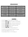
CONVERSIONS
To convert from mm to in, divide by 25.4 (there are 25.4 mm per inch).
To convert from liters to gallons, divide by 3.785 (there are 3.78 liters per gallon).
To convert from liters to quarts, multiply by 1.056 (there are 1.056 quarts per liter).
To convert from liters to pints, multiply by 2.112 (there are 2.112 pints per liter).
To convert from km to miles, multiply by .62 (there is .62 mile per km).
To convert from km/hr to mph, multiply by .62.
To convert from Newton-meter (Nm) to inch-pound, multiply by 8.86.
To convert from cm3 (cc) to pints, divide by 473 (there are 473 cc per pint).
To convert Celsius to Fahrenheit, F° = C° x 1.8 = 32°.
To convert Fahrenheit to Celsius,C ° = (F° - 32° ) divided by 1.8
CAUTION: During the initial 2,500 km of use a fundamental bedding-in of parts for all the
mechanisms of the motorcycle takes place. During this period do not overload the engine or race the
motorcycle in excess of the speeds specified in the section "Running-In of New Motorcycle." Doing
so will void the warranty.
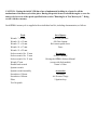
Each URAL motorcycle is supplied with an individual tool kit, including documentation, as follows.
Tools
Wrench 7 x 8 mm
Wrench 10 x 12 mm
Wrench 13 x 14 mm
Wrench 14 x 17 mm
Wrench 19 x 22 mm
Socket wrench 10 x 12 mm
Socket wrench 10 x 13 mm
Socket wrench 19 x 21 mm
Wrench 27 mm
Double head wrench
Spanner wrench
Spanner wrench assembly
Screwdriver 150 mm
Screwdriver 100 mm
Pliers
Tool kit pouch
Set of Spares
Inner tube patch kit
Oil filter element
Kick starter pedal sleeve
Fuses
Documents
Owner’s Manual
Driving the URAL Sidecar Manual
(except with Solo models)
Owner’s Video
Accessories
Air Pump
Air Pressure Gauge
2 Ignition keys
1.2
Maintenance, Lubrication, & Tune-up
Maintenance Intervals
Maintenance intervals recommended are based on operational experience under various climatic and
road conditions. However, these intervals may be extended or reduced following repeated checks of
the lubricant condition and general technical condition of the motorcycle.
In certain sections of this manual you will find references to more frequent maintenance intervals than
the "Light Duty" minimal maintenance intervals referred to in the Maintenance Schedule Summary. The
sidecar motorcycle requires adherence to the "Normal Duty" maintenance schedule.
Maintenance Schedule Summary
The following schedule is broken into two columns to indicate the type of usage and operating
environment to which the machine will be subject. The "Normal Duty" category includes operation in
dusty, hot climates, while pulling loads on hilly terrain for significant periods of time in the
maintenance cycle, operation primarily with the sidecar accessory attached or for owners who want to
take extra care to keep their machines in "tip top" condition.
The "Light Duty" schedule is the minimal maintenance that an owner should perform to keep the
factory warranty in place. It is acceptable when the machine is used primarily in ideal climates with
very little dust or contamination of fuel supply and with sidecar accessory unattached.
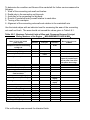
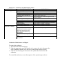
Maintenance Schedule Summary
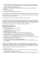
1. Change motor oil, clean or replace oil filter element, clean air filter element and fuel filter,
check bearings play. Check electronic ignition pickup air gap. Adjust throttle, clutch and
brake cables, and check gearshift linkage for adjustment. Check battery fluid.
At 500km then every 2,500km
2. Change gearbox oil, replace oil filter, and rotate tires.
Every 5,000km
3. Lubricate drive axle/hub, replace final drive gear oil.
Check level every 2,500km,
Replace at 500km and every 10,000km
4. Replace spark plugs, torque cylinder head stud nuts, adjust valve lash, re-pack wheel
bearings, and check ignition timing.
Every 10,000km
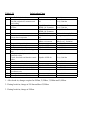
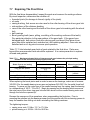
Table 1.2-1
Item
1
2
3
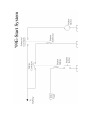
Lubrication Chart
Part To Be Lubricated
Lever pin and interrupter felt
Pins and weight holes, automatic unit
cam bushing
Engine crankcase
Oil filter
Gearbox
Lubricant
Industrial oil or spindle
oil
Schedule
Every 5,000 km
Every 5,000 km
20w/50 Det. oil and
URAL Oil Treatment
20w/50 Det. oil and
URAL Oil Treatment
Spray WD-40
Industrial oil or spindle
oil
Every 2,500 km1
Every 5,000 km
Every 2,500 km2
4
5
6
7
8
9
10
11
12
13
14
15
16
17
18
Air cleaner
Shock absorbers of rear suspension and
sidecar wheel suspension
Final drive
Hinges of sidecar collet joint
Hinge joints of brake system
Brake pedal shaft
Universal joint of propeller shaft (grease
cup)
Lever pins and end pieces of clutch and
hand brake cables
Clutch, front brake and throttles control
cables
Pins and cams of brake shoes
Wheel hub
Front fork dampers (lubrication points)
Carburetor throttle control twist grip
Speedometer drive flexible shaft and
speedometer axle
Steering column bearings
Telescopic forks (-10 and Solo)
Wash and oil every 2,500 km
Change every 10,000 km
Grease
Spindle oil/WD-40
Spindle oil/WD-40
Grease
Top up every 2,500 km3,
change every 10,000 km
Every 10,000 km
Every 5,000 km
Every 2,500 km
Every 10,000 km
Grease
Every 5,000 km
Spindle oil/WD-40
Every 5,000 km
Grease
Grease
Spindle oil/WD-40
Grease
Industrial oil or spindle oil
Every 5,000 km
Every 10,000 km
Change every 10,000 km
Every 5,000 km
Every 10,000 km
Grease
5 wt. -10 wt. Fork Oil
Every 20,000 km
As needed
80/90 wt. Gearlube and
URAL Oil Treatment
1. After break-in, changes required at 500km, 2,500km, 3,500km and 5,000km.
2. During break-in, change at 500 km and then 2,500km.
3. During break-in, change at 500km.
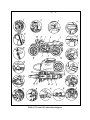
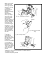
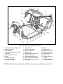
Table 1.2-1 (cont’d) Lubrication diagram
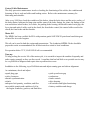
Control Cable Maintenance
The daily preventive maintenance involves checking the functioning of the cables, the condition and
fastening of the tie rods and cables and braking action. Refer to the maintenance summary for
lubricating and schedule.
After every 5,000 km, check the condition of the brakes, clean the brake shoes and the active surface of
the brake drums, lubricate the hinge pins and the cams of the brake linings, the joints, the linkage of the
rear and sidecar wheel brakes, lever axles, the parking brake bearing, the throttle control twist grip, the
lever pins and ends of cables used in the clutch, the front brake control, the control cables used in the
clutch, the front brake and the throttles.
Motor Oil
The URAL has been certified for EPA with premium grade SAE 20W/50 petroleum based detergent
oil rated for air-cooled engines.
This oil can be used in both the engine and transmission. The Authorized URAL Dealer should be
prepared to make recommendations for all lubricants best suited to local conditions.
For operation below 32º F, SAE 10W/40 oil is recommended.
Tune-up
To help prolong the service life of the motorcycle, it is essential to inspect the machine frequently and
make repairs promptly as they are discovered. A machine that has had little or no periodic service may
be very difficult to diagnose and repair when a problem does occur.
In addition to the following, top off all lubricants and adjust running gear and sidecar alignment.
As a minimum, check and adjust:
• spark plug gaps
• valve clearances
• throttle synchronization
• clutch
• adequate fuel quantity, condition, and flow
• acceptable quantity and condition of oil in
the engine crankcase, gearbox, and final drive
• pick up and rotor gap
• carburetors
• brake controls
• drive housing
• all switches and lights functioning
• battery condition and charge
1.3
Normal Operation
This section describes techniques and precautions for operating a URAL motorcycle, including breakin procedures for new or rebuilt engines.
Pre-ride Preliminaries
Before each ride, attend to all the requirements of the everyday maintenance as outlined in this manual.
When filling the motorcycle with fuel and oil, take care to avoid spills that might damage the machine
or create safety or environmental hazards. The fuel tank should not be overfilled. Overfilling can
result in fuel leakage during operation. Always check engine oil level before starting the engine.
CAUTION: When checking or topping off lubricants use caution to prevent dirt and debris
from falling into the fill opening. When using funnels, tubes, pumps, etc., ensure they are not
contaminated with dust or dirt. When draining oil, use care to prevent oil from contacting
wheels, tires, or brakes, and avoid skin contact with used oil.
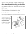
Starting The Engine
WARNING: Before starting the engine, make sure that the gear shift mechanism is in the neutral
position (between I and II gears) to prevent sudden accidental movement which could cause possible
damage to motorcycle and personal injury. For sidecar motorcycles equipped with a reverse gear,
make sure that reverse is not engaged.
If ignition is switched on, the green neutral light on the instrument panel should illuminate when the
transmission is in neutral, however, the neutral light will also be on if the motorcycle is in reverse gear.
Check to be sure that the reverse lever is in the forward position, or manually roll the motorcycle
forward and back to ensure that both transmission and reverse are in neutral before starting.
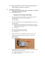
Open the fuel petcock by setting its handle to the down position.
NOTE: For URAL s manufactured earlier than mid-95, the down position is off. This type of valve
has a flatter / wider blade than the later valves. If in doubt, verify fuel flow by removing the fuel line at
the carburetors. (Reserve is up and off is horizontal.)
Getting a URAL engine started is an art that must be mastered. Owners may need to be coached
through the process. The use of throttle and carburetor enrichment is critical for successful starting, as
is a fully-charged battery. Depending on the engine
and ambient temperatures, use the carburetor enricheners and starting procedure as follows.
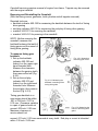
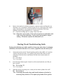
Starting A Warm Engine
When the engine is hot, do not enrich the carburetors. To do so risks flooding the engine. Turn on the
ignition, check the cutoff switch in the run position, select neutral gear, and push down on the kick
lever just far enough to engage it; about 1/4 of its travel. The standard Russian position for starting the
sidecar motorcycle is standing on the passenger peg on the right foot, and stepping down on the
kickstarter with the ball of the left foot. Take up the slack in the throttle until you can feel some slight
resistance from the return springs in the carburetors. However, do not advance the throttle, since this
may flood the engine.
Step down swiftly on the kickstart lever and give it a full stroke to the bottom stop. If the engine starts,
tickle the throttle (rapidly twist part way towards full throttle and then back off) to keep the engine
running, but don't allow it to rev up.
WARNING: Once the engine starts, do not allow it to rev beyond 2,000 rpm while cold, which may
lead to seizure of the piston pin and pistons in the cylinders. Cold oil flows through the oil ducts
more slowly and cannot provide sufficient lubrication.
A correctly adjusted warm engine should run steadily at low speed with the throttle control twist grip
fully closed. Start driving the motorcycle only after having warmed up the engine, with the engine
running steadily at low speed. In cold seasons do not run the engine at high RPM during initial 3 km or
drive at a speed exceeding 30 mph until the engine is fully warmed up.
If the engine doesn't start on the first kick, kick it through aggressively, four or five times. A properly
adjusted warm engine should start within a few kicks. If the engine doesn't start, or coughs, that
indicates it is cold enough to require some enriching of the mixture. However, it may also be flooded.
Flooded Engine
To start an engine that is flooded pull out both enrichers, open the throttle fully, hold it there and kick
the engine through several times. It should fire. As soon as it fires, return the throttle to just above idle
to keep it running. If it still doesn't fire, take the spark plugs out to see if they are very wet with
gasoline. If they are wet, dry them, and clear excess gasoline from the cylinders by kicking the engine
over several times with the plugs out and the throttle closed. Then replace the plugs and repeat the
starting procedure using no enricheners.
Cold Engine, Warm Day
When the engine has been standing for several hours but the ambient temperature is high (60°F or
above), it will probably start without enrichment. If it doesn't fire, use one of the following procedures.
Cool Engine, Cool Day
When the engine is cool or cold and the ambient temperature is between 40-60 F, pull out both
enricheners. As soon as the engine starts, immediately push both enricheners back in. Run the engine at
moderate speed for 30-60 seconds. If it starts to die, tickle the twist grip throttle (rapidly twist part way
towards full throttle and then back off) to keep the engine running. After 1 to 3 minutes, depending on
ambient temperature, the engine should run smoothly.
Cold Weather Starting
If the engine is cold and ambient temperature is below 40 degrees F, first, give the engine 5-10
(depending on how cold it is) priming kicks with the ignition off. This will get some oil circulated to
key internal parts. Pull open the enricheners on both carburetors The engine should then soon fire,
depending on how cold it is. For example, when the ambient temperature is 0 degrees F, it typically
takes about 3 to 5 seconds to start the engine. As soon as the engine starts, push in both enricheners.
Then follow the running procedure described in Starting the Engine (also in section 1.3).
NOTE: It is very important to back off on the enricheners as soon as the engine will sustain itself
without sputtering. The URAL can foul plugs quickly (as soon as one minute) if the engine is run too
rich. If one plug fouls and the other doesn't, the engine will run very unevenly and have greatly
reduced power.
WARNING: Sustained operation on only one cylinder for even just a few minutes could overheat
the cylinder and cause irreversible damage to either the valves or piston. Thus it is critical to
immediately shut the engine down if it appears to be running on only one cylinder.
Operating Precautions
WARNING: Make sure that sidecar windshield is in the full back position and it doesn't interfere
with the right handlebar.
To move the motorcycle from rest, shift to the 1st gear only. Avoid releasing the clutch suddenly,
because the engine is liable to stall or the motorcycle will start with a jerk.
Do not drive the motorcycle at speeds below the recommended speeds with the 2nd, 3rd or 4th gears
engaged. It is not advisable to use the 1st and 2nd gears for a long time, unless so required by road
conditions.
WARNING: When shifting to lower gears with the motorcycle in motion, do not downshift at speeds
higher than those listed in the table. Shifting to lower gears when speed is too high may severely
damage the transmission or cause the rear wheel to lose traction.
Shift to neutral before shutting off the engine. The shifting mechanism can be damaged by attempting
to shift the transmission when the engine is not running. When engine speed decreases, as in climbing
a hill or running at a reduced speed, change from a higher gear to the next lower gear while partially
closing the throttle.
CAUTION: Do not run the engine at extremely high rpm with clutch disengaged or transmission
in neutral. Do not idle the engine unnecessarily for more than a few minutes with the motorcycle
standing still. Remember the URAL engine is an air cooled engine which requires the movement
of air to keep the engine at normal operating temperatures and to avoid overheating the
cylinders.
An engine run long distances at high speed must be given close attention, to avoid overheating and
consequent damage. The engine should be checked regularly and kept well tuned. Valve seating and
good compression is particularly important, especially for a sidecar motorcycle equipped with
windshields, carrying heavy loads, or operating in hot weather.
WARNING: When riding on wet roads or under rainy conditions, braking efficiency is greatly
reduced and caution should be used when applying the brakes, accelerating and turning. This is
especially true immediately after the rain begins and the oil from the road surface combines with the
water.
When descending a long, steep grade, downshift and use engine compression together with intermittent
application of both brakes to slow the motorcycle. Drum-type brakes tend to overheat and fade if used
continuously.
Shutting Down an Overheated Engine
An overheated engine can backfire or detonate when being shut down. The engine jerking at low
speeds is hard on both the engine and the transmission. To avoid damage when shutting down an
overheated engine, reduce the engine speed to the minimum and completely close the choke without
switching off the ignition. This will make the engine stall without any knocks or backfire. After the
engine stops, switch off the ignition.
Running In a New Motorcycle
URAL motorcycles require a running-in period to allow new parts such as bearings to seat. The
running-in period also applies to new or overhauled components. Since the URAL engine is an old
fashioned design it is critical to observe this running-in procedure. Failure to follow the running-in
procedure will void the Ural warranty.
During the running-in period, a new motorcycle requires the most careful attention. In the course of
this period, do not overload the machine, avoid traveling on freeways and climbing steep upgrades. Do
not race the engine or allow it to overheat at any time.
Pay special attention to lubrication of the engine. It is recommended that after the initial 500 km, the
break-in oil be drained, the crankcase flushed, and refilled with fresh oil to the correct level.
Transmission and final drive lubricants can be changed per the normal maintenance schedule summary.
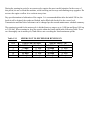
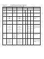
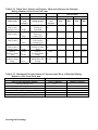
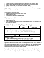
The running-in period for the motorcycle is divided into two stages, up to 1,000 km and from 1,000 up
to 2,500 km. When running-in, keep the speeds within the limits stated in the following Table. Even
on a thoroughly run-in motorcycle, Ural advises not exceeding the listed maximum speeds:
Table 1.3-1
Gear
I
II
III
IV
SPEEDS NOT TO EXCEED FOR RUNNING-IN
Tourist (-40 ) & Patrol
After Run-In
0 - 2,500 km
12 mph
9 mph
27 mph
21 mph
39 mph
30 mph
65 mph
42 mph
Solo & Cruiser ( -10 )
After Run-In
0 - 2,500 km
15 mph
10 mph
31 mph
22 mph
74 mph
40 mph
70 mph
50 mph
1.4 Troubleshooting
Troubleshooting
Although some parts may fail suddenly, most parts degrade gradually and troubles that develop over a
period of time tend to go unnoticed by the owner. The engine may gradually lose power as the
cylinders lose compression. Oil and fuel consumption gradually increase. Noises gradually get louder.
Seals may start to weep oil, or hoses begin to disintegrate. Metal parts form corrosion and rust. All of
this degradation affects the operation and serviceability of the motorcycle.
When a machine is brought in for repairs, the relative condition of the motorcycle should be
determined by inspection and by operational testing and measurement if needed. Allowing a machine
with obvious defects to leave the shop exposes the shop to potential liability. The motorcycle owner
may assume the shop has inspected the machine for defects as well as repairing specific problems.
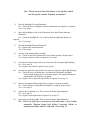
Inspection
Look over the motorcycle carefully to see that all the equipment is complete, especially frame
fasteners, wiring, controls, suspension and brakes. Look for lubricant leakage from seals, including
engine, transmission, final drive, wheel bearings and shock absorbers. The following outline may
serve as a guide.
A. Frame
• no significant dents, cracks or corrosion
• condition of the fender
• frame joints for correct fasteners and proper tightening
B. Fuel tank
• no leaks from welded seams and joints
• proper function of the fuel valve
• hoses intact and in acceptable condition
• no major dents or corrosion of fuel tank
C. Electrical equipment
• operation of the ignition switch, turn indicators, stop light switch, neutral light, alternator
light, high beam indicator, headlight, and horn
• condition of all wiring and plug-and-socket connections
D. Controls
• handlebar twist grip and levers
• throttle control twist grip for easy rotation
• condition of cable armor and internal cables, particularly the end fittings
E. Wheels
• acceptable wear of the brake drum inner surface
• tire wear and condition
• axial play and radial runout of the wheel rim and tire
• no cracks or dents in the wheel rim
• running condition of the wheel hub bearings
• the wheel spokes for uniform tension
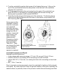
NOTE: Wheels are best inspected by alternatively jacking each wheel off the floor and rotating the
wheel while observing runout of the rim and tire. Check wheel bearings by rotating the wheels and
attempting to rock them laterally on the bearings. The wheels should rotate freely without noticeable
play, seizing, clicks or growling, and there should be no play in the bearings. A quick test of spoke
tension is to tap each spoke with a screwdriver as the wheel is rotated. The pinging sound should be
relatively uniform from spoke to spoke. The tolerated axial or radial runout of the rim is 0.060 inch /
1.5 mm. The tolerated runout of the tire (radial or axial) is 0.120 inch / 3 mm.
F. Front fork
• no play in the steering head bearings
• no play of the leading link in the fork legs
• springs not broken or seized
• shock absorbers not leaking fluid
• acceptable condition of casings and guards
NOTE: The fork should rotate freely in the steering column without any noticeable play, clicks or
notching. The tolerated play of the bottom tips of the fork legs should be within 0.020 inch / 0.51 mm,
with the front portion of the motorcycle left in suspension.
G. Suspension
• smooth operation when bounced
• no leaks of fluid from the shock absorbers
• good condition of the silent blocks
• no play or noise in the joints
NOTE: The suspension arms and shock/springs should all function smoothly, without jamming or
binding.
H. Clutch
Check the clutch mechanism both at rest and with the engine running. With the engine not running,
squeeze the clutch and depress the kickstarter; the engine should not turn over.
• separation of disks when the clutch is squeezed
• no abnormal noises when the clutch is squeezed
• smooth engagement of the clutch when released
• no slipping of the clutch under acceleration
I. Kick starter
• proper engagement of the kickstarter pawl
• starter turns engine without pawl slipping
• kickstarter lever quickly returns to top when released
J. Driveshaft (Propeller shaft) and final drive
(∗(Sportsman sidecar Drive Shaft)
• no excessive play or noise in the flexible coupling joints, universal joint or final
drive gears
• runout of the driveshaft within limits
• acceptable condition of the flexible coupling
• proper tightening of the fastening joints
∗ Safety bolts and safety wires intact
∗ Tightness of differential cover nuts
∗ Straightness of drive shaft
NOTE: The tolerated play in the final drive gearing should not exceed 0.012 inch / 0.3 mm. Driveshaft
(propeller shaft) runout is tolerated within 0.040 inch /1 mm.
K. Exhaust system
• tightness of joints
• no major dents or damage
• no rust holes in mufflers
L. Sidecar
• no abnormal noises in body-to-frame joints
• rubber cushions supporting body intact
• no cracks, major dents, or rust-through in sidecar frame, swing arm, fender, or
sidecar body
• sidecar-to-motorcycle connections tight.
• sidecar wheel bearings in acceptable condition and adjustment
• sidecar brake functional.
When inspecting the motorcycle, observe the condition of the paint and anticorrosive coatings of the
parts. In particular, watch for corrosion under the battery area that could indicate leaking battery acid.
Corroded areas should be cleaned, neutralized, primed, and painted to retard further damage.
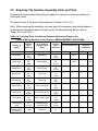
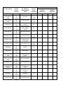
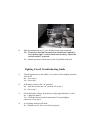
Operational Testing and Measurement
A mechanic experienced with the URAL should be able to quickly determine the condition of an
engine by feeling for hot spots, listening for abnormal noises and
knocking of a running engine using a stethoscope and for condition of running gear by observing
coasting ("free-wheeling") distances. Abnormal noises can be good indicators of potential failures.
Table 1.4-1 lists principal noises and knocks as they relate to probable mechanical problems. Table
1.4-2 is a troubleshooting chart to help diagnose problems with specific tests.
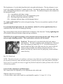
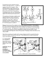
The compression in the engine cylinders can be determined approximately by feeling resistance to
cranking as the start lever is pushed down and more specifically by measurement with a compression
gage. If compression is weak, adjust valve clearances, then measure the compression both "dry" and
"wet" with oil, kicking the engine over the same number of strokes each test with the opposite spark
plug removed.
Dry compression should be at least 100 psi / 700 kPa with no greater than 20 psi / 140 kPa difference
between cylinders. If the compression increases when the cylinder is lubricated with additional oil, that
indicates worn rings. Low compression both "dry" and "wet" indicates leaking valves.
A test ride can quickly help determine the condition of the motorcycle, the operation of clutch,
gearbox, final drive, brakes, and suspension. Prepare to ride, start the engine, release the clutch and
shift into 1st gear the motorcycle should not lurch forward. As the clutch lever is smoothly released.
The motorcycle should begin to move ahead smoothly, without lurching. With the clutch fully
released, quickly roll on the throttle. The motorcycle should immediately pick up speed without the
clutch slipping. The gearbox should shift smoothly without jumping out of any gear. When stopping,
the brakes should apply smoothly with no abnormal noises or jerking. With the transmission in neutral,
shifting to reverse should not take excessive effort and the machine should back up without jerking.
Lubricated bearings should not exhibit significantly greater heating than the rest of the housing.
Localized overheating (hot spots) adjacent to bearing locations indicate probable bearing failure. It is
normal for large gears such as those in the final drive to warm up the housing during operation, but not
get hot to the touch.
Minor oil weeping from joints and seals is considered normal. However, oil dripping or dribbling from
a housing in sufficient quantity to form a several inch diameter puddle under the machine overnight is
considered “significant.”
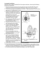
If there is a question whether low performance is caused by running gear or low engine power output, a
coast-down test can help isolate the problem. To measure the coast-down distance, ride the fully laden
motorcycle on a straight, level, paved road section (a smooth asphalt or concrete highway), preferably
in dry and calm weather. At a steady speed of 30 mph / 50 kmph, squeeze the clutch and let the
motorcycle coast to a complete stop. For a URAL in good repair the coasting distance should be at
least 500 feet / 150 meters.
Engine performance can also be measured by a brief maximum speed test on a section of straight, level
pavement. A URAL , equipped with a sidecar, in good condition should easily maintain over 55 mph /
90 kmph.
As a comparison, if coasting distance is shorter than normal, that indicates problems such as dragging
brakes, dragging clutch, worn wheel bearings, final drive bearing failure or sidecar out of alignment. If
the coasting distance is normal, but the engine won't exceed 55 mph, the engine needs at least a tune-up
and maybe repair.
Normal fuel consumption of a URAL on level pavement at 55 mph should be approximately 2 gallons
/ 7.8 L per 100 km for the sidecar outfit, and 1.5 gallons / 6 L per 100 km for a solo machine. Fuel
mileage decreases as engine performance deteriorates.
Normal oil consumption should not exceed 1 pint / 250cc per 200 km. Rising oil consumption
indicates worn rings, worn valve guides or leaking engine seals. Owners who record fuel mileage and
oil consumption may be able to provide such data to the shop.
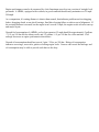
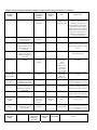
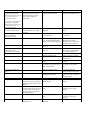
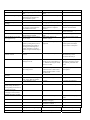
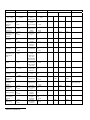
Table 1.4-1 Determining the technical condition of engine by discerning principal noises and knocks
Zone where
knocking is
audible
Nature of knocks
Cylinder area
Clear sharp metallic clink
Ditto
Knocking is less clear and
becomes louder once
engine heats up
Brittle metallic clink
which increases with speed
variation and becomes less
audible when engine is
warmed up.
Similar knocks are audible
when piston pin gets
seized in connecting rod
small end.
Dull knocks of medium
volume
Central portion of
engine crankcase
Point (joint of
parts) where
knocking is
possible
Piston pin to
connecting rod
small end
Thermal
condition of
engine
Engine running
duty
Conclusion about fitness for
further service
Warm
Under load with
sudden transfer
to higher speed
Piston pin to
piston boss
Ditto
Ditto
Discontinue motorcycle
operation. Should knocks
disappear if the ignition is
retarded, adjust ignition timing.
If this does not help, remove
carbon deposit from combustion
chamber and, if need be, replace
piston pin, selecting one to
match the color marking of
connecting rod small end.
Ditto
Piston to
cylinder
Cold
Idle speed
Discontinue operation. Replace
piston and piston pin.
Connecting rod
big end to
crankpin
Random
At idle speed
and especially
when
motorcycle
“drags” in travel
with throttle
valve lowered
only partially
Under load and
once throttle
valves are
suddenly open
Idle running
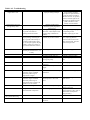
Engine crankcase
at points of
bearing location
Dull low-tone knocks
Main bearings to
crankshaft
Warm
In the area of
gears location
Frequent (clattering)
metallic rolling rattling
(inconstant as to its tone)
Frequent ringing knocks
which increase with
speeding up irrespective of
engine load
Clear metallic clink
Timing gear
Ditto
Valves to valve
seats
Warmed
Idle running and
free wheeling
Clutch discs
Random
Clutch engaged
Point (joint of
parts) where
knocking is
possible
Flywheel to
crankshaft
Thermal
condition of
engine
Engine running
duty
Cylinder heads
Clutch cavity
Zone where
knocking is
audible
Nature of knocks
Rear end of
engine
Dull loud knocking which
disappears once clutch is
fully engaged
Zone where
knocking is
audible
Nature of knocks
Continue operation, if clink
disappears after warming-up of
engine. When repairing, replace
piston.
Point (joint of
parts) where
knocking is
possible
Thermal
condition of
engine
Idle running,
clutch released
Engine
running duty
Discontinue operation. Repair
the engine.
Discontinue operation. Repair
the engine.
Operation is possible. When
repairing engine, replace faulty
gears.
Motorcycle operation is
possible. Readjust clearance.
Grind-in valves, when repairing.
Operation can be continued.
Inspect clutch when repairing
engine/
Conclusion about fitness for
further service
Discontinue motorcycle operation.
Remove clutch, flywheel, check key
joint, remount flywheel and fasten
reliably
Conclusion about fitness for further
service
Front top portion
of engine
Front end of
engine
Frequent rolling
metallic ratting
squeal
Frequent metallic
clink
Generator gear to
camshaft gear
Breather to front
cover
Variable
Warmed
Idle running
Having adjusted clearance between gears
(by turning generator frame), continue to
run the motorcycle normally
Operation can be continued. Inspect
breather, having removed timing cover at
first chance.
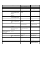
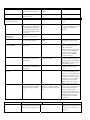
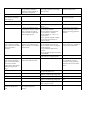
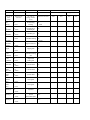
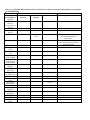
Table 1.4-2. Troubleshooting
Trouble
Engine fails to start.
Symptoms and diagnosing
Engine fails to start with
storage battery intact.
Remedy
Proper starting procedure:
Open petcock. Open enrichener
(pull out) Switch on ignition.
Put kill switch in “on” position
(down). Stand on right foot on
passenger foot pedal, kick start
pedal with left foot. Once
started, close enricheners.
1. Despite gasoline feed to
carburetors, spark plug fails to
ignite the fuel.
A) No gap between plug
electrodes, carbon deposit or dirt
in spark plugs, breakdown of
insulator.
B) No gap between the distributor
contacts, oily or burnt contract.
A) Change faulty spark plugs,
or, depending on their
condition, adjust gap or clean.
C) Faulty ignition coil.
C) Change faulty ignition coil.
D) Break in low-voltage wiring.
E) Ignition module defective.
F) No gap between rotor and
moving coil pickup.
D) Recover wiring.
E) Replace Ignition module.
F) Adjust gap equal to 0.2 - 0.3
mm.
G) Contaminated contacts of plug
connection.
2) Weak or no compression in
engine:
G) Clean plug connection.
A) When depressing the
kickstarter, engine crankshaft
turns freely with no sign of
compression in engine.
B) When depressing the
kickstarter, engine crankshaft
turns freely with no sign of
compression stroke evident in all
cylinders or in one of them.
C) Breather smoking.
A) No clearances in valve timing
mechanism.
A) Adjust clearances properly.
B) Poor seating of valves due to
carbon deposit or valve head
burnt.
B) Repair engine, grind in or
repair valves.
C) Burnt or broken piston rings.
3. Engine crankshaft fails to turn
when kickstarter is depressed.
3. Clutch slipping.
C) Repair engine. Clean or
change piston rings.
3. Adjust clutch controls. If
clutch continues to slip, repair it
(disassemble and inspection
being necessary).
1. Backfire in carburetor.
1. Lean mixture:
A) Undo spark plug connect body
to “ground” and check for
sparking between electrodes.
B) Remove wire lug and check for
proper sparking, connecting the
lug to “ground” with the help of
screwdriver and leaving a slight
gap. If the spark appears, the plug
is faulty. If there is no spark, no
gap between distributor contracts.
C) If there is no spark when
checking as described above, coil
is faulty.
Engine missing/uneven
one cylinder functioning.
Cause
Improper starting technique.
A) Erratic feed of gasoline to
carburetor.
B) Take off crankcase outer
cover, adjust gap between
contacts within 0.4 to 0.6 mm.
Wipe and if need be, clean the
contacts using fine file.
Trouble
Symptoms and diagnosing
3. Pilot lamp is blinking.
A) Engine smokes badly, backfire
in silencer, gasoline leaks from
carburetor.
B) Engine smokes badly, backfire
in silencer, gasoline leaks from
carburetor.
C) Engine smokes badly, backfire
in silencer, gasoline leaks from
carburetor.
8. Synchronized operation of
cylinders disturbed.
9. Lack of compression, engine
smoking, oil fouling the spark
plugs.
Engine Knocking
Engine fails to develop full
power, with throttle
completely open, motorcycle
fails to speed up.
Cause
B) Carburetor jets or unbalanced
channel of float chamber clogged.
2. Faulty spark plugs.
3. Poor contact of battery
terminals.
4. Mixture too rich due to
flooding of float chamber:
A) Float needle valve either dirty
or leaky.
3. Restore proper contact of
battery terminals.
A) Clean the needle valve
B) Float is leaky.
B) Repair or replace faulty
float.
C) Carburetor jet loose.
C) Set jet in place.
8. Carburetor misadjusted.
8. Readjust throttle cables.
9. Piston rings sticking or
damaged.
9. Repair engine, clean or
replace piston.
10. Lack of compression.
10. Valves not seating properly
due to carbon deposit.
1. Knocks disappear, once ignition
is delayed.
2. An expert mechanic determines
the cause by listening to the
running engine.
1. Power increases once ignition is
advanced.
1. Advanced (early) ignition.
10. Repair the engine,
decarbonize and grind-in
valves.
1. Retime engine.
2. Piston pins, pistons, cylinders,
crankpins, main bearings are
worn.
1. Late ignition.
2. Repair the engine.
2. Lack of compression.
2. Valves not seating properly due
to carbon deposit.
3. Piston rings sticking or
damaged.
2. Repair the engine. Remove
carbon and grind in valves.
3. Repair the engine. Clean or
change piston rings.
4. Cylinders and pistons worn
badly.
4. Repair engine. Recondition
or replace cylinders and pistons
in repair shop.
5. Change springs.
3. Lack of compression, engine
smoking, spark plugs fouled with
oil.
4. Verify in repair shop.
5. Valve springs broken.
Engine overheats.
Remedy
1. Engine fails to hold idle speed
1. Mixture too rich.
1. Retime engine.
1. Clean float chamber of dirt,
repair and adjust fuel system.
Trouble
Symptoms and diagnosing
A) Check whether gasoline flows
out of float chamber (overflooding of chamber).
Cause
A) Carburetor flooded due to poor
fit of float valve.
B) Clogged air cleaner.
High oil consumption.
A) Air leakage at carburetor-tocylinder head joints.
B) Backfire in carburetor.
3. Late timing:
3. Power increases, once ignition
is advanced.
1. Smoke emits from breather,
engine smokes, spark plugs wet
with oil.
2. Same as in p. 1.
1. Piston rings burnt or damaged.
2. Cylinder face or piston worn.
3. Breather seat in gearbox cover
worn.
4. Holes for draining oil from
cylinder heads clogged.
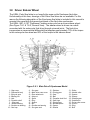
Oil leaks under generator,
under oil pump drive gear
plug, at engine-to-gearbox
joint and under timing box
cover.
Squealing sound in breather.
Breather jammed and its driving
pin sheared.
Clutch slips.
1. Clutch fails to engage fully due
to misadjusted controls.
Breather jammed in cover seat.
3. Oil dripping from breather duct.
2. Repair the engine. Rebore
cylinders or replace them
(change simultaneously the
piston and rings).
3. Repair the engine.
4. Repair the engine.
Breather fouled with aluminum
deposit and scoring of locating
surface in cover seat.
1. Check whether clutch lever play
is sufficient.
Repair the engine.
2. Check when dismantling or
inspecting.
Clutch fails to release fully
(drags).
Misadjusted clutch gear (lever
excessive play).
Check play of clutch lever located
on handlebar.
When kickstarter is
depressed, its pedal moves
down, but engine crankshaft
fails to turn.
1. Pawl, pawl pin or teeth or
kickstarter ratchet are either worn
or damaged. Clutch slips.
1. Having engaged gear, depress
kickstarter. If motorcycle remains
still - it is kickstarter that is faulty.
If kickstarter is operated, but
crankshaft fails to turn, then clutch
is slipping.
Kickstarter pedal fails to
return to top position or
returns slowly.
1. Repair the engine. Change
piston rings.
4. Heavy carbon on spark plug
electrodes, spark plugs oily and
engine smokes.
With engine running, gases are
blocked up in crankcase, heavy oil
leaks through joints.
2. Driven disks oily.
2. Pawl spring is damaged or
weak.
Kickstarter return spring weak or
broken or springloaded pin
sheared.
Remedy
A) Check condition of float
valve and fuel level in float
chamber.
B) Take off air cleaner and
wash it.
B) Tighten nuts fastening the
carburetor to cylinder head.
Should air leakage continue,
change gasket.
3. Retime engine.
Check and make sure that
kickstarter pedal returns
unobstructed to top position.
Repair the engine.
1. Readjust controls by turning
the adjusting screw so as to
provide clutch lever tip play
within 5 to 8 mm.
2. Dismantle the clutch. Wash
disks in gasoline, eliminate
cause of oil clogging.
Readjust clutch gear by turning
the adjusting screw out, so as to
provide full release of clutch
and play of clutch lever within 5
to 8 mm.
1. Repair the gearbox. Change
pawl or reverse it position.
Change pawl pin. Change gear.
Check proper adjustment of
clutch controls. If need be,
readjust it.
2. Repair the gearbox. Change
pawl spring.
Repair the gearbox. Change
spring or pin.
Trouble
1st gear fails to be engaged by
applying gear change foot
pedal, but engages by means of
reverse gear lever set on
quadrant shaft splines.
Symptoms and diagnosing
With gear change foot pedal
depressed to the limit, pedal on
quadrant shaft does not reach
position which engages the
required gear.
Cause
Upper screw of gear change foot
pedal crank is misadjusted.
Remedy
Readjust crank upper screw by
turning out top adjusting screw.
Gear shifting is faultless, but foot
pedal fails to return after being
depressed.
Return spring either weak or
damaged.
Repair gearbox. Change return
spring.
1. Gear change foot mechanism
out of adjustment.
1. Readjust gear change foot
mechanism.
2. Gear shifting deranged due to
wear of quadrant indexing flutes
or due to bent gearshift quadrant.
2. Repair gearbox. Recover
indexing flutes or change
quadrant together with its shaft,
straighten out bent quadrant.
3. Repair the gearbox.
4th gear fails to be engaged by
applying gear change foot
pedal, but engages by means of
reverse gear lever, set on
quadrant shaft splines.
Gear change foot pedal fails
to return to initial position.
Gear disengages
spontaneously with
motorcycle running.
3. Teeth of gear shift sleeves
worn out.
Gear tooth faces of reverse gear
worn out.
Reverse gear disengages
spontaneously with
motorcycle reverse running.
Shifting of gears is difficult.
Seizing of gear shifting forks on
shaft or in quadrant slots.
1. Gear teeth worn out.
Noise in gearbox.
2. Clutch or main shaft bearings
worn.
Backlash between teeth of gears
too small or too great (0.1 to 0.3
mm being tolerated).
Gear noise in final drive.
Overheating of final drive
casing.
1. Wear or damage of parts.
2. Play of brake pedal
misadjusted. (Too tight)
Rattling in front fork.
Oil leaks out of front fork.
RUNNING GEAR
1. Play of steering column in
1. Brake the front wheel and by
thrust bearings.
pushing motorcycle to and fro by
handlebar determine play in thrust
bearings.
2. Set motorcycle up on rear stand, 2. Fork leg tube bushings badly
raise front wheel. If excessive play worn.
is evident when moving legs up
and down, this is a sign of front
fork being damaged.
3. Fork leg tips or springs turned
out.
1. Oil stains on fork leg tips. Check
condition of seal.
1. Front fork leg seals worn or
damaged.
Repair gearbox. Turn over the
gear of reverse gear on bracket
pin or replace starting gear.
Repair the gearbox. Inspect and
replace worn parts, if need be.
1. Repair the gearbox. Change
worn out gears.
2. Ditto. Change worn out
bearings.
Repair the final drive. If need
be, change it or its separate
parts.
1. Repair the final drive.
Change the drive or worn parts.
2. Adjust play correctly. Leave
approx. 1/16 - 1/8” free play at
rear adjusting nut.
1. Eliminate play by tightening
bearings.
2. Repair the fork, check
condition of parts, change
bushings.
3. Undo binding nuts and check.
Tighten tips or springs, if
necessary.
1. Change seals.
Trouble
Shock absorber squeaking
Stiffness of suspension
(bumpy)
Symptoms and diagnosing
2. Check tightening of nuts or
seals.
1. Cocking of upper barrel.
Dismantle shock absorber and
check condition of parts.
Ditto
Check condition of spring.
Cause
2. Fork leg tip seals or their nuts
loose.
Rod unscrewed out of end piece.
Remedy
2. Screw in nuts or seals.
2. Carrier spring broken.
1. Sagging of carrier spring.
2. Replace shock absorber.
1. Replace shock absorber.
2. Dismantle shock absorber, check
for clogging of gauged ducts in
piston and in lower valve.
2. Too much effort required for
shock absorber to expand or
contract.
1. Steering damper bolt too tight.
2. Wash parts and prime shock
absorber with fresh fluid.
Fork rotation is difficult
Steering damper loose (fails
to be tightened up)
Wheel spokes broken
Play of wheel on axle and
wobble of wheel .
Fluid leaks from shock
absorber.
1. Loosen bolt by turning it
counter-clock-wise.
2. Loosen bearings.
2. Test fork rotation by changing
the tightening of bearings.
Steering damper friction washers
oily or soiled.
2. Steering column bearings too
tight.
Disassemble damper and
examine washers.
Examine and check tension of
spokes by setting motorcycle on
stand and turning the wheel, by
pressing the wrench lightly to
spokes, determine by sound if
spokes are tightened uniformly or
not.
1. Gland nut loose and out-ofposition.
Spokes loose or irregularly
tightened.
Repair the wheels. Change
broken spokes and readjust
proper tension of all spokes.
1. Check by visual inspection.
1. Drive the gland nut home,
then slacken by 1/8 of a
revolution and safety it.
2. Bushings or wheel roller
bearings worn out.
2. Make sure that the cause of
trouble is not as described in p.p.
1. Without removing the wheel,
check for wobble.
2. Repair the wheel. Adjust
tightening of bearings. If parts
are replaced, pack them with
grease.
3. Wheel spoke tension disturbed
due to long service.
3. With motorcycle set on stand,
rotate the wheel. Check runout
which should be within 1.5 mm
on wheel rim.
1. Oil leaks from under nut.
3. Readjust proper tension of all
wheel spokes.
2. Fluid leaks along rod.
2. Replace shock absorber.
3. Ditto.
3. Replace shock absorber.
1. Lack of fluid.
1. Add fluid if necessary.
1. Lack of fluid.
1. Add fluid if necessary.
2. Low fluid viscosity.
2. Prime with fluid of proper
grade.
3. Replace the shock absorber.
1. Fluid container nut loose.
2. Shock absorber rod damaged or
worn, scores, dents are evident.
3. Seal damaged or worn.
Shock absorber piston rod
travels freely (no effort) in
the beginning of extension or
compression stroke.
Rear wheel suspension
swinging in excess, knocks
audible when fully extended.
Trouble
1. Screw rod home.
Symptoms and diagnosing
6. Piston broken or deep scores
3. Rebound valve leaky due to
damage or clogging.
4. Rebound valve spring
resilience is reduced.
5. Piston relief valve leaky.
Cause
6. Fluid leaks along rod.
Clean friction washers, check
faces.
1. Tighten fluid container nut.
4. Replace the shock absorber.
5. Replace shock absorber.
Remedy
Shock absorber is knocking.
are evident.
1. Deteriorated rubber bushings
or end fastening silent blocks.
2. Bolts fastening the shock
absorber are loose.
Rear wheel or sidecar wheel
fails to be braked.
Front wheel fails to be
braked.
Brakes overheat.
Trouble
1. Change worn parts.
2. Check fastening bolts.
2. Tighten up bolts.
CONTROLS
1. Adjusting screw too tight.
Carburetor throttle control
grip is difficult to twist.
Once hand is removed from
twistgrip, it turns
spontaneously.
1. Check fastening and conditions
of parts.
1. Loosen and lock adjusting
screw.
2. Lubricate it and see if this
will help. Pull out cable armours
from twistgrip housing and by
twisting the grip and lowering
cable armour determine cause of
slide seizing.
1. Trouble is remedied when
adjusting screw is tightened .
Slide is seized.
2. Lubricate the slide. If
twisting is still difficult, remove
twistgrip, examine it and
lubricate.
Adjusting screw loose.
1. Readjust and lock screw.
2. Tightening of adjusting screw
does not remedy trouble.
Spring that brakes twistgrip is
broken.
2. Repair the twistgrip. Remove
twistgrip and replace spring.
1. Readjust and try out rear
brake action.
Rear brake pedal play misadjusted.
2. After readjustment, as
instructed in p. 1, brake shoes
are slipping.
Brake shoe linings of rear wheel
brake oily or soiled.
3. After readjustment, as
instructed in p. 1m brake shoes
are slipping.
1. Same as for rear wheel.
Brake shoe linings worn.
1. Set up motorcycle on the
stand, check rotation of wheels
without depressing pedal and
lever.
No play in foot brake pedal or front
brake lever, resulting in brake
shoes being constantly pressed to
drum.
1. Reduce play of brake pedal
by turning wing nut on brake
link clockwise and
simultaneously checking wheel
rotation. Leave a slight play of
pedal (1/16 1/8 in) for heat
expansion. After adjustment,
check brake action.
2. Remove wheel, wash brake
shoes in gasoline and wipe dry.
If oiling persists, check quantity
and quality of oil in final drive
and condition of seal.
3. Using adjusting bolts,
readjust clearance of brake
shoes.
1. Reduce play of brake lever
by turning the adjusting screw
in brake cover, simultaneously
check rotation of wheel. Leave
a slight play for heat expansion.
If there is no reserve of thread
on adjusting screw, remove
brake lever and turn it to new
angle on brake cam splines.
1. Set motorcycle on stand.
Turn wing nut of brake pull rod
counter clock-wise until rear
wheel revolves freely. By
turning in adjusting screw on
brake drum cover of front wheel
obtain free rotation of wheel.
After adjusting, check brake
performance.
Symptoms and diagnosing
2. Cam is stuck in position which
corresponds to braking action and
fails to return into initial position.
1. Same as for rear wheel.
Cause
2. Brake cam pin seized.
Remedy
2. Lubricate cam. If trouble
persists, take wheel off, remove
brake cam, wash or reface it, if
necessary.
With ignition lock key in
“ON” position, pilot lamp
fails to light up.
3. Brake cam seized due to large
3. Cam is stuck in position
turn angle, caused by worn linings
corresponding to maximum
of brake shoes.
separation of shoes and fails to
return into initial position.
ELECTRICAL EQUIPMENT
1. Ground switch “Off.”
3. Switch is not grounded
With ignition lock key in
“ON” position, pilot lamp
glows. When horn button is
pressed, horn sounds.
Engine fails to start running.
Weak sparking in spark
plugs.
With parking light “On”
sidecar side lamps fail to
glow.
3. Ensure that the ignition switch
is properly grounded.
2. Check condition of bulb.
2. Lamp is blown.
2. Change faulty bulb.
3. Check if safety fuse is intact.
3. Safety fuse of lighting system is
blown.
4. No contact:
A) on battery terminals
B) on terminal of ground switch
C) on alternator + terminal
D) on terminals “2” and “3” of
master switch.
E) on “ground” terminal of engine.
F) on safety fuse terminals of
ignition system.
1. No contact:
A) on terminal of horn wire lug
B) on terminal of wires in plug and
socket connector
C) on terminal in light turn key
contact
D) on “ground” through switch body
and handlebar.
2. Break in wires of some circuit
link from horn to lighting switch.
1. No contact.
3. Change faulty fuse.
A) no contact on terminals of red
wires from ignition coil.
B) no contact on wire terminal of
ignition coil from high-voltage end.
C)no contact on breaker terminal.
D) no contact on wire terminals of
ignition coil from high-voltage end.
E)no contact on plug tip screw with
high-voltage wire core.
1. Poor contact in coupling block.
ditto
4. Check, if contacts are clean
and tightened. Check, if wiring is
intact, especially wire lugs at
contact terminals of safety fuse
block and ignition lock.
With ignition lock key in
“ON” position, pilot lamp
glows, but there is no sound
when horn button is
depressed.
3. Using adjusting bolts readjust
clearance of brake shoes.
Check that contacts are clean and
tightened. Check that wiring is
intact, especially, wire terminals
of light switch.
1. Check that wiring is in good
order in these links of circuit.
1. If wires are connected outside
the coupling, lamps start
glowing.
4. If necessary, clean contact
surfaces of wire lugs, restore
condition of wiring, tighten the
terminals.
If necessary, clean contact
surfaces of wire lug, recondition
wiring, tighten up terminals.
2. Check and repair open circuit.
1. Clean contact surfaces of wire
lugs, recondition wire lugs,
recondition wiring, tighten up
terminals with screws for better
contact.
ditto
ditto
ditto
ditto
1. Repair connection in coupling.
Trouble
With light “On”, either
front or rear lamp glows.
Symptoms and diagnosing
2. If wires are connected outside the
coupling block, ,lamps fail to glow.
1. Take out lamp bulb that is not
glowing, check it by examining its
filament or directly from storage
battery.
2. If wires are connected outside the
coupling block, lamps fail to glow.
While engine is running at
variable speeds, pilot lamp
glows steadily.
With motorcycle running,
pilot lamp is blinking.
Direction indicators fail to
light up although their
switch is cut in.
With direction indicator
switched on, not all
direction indicators glow.
Check fuse and direction relay.
Check lamp bulb contacts on wire
terminals and indicator housing to
“ground” contact.
Cause
2. Wire break in circuit from
fuse block terminal to coupling
block or behind it.
1. One of lamp bulbs is blown.
Remedy
2. Find out and remedy break.
2. Break in circuit from fuse
block terminal to coupling
block or behind it.
Worn alternator brushes
2. Find out and remedy break.
2. Some internal fault of
regulator.
2. Replace voltage regulator
assembly.
3. Some internal fault of
alternator.
Poor contact on terminals of
alternator.
4 Check and replace alternator.
1. Fuse blown in fuse block.
1. Change faulty fuse.
2. Some Internal fault of
direction relay.
1. Direction indicator lamp
bulb blown.
2. Change direction relay.
2. No contact in wire
terminals.
3. No contact between
indicator housing and
“ground.”
2. Restore contacts.
1. Change faulty lamp bulb
Replace brush assembly.
Clean and tighten wire lugs and
terminals.
1. Change lamp bulbs.
3. Restore contact.
1.5 General Dismantling And Repair Techniques
When it has been determined that a component needs repair, try to remove the minimum number of
parts and assemblies necessary to determine the specific problem and solve it. Certain components can
be partially dismantled while still on the motorcycle. For example, the cylinder heads can be removed
without taking off the cylinders. Most URAL components can be removed separately and repaired by
standard machine shop techniques and replacement of individual parts. Removal/installation
procedures are included in each section.
When removing components such as the right head or cylinder, time may be saved by first removing
the sidecar to allow easier access to the right side of the motorcycle.
Before beginning any dismantling, take care to clean the surrounding parts to protect the friction parts
of dismantled units from contamination. As parts are disassembled, clean off grease, carbon, remnants
of bakelite varnish, etc., and wash them properly before attempting to check their condition by visual
inspection and measurements.
To help determine the serviceability of parts and assemblies, critical dimensions and tolerances are
listed in each section, as well as suggestions for visual inspection and measurement. When repairing
components ("assembly units"), it is important to carefully check critical dimensions, which should fall
within the values set by the factory as listed in Table 1.5-1. The maximum tolerated limits of wear and
clearances between the principal wear parts of the engine are given in Table 1.5-2. These tables will
help determine fitness of parts and components for further service.
Most URAL engine components, such as cylinders and cylinder heads can be repaired by local
machine shops using standard practices. Other components, such as the crankshaft, require special
fixtures and techniques. Critical parts, such as timing gears and final drive gears should be replaced as
matched sets only. Connecting rods and piston pins are matched by size groupings, indicated by color
coding.
Unless specifically noted, components may be disassembled and reassembled at ambient temperature.
Where parts must be heated, the procedures and temperatures are described. Measurements and
tolerances will, where possible, be listed in inch dimensions, (followed by the metric equivalent in
parenthesis).
Torque values are listed in foot-pounds, (followed by the metric equivalent in Newton-meters). Actual
torque on fasteners depends upon condition and lubrication of the fastener threads. Listed torque
values are for dry threads in good condition (easy finger rotation possible) If fasteners are lubricated
with oil, torque wrench values should be reduced by approximately 10%. Conversion tables are
located in Section 1.
Standard automotive and aviation gasket compounds, lubricants, and sealants may be used on URAL
components in lieu of the specified Russian products, unless otherwise noted.
Stripped threads in housings may be repaired with metric coil-type thread inserts. Metric fasteners are
readily available in the USA at hardware and auto parts stores. Bolts, nuts, and studs of grade 8 or
higher may be substituted for the equivalent URAL fasteners. Other substitute parts are listed in
Section 10.3.
Care of Motorcycle Paint
For washing the motorcycle, use a weak stream of cold or warmed water. Do not remove dust and mud
by rubbing the surface with a dry cloth, as sand particles will scratch the surface and the paint will
rapidly lose its brilliance. While washing, do not use soda solution, kerosene or mineral oils. If the
surface is stained with mineral oil, degrease by wiping with a rag. If after removal of mud and dust
with a jet of water, some dirt is left on the surface, remove it with the help of a sponge, a soft hair brush
or a flannel rag and water, but do not allow separate water drops to dry out on the surface. Finally,
polish the painted surfaces with a dry soft flannel.
The painted surfaces of the motorcycle feature natural gloss. If some dull spots appear, remedy them
by polishing as follows. Take a well mixed solution of wax polishing compound and having washed
the dull spots thoroughly, smear a thin film of the compound over the surface with a polishing cloth.
Rub the polishing compound with circular motions. After 3-5 minutes of drying, wipe the surface with
a clean dry piece of polishing cloth until a luster appears.
To repair painted areas, each motorcycle is furnished with a bottle of touch-up paint. Nitroenamels
dissolve or dilute with acetone and dry out readily when exposed to air at typical shop temperatures.
For repairing paint, proceed as follows:
• clean the surface with solvent or turpentine to remove any wax
• wet sand the damaged spot with waterproof sandpaper of 250 to 280 grit
• paint the area with primer, and spot putty as needed
• wet sand again and dry thoroughly
• thin the touch-up paint with turpentine or acetone and apply
Table 1.5-1
Critical Dimension of Engine Components
∗ NOTE: ALL DIMMENSIONS LISTED ARE GIVEN IN MM
Tolerated limits
Positive Allow.
Negative Allow.
Part No. &
name
(shaft)
6601237
Piston (skirt
diameter)
6601238-01
Piston pin
(outer
diameter)
6601238-01
Piston pin
(outer
diameter)
Rated size &
tolerance
-0.060
78
+0.090
C
77.930-77.940
B
77.920-77.930
A
77.910-77.920
-0.010
21
No. name of
mating
member
(hole)
Rated size & allow.
6101031
78
min.
max.
min.
max.
+0.030
6601237
C
78.020-78.030
B
78.010-78.020
A
78.000-78.010
-0.007
21
-0.017
Out of round and taper
dia. 78 +0.030 within
0.015.
0.080
0.100
0.080
0.100
0.080
0.100
Group index is stamped
on piston head and on
top end face of
cylinder.
Out of round and taper
of pin within 0.0025.
0.0095
White
21.000-20.9975
White
20.9930-20.9905
0.0045
Black
20.9975-20.9550
Black
20.9905-20.9880
0.0045
0.0095
Red
20.9950-20.9925
Red
20.9880-20.9855
0.0045
0.0095
Green
20.9925-20.9900
-0.010
21
Green
20.9855-20.9830
+0.0095
21
-0.0005
0.0045
0.0095
White
21.0000-20.9975
Black
20.9975-20.9950
Red
20.9950-20.9925
Green
20.9925-20.9900
660127
Connecting
rod assy
(hole in
connecting
rod small
end)
White
21.0095-20.0070
Black
20.0070-20.0045
Red
20.0045-21.0020
Green
20.0020-20.9995
Remarks
Color index of group is
marked on bore of one
of pin end faces and on
one of bosses inside the
piston.
Out of round and taper
in connecting rod small
end within 0.003.
0.007
0.012
0.007
0.012
0.007
0.012
0.007
0.012
Color indexes are
marked on bore of one
of pin end faces and on
connecting rod stem at
small end.
Tolerated limits
Part No. &
name (shaft)
6601022-A∗
Compression
ring (ring
height)
6601022-A∗
Oil control
piston ring.
7201234-A
Connecting rod
small end
bushing
6601203
Crankpin
6601203
Crankpin
6601233
Connecting rod
width of big
end)
-0.010
2.5
0.022
5
-0.015
+0.145
23.5
+0.100
+0.010
40
-0.006
+0.010
40
-0.006
17.2
-0.035
6601208 Cage
width
17
-0.17
6601207
Cage
49.7
-0.100
6601203
Crankpin
40
6601201
Crank front
journal
6601211
Crank rear
journal
6601201
Crank front
journal
6201136 Front
bearing housing
6601141
Rear bearing
housing
207
Ball bearing
∗
Rated size &
tolerance
+0.010
-0.006
35± 0.08
No. name of
mating
member (hole)
6601237
Piston
(groove depth)
6601237
Piston (groove
depth)
6601233
Connecting
rod
6601201
Crank front
journal
6601211
Crank rear
journal
6601202
Crank cheek
6601026
Crank
mechanism
assy (size,
between cheek
and journal)
6601233
Connecting
rod (width of
big end)
6601027
Connecting
rod, assy.
6601208
Cage
207
Ball bearing
35± 0.08
207
Ball bearing
+0.039
30
+0.025
+0.040
77
+0.020
150±0.014
7201229
Drive timing
gear
Z101-01008
Engine
crankcase
Z101-01008
Engine
crankcase
720141-b
Rear bearing
housing
+0.004
72
-0.017
Sold as a complete set.
Positive Allow.
Negative Allow.
min.
max.
min.
+0.055
2.5
-0.030
0.040
0.077
+0.050
0.025
0.065
Rated size &
allow.
max.
Remarks
5
+0.025
+0.023
23.5
0.077
0.145
-0.13
40
-0.16
0.124
0.170
-0.090
40
-0120
+0.105
17.4
0.084
0.130
0.200
0.340
17.2
-0.035
0.165
0.370
+0.018
50
0.300
0.418
+0.17
42
1.990
2.176
+0.003
35
-0.015
+0.003
35
-0.015
+0.023
30
0.020
0.083
0.015
0.095
0.020
0.015
+0.030
77
0.010
0.040
+0.041
150
-0.022
72
-0.023
0.055
0.036
0.017
0.034
0.002
0.039
Out of round and
taper within 0.01
Tolerated limits
Positive Allow.
Negative Allow.
Part No. &
name
(shaft)
207
Ball
bearing
620140101
Camshaft
620140101
Camshaft
620140101
Camshaft
7201107
Camshaft
bushing
6201046
Tappet
Z10101437
Rockshaft
Z10101437
Rockshaft
6201507
Valve seat
6601524
Intake
valve seat
6201505
Valve
guide
6201415-b
Exhaust
valve
6601416
Intake
valve
7201225
Clutch pin
7201225
Clutch pin
7201225
Clutch pin
Rated size &
tolerance
+0.004
72
-0.017
+0.062
22
+0.039
+0.062
22
+0.039
22
-0.014
+0.100
26
+0.055
-0.016
14
-0.033
-0.030
15
-0.055
-0.030
15
-0.055
+0.110
38.2
+0.060
+0.110
41.2
+0.060
+0.080
14
+0.063
-0.035
8
-0.052
-0.035
8
-0.052
+0.080
12
+0.045
+0.080
12
+0.045
+0.080
12
+0.045
No. name of
mating member
(hole)
6201136
Front bearing
housing
6201424
Oil pump drive
camshaft gear
7201406-01
Camshaft gear
7201107
Camshaft bushing
Rated size & allow.
min.
+0.008
72
-0.023
+0.023
22
max.
0.025
+0.023
22
0.080
Z101-01008
engine crankcase
+0.105
22
+0.080
+0.023
26
6201409-01
Tappet guide
+0.019
14
0.016
0.052
Z101-01057
Left-hand rocking
arm
Z101-01058
Right-hand
rocking arm
Z101-01502/503
Cylinder head
+0.027
15
0.030
0.082
+0.027
15
0.030
0.082
+0.050
38
0.210
0.310
Z101-1502/503
Cylinder head
+0.050
41
Z101-01502/503
cylinder head
+0.035
14
6201505
Valve guide
8
620150
Valve guide
8
min.
max.
0.027
0.016
0.062
0.016
0.062
0.032
0.100
0.0210
0.310
0.028
0.080
0.010
0.080
0.119
+0.030
0.035
0.082
+0.030
0.035
0.082
7201223
Flywheel
+0.035
12
6203117
Clutch
intermediate plate
7203121-A
+0.035
12.5
0.420
0.490
+0.035
12.5
0.420
0.490
Table 1.5-2 Maximum tolerated limits of Wear and Clearances Between Principal mating Members of the Engine,
∗IN MILIMETERS∗.
Maximum Tolerances
Name of parts
Wear on
Out-of-round
Diameter clearance
Measuring point and method
and mated pairs
diameter
and taper
of parts
Crankpin to
0.100
rollers to
connecting rod
big end
Crankpin
0.050
Connecting rod
0.050
big end
Cylinder
0.150
Out-of-round
In five points (refer to “Repairing
0.070
the Crank Mechanism” of
subsection 2).
Cylinder to piston
0.200
Measure piston in plane, square to
pin axis at point 5 mm from the
piston lower edge.
Piston pin
0.015
Hole in piston to
0.020
fit pin
Piston to piston
0.010
pin
Connecting rod
0.025
small end bush
Piston pin to
0.030
connecting rod
small end bush
Compression ring
0.050
(height)
Piston groove to
0.150 (by depth)
piston ring
Piston groove to
0.150 (by depth)
oil control ring
Valve stem
0.120
Valve guiding
0.150
bush
Valve stem to
0.250
guiding bush
Rockshaft
0.070
Rocking arm
0.070
(aperture)
Rockshaft to
0.120
rocking arm
Tappet
0.050
Tappet guide
0.050
Tappet to tappet
0.100
guide
CHASSIS AND RUNNING GEAR
2.1 Description and General Specifications
The chassis and running gear of the motorcycle is comprised of the motorcycle and the sidecar frames,
operating controls, wheel suspension, brakes, wheel assemblies and tires, fenders, bench seat, and
windshield (if equipped).
The frame is the principal bearing element of the motorcycle to which all the units and assemblies of
the motorcycle are attached. The motorcycle is furnished with a double loop frame of welded
construction. For the design features and principal members of the motorcycle and the sidecar frames
refer to Fig. 2.1-1.
The frame of the solo motorcycle differs from the sidecar motorcycle, by the absence of the sidecar
fasteners and the parking brake mechanism, addition of a sidestand and brackets for securing the solo
tire pump.
The sidecar frame is coupled to the motorcycle frame by ball pins and collet clamps (10) and (17) and
two adjustable frame legs (9) and (15). The sidecar frame is large-diameter welded steel tubing, and
incorporates pads on the rear member for rubber body support cushions. The sidecar swing arm is
connected to its frame by rubber "silent block" bushings. The swing arm is suspended by a spring
loaded hydraulic shock absorber.
RUNNING GEAR
TOURIST / PATROL
DECO CLASSIC
& SOLO
Frame
Rear wheel suspension
Front fork
Sidecar
Brakes
Tires
Tubular welded
Swing arm with hydraulic spring
Sidecar: same as -40
shock absorbers
Solo: Lower spring rate
Leading link
Telescopic spring
Cushioned body (on rubber
Sidecar attached same
cushions) and wheel on long-lever
as previous.
suspension with hydraulic spring
shock absorber
Solo: N/A
Shoe-type with mechanical drive on front, rear and sidecar
wheels, front wheel has dual cams.
3.5” X 18”
4” X 19”
Solo: Front 25 psi cold
Front & Side: 22 psi cold
Rear: 32 psi cold
Rear: 36 psi cold
-10’s: Front & side: 22
psi cold
Rear: 36 psi cold
Figure 2.1-1 Motorcycle and Sidecar Frames
1 - Rear suspension swinging arm
2 - Rear mud shield
3 -Rear grab bar
4 - Spring-loaded hydraulic shock
absorber
5 - Seat (Saddle or Tractor)
6 - Strap
7 - Motorcycle Frame
8 - Leg adjusting fork
9 - Sidecar frame leg
10 - Collet clamp
11 - Collet clamp screw
12 - Motorcycle stand
13 - Brake pedal
14 - Sidecar wheel brake lever
15 - Sidecar frame leg
16 - Sidecar wheel brake rod
17 - Rear collet clamp bracket
18 - Rear bracket fastening bolt
19 - Lever pins
20 - Lever
21 - Brake tie rod
22 - Brake drum cover
23 - Sidecar wheel axle
24 - Protective hood
25 - Tie rod nut
26 - Sidecar fender
27 - Rubber member of
body suspension
2.2 Operating Controls
Figure 2.2-1. Controls and Instrumentations
1 - Speedometer
2 - Turn indicator pilot lamp
3 - Trip odometer reset knob
4 - Neutral and reverse gear engagement pilot
lamp
5 - Front brake control lever
6 - Carburetor throttle control twist grip
7 - Ignition kill switch
8 - Electric start button (optional)
9 - Rear brake pedal and sidecar wheel brake
10 - Reverse gear lever
11- Kick start lever
12 - Gear shift (foot) pedal
13 - Turn indicator switch
14 - Horn push-button
15 - "High-low" beam switch
16 - Clutch control lever
17 - Steering damper tightening
bolt
18 - High-beam indicator light
19 - Ignition lock
20 - Alternator indicator light
21 - Master battery switch
(under seat) Not pictured.
The handle bar is mounted on the front fork through two brackets secured on the cross-piece of the
front fork. The handle bar is adjustable in the brackets.
The carburetor throttle control twist grip (6) is linked to the carburetor throttles by flexible control
cables. The clutch lever is linked to the clutch release arm by a cable. When the throttle control twist
grip is activated (turn the twist grip counterclockwise), the flow of fuel to the carburetors will be
increased, which will increase engine speed (RPM).
Clutch lever (16). When the clutch lever is squeezed, the clutch is released - the engine is disengaged
from the gearbox. When the lever is released, the clutch is engaged and the engine is connected to the
gearbox. The clutch allows manual selection of gears in ascending or descending sequence.
WARNING: Both the clutch and front brake levers are capable of contacting the handlebar grip,
depending on adjustment. Motorcycle operator should be cautioned to avoid placing fingers
between lever and grip when operating the control, to avoid accidental pinching of fingers.
WARNING: Before starting engine, always shift transmission to neutral to prevent accidental
movement which could cause damage to motorcycle and personal injury.
Front brake control lever (5). The front brake lever is connected by the cable to the lever mounted on
the front brake drum cover. When the lever is squeezed, the front wheel brake is actuated. The front
brake should be used together with rear brake. At the base of the brake lever the stop signal switch is
set. When the brake lever is pressed, the stop signal lamps are switched on.
Kick lever (11). The kick lever is designed to start the engine. On pressing the lever the crankshaft of
the engine is actuated through the accelerating gear. The lever is returned to its initial position by the
spring inside the gearbox.
The Gear shift foot pedal (12) (Also see Fig. 4.9-5, item 1) is a two arm type. When the front arm is
pressed, shifting from high to lower gears takes place. When the rear arm is pressed, shifting from low
to higher gears takes place. Since the heel-toe shift lever is short-coupled, you will find it easier to
shift up if you rotate the heel of your left foot in towards the rear arm before stepping on it with your
heel. The neutral position is fixed between the I and II gears.
IMPORTANT! The green pilot lamp glows when the transmission is in neutral and when the reverse
gear is engaged (see "Start-Up of Engine").
Reverse gear engagement lever (10). Press forward for neutral and/or forward running and back for
reverse.
CAUTION: The reverse gear may be engaged only after the motorcycle is completely stopped.
To engage the reverse gear, shift into neutral (or low), then push the reverse lever (10). To disengage
the gear shift mechanism, press lever (10) up (forward) to the limit; then the gear shift mechanism is
reset to the neutral position. Now you may shift into first gear. If desired, neutral may be selected by
shifting into reverse and back to forward again, when the I gear is engaged, and then moving the
reverse gear lever forward.
Rear brake pedal (9) applies both motorcycles rear wheel and sidecar wheel brakes simultaneously.
WARNING: An improperly adjusted rear brake pedal could contact the exhaust system and
interfere with proper rear brake operation. An improperly adjusted rear brake push rod could cause
dragging brakes or interference between brake pedal and exhaust system.
The ignition lock (19) has three fixed positions
of the key. The position and switching diagram
of the ignition lock are given in Fig. 2.2-2.
Running position (I) Voltage is supplied to the
ignition (via the Cutoff Switch), horn, stop
signal switches, neutral pilot lamp, turn
indicator interrupter, and head and tail lamps.
NOTE: (II position is not to be used for US
import models due to DOT regulations but
the switch should not be left in the II
position, which could discharge the battery.
Always turn the key to the O position to
remove the key).
Not used
Position 1
Off position
Figure 2
The Speedometer (1) on the dash board has both a trip and total odometer. The trip odometer is reset
to zero by rotating push-button (3) counter-clockwise. Note that the odometer reads in km rather than
miles, although the speedometer reads in mph as well as km. The indicator lamps are also mounted on
the instrument board:
(2) -- turn indicator pilot lamp, orange;
(4) -- gearbox neutral and reverse gear engagement, green
(18) -- head lamp high beam indicator, dark blue;
(20) -- alternator indicator lamp, red (discharging battery).
The engine cutoff switch (7) is on the twist grip housing. There are two positions: ignition off, and
ignition on (Run).
Low and high beam light switch (15), turn indicator switch (13) and horn push-button (14) are
combined in one unit on the left-hand grip housing.
The steering damper helps absorb sudden lateral oscillations of the front end. Turning tightening bolt
(17) clockwise increases friction to damp steering oscillations.
WARNING: Do not tighten the damper to the point where the steering becomes stiff. Doing so will
adversely affect handling qualities. This is particularly critical for the Solo model.
Fork lock. The motorcycle is provided with a fork lock with an
individual key. The lock is mounted on the left-hand side of the head
tube of the motorcycle frame (Fig. 2.2-3). To lock the motorcycle,
turn the handle bar fully to the right, insert the key, turn it to the left
while pressing in slightly, then release and remove the key. To
unlock, insert the key, turn it to the left, pull gently, release and then
remove the key.
Fig. 2.2-3 Fork Lock
NOTE: The fork lock tends to be stubborn, and owners may find it more trouble and less advantage to
use the fork lock than use some alternative means of security such as a cable and padlock. If the fork
lock is used, it is typically necessary to wiggle the fork back and forth to find a position where the lock
will function properly.
Control Cable Adjustment and Maintenance
The control cables are adjusted by screw adjustments at the cable ends.
With the control levers released:
• For the clutch: a play at the clutch lever end should be equal to 5 - 8 mm / 0.2 - 0.3 in.
• For the brakes: a 0.3 - 0.7 mm / 0.012 - 0.028 in gap between the brake shoes and the brake drums;
for this purpose a 5 - 8 mm / 0.2 - 0.3 in play of the front brake control lever and a play of the rear
brake pedal equal to about 25 - 30 mm / 1 in of the full stroke of the pedal are required;
• For the carburetors: carburetor throttles synchronized
With the control levers (handles) fully depressed:
• For the clutch: complete disengagement of the engine from the transmission; noiseless shifting of
gears means good adjustment of the clutch cable.
• For the carburetors: lift of throttles to the maximum and equal height;
• For the brakes: effective braking of the motorcycle before levers reach limits.
Removing and Reinstalling the Handlebar With Control Cables and Switches
To remove the handlebar with all the control cables and switches:
• remove the fuel tank
• disconnect the throttle cables from the carburetors
• disconnect front brake cable from brake drum cover
• unplug the electrical connectors
• undo the nuts fastening the handlebar brackets to the fork cross-piece and remove the handlebar.
Reverse the sequence of the operations when reinstalling the handlebar.
CAUTION: Do not attempt to over tighten any of the small screws fastening switches or levers
to the handlebar.
The tightening torque of the handlebar bracket nuts is 30 foot/pounds / 41 Nm.
Dismantling and Reassembling the Throttle Control Twist grip
To dismantle the twist grip:
• undo the screws and remove the carburetor cable tips
• compress the throttle springs and remove the cable tips
• undo the screws fastening the halves of the switch body and remove the upper part
• tilt the throttle control twist grip and remove the cable tips out of the slider
• unlock the adjusting screw and loosen it one or two turns
• slacken off the screw fastening the switch body and remove the throttle control twistgrip with chain
and a slider
Clean and inspect the parts, especially the cable ends. When reassembling, lubricate the moving parts
with chassis grease.
Reassemble the twist grip in the following order:
• set the throttle control twist grip on the handlebar and in the lower half of the body, having
preliminarily lubricated the twist grip tube rotation
• set the cable tips into the twist grip slider and lubricate the points of the twist grip tube rotation
• set and screw up the upper half of the body
• secure the screw fastening the switch body
• set the cable tips into the twist grip slider, reinstall the throttles and secure the covers
• adjust the twist grip rotation with an adjusting screw and lock it with a nut
Repairing the clutch and brake control levers and cables
Check the condition of control cables at every service of the motorcycle. Even if a single wire is found
broken or the cable armour is damaged (seizing, extension, etc.) replace the cable. If the end ball of the
control cable is disturbed (the tip slips off the cable), solder a new tip on, spreading the cable end wires
apart prior to soldering to ensure the wires jam into the hole. The handlebar control lever pivots should
be tightened only far enough to ensure their free pivoting without excessive play.
When inspecting the handlebar, pay special attention to the brackets which fasten it to the fork crosspiece and check the bracket end for cracks. Replace the brackets, if defects are revealed. To remove
the brackets from the tube, unscrew the nut or the bolt fastening the handlebar tube to the brackets,
insert a wedge (such as a screwdriver tip) into the slot and spread the bracket slot to permit taking the
bracket from the tube.
Speedometer
The speedometer scale is illuminated with two lamps. The speedometer is driven by the main shaft of
the gearbox via a flexible cable.
Every 10,000 km , add five or six drops of oil into the union butt end to lubricate the speedometer axle.
Lubricate the flexible cable with speedometer cable lubricant.
2.3 Front Fork and Suspension
Two different types of front suspension are available. The telescopic fork and the leading link type
("lever type"). Both types are carried in the steering head on ball bearings.
Telescopic Fork
The telescopic front fork is equipped with inside springs and double-acting hydraulic shock absorbers.
The front fork (Fig. 2.3-1) is made up of stem (8), the steering column with bridge (16), cross-piece
(3), two fork legs with shock absorbers and the steering damper. Each fork leg is primed with 0.3 pints
/ 135 cc of oil through the holes of tightening nuts (11).
Repairing the Telescopic Fork:
It is possible to partially dismantle or repair the fork without taking the entire assembly off the
motorcycle.
Dismantling the front fork leg:
(with the front wheel removed, the front fork remaining on the motorcycle).
The required tool is mandrel 348-250 for mounting the seal body on the fork leg tube.
• unscrew the coupling nut tightening the fork leg tube to the cross-piece, pull up the shock absorber
rod, loosen the shock absorber rod locknut and screw off the coupling nut
• insert the front axle into the fork left tip and use a radius wrench to turn off the seal assembly
• pull the fork leg tip down from the fork leg tube together with the shock absorber and the spring
• drain oil from the fork leg tip
• remove the circlips fastening the lower bushing of the fork leg tube, remove the lower
bushing, the upper bushing of the fork leg tube and the seal assembly
• slacken by two to three turns the nut of the clamp bolt of the triple clamp (“bridge”) and pull the
fork leg tube down (to facilitate this operation, screw the coupling nut on the end of the fork leg
tube by four to five threads and knock off the tube from the cross-piece taper by striking lightly
with a rubber hammer).
Wash and inspect all the removed assembly units and parts, replace defective ones, if necessary.
Note: To drain oil remove shock absorber rod nut and top nut, remove table pinch bolt and remove
complete tube and leg, turn upside down and drain the oil.
The positive and negative allowances between mating members provided by the factory are given in
Table 2.3-1, and the tolerated limits of clearances and wear in the principal mating members are given
in Table 2.3-2.
Check the condition of
• the cross-piece and bridge, look for cracks, bends, dents, deformation.
• the fork leg bushing and fork leg tubes, wear of friction surfaces, cracks, surface pitting.
• thrust bearings, look for cracks, scores, pitting on the face.
• oil seals, the working edges. Replace seals with worn lip.
• front shield and covers, look for mechanical damage, cracks, etc. Renew the paint, if damaged or
corroded.
To reassemble the fork leg, lubricate the friction parts with motor oil and assemble in reverse sequence.
Use mandrel 346-250 when mounting the seal assembly on the fork tube. When driving the shock
absorber rod into the coupling nut and locking it, ensure a clearance between the spring upper end and
the nuts on the rod of .008 to .016 in / 0.2 to 0.5 mm to allow free turning of the coupling nut with rod.
The friction type steering damper (Fig. 2.3-1) is made up of two steel washers, moving (#37) and fixed
(#39), two fiber washers (#17) and tightening bolt (#7) with a head. Friction between the steel and the
fiber washers makes turning of the front fork more difficult.
WARNING: Over tightening the steering damper can make it very difficult to steer. With the
Solo model, setting the steering damper too tight makes it very difficult to balance. Over
tightening the damper on the sidecar motorcycle may cause the operator to initiate sudden
weaving at highway speeds.
Leading Link Fork
The leading link front fork has a U-shaped front lever (sometimes referred to as a "pendulum") with
suspension provided by two interchangeable hydraulic shock absorbers with external coil springs (Fig.
2.3-2).
In assembling the front fork it is important to ensure a clearance of .008 - .020 in. (0.2 - 0.5 mm)
between the spring tip and the locknut of the nut tightening the fork leg tube so as to ensure free
rotation of the tightening nut with the stem.
Repair of lever-type front fork includes the changes of the wheel lever silent blocks and dismantling
and reassembling of spring-hydraulic shock absorbers.
Figure 2.3-1
Telescopic Front Fork
1 - Safety washer
2 - Seal
3 - Fork cross piece
4 - Steering column
stem nut
5 - Supporting washer
6 - Spring washer
7 - Tightening bolt
8 - Steering column
stem
9 - Bearing nut
10 - Top angular ball
11 - Tightening nut
12 - Top end of spring
13 - Packing ring of
cover
14 - Leg cover with
headlight bracket
15 - Union bolt
16 - Steering column
bridge
17 - Friction washers
18 - Spring
19 - Collar
20 - Seal collar
21 - Seal spring
22 - Supporting ring
23 - Upper bushing
24 - Fork leg tube
25 - Fork leg tip
26 - Pin
27 - Damper body tube
28 - Damper body
cone
29 - Damper fastening
30 - Lower bushing
31 - Lower guide of damper
32 - Damper piston
33 - Spring ring
34 - Damper rod
35 - Damper tube nut
36 - Rubber seal
37 - Moving washer
38 - Bottom angular ball bearing
39 - Fixed washer of steering damper
40 - Head tube of frame
A - Cavity under piston
B - Cavity above piston
Figure 2.3-2 Lever-Type Front Fork
1 - Protective washer
2 - Seal
3 - Fork crosspiece
4 - Nut of steering column
stem
5 - Supporting washer
6 - Spring washer
7 - Clamping bolt
8 - Steering column stem
9 - Bearing nut
10 - Upper radial-thrust ball
bearing
11 - Tightening nut
12 - Washer
13 - Leg housing with headlight
bracket
14 - Steering column bridge
15 - Shock-absorber
16 - Front fender
17 - Fork leg left tube
18 - Spring-hydraulic shock
absorber
19 - Brake drum cover tie rod
20 - Wheel lever
21 - Moving washer
22 - Steering column bridge
23 - Lower radial-thrust ball
bearing
Table 2.3-1 Rated Sizes, Positive and Negative Allowances Between the Principal
Mating Members of the Front Fork, mm.
Tolerated limits
Positive allow.
Negative allow.
Part No. and
Name (shaft)
6208120
Fork leg tube
bushing, lower
6308101-10
Fork leg tube
6308101-10
Fork leg tube
6308113-01
Fork leg tube
bushing, upper
6608151
Steering column
stem
6308155
Steering column
bridge
Rate size
and
tolerance
-0.032
42
-0.100
-0.075
36
-0160
-0.075
36
-0160
42
-0.100
+0.145
28
+0.100
+0.15
34
-0.010
No. and name of
mating member
6308007
Fork leg tip,
right-hand
6308120
Fork leg tip
bushing, lower
6308113-01
Fork leg tube
bushing, upper
630/007
Fork leg tip, righthand
6308155
Steering column
bridge
72081-2
Radial-thrust ball
bearing
Rated size
and
tolerance
+0.100
42
Min.
Max.
0.025
0.150
+0.100
36
0.075
0.260
+0.100
36
0.075
0.260
+0.100
42
0.000
0.200
+0.045
28
34
-0.012
Min.
Max.
0.055
0.145
0.010
0.027
Table 2.3-2 Maximum Tolerated Limits of Clearances and Wear of Principal Mating
Members of the Front Fork, mm.
Name of parts and mating members
Fork leg bushing, lower
Fork leg tip
Fork leg bushing, lower, to fork leg tip
Fork leg bushing, upper
Fork leg tube
fork leg bushing, upper, to fork leg tube
Steering head bearings
Maximum tolerances
Wear on Diameter
Diameter clearances
0.15
0.15
0.30
0.80
0.80
1.50
The steering head bearings must be adjusted periodically to avoid excessive play which might cause
steering instability. When properly adjusted, the front fork should turn with just a hint of bearing drag,
but neither free play nor obvious resistance to turning, with the steering damper relaxed.
WARNING: Improper adjustment of the steering head (e.g. too tight) will make the motorcycle very
difficult to steer. This is a critical adjustment for proper handling of all models. Loose steering
head bearings can contribute to sudden front end oscillations. Tight bearing adjustment makes it
difficult to control the motorcycle.
To adjust the steering head bearings:
• Jack the motorcycle front wheel off the ground.
• Undo the tightening bolt of the steering damper, remove the spring and the supporting
washers, holding the damper washers by hand.
• While rocking the front fork up and down with either the handlebar or the fork leg tips,
determine if there is any play.
• Rotate the front end, determine if there is excessive resistance at any point of rotation, or notching
of bearings.
If play in bearings is evident, remove the handlebars and lay towel on gas tank to protect paint; lay bars
on tank. Unlock and slacken off nut (4) of the steering column stem, remove tightening nuts (11) of
the fork legs, and remove cross-piece (3) with the nut. Tighten bearing nut (9) until snug, release it 1/8
- 1/6 of revolution, and check bearing clearance. The front fork should rotate freely with no
perceptible play. Reinstall the cross-piece in place, tighten up the nuts including lock nut (4), and
recheck clearance again. When clearance is acceptable, reinstall the steering damper.
Note: If the front end tends to "stick" in several positions, that indicates notched bearing races which
should be replaced. Replacement of steering head bearings and races requires removal of the front
fork.
Removing and Reinstalling the Front Fork
To remove the front fork:
• disconnect the front brake cable
• remove the front wheel and the brake drum cover
• disconnect the horn
• undo the steering damper tightening bolt and remove all the steering damper washers
• disconnect the handlebar brackets, remove the handlebar, and tilt it back on the fuel tank with
cables and wiring intact
• remove the pilot lamp sockets and speedometer lamp
• disconnect the speedometer drive shaft and daily speedometer release knob cable, and remove the
control panel
• unscrew the tightening nuts of the fork legs and the steering column stem nut, remove
washers and the fork crosspiece
the
• remove the bolts fastening the front fender (mudguard) to the leg covers and the steering column
bridge
• remove the direction indicator relay and fuse block bracket and the front mudguard
• disconnect the wires from turn indicator terminals. As a precaution against damage, remove the turn
indicator from the front fork
• unbolt the headlamp from the leg cover brackets and take it off
• unscrew and remove the ignition lock from the leg cover bracket
• hold the front fork in position while removing the bearing nut, safety washer of the thrust bearing,
upper bearing race, and seal
• carefully pull the front fork down out of the steering head.
Note: The ball bearings in the steering head are loose. Take care to catch any bearings which fall out,
then remove the remaining bearings and count the total. There must be 44 balls total.
If bearings or races show pitting, notching, or other damage, both races and balls should be changed.
Races can be removed quickly by arc welding one or two small spots on the bearing surface, which
will shrink the race as it cools. When installing a new bearing race, ensure that the bearing land in the
frame is clean and free of burrs which could prevent true seating of the race. Use a suitable puller to
draw the bearing races into the steering head without distorting or damaging the parts.
To reinstall the front fork, reverse the sequence of the operations. When reassembling the fork in the
steering column, pack the bearing races with heavy grease such as wheel bearing grease to hold the ball
bearings in place and provide permanent lubrication. Count the balls to ensure that all 44 are in place
and intact. When tightening the bearing nut, adjust it to provide zero clearance, i.e. unobstructed
rotation of the fork in the bearings, without seizing and with no noticeable play (tighten it snugly, then
loosen 1/12 of a turn, approximately 30 degrees).
Note: The tightening torque of the steering column stem nut should be 100 - 120 ft/lbs.
The bearing nut should be tightened to 22 - 26 ft/lbs.
2.4 Rear Suspension
The rear wheel is suspended on a trailing swingarm, pivoting on rubber (silent block) bushings located
by removable pins in the frame, and supported by dual hydraulic shock/springs. The final drive bolts
to the right side of the swingarm.
2.5 Brakes
The motorcycle is equipped with shoe type brakes on both motorcycle wheels and the sidecar wheel.
The brake drums are integral with the wheel hubs. Each brake drum cover supports the shoes and
actuation levers. All brakes are the same overall diameter, so all wheels are interchangeable.
NOTE: When removing brake shoes make sure that they are replaced in the exact position they came
from. If installed upside down the brake may not work.
Figure 2.5-1 Front Wheel Brake
1 - Top brake lever
2 - Inspection hole plug
3 - Brake shoe
4 - Adjusting bolt locknut
5 - Adjusting bolt
6 - Brake shoe springs
7 - Front brake cam
8 - Bottom brake lever
9 - Brake lever spring
10 - Adjusting screw
11 - Tie rod
12 - Locknut
13 - Tie rod fork
14 - Pin
15 - Brake drum cover
Figure 2.5-2 Sidecar Wheel Brake
The front wheel brake (Fig. 2.5-1) has double leading shoes actuated by separate cams. Tie rod (11) of
the upper and lower levers of the brake is factory-adjusted to length so as to equalize the brake cams.
To return the levers to their initial position when the brake lever is released, a spring (9) is installed on
the bottom lever. The rear wheel and sidecar wheel brakes are both single leading shoe.
The brake shoes are provided with adjusting bolts (5) to compensate for the wear of the shoe linings.
The adjusting bolts control the gap between the brake shoes and the brake drum. For normal
performance of the brake, there must be a correct gap between the shoes and the drum. If there is no
gap, the linings rubbing on the brake drum will overheat and cause rapid wear of the linings. Tight
shoes may even expand sufficiently to seize the drum. However, if the gap is too large, the brake
cannot be applied with full force.
Brake shoe gap can be measured through inspection holes in the cover of the brake drums and final
drive case. Inspection holes are closed with rubber plugs.
Brake Adjustment
Note: The front brake lower lever is set at a distance of 85 mm (3.3 in) from its vertical axis to the
adjusting screw bracket center. Angle of deviation of the rear brake lever backward from the vertical
axis of the final drive equal to (33±5)° should be ensured after necessary disassembly of the lever with
the brake shoes cam. The brake adjustment is performed with the wheels jacked up.
The front wheel brake is adjusted by an adjusting screw located on the drum cover and the foot brake,
by an adjusting nut situated on the rear end of the brake tie rods.
Proceed to adjustment of the foot brake starting from the rear wheel, having first slackened the nut on
the tie rod of the sidecar wheel brake. Then adjust the sidecar wheel brake by tightening the nut on the
brake tie rod. After the foot brake has been adjusted properly, back up the nut on the tie rod of the
sidecar wheel brake by 2 - 3 turns so as to preclude a sideways deflection of the motorcycle on braking.
Brakes should be "burnished in" during the initial running in (break in) period. Speeds during this
period should not exceed 42 mph for “Tourist” and “Patrol” models, 50 mph for “Solo” and “Cruiser”
models (see "Speeds for Running-in" table). Follow burnishing procedures carefully. Make
approximately 100 stops using 75% of full braking power. This can be done over several periods and
need not be done in one session. Choose an area with clean, dry pavement and no obstructions. Travel
in a straight line and apply both the hand (front) brake as well as the foot (rear and sidecar) brakes.
After burnishing the brake shoes, adjust your brakes on each wheel to reduce the gap between shoes
and drums. This procedure will ensure maximum braking performance during the running-in period
and is essential before raising your top speed, after your URAL has been carefully run in (after 2,500
km).
WARNING: Because brake performance is a critical safety item, we recommend brakes be
inspected and adjusted at every service interval. Brakes must be inspected for wear every 2,500 5,000 km. If the brake shoe friction material is 1/16 in. thick or less (the thickness of a nickel) the
shoes must be replaced.
If the motorcycle is ridden under adverse conditions, (steep hills, heavy traffic, etc.) inspection every
1,000 km is recommended. All three brakes should be used, even for normal stops.
The sidecar wheel brake is mounted on the sidecar axle, and connected to the rear brake pedal via a
torsion rod and slotted lever (Fig. 2.5-2). The sidecar brake drum cover is held from rotation by a
torque stop on the sidecar swing arm. Sidecar brake shoes are interchangeable with the motorcycle
brake shoes.
Note: If there is excessive play in the sidecar brake torque stop, the brake will self-actuate as the
sidecar rolls backwards. Play can be removed by installing a shim.
CAUTION: When installing the sidecar wheel, it is necessary to have a distance shim on the
axle, against which the inside wheel bearing is positioned. Without the shim in place, the brake
drum will contact the brake shoes and cause a grinding sound. If the sidecar brake drum
appears to be "dragging", check for correct placement of the distance shim.
2.6 Wheels, Tires, Shock Absorbers and Springs
Figure 2.6-1
Motorcycle Wheel
1 - Tire
2 - Tire flap
3 - Spokes
4 - Brake drum
5 - Roller bearings
6 - Thrust washer
7 - Right-hand distance bushing
8 - Intermediate bushing
9 - Left-hand distance bushing
10 - Seal
11 - Seal nut
12 - Locknut
13 - Hub
14 - Wheel rim
The URAL motorcycle is equipped with easily demountable and interchangeable wheels. Inner
splines provided on the right-hand side of the hub receive the splined end of the final drive hub in case
the wheel is used as a drive wheel. The aluminum hub contains a brake drum, and connects to the steel
rim via heavy gauge spokes of equal length. Individual spokes can be replaced if damaged.
Wheel bearings are installed in each wheel.
Tires are tube-type, using an inner flap between the spokes and inner tube to protect the tube from
damage. Rim locks are not used in the stock configuration. Care should be taken to keep tires properly
inflated. See Specifications, for correct cold tire inflation pressures.
WARNING: Improper tire inflation will cause abnormal tread wear and could result in unstable
handling. Under inflation will cause tire overheating, and could result in the tire slipping on the
rim. Over inflation reduces traction, and can cause both tire and rim damage. Inflation pressure
should be checked, and the treads inspected for punctures, cuts, breaks, etc., at least weekly if in
daily use, or before each trip, if used occasionally.
WARNING: Riding with excessively worn, unbalanced or improperly inflated tires is hazardous and
will adversely affect traction, steering and handling.
Replacement tires should be the same size, profile, and construction of the original equipment tires,
especially for sidecar use.
Adjustment of wheel bearings.
After 5,000 km run be sure to check the condition and adjustment of the bearings. With the axle nut
tightened, the wheel should be free to rotate without drag or noise, and there should be no lateral play
in the bearings. Wheel bearings are adjusted as follows.
1. Remove the wheel from the motorcycle.
2. Fit the rear wheel axle (less the protective hood), tighten it by nut with the aid of a bushing, 100
mm long, with 21 mm bore and 25 - 30 mm O. D. (or any spacers which will allow the axle nut to
snug up the bearings).
3. Determine whether there is play by turning the axle (but not the wheel on the axle) and rocking it in
the hub.
4. Slacken off the locknut.
5. Screw the seal nut up to the limit, then loosen it by 1/6 - 1/8 of a revolution so that the axle can still
be rotated in the bearings easily but without excessive play or drag.
6. Tighten the locknut securely without disturbing the adjustment of the bearings.
Removing and Reinstalling Wheels
All three wheels on the URAL are interchangeable.
To remove the front wheel:
1. Set up the motorcycle on the stand and jack up the front wheel by inserting a block or floor jack
under the front part of the motorcycle frame.
2. Slacken off the axle clamp bolt on the left fork leg, and unscrew the front axle. Note: The axle has
left-hand thread.
3. While supporting the wheel, remove the front axle and take the protective cap off the wheel.
4. Remove the front wheel together with the brake drum cover.
5. Separate the wheel from the brake drum cover. Note the position of thrust washers, packings and
hubcap.
To reinstall the front wheel, reverse the sequence of the operations. When mounting the axle, lubricate
it with motor oil or a thin film of grease.
To remove the rear wheel:
1. Set the motorcycle on the stand, raising it up on blocks of wood to provide more clearance.
2. Remove the cotter pin of the axle slotted nut, unscrew the nut, loosen the axle clamp bolt on the
left-hand side of the swing arm and remove the axle together with the protective cap.
3. Shift the wheel off the brake shoes to the left and remove the wheel from the frame.
Before installing an axle in place, lubricate it with motor oil or a light film of grease. When fitting the
wheel over the brake shoes, rotate the wheel as necessary to engage the coupling splines of the hub.
To remove the sidecar wheel:
1. Raise the sidecar frame with blocking or a floor jack to lift the sidecar wheel.
2. Take out the cotter pin, undo the nut and remove the protective cap;
3. Pull the wheel off the axle.
Note: Removing the sidecar wheel may be easier if the sidecar brake rod is slacked off several turns to
allow the brake shoes to retract.
To reinstall the sidecar wheel, reverse the sequence of the operations. Prior to mounting, lubricate the
axle. The bearing washer must be on the axle before the wheel is replaced on the axle.
Note: Front and rear motorcycle axles should be tightened to correct torque on installation. Correct
axle torque is 55 foot-pounds / 75 Nm.
Checking Wheel Condition
Having removed the wheel and prior to repairs, check:
• wear of tires and possible damage
• cracks and dents of the wheel rim
• wear on the brake drum surface
• wear in the wheel bearings and spacers
• radial and side runout of the rim and tire
• presence and uniform tightening of all the wheel spokes
Condition and adjustment of the bearings in wheel hubs is best checked by rotating a tightened axle in
the wheel hub rather than by rotating and rocking the wheel on the axle. Due to the considerable
weight of the wheel over-tightening of the bearings may be difficult to detect. The axle should rotate
freely, without noticeable runout, seizing, clicks, etc.
Radial and side runout in a wheel may be tolerated within .060 inch / 1.5 mm for the wheel rim and
within .120 inch / 3 mm for the tire. Repair the wheels if any defects are revealed.
Dismounting and Remounting the Tire (with the wheel removed)
The OEM tires furnished by Ural are better suited to URAL use than the majority of today's standard
motorcycle tires. Because tires, tubes and wheels are critical safety items, and servicing of these items
requires special tools and skills, we recommend that all tire servicing be done by the dealer. URAL
tires that have been tested by the manufacturer to ensure compliance with DOT requirements are
available from Ural dealers.
When tires are worn to a tire center tread depth of 3/32 in., they should be replaced.
Correct tire inflation data can be located on the sidewall of the tires mounted on your particular model
of URAL.
WARNING: Maximum inflation pressure must not exceed specification on tire sidewall.
Tire Changing Procedure
1. If tire is to be re-used, mark valve stem location on tire.
2. Remove valve cap and valve, push the valve stem inside the tire;
3. Break the tire bead away from the rim. The tire beads of tube-type URAL tires should separate
using only tire irons.
4. Remove the tire, using either a tire machine or tire irons.
5. Use tire lubricant or liquid soap solution to help prevent damage to the bead when dismounting or
mounting.
After dismounting, inspect inner surface of the tire for damage or imbedded objects. Be certain there
are no foreign objects such as nails or glass shards in the tire tread which could penetrate the cords. A
tire which has been punctured should be checked for cord damage. It is preferable to always use a new
inner tube, whether repairing a puncture or installing a new tire. Cold patches are not recommended as
a permanent repair.
To remount the tire and the inner tube, proceed as follows:
1. Check that no spoke nipples protrude inside rim. If spoke ends protrude beyond the head of the
nipple, the spoke should be ground flush, with a grinder or file.
2. Fit on the rim flap to protect the inner tube from being punctured by spokes or spoke nipples.
Position the hole in the rim flap to coincide with the valve stem hole in the rim.
3. Powder the inside of the tire casing with talcum to help the inner tube stretch into position upon
inflation.
4. Lubricate the tire bead with soap solution on one side and install that bead over the rim. If
reinstalling a used tire, position the tire in same relative position as removed, to help maintain
original balance.
5. Replace the valve core, inflate the tube slightly and insert it into the tire casing, making sure that it
is spread uniformly without any wrinkles;
6. Work on the other tire bead, beginning from the area opposite to the valve stem. Take care to avoid
pinching the inner tube with the tip of a tire iron when mounting the tire by hand.
7. Lubricate the entire bead with soap solution on both sides and seat the beads by inflating the inner
tube.
Note: Markings that refer to circumference on sidewall of tire will be equidistant from rim when tire is
correctly seated. Failure of the inner tube to hold air pressure is usually an indication the tube has
been punctured with a tire iron. Mounted tire should be round and true within 0.12 inch / 3 mm.
WARNING: Do not use excessive pressure to seat a reluctant tire bead. Tires and wheel rims can
suddenly explode if inflated beyond recommended pressures. A tire should seat with normal
pressures when lubricated. If the tire does not seat, deflate it, check that the inner tube or rim flap
are not captured under the tire bead, especially near the valve stem, and lubricate the bead again
before inflating.
WARNING: For your own personal safety, tires and tubes must be correctly matched to wheel rims.
Mismatching tires, tubes and rims may result in damage to the tire bead during mounting or may
allow the tire to slip on the rim, possible causing tire failure. In addition, using tires other than
those specified may adversely affect motorcycle stability. Tire sizes are molded on the tire sidewall.
Tube sizes are printed on the tube.
When the tire has been mounted and seated correctly, check balance of the wheel/tire assembly, and if
necessary, rebalance using spoke weights.
Dismantling and Reassembling the Wheel Hub (with the wheel removed)
The required tool is mandrel 345-324-3 for removing the roller bearing cup.
To dismantle the wheel hub:
1. Loosen locknut, undo the seal nut and remove the left-hand distance bushing.
2. Insert the mandrel on the wheel axle on the splined hub side and press out the end roller bearing,
intermediate bushing, second roller bearing cone and right-hand distance bushing.
3. Using mandrel 345-324-3 press out the thrust washer and the roller bearing cup.
Wash and inspect the dismantled parts. Change any defective parts.
Reassemble the wheel hub as follows:
1. Fit the thrust washer and the right-hand distance bushing into the hub, inserting the shoulder of the
bushing into the thrust washer groove.
2. Pack the bearings with wheel bearing grease, and press in the bearing and bushings in the reverse
order they were removed.
3. Press the rubber collar into the oil seal nut arranging it so that the oil catching edge and the spring
are inside the nut.
4. Insert the left-hand bushing into the seal nut from the side facing the bearing, and torque the nut to
the specifications to properly seat the bearing races.
Tightening torque: 12 ft lb. / 16 Nm
1. Turn off the nut by 1/6 to 1/8 of a revolution and lock with a locknut.
After reassembling, check the bearings for proper clearance, and adjust, if necessary.
To perform this check:
1. Insert the axle into the reassembled wheel hub with an appropriate spacer, and tighten the axle nut
to pull the bearings tight. (rear axle nut).
2. Check bearing clearance by rotating and attempting to rock the axle. The axle should be free to
rotate, with no noticeable play or abnormal noises. To adjust, unscrew the locknut and readjust it.
CAUTION: Over-tightening of bearings or excessive bearing play will lead to premature wear of
bearings. With a properly assembled hub, the left-hand distance bushing should protrude from
the rubber collar within 1.0 to 2.0 mm / 0.04 to 0.08 in. If otherwise, change the faulty bushing.
Repairing the Wheel
Required tools: spoke wrench, wheel truing stand, file or hand grinder
Wheels should only be checked for trueness with all spokes intact and tensioned. Individual damaged
spokes can be replaced, but the wheel should then be trued.
It is advisable to replace the wheel hub or rim when:
• the brake drum working surface is worn-out
• the hub splines are worn-out
• bearing races become loose in the hub
• the wheel rim is cracked, dented or bent beyond repair
Before proceeding to replace either the hub or the wheel rim, compare the cost of a new wheel against
the probable labor required to respoke and true the wheel, plus replacement parts. There are shops that
specialize in respoking and truing wheels.
Shock Absorbers and Springs
Suspension (except for front tubular forks) is by hydraulic shock absorbers with external coil springs
(Fig. 2.6-2). The supporting spring (4) serves as an elastic element of the suspension, while its
oscillations are damped by the double-acting hydraulic absorber enclosed in body (7).
The suspension features cam-type adjusters (cams 11 and 12) used for preloading the springs to suit the
load and the road condition. When the motorcycle is carrying heavier loads, spring preload should be
increased.
Care of Shock Absorbers
Change hydraulic fluid every 10,000 km. Fill the shock absorber with 105 cc of hydraulic fluid or light
shock fluid. Each time during maintenance, check the bolts fixing the top and bottom ends of the
shock absorbers for tightness.
Figure 2.6-2 Spring-Loaded Hydraulic Shock Absorber
1 - Upper tip
2 - Retainer
3 - Housing
4 - Spring
5 - Buffer
6 - Barrel nut
7 - Shock absorber body
8 - Working cylinder
9 - Rod
10 - Check ring
11 - Moving cam
12 - Fixed cam
13 - Lower end piece
14 - Compression valve body
15 - Rebound valve nut
16 - Rebound valve spring
17 - Rebound valve retainer
18 - Rebound valve plate
19 - Rebound valve throttle plate
20 - Intake valve plate
21 - Bypass valve spring
22 - Bypass valve retainer
23 - Compression valve stem
24 - Compression valve assy.
25 - Piston
26 - Rod guide
27 - Seal spring
28 - Container nut seal
29 - Seal holder
30 - Seal washer
31 - Rubber seal of rod
32 - Felt seal of rod
33 - Pressure washer
2.7 Fenders
All three URAL fenders ("mudguards") are of heavy gauge formed steel. Removal and attachment
should be obvious. Dented fenders may be hammered straight and repainted, using standard
automotive techniques, although it may be more economical to simply replace the fender.
When installing fenders, ensure that all fasteners are snug, to ensure that a fender does not drop down
and jam into a tire during motorcycle operation.
2.8 Bench Seats
The bench seat is a stamped steel frame to which is attached a foam cushion with a vinyl cover.
Removing and Reinstalling the Bench
To remove the seat, undo the nut located under the front portion of the seat, raise the seat and move it
forward. To reinstall the seat, proceed in reverse order, but without pressing the latch.
2.9 Windshield and Fairing
Different URAL models may be equipped with windshields or handlebar fairings of various design.
Semi-Fairing
When assembling the URAL "Semi-Fairing", loosely connect the metal parts, then attach the
"Slipstreamer" windshield, and gradually snug up the fasteners. Do not overtighten fasteners attaching
the plastic windshield, which could cause the material to crack.
Classic Fairing
In order to properly install the Classic Clear Fairing to a URAL Motorcycle, adjustments must be
made to the manufacturer’s original instructions. The following parts are not required for installation
and have been removed from the package: 4 rubber gaskets/pads, 2 fork tube mounting hardware. The
of slot #1 comes as 7mm; it must be increased to 8mm.
After completing the assembly of the windshield and hardware, follow the steps listed on the following
page for installation onto a URAL .
1. Remove the bolt at location #1 (one on each side of the
headlight) which holds the headlight assembly to the fork
covers.
2. Place the chrome mounting bracket on the outside of the
painted fork covers, position slot #1 over location #1.
3. A rubber washer has been provided if necessary to prevent
contact between the chrome hardware and painted fork covers.
4. Replace the bolt into location #1 (one on each side of the
headlight), do NOT tighten completely at this time.
5. Connect one end of the bracket link to slot #2, and the other
side of the bracket link to location #2, which is the turn signal
mount.
6. Tighten all bolts.
Sidecar
Figure 3.0-1. Motorcycle and Sidecar Frames
1 - Rear suspension swinging arm
2 - Rear mud shield
3 - Rear grab bar
4 - Spring loaded hydraulic shock
absorber
5 - Bench Seat
6 - Strap
7 - Motorcycle frame
8 - Leg adjusting fork
9 - Sidecar frame legs
10 - Collet clamp
11 - Collet clamp screw
12 - Motorcycle stand
13 - Brake pedal
14 - Sidecar wheel brake lever
15 - Sidecar frame legs
16 - Sidecar wheel brake rod
17 - Rear collet clamp bracket
18 - Rear bracket fastening bolt
19 - Lever pins
20 - Lever
21 - Brake tie rod
22 - Brake drum cover
23 - Sidecar wheel axle
24 - Protective hood
25 - Tie rod nut
26 - Sidecar wheel nut
fender
27 - Rubber member of
body suspension
3.1 Description and General Specifications
The URAL sidecar is a large diameter tubular steel frame with a trailing link swing arm wheel
suspension, to which is attached a body. The sidecar is rigidly attached to the motorcycle by two lower
ball/collet clamps, and two upper adjustable struts ("legs"). The sidecar is aligned by adjusting the
lower rear connector and the two upper struts.
There are two body styles, one for carrying passengers, the other for cargo only. Both body styles are
constructed of sheet steel, spot welded. The passenger body is suspended on the sidecar frame by
hollow rubber support blocks at the rear, pivoting on rubber bushings at the front frame member, to
provide shock damping for passenger comfort. On the passenger model, there is a cushioned seat made
in two parts, the lower seat, and the seat back. Both parts are removable. The rear of the sidecar body
is a trunk, accessed via a hinged lid.
The passenger body incorporates a forward-pivoting windshield, composed of two vertical chromed
steel tubes connected by a steel cross piece, and a clear plastic windshield. The windshield is held in
position by a vinyl apron attached to the body clips via straps. The windshield is tilted forward to aid
in passenger entry, and tilted back for operation. A tonneau cover is supplied to enclose the passenger
area. Normally, the tonneau cover is attached under the windshield apron, and folded back over the
passenger's legs when a passenger is carried.
The sidecar fender is formed steel, supported on the main frame by a tubular member that also serves
as the upper shock absorber mount for the wheel suspension. The fender incorporates front and rear
lights, including both clearance and turn signal.
The two-wheel drive Patrol model is identical to the single wheel drive model, except for a shaft drive
from the motorcycle final drive to the sidecar wheel, a driven sidecar wheel hub. The sidecar body is
slightly higher on the frame to allow clearance for the drive shaft, and the sidecar rear mounting points
are farther back to clear the sidecar drive shaft. The Patrol also comes with a 10 L fluid container,
which is optional on other sidecar models.
3.2 Installation and Removal
To detach the sidecar:
1. Set up the motorcycle on the stand.
2. Disconnect the plug-and-socket connector leading to the sidecar lamps.
3. Undo the nuts of upper bolts fastening the sidecar frame tie-rods to the motorcycle and extract the
bolts.
4. Slacken off the bolts of bottom clamping holders which fasten the sidecar frame to the motorcycle
sufficient to allow the jaws to clear the ball pins.
5. Disconnect in turn the front clamping holder, then the rear clamping holder by lifting them off the
ball pins.
To attach the sidecar to the motorcycle:
1. Set the motorcycle on the stand.
2. Smear the ball pins lightly with grease.
3. Drag the sidecar towards the motorcycle until the jaw clamps fall directly under the ball pins of the
motorcycle frame.
4. Unscrew the bolt and push the front clamping jaws out of the socket far enough to allow them to
spread over the ball pin.
5. Raise the front end of the sidecar frame to fit the clamping arms on the front ball pin and tighten the
bolt loosely.
6. Attach the rear clamp in a similar manner. If the rear clamp doesn't center on the ball, support the
rear of the sidecar, loosen the clamping bolt on the rear sidecar frame tube, and rotate the rear
clamping arm to match the ball position, then tighten the clamping bolt.
7. Bolt the tie-rods fastening the sidecar frame to the motorcycle frame and lock the bolts with nuts.
8. Reconnect the sidecar lamp wire connector.
Note: If either tie-rod connector fork fails to coincide with the hole in the motorcycle frame bracket,
loosen the locknut and screw the fork in or out to fit.
Tighten fasteners to take up all play, and check sidecar alignment as described in the next section.
3.3 Sidecar Alignment
The sidecar must be aligned in a definite position relative to the motorcycle. The sidecar
wheel is angled slightly towards the front of the motorcycle, and the motorcycle itself
must be leaned out, away from the sidecar (Fig. 3.3-1). An incorrectly aligned sidecar
will drag the motorcycle to either side , which not only makes the combination
difficult to handle, but also causes excessive tire wear. It is very important to check
sidecar alignment at scheduled maintenance intervals. If the motorcycle is not stable on
the road and is difficult to steer, check alignment as well as steering head bearing
adjustment.
Alignment is best accomplished on a smooth level floor.
Toe-in
Toe-in is checked by placing a straight edge along the motorcycle wheels and a straight
edge along and the sidecar wheel, and measuring the distance between the two straight
edges. A solid straight edge helps hold the front wheel in line with the rear wheel, and
forms a measurement line parallel to the centerline of the motorcycle. The spacing
between the straight edges at front and rear determine the toe-in. Measurement points
are below the front and rear axles of the motorcycle. Take care to measure along a line
perpendicular to the straight edge, and to keep both straight edges in contact with the
tires.
Recommended toe-in is 3/8 inch / 10 mm. That is, toe-in is correct when spacing
between the two straight edges at the front axle is 3/8 inch / 10 mm less than that at the
rear axle. Toe-in is adjusted by easing off the fastening bolt holding the lower rear
clamping bracket in the sidecar frame, and sliding the clamping bracket in or out of the
sidecar frame tube. Adjusting the position of the rear clamping bracket also affects the
position of the upper rear strut ("tie-rod"), so the upper strut bolts should be slacked off
while making the toe-in adjustment, and lean-out will subsequently require correction.
Lean-out
Recommended lean-out is 1 degree. That is, the motorcycle should lean out (away from
the sidecar) approximately 1 degree, with the motorcycle resting on wheels, not the
center stand, and the suspension compressed with the approximate weight of the
operator (1 degree lean-out is equivalent to approximately 1/2 inch / 12 mm lean-out
between handlebar level and floor). If the motorcycle is on a level floor, lean-out can be
checked using a level gauge and a protractor, or with a plump bob and a ruler. When
installing a new sidecar for the first time, lean-out can be estimated by observing the
motorcycle from the rear with an operator sitting on the saddle. The motorcycle should
lean perceptibly to the left, not perpendicular to the floor.
1 lean out
Adjust leanout by easing off torque on
the lower collet bolts, loosening the
lock nuts on the upper struts (the two
inclined legs), removing the upper
strut attachment bolts, and screwing
the forked clevises in or out.
NOTE: When making either toe-in or
lean-out adjustments, make
corrections in small increments, then
recheck. Very small adjustments in
position of the rear connector will
have large results in toe-in.
CAUTION: With both bolts
removed from the sidecar struts,
the motorcycle can tip away from
the sidecar, with subsequent
damage to fittings. Manually
support the motorcycle when
making the leanout adjustment.
When leanout is adjusted to the
recommended specifications, snug up
all connectors, then recheck toe-in.
Fine tuning of leanout is
accomplished by road testing the
motorcycle.
Tighten all bolts securely. Tightening
torques are:
• collet clamping bolts
25 ft/lb. / 40 Nm
• sidecar tie-rods
33 ft/lb / 4 Nm
Dual Wheel
Drive
Single
Wheel
Drive
Figure
25.
Figure
3.3-1
Road Testing
The true test of toe-in and lean-out adjustment is a road test, preferably on a smooth,
straight, level, paved road with typical camber slanting off towards the right. At a steady
speed of 40 mph, the motorcycle should not pull to either side while running at normal
road speed. If the outfit pulls to the right, leanout should be increased to 2° or more, as
required. If it pulls to the left, decrease the lean-out. The owner can be of best help by
observing the handling characteristics, and reporting back at subsequent service
opportunities.
NOTE: Weight of the driver and sidecar passenger affects leanout, so lean-out must be
adjusted according to the typical load that will be carried on the motorcycle. For
example,
if a heavy load is usually carried in the sidecar a slightly larger lean out (say 2-3°) may
be preferable.
3.4 Frame/Attatchment
The sidecar frame is welded in one piece, except for the lower rear connector, the swing
arm, and the rear fender support. Dents in the frame can be tolerated, but cracks should
be repaired by arc welding and then repainted. When inspecting the sidecar frame, pay
special attention to mounting tabs and flanges for attachment points and clamping bolts.
Collet Connectors
The collet connectors attaching the sidecar frame to the motorcycle frame are composed
of two cast steel jaws drawn into a tapered tube by a long threaded bolt and a special
winged nut. The jaws draw around the ball pins welded to the motorcycle frame. A
cotter pin prevents the jaws from rotating as the bolt is screwed in or out.
NOTE: The OEM bolt has a comparatively small head diameter, which tends to round
off and dimple in the end of the clamp tube. Metric bolts with a standard head diameter
are available at hardware outlets in the thread diameter, length, and pitch suitable for
this use. When replacing a collet clamp bolt, ensure that the overall length from bottom
of head to threaded end is identical to the OEM bolt. Since this is a critical fastener,
clamp bolts should be a minimum of grade 8. It is normal for the cotter pin to become
curved in position as the motorcycle ball pins are drawn into the clamp tube.
If the collet clamp bolt is withdrawn from the assembly, the jaws can be removed for
inspection. The winged nut is loose. When installing the bolt, it is necessary to reach
inside the clamp and center the winged nut. The jaws and bolt threads should be well
lubricated before installing, using a heavy waterproof lubricant such as boat trailer wheel
bearing grease.
3.5 Suspension
The sidecar wheel is carried on a forked trailing link swing arm, supported by a hydraulic
shock/spring. The swing arm pivots in rubber "silent block" bushings attached with long
bolts ("pins"). No servicing or lubrication of the swing arm is required, except for the
shock absorber. A conical rubber bumper is held in position by a cast bracket on the
sidecar frame, to cushion the swing-arm in the extended position. The rubber bumper
should be replaced if damaged or missing, to prevent metal-to-metal contact of the
swing arm with the cast bracket.
Removing and reinstalling the sidecar swing arm ("wheel axle lever") single wheel
drive models
To remove swing arm:
1. Jack up sidecar frame and remove wheel.
2. Undo brake tie-rod nut, pull out the rod and bushing.
3. Undo nuts and remove the pins at the swing arm pivots.
4. Undo the upper shock absorber nut.
5. Pull the swing arm back to allow removing the shock absorber from the upper pin.
6. Remove the swing arm complete with shock absorber and brake housing ("brake
drum").
Reinstall the swing arm in reverse sequence, with the shock absorber and brake
housing attached. Do not tighten up the bolts at the pivot brackets until the wheel has
been reinstalled and the swing arm is in position to support the sidecar again.
CAUTION: It is necessary to compress the shock spring slightly to enable the
swing arm to be pulled into position for attachment. Use care to avoid damaging
the rubber bumper or the plastic shock protection boot.
Sidecar brake
The brake housing is centered on the sidecar axle, and torque reaction is contained by a
slot on the aluminum housing locating on a tab welded on the swingarm. The brake is
actuated via a rod, torque tube, and slotted lever, by the motorcycle rear brake pedal.
The sidecar wheel is interchangeable with the other motorcycle wheels. Brake drums
are integral with the wheel hubs.
CAUTION: When installing the sidecar wheel, ensure that there is a bearing thrust
washer on the axle, between the housing and the inside wheel bearing. Failure to
install a washer will allow the wheel hub to contact the brake shoes and/or the
brake housing, with potential damage. Any steel washer of the correct size will
suffice; thickness is not critical.
NOTE: If there is excessive play between the brake housing and torque tab, the brake
will self-actuate when the sidecar rolls backwards. A metal shim can be fabricated to
take up the play and prevent this reaction, if it the operator finds it an annoyance.
3.6 Sidecar Body
The sidecar body is easily removed from the frame for repairing either the body or
sidecar frame.
1. Remove the bolts holding the two front clamps around the forward frame tube.
2. Remove the nuts from the two bolts extending up into the tunnel behind the seat.
3. Lift off the body, complete with seat and windshield.
The steel sidecar body can be repaired and painted by standard automotive body shop
practices.
The trunk lid pivots on heavy-gauge steel straps with a riveted hinge. Check that the
hinge is not fractured. The strap can be removed and repaired by welding, then
repainted. Whenever the strap hinges are removed, the straps and body metal under
the strap should be cleaned and painted to retard corrosion. The trunk lid latch is
secured in the body by the welded-on handle.
When reinstalling the body on the sidecar frame, ensure that the rubber pads at the front
clamps are in acceptable condition and that the rubber collars at the rear are flexible and
the bolts well secured in the rubber.
3.7 Handling Differences Between Single Wheel Drive
& Dual Wheel Drive
The driven sidecar wheel makes the Sportsman less likely to pull right when accelerating
and left when decelerating. Turning left, especially when accelerating from a stop, is
easier, since the driven sidecar wheel helps to pull the sidecar forward. Turning to the
right from a stop is more difficult than the single wheel drive, since the driven sidecar
wheel doesn’t create a drag to the right when accelerating.
The sidecar wheel receives it’s torque via a differential in the final drive. About 30% of
the power is transferred to the sidecar wheel on the ground. However, if the sidecar
wheel leaves the ground, when power is being applied, most of the torque will transfer to
the spinning sidecar wheel, and the motorcycle will lose forward thrust. If the sidecar
wheel is kept in the air, it will spin up and the motorcycle will gradually roll to a stop even
with the motorcycle engine running & in gear.
Warning: If the sidecar wheel is allowed to drop back to the ground while power is being
applied, there is a potential for damage to the equipment as well as a sudden forward
thrust on the motorcycle. Thus, it is not recommended that the Sportsman sidecar wheel
ever be lifted for more than a few seconds during normal operation. Lifting of the Sidecar
wheel should be limited to low speed training in a parking lot, with extreme care taken to
reduce engine speed as soon as the sidecar wheel is lifted.
WARNING: OPERATORS SHOULD ALSO BE ADVISED NOT TO ATTEMPT
SLIDING TURNS IN EITHER DIRECTION WITH THE SPORTSMAN. AT THE
INSTANT WHEN EITHER DRIVE WHEEL LIFTS OFF THE SURFACE, TRACTION
WILL BE INSTANTLY REGAINED ON THE OUTSIDE WHEEL, WITH THE VERY
REAL POSSIBILITY OF A ROLLOVER. FOR THIS REASON, OPERATORS SHOULD
BE COUNSELED TO LEAN BODY WEIGHT TO THE INSIDE OF ALL TURNS AND
AVOID SLIDING THE TIRES. FOR MORE INFORMATION, REFER TO DRIVING
THE URAL SIDECAR MOTORCYCLE.
Patrol
Since the sidecar wheel can be driven, the Patrol motorcycle handles differently from the
standard Tourist (single wheel drive) motorcycle. It is important that owners and service
personnel be aware of the differences.
Two wheel drive is not to be engaged on dry pavement. The two wheel drive mode
is for loose gravel, snow or, wet surfaces only. It is important to understand that when
engaged, the sidecar wheel and the rear motorcycle wheel are locked together, and will
turn at the same speed. This will make turns impossible on dry pavement and may even
result in breakage of the two wheel drive mechanism.
3.8 Driven Sidecar Wheel
The URAL Patrol final drive is not exactly the same as the Sportsman final drive.
Unfortunately at this time, drawings of the Patrol final drive are not available. For this
reason the following description of the Sportsman final drive is included in this manual to
acquaint the owner with the general principals of the final drive mechanism.
The URAL IMZ - 8.107 "Sportsman" sidecar motorcycle has a driven sidecar wheel.
(See Figure 7.8-1 & 7.8-2, General View). The sidecar wheel is driven via a shaft
connected with the motorcycle final drive through universal joints. The final drive
incorporates an asymmetrical differential that supplies approximately 70% of the torque
to the motorcycle rear wheel and 30% of the torque to the sidecar wheel.
Figure 3.8-1. Main Drive Ä Sportsman Model
1 - Gear case
2 - Differential body
3 - Epicycle gear
4 - Bearing nut
5 - Hub
6 - Propeller shaft
7 - Case seal
8 - Needle bearing
9 - Double-row bearing
10 - Seal cap
11 - Sun gear
12 - Main drive case cover
13 - Rear wheel axle
14 - Axle nut
15 - Splint
16 - Ring
17 - Spacer
18 - Nut
19 - Double-row bearing
20 - Sun gear seal
21 - Retainer
22 - Driving gear
23 - Seal
24 - Bolt
25 - Propeller shaft fork
26 - Seal rings
27 - Driving gear
28 - Bronze spacer
29 - Spacer
30 - Gasket
31 - Roller
32 - Needle roller
33 - Spacer
34 - Spacer
35 - Satellite gear
36 - Satellite pin
37 - Driven gear crown
38 - Screw
39 - Ring
40 - Bolt
Figure 3.8-2. Sidecar Bearing Unit Ä Sportsman Model
1 - Swinging arm
2 - Braking drum cover
3 - Slotted hub
4 - Sidecar pin
5 - Ball bearing
6 - Ball bearing
7 - Protective ring
8 - Spacer
9 - Ring
10 - Spacer ring
11 - Bolt
12 - Shock absorber silent block
13 - Propeller shaft
14 - Universal joint
The Sportsman is different from the standard single-wheel-drive Tourist motorcycle
(IMZ-8.103-40A) by changes to the following units:
A. motorcycle final drive
B. rear wheel swing arm
C. sidecar swing arm and hub
D. addition of sidecar drive shaft and universal joints
E. sidecar chassis and fender
F. sidecar brake tie rod
Sidecar Drive Maintenance
Check that the final drive, swing arm, propeller shaft fork and sun gear flange are bolted
tightly, and that the universal joints do not have excessive play.
NOTE: The sidecar drive shaft may appear to be out of round as it rotates, indicating a
bent shaft. The wobbling of the shaft is typically due to manufacturing tolerances, and
does not impair performance. If the bent shaft is beyond normal tolerances, 2.5mm, it
may be a result of an improper alignment between the motorcycle and sidecar. The rear
bracket, ball clamp and sidecar prop must be correctly aligned with the motorcycle and
sidecar frame to prevent future bending of the sidecar drive shaft.
After the first 2,500 kilometers, change the oil in the final drive gear case. Check the oil
level every 2,500 kilometers. Oil level must not be lower than the oil gauge tip.
Grease the movable slot joint of the propeller shaft sufficiently every 5,000 kilometers.
Do not over grease the slotted hub of the propeller shaft, which could hydraulically limit
movement of the slotted shaft in the hub.
The shaft bearing of the sidecar wheel has a permanently lubricated bearing which
should require no maintenance.
After every 5,000 kilometers grease the universal joint bearings, change the oil in the
final drive gear case and fill with 80-90 hypoid gear oil.
Overhaul of Motorcycle Final Drive and Differential
To disassemble the main drive:
1. Remove the two bolts attaching the propeller shaft fork to the sun gear flange and
move the fork in the direction of the sidecar giving access to the rear wheel axle nut.
2. Remove the wheel.
3. Remove the brake shoes.
4. Drain the oil from the main drive gear case.
5. Remove the collar and the cover.
6. Remove the gear case cover nuts and remove the cover together with the gasket.
Differential body and gears:
1.
2.
3.
4.
5.
Remove the nut from the cover together with the sun gear and seal.
Tap lightly to remove the differential body with seal from the cover.
Remove the epicycle gear with two sets of rollers and seal and spacer from the case.
Remove the driven conical gear with the hub.
Remove the needle rollers from the splines in the hub in the gear case. Proceed
further as described in the standard repair manual.
Assembling the main drive is effected in reversed order.
NOTE: Before tightening the nut in the case cover, the sun gear flange with seal and
ball bearing must be installed. The bronze ring should be positioned onto the sun gear
neck next after the steel ring. After putting the main drive together, check and adjust the
side play of the conical gears by tightening or loosening the nut in the case cover. When
side play of .01 to 0.3mm is achieved, fix the nut with the retainer.
Overhaul of the sidecar wheel shaft bearing.
1. Remove the fork of the propeller shaft from the flange of the sun gear at the main
drive.
2. Support the sidecar and remove the wheel.
3. Remove the brake shoes.
4. Remove the wheel axle in the direction of the sidecar.
5. Remove the brake drum cover.
6. Press out the ball bearings together with the spacer and slotted hub.
3.9 Fender
The sidecar fender is a formed steel assembly, with a wiring trough on the inside to
protect electrical wiring. Light assemblies bolt to the fender at the front and rear.
Light bulbs can be changed by removing the plastic lenses. Bulbs are standard
automotive.
In the event changing a light bulb does not cure a non-functioning light, check the
electrical connection plug to the motorcycle, then the wire connection at the back of the
light assembly. It is necessary to remove the light bracket from the fender to access the
wire connections.
CAUTION: When removing a light assembly, cover the fender to prevent
accidental scratching of the paint by the sharp edges of the light bracket.
NOTE: When reinstalling a light assembly, ensure that the ground connections are
clean and lubricated to help prevent corrosion. Petroleum jelly can be used on electrical
contacts to control rust.
3.10 Upholstery
The sidecar seat components are a plywood base covered by springs, cotton batting,
and a vinyl-type fabric that is folded over and secured to the base. The seat and back
are removable.
When installing the seat, place the seat back in position first, holding it up in position so
that the metal straps on the back are behind the bulkhead. The OEM floor mat is heavy
ribbed rubber. When replacing the seat cushion, ensure that the hole in the rubber is
positioned over the hole where the seat tab enters the body. With the rear of the seat
held up, insert the seat tab through the floor mat and the hole in the floor. Then push
the rear of the seat cushion down until it slides underneath the bottom of the seat back.
CAUTION: When handling seat cushion or seat back, take care to avoid placing
the components on painted surfaces which could be scratched by the mounting
tabs. Also, do not allow upholstery to touch any rubber items, this will
permanently stain the vinyl.
Engine
4.1 Description and General Specifications
The motorcycle is equipped with a twin cylinder overhead valve four stroke carbureted
air-cooled engine. The horizontally opposed cylinder arrangement provides excellent
engine balance, as well as better air cooling of cylinders and heads. Overhead valves
are actuated by pushrods.
The valve timing gear (Fig. 4.3-1) controls combustion mixture into the cylinders and
waste gas exhausted into the atmosphere. The intake and the exhaust valves are not
interchangeable. The camshaft rests above the crankshaft on two bearings inside the
engine crankcase; a front ball bearing, and a rear bronze blind bushing. Camshaft drive
is by gear from the front of the crankshaft. Tappets ride in guide bushings, actuating
pushrods through sealed tubes in the cylinder. Rocker arms mounted on the cylinder
heads push directly on the valve stems. Valve clearance is adjusted via screws in the
rocker arms.
The engine cylinders (8) (see Fig. 4.1-2) are identical in design and interchangeable. A
gasket is fitted between the cylinder and the crankcase to control oil seepage.
Pistons have three milled grooves for the piston rings, which have straight locks. The
piston is coupled to the connecting rod by means of a floating piston pin with circlips.
The engine crankshaft is a pressed assembly made up of two crank portions with
counterweights and pressed-in crankpins. Connecting rods have solid lower ends with
roller bearings. The crankshaft is carried in two large diameter ball bearings.
Crankcase
The crankcase accommodates the cylinders, the timing gear and auxiliary mechanisms,
and also serves as an oil reservoir. Oil Filter (22) mounted in the timing gear cover is
stopped with a plug (24) incorporating a bypass valve. The crankcase has forced
ventilation via a breather (15) located in the central opening of the timing gear cover. As
the pistons move away from the crank, the vent duct is overlapped, the crankcase
interior is cut off from the atmosphere and a vacuum occurs. A constant vacuum in the
crankcase helps prevent oil loss though the seals when the engine is running. The
crankcase ventilation system is routed to the air cleaner.
Figure 4.1-1. Engine (longitudinal section)
1 - Flywheel
2 - Crankcase
3 - Camshaft bushing
4 - Camshaft
5 - Rear journal of crankshaft
6 - Starter/Generator
7 - Crankshaft cheek
8 - Front journal of crankshaft
9 - Generator gasket
10 - Camshaft bearing
11 - Generator gear
12 - Camshaft gear
13 - Timing gear cover
14 - Front cover of crankcase
15 - Breather
16 - Seal
17 - Breather tenon
18 - Front ball bearing housing
19 - Ball bearing
20 - Timing pinion
21 - Oil trap
22 - Oil filter
23 - Packing ring
24 - Oil filter plug
25 - Sump bolt
26 - Sump
27 - Drain hole plug
28 - Oil trap
29 - Seal
30 - Ball bearing
31 - Flywheel fastening bolt
32 - Crank pin
33 - Roller bearing
34 - Rear bearing housing
Figure 4.1-2. Engine (cross section)
1 - Starter/Generator
2 - Camshaft
3 - Tappet
4 - Tappet guide
5 - Sealing cap
6 - Push rod
7 - Push rod tube
8 - Cylinder
9 - Piston
10 - Cylinder head
11 - Valve
12 - Valve spring
13 - Adjusting bolt
14 - Rockshaft bracket
15 - Adjusting bolt locknut
16 - Rocking arm
17 - Rockshaft
18 - Cylinder head cap
19 - Cylinder head stud
20 - Gasket
21 - Ignition plug
22 - Duct for oil out of cylinder head
23 - Gasket
24 - Oil drain tube of cylinder
25 - Compression rings
26 - Piston pin
27 - Oil rings
28 - Connecting rod
29 - Roller bearing
30 - Crankpin
31 - Crankcase
32 - Sump
33 - Oil pump
34 - Crankshaft cheek
35 - Oil trap
36 - Cylinder fastening nut
37 - Carburetor
38 - Spark plug tip
39 - H.V. wire
40 - Filler plug with dipstick
41 - Oil pump drive gear
42 - Oil pump drive plug
Figure 4.1-3. Engine Lubrication System
1 - Duct for oil flow to rear bearing
2 - Connecting bar and oil pump drive gear
3 - Duct in rear bearing housing for oil flow
4 - Calibrated hole for oil flow
5 - Crank shaft oil traps
6 - Vertical duct for oil flow into rear
bearing housing
7 - Crankcase sump
8 - Oil duct to oil filter
9 - By-pass valve
10 - Oil filter
11 - Main oil line
12 - Piston oil rings
13 - Holes in connecting rod small end
for lubrication of piston pin
14 - Holes in piston bosses for lubrication
of piston pin
15 - Holes in crank pin for lubrication of
connecting rod big end bearing
16 - Oil supply duct to left-hand cylinder
17 - Inner cavity of crank pin
18 - Oil duct for lubrication of friction parts
in cylinder head
19 - Tube for lubrication of timing gears
20 - Oil duct for lubrication of friction parts
in cylinder head
21 - Inner cavity of push rod tube for oil flow
22 - Oil drain duct out of cylinder head
23 - Filler plug with dipstick
24 - Oil pump gear
A - Lubrication of valve timing gears
B - Gas escape out of engine crankcase
C - Oil drain out of crankcase sump
The engine has both splash and pressure lubrication. Critical parts are pressure
lubricated by a mechanical oil pump. (Figure 4.3-1) A full-flow replaceable oil filter is
provided in the lubrication system to prolong the engine service life. The crankcase
serves as the oil reservoir for the engine. The single-stage oil gear pump (24) is driven
from the camshaft through a gear and connecting bar (2).
Oil is primed into the engine crankcase through the hole in the left-hand side of the
engine block, normally capped with the dipstick (23). The dipstick has two grooves
showing the upper and lower oil level limits. Oil level is checked with the dipstick not
screwed in.
4.2 Repair Information and Service Limits
The repair of components which can be removed without removing the engine is
covered in the appropriate sections. For inspecting or repairing internal engine
components such as the camshaft or crankshaft, it is necessary to remove the engine
from the frame.
To remove the engine together with the gearbox, proceed as follows:
1. Set the motorcycle on the stand.
2. Disconnect the sidecar.
3. Remove the fuel tank, mufflers and exhaust pipes, footrests, air cleaner, and
battery.
4. Disconnect the wires leading to the horn and the ignition/coil.
5. Remove the horn.
6. Unscrew spark plugs and temporarily plug the holes.
7. Place the high-voltage wires with lugs under the alternator.
8. Disconnect the adjusting bolts of the clutch control cable from the clutch control
lever at the gearbox and from the clutch cable armor stop.
9. Slacken off the bolt fastening the speedometer drive bushing, remove the drive and
shift it aside, then reinstall the bolt.
10. Disconnect the wire from the neutral switch.
11. Slacken off the engine upper fastening nuts and those of the stand bracket, remove
the bracket and the engine fastening plate.
12. Slacken off the nuts of the engine lower fastening studs.
13. Remove the spring of the rear brake lever.
14. Place a support under the engine sump and remove the engine fastening studs.
15. Move the engine together with the gearbox forward, disengage the flexible joint
flange from the rubber coupling of the propeller shaft.
16. Remove the support from under the engine sump and tilt the engine to the left so
that the alternator is positioned to the left of the frame tube, then lift the engine out
through the left-hand side of the frame.
CAUTION: It is advisable that two persons take the engine with gearbox out of the
frame.
Having removed the assembly, set it up on a mounting stand.
Reverse the sequence of operations when reinstalling the engine and gearbox in the
motorcycle frame.
4.3 Cylinder Heads and Valves
Valves are carried in the cylinder head by replaceable guides. Export model URAL s
have special cast iron guides. Exhaust valves and intake valves are of different
diameter.
Figure 4.3-1. Engine Valve Timing Gear
1 - Push rod
2 - Push rod housing
3 - Hose
4 - Breather pipe
5 - Camshaft gear
6 - Breather tenon
7 - Breather
8 - Seal
9 - Camshaft
10 - Exhaust valve
11 - Valve guide
12 - Exhaust branch
13 - Lower retainer
14 - Outer valve spring
15 - Inner valve spring
16 - Upper retainer
17 - Valve block
18 - Rocker arm
19 - Adjusting bolt
20 - Adjusting bolt locknut
21 - Rockshaft
22 - Intake valve
23 - Tappet guide
24 - Tappet
Valve Adjustment
It is very important to adjust the valves properly. Valves are adjusted to provide the
correct clearance with a cold engine. The clearance should be 0.002 in / 0.05 mm. In
service, clearance will change due to bedding-in of parts. It is important to re-adjust the
clearances after running in, following grinding or partial disassembly of the valve
mechanism.
Valve adjusting procedure (Figure 4.3-1): Remove spark plugs. Place a pan under the
cylinder head, take off the valve cover ("head cap") and drain off accumulated oil. Then
turn the crankshaft slowly, using the kick lever. Just when the intake valve (22) begins
to close, set the clearance for the exhaust valve (10) and at the time the exhaust valve
begins to open, set the clearance for the intake valve. Check the clearance between the
larger end of the rocker arm and the valve stem. If the clearance is not correct, slacken
off locknut and by turning the adjusting bolt (19) in or out, set the required clearance with
a feeler gauge. Lock the adjusting bolt with the locknut (20) and check the clearance
again. In the course of running-in, check after 500 km and as required, but at least once
every 2,500 km. Readjust clearances on the cold engine only.
The following symptoms indicate valve problems:
• loss of compression in the cylinder
• drop in engine power
• increase in fuel consumption
• difficulties in starting the engine
• increased noises from the valve train
Removing and Reinstalling the Cylinder Head
(the engine may be left on the motorcycle)
Required tools and fixtures:
• Pan for draining oil from the cylinder head cover
• 0.02 in. / 0.05 mm feeler gauge
• Crank handle 345-316-3
NOTE: If it is necessary to remove the right-hand cylinder head with the engine still in
the frame, first detach the sidecar.
To remove the cylinder head from the engine:
1. Remove the muffler and exhaust pipe, the spark plug lead and spark plug, and the
fuel hose to the carburetor. Make sure that the fuel valve is shut off and that there
are no fuel leaks.
2. Disconnect the carburetor intake branch and carburetor.
3. Place a pan under the cylinder head to catch oil drips, and remove the cylinder head
cover.
4. Set the crankshaft at TDC (top dead center) so that both valves of the cylinder are
closed, using either the kickstarter to turn the crankshaft, or crank handle tool 345316-3 if the gearbox has been removed.
5. Undo the fastening nuts and remove the rocker arms together with rockershaft
brackets.
6. Remove the push rods.
7. Remove the cylinder head and its gasket.
NOTE: When removing the cylinder heads, especially when removing both heads, tag
or separate the rocker arms and push rods to ensure the same parts are installed in the
same positions when reassembling.
Decarbonize the combustion chamber, wash and inspect the head.
To check the valves for proper seating, flood the intake duct of the cylinder head with
kerosene or solvent and watch for leaking around the valve seat. Repeat the procedure
with the exhaust valve. Absence of leaks is ample proof of proper seating of the valve.
If necessary, remove the valves, take measurements and repair.
Repairing the Cylinder Head
Required tools and fixtures are:
• Tool 345-553 for removing valve springs
• Indicator with stand
• Inside caliper with 8 mm indicator head
• Micrometer from 0 to 25 mm
• Mandrel 345-047-3 for pressing in and out the valve guide bushing
• Reamer 055-150-3, 8 mm diameter, for reaming the valve guide bushing
• Gauge 403-747 for checking straightness of hole in valve guide bushing
• Puller with set of tools 345-326-3, 345-570-3 and 061-100-3 for removing valve seat
• Mandrel for pressing in the valve seat
• Tool 345-332-3 to rotate the valve while grinding
• Set of cutters with mandrel 345-558, 032-106-6, 032-132 for machining the valve
seat chamfer
Inspect the cylinder head carefully, to make sure that there is no damage, cracks,
burned valves or stripped threads; also check that the base of the cylinder head is true
and that of the carburetor is level. In order to Inspect the condition and wear of valves,
valve guide springs, and valve seats, remove the valves.
To remove the valves:
1. Fasten the cylinder head on the tool 345-553, fit the lever on the stud securing the
cylinder head cover and secure the lever.
2. Turning the lever, compress the valve springs and remove the locking keys (Fig. 4.32).
3.
4.
5.
6.
Turn the lever round the stud and remove the valve keys from the other valve.
Remove the top valve spring retainers, the springs and the valve spring seats.
Free the cylinder head from the tool and remove the valves.
Clean the removed parts of carbon, tar, etc., wash them and inspect.
NOTE: A "C-type" valve spring compressor may be used as an alternative to the URAL
tool.
While inspecting the valves, check:
• Clearance between the valve stem and the guide
• Wear of the valve stem
• Condition of the valve head seating chamfer
While inspecting the cylinder head, check:
• Wear of the valve guide
• Wear of the valve seat
• Check wear at two locations: Direction of valve pressure (rocker arm movement) fore
and aft and 90° opposite.
Table 4.3-1. Resilience of the Valve Springs and Free Height
Part No.
Part Name
Diameter of wire
Length of spring in free
(mm)
state, (mm)
6201419-01 outer valve spring
4
43
Resilience of spring:
When compressed to 34 mm, P=145..168 N (14.8...17.2 kgf);
When compressed to 35.75 mm, P=296...343 N (12.15...25.85 kgf)
6201420-01
valve spring,
inner
3
39
Resilience of spring:
When compressed to 30.5 mm, P=96.5..111 N (14.8...17.2 kgf);
When compressed to 35.75 mm, P=296...343 N (12.15...25.85 kgf)
Remember that the compression, power, and fuel consumption of the engine depends to
a great extent on the condition and correct machining of the valves, guides, and seats.
If the seats and heads of the valves are fouled with carbon but their wear is insignificant,
while valve contact area is concentric and within 1.5 to 1.8 mm, proceed only with
cleaning the valve and touching up the seat chamfer.
In case of considerable deformation, burn spots or cracks on valve head, replace the
valve. If the valve has only minor defects such as pits or burn spots on the seating area,
the valve can be ground, providing there is sufficient metal left. Use a valve refacing
machine with a centering chuck to fit the valve stem for the purpose. In grinding take off
only as much material as needed to remedy the defect. The cylindrical bead on the
edge of the valve head should be no thinner than 1 mm.
Measure the side play between the valve stem and the guide with the help of an
indicator, the feeler pin of which should rest against the valve stem end with the valve
moved 3/16 inch / 4 mm off the seat (Fig. 4.3-3).
Guide wear should not exceed .010 inch / 0.25 mm. If there is excessive clearance,
measure the valve stem and determine whether the wear is in the valve stem, the guide,
or both. For this purpose measure the diameter of the valve stem and the guide bushing
at a distance of 1/4 inch / 5 mm inside the upper and lower edges of working surfaces. If
the wear of the valve stem exceeds .005 inch / 0.12 mm, replace the valve; if the wear of
the guide bushing exceeds .006 inch / 0.15 mm replace the guide.
Valve Guide Replacement
1. Decarbonize the guide (especially its neck).
2. Fasten the cylinder head in the vice, insert mandrel 345-047-3 and press out the
valve guide bushing. The head may be heated to facilitate guide removal.
3. Check the condition of the hole into which the valve guide is to be fitted. When you
are ready to install the new guide, heat the head to 390°F/200°C. Place the cold
valve guide on the mandrel 345-047-3, and quickly press the guide in place. Deck
height of the valve guide should be 20 mm measured from spring washer land on
head, to top of guide (without spring washer in place). Guide should be enough of a
press fit in the head casting that the guide does not fall out even when the head is
hot.
WARNING: Take precautions to avoid burns while handling the heated cylinder
head.
After the head has been allowed to cool, check that the guide is firmly retained in the
casting, then ream the guide to 8.00- 8.03 mm diameter, using reamer 055-150-3.
Check the hole for straightness with the help of 7.98 mm gauge 403-747.
After installing a new valve guide, check the valve seat chamfer concentricity, and, if not
concentric, grind or machine the valve seat chamfer. Check valve-to-seat alignment by
coating the valve seat chamfer with a thin layer of Pal ("Prussian blue") and fit the valve,
turning it while pressing the valve head against the seat. Valve fit is considered normal,
when the paint fillet formed on the valve head is positioned in the center of the chamfer
and its width is within .060 to .070 inch / 1.5 to 1.8 mm.
If necessary, correct the seat chamfer, using a grinding stone or cutters of 30 and 45
degrees. (cutters 032-106-6 032-132 with mandrel 345-558) valve contact area is at 45
degrees, inside chamfer is at 60 degrees (Fig. 4.3-4).
If the valve seat cannot be restored to correct dimensions by grinding or is loose or
damaged, change the valve seat as follows.
Using the set of tools 345-326-3, 345-570-3 and 061-10 thread the valve seat bore, heat
the cylinder head to 390ºF/200ºC, screw in the puller and press out the valve seat (Fig.
24).
Reheat the cylinder head
and immediately press in
the new valve seat using
the mandrel. After the
head has cooled,
machine the valve seat to
the correct dimensions.
Valve sealing can be
checked by installing
them and, while pressing
the valve heads to the
seats, pouring kerosene
alternately into the intake
and exhaust ducts of the
cylinder head. There
should be no detectable
seepage of kerosene for
at least one minute.
If necessary, the valves
can be lapped to achieve
a tighter seal.
Fig. 4.3-2. Removal of
Valve Springs
Fig. 4.3-3. Measuring the Side Play
Between the Valve Stem and Bushing
Lapping-in the valve to
cylinder head seat:
Fit a spring around the
valve stem between the
valve head and guide to
help lift the valve off the
seat approximately 3 to 6
mm.
1. Coat the valve head
Fig. 4.3-4. Correct Position of Valve Seat Chamfer
face with a thin film of
fine grinding
compound, insert the valve with the hold-off spring into the valve guide and fit tool
345-332-3 for turning the valve on the valve stem end.
2. Rotate the valve in both directions, pressing it from time to time to the seat.
3. Remove the minimum amount of metal from the working chamfers to prolong the
service life of the valve. Towards the end of the lapping process reduce the amount
of grinding compound and then lap with clean oil only.
4. Once a uniform dull-gray color (with no black spots) is obtained on the contact areas
of the valve and the seat, the lapping is considered satisfactory.
5. After the machining and lapping, wash the valves, seats, guides, and the cylinder
head combustion chamber with detergent and hot water, to remove all the traces of
the grinding compound, then wipe dry.
Having completed the checks, measurements and repairs, reinstall the valves. Coat the
valve stems with assembly lubricant prior to fitting them in place.
Repairing Valve Rocker Arms
Required tools are:
• micrometer up to 1 inch / 25 mm
• inside caliper with measuring range of .35 to .75 inch with .0005 increments / 10 to 18
mm and 0.01 mm increments
Before removing the rocker arms and support blocks, mark or tag them to ensure that
the parts are replaced in the same positions.
To dismantle, press the rocker shaft off the support brackets.
Clean the parts, inspect, and take necessary measurements. Visually inspect the
rockshaft, rocker arms, support brackets and spring washers for cracks, dents, or
scores. Check that the valve stem contact area of the rocker arm is not worn flat. If
there is any detectable play in the rocker assemblies, measure wear of rockshaft and the
bores of the rocking arms. If the wear of shafts or bores in the rocker arms exceeds
.0025 inch / 0.07 mm, replace the worn parts.
If the bronze bushings are worn, they can be replaced. Press in new bushings, and
ream to .590 to .592 inch / 15.000 to 15.027 mm.
Reassemble the rocker arms as follows:
NOTE: The rocker shafts have an oil supply hole in one end only.
1. Press the rocker arm into the support bracket, positioning the shaft end with no oil
hole into the lower bracket, and the machined side of the bracket facing towards the
shaft. When pressing-in, position the support bracket as shown in Fig.4.3-5.
Lubricate the rocker arm and shaft with motor oil.
Fit on the rocker arm and spring washer (dimple side towards upper support bracket)
and press on the upper bracket, aligning the recess in the rockshaft with the hole in the
bracket. Position the brackets and rocker arms as shown in Figures 4.3-5 and 4.3-6.
If the adjusting
bolt has been
removed from a
rocker arm,
screw it back in
to the limit, then
fit a lock-nut.
Push Rods
Inspect push
rods for wear
and
straightness. If
a pushrod is
bent or the
ends are worn,
replace it. The
total length of
the push rod
should be 9.18
inch / 233 mm
within .040 inch / 1 mm.
Fig. 4.3-6. Right Hand
Rocking Arm Assy.
Fig. 4.3-5. Left Hand
Rocking Arm Assy.
Check push rod straightness using a .008 inch / 0.2 mm feeler and a flat plate. The
feeler should have constant resistance between the push rod and flat plate as the
pushrod is rotated.
Installation of cylinder head (cylinders and pistons already installed)
CAUTION: Remember that incorrect installation of a push rod can lead to bent
valves. Before installing the cylinder head, rotate the engine to TDC so the
pushrods are not attempting to compress the valves. Ensure that there is
clearance between the rocker arms and valves before torquing the head.
If there is no push rod clearance, check that the push rod is in place in the tappet cap,
turn the adjusting bolt in further, and ensure that the crankshaft is at TDC with the tappet
completely lowered. If the camshaft has been serviced, check that the camshaft is timed
correctly.
Tighten up the nuts fastening the brackets of the rockshaft in a diagonal sequence in
three passes, reaching final torque on the last pass.
Final cylinder head tightening torque is 23 foot/pounds. / 33 Nm.
With the head torqued, and piston at TDC, adjust valve clearance by inserting a feeler
gauge between valve stem and rocker arm (Fig. 4.3-7). Valve clearance of both valves is
.002 in. / 0.05 mm. Lock the clearance adjusting screw with the lock nut, rotate the
engine through at least one revolution, and confirm correct clearance.
Before installing
the valve cover in
place, lubricate the
rockshaft through
the central oil holes
in the shaft.
Fig. 4.3-7. Adjustment of
Expansion Clearance
4.4 Cylinders and Pistons
Removing Cylinders
(The engine may be left on the motorcycle with the cylinder heads removed.)
Required tools:
• crank handle tool 345-316-3 for turning the crankshaft
• clamping ring tool 345-037 for compressing the piston rings when fitting the cylinder
To remove the cylinder:
1. Set the piston at TDC (top dead center).
2. Turn off the cylinder fastening nuts and carefully ease the cylinder away from the
block by slightly rocking it.
3. If the bottom gasket is damaged, remove it and replace.
Having removed the cylinder, decarbonize it, wash, inspect and measure the cylinder
bore.
Cylinder Inspection and Repair
The required gauge is inside caliper with indicator head with the measuring range of 3.0
to 4.0 inches / 80 to 100 mm and divisions of at least .0005 inch / 0.01 mm.
Before inspecting and measuring, decarbonize the cylinder (top portion) and wash it.
Check for cracks, especially at the neck and mounting flange, also for tight fit of oil
draining tube and the tappet push rod tubes. Visually inspect for scores on the cylinder
bore.
NOTE: If there is visible damage to the cylinder bore, such as deep scores, obvious ring
ridge or warpage, consider replacing the entire cylinder / piston assembly.
If the cylinder appears to be serviceable, measure the bore with the inside caliper at
several different angles and depths. For example, three different depths measured both
in line with the piston pin and at 90 degrees.
Out-of-round and taper are tolerated within 0.002 inch. / 0.05 mm, the cylinder face axis
should be square to the thrust surface of the cylinder flange within 0.002 inch per 4
inches of length (0.06 mm per 100 mm of length). If the cylinder face is out-of-round or
tapered in excess of 0.002 inch / 0.05 mm, or wear exceeds 0.006 inch / 0.15 mm, the
cylinder should be replaced or rebored to the nearest oversize piston (refer to Table 4.41). After reboring, the cylinder face should be honed in a cross-hatch pattern. After
honing, use a brush to wash the cylinder face with a concentrated solution of detergent
in water, then wipe dry and lubricate with light oil. Do not use solvent alone to wash the
cylinder face, as petroleum solvents may not remove fine particles of metal and abrasive
dust off the cylinder walls.
Table 4.4-1. Repair Sizes of Pistons and Corresponding Sizes of Cylinders, mm
Repair Size of piston
No. of Piston Skirt
Stamped index
Corresponding
cylinder size, mm
6601237-P1
78.11...78.12
78.12...78.13
78.13...78.14
A1
B1
C1
78.20...78.21
78.21...78.22
78.22...78.23
6601237-P2
78.41...78.42
78.4...78.43
78.43...78.44
A2
B2
C2
78.50...78.51
78.51.78.52
78.52...78.53
6601237-P3
78.91...78.92
78.92...78.93
78.93...78.94
A2
B2
C2
79.00...79.01
79.01...79.02
79.02...79.03
Any damaged push rod tubes or cylinder head fastening studs should be replaced.
If leaks from the oil drain tube or push rod tubes are evident, clean the parts with
degreaser and reseal with high temperature wicking sealant (gasket shellac or locktite).
Removing and Reinstalling the Piston and Piston Rings
(cylinder removed)
Required tools:
• piston pin remover tool 345-439-3
• piston ring remover tool 346-066-3
• mandrel tool 346-035 and tapered tip for mounting the wrist pin
To remove the piston and piston rings:
• mark the position of the piston
• remove the piston pin circlips
• fit the piston pin remover tool 345-439-3 and press out the pin (Fig. 4.4-1)
• remove the tool and take out the piston
•
remove the piston rings with the help of remover tool 346-066-3 (Fig. 4.4-2)
NOTE: The normal
service life of the
piston rings usually
exceeds 30,000 km
of operation,
provided that the
motorcycle is
maintained properly.
Incorrect
replacement of
piston rings brings
about wear of the
rings and cylinder
walls and will
increase formation of
carbon in the piston
grooves, resulting in
an increase of oil
consumption due to
burning of oil. The
combustion chamber
walls get fouled with
carbon, the engine
loses power while
the consumption of
fuel rises.
Fig. 4.4-1. Pressing-out the Piston Pin
Fig. 4.4-2. Removal of Piston
Rings
If reported oil
Fig. 4.4-3. Fitting the Piston
consumption is
greater than 1 pint
per 500 miles / 250 g
per 100 km and
compression
increases with added
oil, it indicates a
problem with pistonring-bore fit. Check:
• wear of the cylinder
• play of the piston
rings in the piston
grooves
• deposits of carbon and sticky residue in the piston grooves
• the slots of oil rings
• oil holes in the piston grooves
Before checking pistons and rings for wear, decarbonize thoroughly and wash the piston
rings.
Inspect and measure the piston rings:
• for side clearance between ring and piston groove
• at several points around the ring for thickness ("height")
• in the most worn-out points on the ring circumference for ring width ("radial width")
Replace the piston ring if:
1. Large sections of surfaces not properly sealing to cylinder, cracks or chrome peeling,
lack of resilience.
2. Side clearance between ring and piston groove (measured with feeler gauge)
exceeds 0.003 inch / 0.082 mm.
3. The end gap (with ring fitted halfway into the cylinder) exceeds 0.045 inch / 1.2 mm.
4. Average ring thickness is less than the minimum size given in Table 4.4-1.
5. The width at worn spots around the contact edge is in excess of 0.106 inch / 2.7 mm.
Prior to fitting new rings on the piston, check clearances between the ring and piston
groove with a feeler gauge.
For new compression piston rings the clearances should be:
• compression rings: 0.0015 to 0.0030 inch / 0.04 to 0.08 mm
• oil rings 0.001 to 0.003 inch / 0.025 to 0.065 mm
If the actual clearance exceeds the top limit given above by 0.001 inch (0.03 mm), try
the fit of a different new piston ring. If, with a new ring fitted on, the clearance is still in
excess of the upper limit, replace both the piston and rings.
NOTE: Whenever a cylinder is removed from a motorcycle with more than 20,000 km
operation, it is advisable to change the piston rings, even if only slight wear of the bore is
obvious.
The choice of ring size is dependent on the end gap with the new ring fitted into the
cylinder. The normal end gap should be 0.010 to 0.020 inch / 0.25 to 0.50 mm, not to
exceed 0.027 inch / 0.70 mm. If necessary, use an oversize ring with end gap filed to
within limits.
Before inspecting and measuring the piston, remove carbon (especially its head and
grooves), then wash it. Check for scoring, cracks on the piston skirt, and wear or
damage of circlip grooves in the piston pin hole.
The tolerated wear of the piston pin hole should not exceed .0008 inch / 0.02 mm.
When fitting a new piston, select the size to match the actual size of the cylinder (refer to
Table 4.4-1). If the cylinders are rebored, select pistons of the correct size to ensure a
clearance of .003 to .004 inch / 0.08 to 0.10 mm measured between piston skirt and
cylinder bore. Whenever changing pistons, both pistons should be compared for
balance.
Piston Pin
Inspect the outside surface of the piston pin to reveal scratches, dents, metal (bronze)
flashes, and taper. Measure the pin on the edges and in the center, the wear should not
exceed 0.0005 inch / 0.015 mm under minimum size of the color marking group (refer to
Table 4.4-2).
NOTE: Piston pin condition and fitting is extremely important in URAL engines.
Pistons are carefully measured and sized according to incremental ranges identified by
color markings placed on the bottom surface of the piston boss, and on the rod small
end. To ensure the correct clearance within one color group, it may be necessary to try
different pins with the same color marking. A lubricated piston pin should require firm
finger pressure to pass through the rod bushing.
CAUTION: When changing the crankshaft, the connecting rod small end bush, the
piston or its pin, it is necessary to select a new piston pin of the correct size as
indicated by the color marking (on the inside surface of the pin, at one end) to
match the marking on the holes of the piston bosses and the connecting rod
small end bushing. Intermixing of piston pins and connecting rods from adjacent
size groups is not recommended.
Reassemble the piston and piston rings in the following sequence:
1. Have mandrel tool 346-035 available.
2. Lubricate the piston pin with oil.
3. Heat the piston to 390ºF / 200ºC either by heating on an electric hot plate or by
submerging it in hot oil.
4. Fit the pin on the mandrel, and from the other side insert the guiding tapered tip into
the piston pin hole.
5. Match the hole in the piston and the hole in the connecting rod small end and press
the piston pin in place by hand pressure on the mandrel (Fig. 4.4-3).
Table 4.4-2 Color Marking of the Piston Pin, the Connecting Rod Small End and
the Holes in the Piston Bosses
Color index
Piston pin diameter,
mm
Diameter of holes in
connecting rod small
end, mm
Diameter of holes in
piston bosses, mm
White
Black
Red
Green
21.000...20.9975
20.9975...20.9950
20.9950...20.9925
20.9925...22.99000
21.0095...21.0070
21.0070...21.0045
21.0045...21.0020
21.0020...20.9995
20.9930...209905
20.9905...20.9880
20.9880...20.9855
20.9855...20.9830
Warning: Take care to protect yourself from burns while handling the hot piston.
Caution: The hot piston cools off quickly, and can seize the pin before it is fully
centered between the circlip grooves. Never attempt to drive the pin into position
with force. Only very light taps against the mandrel are permissible in order to
adjust the position of the pin between circlip grooves. If the pin seizes, remove it
with the piston pin remover, reheat the piston, and try again.
Having fitted the piston pin, insert the circlips, then fit the piston rings in place, using tool
346-066-3.
Cylinder Installation
NOTE: Prior to reinstalling the cylinder, turn the piston rings on the piston so that the
ring gaps are not aligned and lubricate the cylinder face with motor oil.
When mounting the left-hand cylinder, see that the holes in the gasket are in line with
the oil holes in the crankcase.
When mounting the cylinder on the piston, use clamping ring tool 345-037 to compress
the piston rings in place (Fig. 4.4-4).
NOTE: Make sure that the sealing
caps of the push rod tubes are
correctly positioned (the arrow
marked on the sealing cap should
be pointing up) and tightly fitted in
place. Be absolutely certain that
the cylinder gasket does not
overlap the oil hole.
The tightening torque of cylinder
nuts is 30 - 40 ft/lbs. (36 Nm).
Fig. 4.4-4. Fitting the
Cylinder
4.5 Camshaft, Timing Gears, Tappets
Camshaft servicing requires removal of engine from frame. Tappets may be removed
with the engine installed.
Removing and Reinstalling the Camshaft
(With the timing covers, generator, both cylinders and all tappets removed.)
Required tools are:
• backlash indicator 450-182 for measuring the backlash between the teeth of timing
drive gearing
• end play indicator 450-212 for measuring the end play of timing drive gearing
• mandrel 345-327-3 for removing the camshaft
• mandrel 345-341-3 for pressing in the camshaft
NOTE: Before removing the
camshaft, measure the
backlash between the teeth of
timing gears and the runout of
timing drive gearing.
To measure timing gear
backlash:
1. Set up the backlash
indicator 450-182 and
fasten it on the upper righthand threaded hole.
Measure the clearance
between the gearing teeth,
then remove the tool (Fig.
4.5-2).
2. Set up the end play
indicator 450-212 and
fasten it on the right-hand
threaded hole. Measure
the end play, then remove
the tool (Fig. 4.5-3).
Timing gear backlash in a
new engine should be within
.001 to .004 inch / 0.01 to
0.12 mm. Clearance variation
in a pair of gears should not
exceed .002 inch / 0.05 mm.
Maximum clearance in
service should not
Fig. 4.5-1. Measuring
the timing gear cover
Fig. 4.5-2. Measuring the
backlash in meshing of the
timing drive gears.
Fig. 4.5-3. Measuring the
runout of the timing drive
gears.
exceed .011 inch / 0.30 mm measured at every tooth. End play or runout is tolerated
within .016 inch / 0.04 mm.
When inspecting the gears, whether used or new, pay special attention to the condition
of their teeth faces, as even slight burrs and dents on a tooth will lead to noisy operation.
Burrs and dents should be smoothed with a fine stone.
If timing gears are out of tolerance, preference should be given to replacement of both
gears as a set, as a gear set is selected at the Manufacturing Works (by the sound of
their running). Replacement of a single gear is possible, provided the measured
backlash is then within limits.
Gear sets are selected according to crankcase "group" markings. The crankcase group
of each engine is stamped on the upper surface of the crankcase to the right of the
generator. Gear sets are marked on the gear faces.
Removing the camshaft:
1. Turn off the screws fastening the camshaft flange gaining access through the holes in
the timing driven gear.
2. Remove the camshaft by pressing it out with mandrel 345-327-3, inserting it into the
hole of removed guide of the left cylinder intake valve. turn the camshaft so the tool
can push on the intake lobe, then rotate the tool to push the camshaft out.
Having removed the shaft, wash the parts, inspect, and make necessary measurements.
The required tools are micrometers capable of measuring 0 to 1 inch / 0 to 25 mm and 1
to 2 inch/ 25 to 50 mm. Check the condition of the ball bearing at the camshaft front
end; lubricate the bearing with engine oil, and carefully turn it by hand. If there is any
perceptible notching of the races, change the bearing. Replace the camshaft, if the cam
wear surfaces or bearings are scored, pitted or worn beyond limits.
Maximum permissible wear of the rear bearing is 0.04 mm/0.2 in.
To reinstall the shaft, reverse the sequence of the operations. Prior to pressing-in,
lubricate the camshaft rear journal and the bearing with oil. Use mandrel 345-341-3 to
press in the camshaft with light blows, the mandrel being fitted on the shaft end and
thrusting against the gear hub.
As the gears mesh, ensure that the timing marks coincide.
Removing and Reinstalling the Tappets with Guides
(The engine may be left on the motorcycle, with the cylinder removed.)
The required tool is puller 345-331-3 for removing tappets.
To remove the tappets:
• undo the stop screws
• remove the tappets with guide making use of puller 345-331-3
NOTE: Mark the tappets and the guides when removing them, so that each tappet and
guide can be reinstalled in the same position.
Having dismantled the parts, wash them, inspect, and make the required
measurements. If necessary, change worn out parts. Check the camshaft contact faces
of the tappets for wear or pitting, and check for cracks in the points where the tips are
pressed-in. Observe the inner spherical surface which contacts the sphere of the push
rod. Replace damaged or worn tappets.
The clearance between the tappet and guide should be within 0.10 mm / .004 in. In
case of excessive clearance, change the tappet or guide to restore correct clearance.
Reinstall the tappets in the same positions. Lubricate the tappets with motor oil on
installation.
4.6 Oil Pump and Delivery
Removing and Reinstalling the Oil Filter
To remove the oil filter from the distributor box cover, unscrew the filter plug and take off
the filter together with the by-pass valve. Remove the filter from the plug end.
Wash the parts, inspect them and change the oil filter, as required.
CAUTION: The bypass valve is accurately adjusted at the factory. If the setting is
disturbed, it must be readjusted to a main pressure of 10-13 psi / 0.07-0.09 MPa.
Reassemble the filter in the reverse sequence of the operations, taking care to insert the
rubber packing ring. Replace the packing ring if it is questionable.
NOTE: Before installing the filter, soak it with clean motor oil.
Removing and Reinstalling the Distributor Box Cover
(with the engine removed)
The required tool is tapered tip 345-317-3 for mounting the sleeve on the camshaft.
To remove the distributor box:
1. Drain oil from the engine crankcase.
2. Unscrew the fastener and remove the front cover.
3. Disconnect all the wiring from the ignition coil terminals and remove the ignition coil
(remove two screws).
4. Remove the distributor cover; undo the screw fastening the automatic advance timer
and remove the timer together with the distributor cam.
5. Take out the high-voltage wires together with the rubber bushings.
6. Turn off the screws fastening the cover and remove the latter by knocking it off with
light blows.
7. Remove the breather.
8. Remove the gasket if damaged.
Having removed the distributor box cover, wash the parts (except for the ignition coil and
wiring), inspect, and make necessary measurements. If necessary, replace the wornout parts (refer both to Repairing the Engine Crankcase and Covers and to Ignition
System).
Reinstall the covers reversing the sequence of operations; make sure that their breather
slot enters the driving pin which is press-fitted into the timing driven gear. Lubricate the
breather with oil, prior to reinstalling.
NOTE: If the gasket has been removed, clean the surfaces of the joint and apply a new
coat of gasket cement to the surface at the joint on engine crankcase and install a new
gasket, matching all the holes.
CAUTION: Make use of tapered tip 345-317-3 (Fig. 4.5-1); when mounting the
timing cover, so as to preclude any damage to the seal lip.
Oil pump servicing
When overhauling the engine or when oil pressure is abnormally low, check and repair
the oil pump.
To remove the oil pump:
1. Drain oil from the engine crankcase.
2. Undo the plug of the oil pump drive and remove the drive gearing.
3. Undo the screws fastening the engine sump; remove the sump together with the
gasket.
4. Uncotter and take off the pump filter.
5. Turn off two bolts fastening the pump and remove the oil pump together with the bar
as an assembly.
After removal, wash the oil pump thoroughly by submerging the pump casing in clean
kerosene and rotating the oil pump driving gear shank. In a properly washed pump the
gearing should rotate easily without seizing. If there is any evidence of seizing,
disassemble the pump, inspect the parts carefully, and replace any substandard parts.
If facilities are available, check pump performance using a light oil (spindle oil grade B3).
At a speed of 670 RPM the oil pump should develop a pressure of at least 56 psi / 0.4
Pa, or 4 kgf/cm2, at a volume of .35 to .44 gallons per minute / 80 to 100 l/h.
To reinstall the oil pump, reverse the sequence of the operations. The crankshaft and
camshaft must already be installed. When remounting the oil pump, ensure that the
sealing gasket does not overlap the oil duct, that the pump casing fits tightly against the
thrust surface, and that the drive shaft rod enters the square hole of the drive gear. With
the oil pump installed, the engine sump (pan) can be installed and the oil pump screw
plug installed.
The tightening torques are:
• oil pump bolt: 13 foot/pounds / 17.6 Nm
• engine sump: 7 foot/pounds / 9.8 Nm
Oil lines
In the course of total or partial dismantling of the engine, especially when reassembling,
pay attention to correct mating of the oil ducts and clean them properly. Also see that
the gaskets do not overlap the holes, the joints are tight with no leaks of oil.
In the event of total dismantling of the engine, check to reveal porous spots and pitting in
the oil line of the engine crankcase.
Oil line checking procedure:
1. Close all oil holes in the engine block with rubber plugs, including the holes through
which oil is fed to the left-hand cylinder, to the housings of front and rear bearings,
and to the hole in the duct on the pump fastening plane. Attach a hose to feed water
under pressure to the system.
2. Inspect all the oil lines, checking them for leaks of water.
3. If leakage is revealed, drain and dry the block, clean the area and seal with a high
temperature oil-resistant sealant.
NOTE: When the plugs are removed, water should flow freely out of the holes, thus
pointing to the cleanliness of ducts.
4.7 Removing and Reinstalling the Flywheel
(With transmission and clutch removed.)
Required tools and fixtures are:
• wrench 348-801 for turning off the flywheel fastening bolt
• remover 345-042-3 for removing the flywheel
• wrench 19x22 for locking the flywheel in place
To remove the flywheel:
1. Unbend the lock washer of the flywheel bolt.
2. Fit the wrench 19x22 between the hole for spring in the flywheel and the boss for
stud fastening the engine crankcase.
3. Using wrench 348-801 turn off the flywheel fastening bolt and remove the lock
washer.
4. Remove wrench 19x22.
5. Fasten the remover 345-042-3 on the flywheel; by turning in the central screw of the
remover, remove the flywheel from the crankshaft tapered end (Fig. 4.7-1).
6. Take off the remover.
7. Having dismantled the flywheel, wash and inspect the parts; if necessary, replace
worn out parts.
To reinstall the flywheel:
1. Fit the flywheel on the
tapered end of the
crankshaft; make sure
that the rubber seal is
correctly fitted on the
flywheel hub and that
the key coincides with
the keyway in the
flywheel hub.
2. Fit a lock washer on.
3. Install wrench 19X22.
4. Tighten flywheel
fastening bolt, using
wrench 348-80.
CAUTION: Since the
Fig. 4.7-1. Removal of
flywheel bolt is critical,
Flywheel
use a new bolt when
reinstalling the
flywheel, if possible. Tightening torque is 180 foot/pounds / 216 to 245 Nm.
5. Bend over the head of the lock washer to cover one of the bolt faces;
Remove wrench 19X22.
4.8 Crankshaft and Connecting Rods
The connecting rods are an integral assembly of the pressed-together crankshaft. The
crank assembly can be repaired if necessary, but if there are any significant problems,
such as a loose rod lower end, it will probably be more economical to replace the
assembly than repair it. If the crank assembly is repaired, the piston pins may also have
to be replaced with pins of the correct color size grouping.
NOTE: A crankshaft that is merely out of alignment can be straightened, but a crank
with damaged bearings or bent connecting rods can be expensive to repair. Before
expending labor to repair a crankshaft, consider the price of a new
crankshaft/connecting rod assembly ("crank mechanism, part #6601026, assembly"),
which comes complete with connecting rods and piston pins.
CAUTION: Do not attempt to remove the crankshaft unless there is some
indication the crankshaft or connecting rods need further inspection, measuring
or repair.
The following troubles in the engine indicate crankshaft problems:
1. Abnormal rattling, squeaking or knocking in the main bearings or connecting rod big
ends.
2. Bent connecting rods or excessively worn small end bushings.
3. Obvious play in rod lower ends.
Removing and Reinstalling the Crankshaft
(Engine out of frame; transmission, clutch, flywheel, camshaft, cylinders, pistons, and oil
pump removed.)
Required tools are:
• Puller 345-339-3 for removing the timing drive gear and pulling the bearing from the
crankshaft rear journal
• Tool 345-042-3 for removing the bearing rear housing
• Mandrel 345-334-3 for pressing-off the front bearing
• Ring 345-335-3 used with the mandrel for pressing-off the front bearing
• Tool 345-031 for pulling the crankshaft into the front bearing
• Tool 139-135 for pressing the bearing into the front housing
To remove the crankshaft:
1. Unbend the lock washer of the bolt fastening the timing drive gear, turn off the bolt,
remove the drive gear with the help of puller 345-339-3 and remove the drive gear
key.
2. Turn off the bolts and remove the rear housing making use of removing tool 345-0423. Turn off the bolts and take off the front housing cap.
4. Press the crankshaft front end out of the crankcase with the help of a press (while
supporting the rear end of the crankshaft).
5. Turn the crankshaft to position the keyway of the flywheel facing up. Lifting up the
front of the crankshaft will allow the rear portion to exit the hole in the crankcase
(Figures 4.8-1 and 4.8-2).
6. If it is necessary to remove the rear bearing from the neck of the crankshaft, use
puller 345-339-3. If the bearing is removed together with the rear housing, the
bearing can be pressed out with mandrel 345-334-3.
7. Press the front housing and its bearing out of the crankcase. The bearing can be
removed from the front housing with the help of a hand press, using mandrel 345334-3 and ring 345-335-2.
Having removed the
crankshaft, carefully
clean the crankcase
and crankshaft ,
especially removing
accumulated grit and
sludge from the oil
catchers. Inspect all
parts visually, and
make necessary
measurements.
Dimensions of parts
and tolerated wear
limits are listed in
Table 4.8-1. Parts
worn beyond the limits
or out of tolerance
should be either
repaired or replaced.
Fig. 4.8-1. Position of the
Crankshaft Before Removal from
Engine Crankcase
Fig. 4.8-2. Removal of Crankshaft
from Crankcase
Crankshaft Inspection and Repair
Required tools and fixtures are:
• inside calipers with measuring range of 1.5 inch / 32 mm and 2.5 inch / 55 mm
• mandrel 345.333-3 for pressing off the connecting rod small end bush
• reamer 055-127-3, 21 mm dia., for reaming the hole in the connecting rod small end
bush
• drill, .118 in / 3 mm dia.
Prior to inspection and measurements, clean the crankshaft oil catches of dirt and wash
all the parts. By visual inspection check the general condition of the parts, especially the
mated surfaces, in particular, those of the journals on which the main bearings are fitted.
To determine the condition and fitness of the crankshaft for further service measure the
following:
1. Wear of the connecting rod small end bushes.
2. Radial play in the connecting rod big ends.
3. Axial play in the connecting rod big ends.
4. Runout of crankshaft main journals relative to each other.
5. Turning of the crankpins.
6. Alignment of the connecting rod small ends relative to the crankshaft axis.
Use the inside caliper with an indicator head for measuring the wear of the connecting
rod small end bush. The wear should not exceed the values given in Table 4.8-1.
Table 4.8-1. Maximum Tolerated Limits of Wear and Clearances Between Principal
Mating Members of the Engine. ∗ MEASUREMENTS ARE IN MM ∗
Maximum tolerance
Name of parts and mated
pairs of parts
Crankpin to rollers to connecting
rod big end
Crankpin
Connecting rod big end
Cylinder (face)
Wear on
diameter
Out-of-round
and taper
0.050
0.050
0.150
Out-of-round
0.070
In five points
0.200
0.015
0.020
0.010
0.025
0.030
0.050
0.150 (by
depth)
0.150 (by
depth)
Piston groove to oil control ring
Valve stem
Valve guiding bush
Valve stem to guiding bush
Rockshaft
Rocking arm (aperture)
Rockshaft to rocking arm
Tappet
Tappet guide
Tappet to tappet guide
Measuring point and
method
0.100
Cylinder to piston
Piston pin
Hole in piston to fit pin
Piston to piston pin
Connecting rod small end bush
Piston pin to connecting rod
small end bush
Compression ring (height)
Piston groove to piston ring
Diameter
clearance
0.120
0.150
0.250
0.070
0.070
0.120
0.050
0.050
If the rod bushing wear exceeds the tolerated limits:
0.100
Measure piston in plane,
square to pin axis to pin
axis at point 5 mm from
the piston lower edge
1. Press off the worn-out bushing with the help of mandrel 345-333-3 using a hand
press, and press in a new bush.
2. Drill two .118 inch /3 mm dia. holes in the bushing for lubricating the piston pin
through oil holes provided in the
connecting rod small end, roll
the bushing into the slots of the
small end and ream the bushing
with the help of reamer 055-1273.
3. Measure the actual size of the
hole, mark it as indicated in
Table 4.8-1 and select a piston
pin of respective color. An oiled
pin should be a firm finger press
fit into the rod bushing.
Measure the radial play in the
connecting rod big end using a dial
indicator by resting the feeler pin on
the big end in the centers (Fig. 4.83).
The radial play must be within .004
inch / 0.10 mm. Measure the axial
(side) play between the crankshaft
cheeks and the connecting rod big
end using a feeler gage. Axial play
must be within .008 to .013 inch /
0.20 to 0.34 mm (Fig. 4.8-4).
Measure the runout of crankcase
main journals relative to each other
in centers using an indicator. The
runout shall be within .002 inch /
0.05 mm. (Fig. 4.8-5) Should the
actual runout exceed this value, the
crankshaft must either be
straightened or replaced.
Ç Fig. 4.8-3 Measuring the
Radial Play of Connecting Rod
Fig. 4.8-4. Measuring the
Axial Play of Connecting Rod
The pointers of both indicators should
deviate in the same sense, i. e. positive or
negative (Fig. 4.8-5, 2 and 3). If the
indicator pointers read different values
(Fig. 4.8-5, 1), then determine the peak
point on the crankshaft main journal (1 left-hand journal), and, by clamping the
crankshaft cheek in the vice, knock slightly
against the left-hand journal (arrow A,1).
If the pointers of indicators read the same
negative deviation which exceeds the
tolerated value, then knock inwards as
indicated by arrow (B-2). When the
deviation is positive, spread out the
journals (arrow C, 3) making use of lever
(P, 3) for the purpose, or press 4.
Fig. 4.8-5. Measuring the Runout of
Crankshaft
Measure the turning of the crankpin in the centers using the indicator. Insert mandrel
457-034 into the connecting rod small ends; choose the mandrel color to match that of
the small end holes. Measurements should be taken in two positions of the crankshaft
(Fig. 4.8-6, a and b). The difference in measurements should not exceed 0.5 mm / 0.2
in. If otherwise, straighten out the crankshaft by carefully knocking with a copper
hammer against the respective sides of the journals. Thereupon, check the runout of the
main journals.
Check the connecting rod small ends for proper alignment with the crankshaft axis by
sliding the mandrel through both rod ends. If the mandrel will not slide through both
holes, that indicates a bent rod.
If, on disassembly,
the crankshaft is
beyond the service
wear limits, it must be
replaced (see Table
4.8-1).
CAUTION: Do not
attempt to
straighten a
connecting rod,
once the crankshaft
is assembled.
Fig. 4.8-6. Measuring the Turning of Crankshaft
Crankshaft Installation
Install the new or rebuilt crankshaft into the engine crankcase, observing the following
sequence of operations:
1. Press the bearing into the front housing with the help of tool 48-139-135 and the
housing into the crankshaft aligning it with bolts relative to the fastening holes.
2. Fit the front housing cap and turn home the bolts. Tightening torque of front housing
cap bolts is 13 foot/pounds (17.6 Nm).
3. Position the crankshaft so that the
keyway is located on top, enter the
connecting rods into the crankcase,
guiding them into the holes
Fig. 4.8-7.
Mounting Position
provided for the cylinders, and tilt
of Crankshaft
the crankshaft into the engine
crankcase. (see Fig. 14.8-2).
4. Use replacer tool 345-031 to mount
the crankshaft front end into the
front bearing (Fig. 4.8-8).
5. Press the oil seal and the bearing
into the bearing rear housing;
6. Coat the crankcase rear sealing
surface of the crankcase with
gasket cement, fit a gasket on the
rear bearing housing, and press it
into the crankcase, taking care to
align the bolt holes.
7. Prior to reassembly, clean the
thread and surfaces from old paint,
and degrease them.
8. Fasten the bearing housing with
bolts, having coated the threads
with enamel, painting half of the
whole thread. (or use a removabletype liquid thread sealant). Tighten
Fig 4.8-8. Fitting the Crankshaft End of Front
the bolts in a criss-cross sequence.
Bearing
Tightening torque of cap bolts is 13
foot/pounds / 17.6 Nm.
9. Fit the keys into the front and rear ends of the crankshaft.
10. Press the driving gear on the crankshaft, fit the timing drive gear washer, having
matched the slot in the gear with the protruding end of the key. Fit the lock washer
and secure it with a bolt, tightening to torque of 20 foot/pounds / 27 Nm.
11. Lock the bolt with the lock washer by bending it over onto the bolt face.
4.9 Crankcase and Covers
In the course of an overhaul or partial dismantling of the engine, check the
condition of the crankcase and the engine covers. Pay attention to:
• cracks or other damages
• dents, burrs, etc. from the previous gaskets
• worn-out spots on contact surfaces, especially in bearing lands
• loose studs, stripped thread
• loose flaring or pressing-in of pipes
• wear of the camshaft rear bearing (bushing)
• scores on the oil pump drive bushing
• wear or scores in the holes for the breather on the gearbox cover
Defective parts must be replaced or repaired. There are metal based casting
rebuild materials which can be used to repair surfaces such as bearing lands and
gasket surfaces. If bearing surfaces of shafts or bushings are damaged, the parts
should be replaced.
Gearbox
5.1 Description and Specifications
The URAL gearbox has four ratios forward, and one ratio reverse (sidecar motorcycles
only). A foot shift lever is on the left side, and the reverse lever on the right side. A kick
starter pedal on the left rear of the gearbox drives the gearbox to start the engine. The
gearbox is bolted to the rear of the engine crankcase, enclosing a dry clutch. Output of
the gearbox is on the right side via a rubber collar to a solid driveshaft with universal
joint. The gearbox shift linkage is externally adjustable. The gearbox can be removed
from the motorcycle without removing the engine.
Figure 5.1-1. Development of Shafts (with reverse gear engaged)
1 - Gear of clutch shaft IV
gear
2 - Clutch shaft bearing
3 - Clutch shaft seal
4 - Clutch shaft
5 - Clutch release rod
6 - Clutch shaft sleeve
7 - Packing ring
8 - Front gearing cover
washer
9 - Main shaft bearing
10 - Engagement sleeve of
III & IV gears
11 - Oil washer of main shaft
12 - Gear of main shaft IV
gear
13 - Main shaft sleeve
14 - Gearbox case
15 - Gear of secondary shaft
III gear
16 - Kick start shaft busing
17 - Gear of main shaft II
gear
18 - Engagement sleeve of
I & II gears
19 - Intermediate gear
bracket
20 - Kick starter spring
21 - Kick starter gear cluster
22 - Kick starter shaft seal
23 - Kick lever
24 - Kick starter shaft
25 - Intermediate gear
26 - Gear of main shaft I gear
27 - Main shaft bearing
28 - Driven gear to speedometer
29 - Main shaft seal
30 - Main shaft
31 - Flexible disk of propeller shaft sleeve
32 - Clutch shaft roller bearing
The principal parts of the gearbox are the split box with covers, the clutch shaft and the
main shaft with gears and shift sleeves, the gear shift mechanism, the kick starter and
the reverse gear engagement mechanism (Figure 5.1-1).
The clutch shaft is supported on ball and roller bearings. The shaft is made integral with
the gear rims of the 1st , 2nd and 3rd gears. The 4th gear is set on a segment key.
The main shaft is supported on two ball bearings. The pinions of the 1st , 2nd , 3rd and 4th
gears rotate freely over the outer surface of the splines. Two sleeves are set on the
splines of the main shaft, and gears are connected with the shaft by a sliding sleeve.
Involute teeth are threaded on the outer surface of the engagement sleeve of the 1st
and 2nd gears. Bronze bushings are pressed into the gear holes of the kick starter,
intermediate and I gear of the main shaft. The gears are lubricated through labyrinth
cavities in the casing, and bores in the shafts.
The kick starter (Fig. 5.1-1) consists of shaft (4) with pawl (7), the kick lever with the
pedal, return spring (1) and kick starter gear (3). The shaft is supported by the bushings
provided in the gearbox casing.
Gear changing is performed by a
quadrant which moves shaft forks
to engage the gears in sequence.
Each stroke of the shift lever moves
the shift quadrant to select either
one lower or one higher ratio. The
shift mechanism is shown in Fig.
16. The gear shifting is performed
in a definite succession. The lower
gears are engaged by depression
of the pedal front arm, while the
higher gears, by depression of the
pedal rear arm.
Fig. 5.1-2. Side View (Left Hand) of
Gearbox
Fig. 5.1-3. Top
View Of Gearbox
Figure 5.1-4. Kick Starter
1 - Return spring
2 - Kick starter shaft bushing
3 - Kick starter gear
4 - Kick starter shaft
5 - Pawl spring
6 - Spring pin
7 - Pawl
8 - Pawl axle
9 - Pawl release
10 - Kick starter buffer pin
11 - Buffer plug
a - Pawl engaged
b - Pawl disengaged
Figure 5.1-5. Gear Shift Mechanism
1 - Gear shift pedal
2 - Pawl with tenon
3 - Return spring
4 - Ratchel
5 - Pawl crank with pin
6 - Lock ring
7 - Quadrant shaft spring
8 - Gear shaft quadrant
9 - Hand gear change lever
10 - Quadrant lock
11 - Gear change fork shaft
12 - Shift fork of 3rd and 4th
gears
13 - Shaft fork of 1st and 2nd
gears
14 - Nut
15 - Pawl crank lever
16 - Sleeve
17 - Seal
Fig. 5.1-6. Schematics of Gear Shift Adjustment Mechanism
The reverse gear engagement mechanism consists of a separate quadrant (10) with a
shaft and reverse gear engagement lever (9). Reverse can only be engaged from either
1st gear or neutral. Shifting from reverse to forward automatically places the gearbox in
neutral.
When the reverse gear is engaged, the intermediate gear travels with the bracket along
the shaft and connects the small rim of the starting gear with the rim of the sleeve
engaging the 1st and 2nd gears on the main shaft. When the right-hand lever is turned to
one third of its travel the gear shift mechanism is set to neutral position. The bracket
with an intermediate gear will not move, and the gear is set in neutral position. When
the reverse gear engagement quadrant is turned further, the bracket with an
intermediate gear travels along the shaft, the reverse gear is engaged, and
simultaneously the gear shift quadrant is blocked, thus possibility of simultaneous
engagement of two gears is excluded. When the reverse gear engagement lever is
returned to its forward position, the gear shift quadrant is set into the neutral position.
5.2 Gearbox (Solo motorcycle)
The gearbox on Solo (two-wheeled) URALs is similar to the sidecar models except it
has no reverse gear. A hand gear change lever on the right side is connected directly to
the shift quadrant. The 1st gear is engaged when the gear change lever is pulled back
as far as possible, while by pushing the lever forward, the 2nd , 3rd and 4th gears are
engaged one after another. The neutral position (idling) is obtained by setting the lever
between the 1st and 2nd gears. The hand lever assures not only shifting of the gears in
succession, but also in any versions, for instance, from the lowest gear directly to the
highest one and vice versa. The main application of the lever, however, is to set the
gearbox sleeves into the neutral position.
The principal parts included in the gearbox (Fig. 5.2-1) are: the split box with covers, the
clutch shaft and the main shaft with gears and shift sleeves, the gear shift mechanism
and the kick starter.
The gear shift mechanism is illustrated in Fig. 5.1-5. The hand gear change lever on the
right may be in five different positions. The foot shift pedal functions the same as the
sidecar gearbox. The solo gearbox shift stops are adjusted in the same manner as the
sidecar gearbox.
Troubleshooting
Problem:
1. Gearbox skips 3rd on upshift.
2. Gearbox skips 2nd on downshift.
3. Hard to shift up.
4. Hard to shift down.
Solution:
Back out A screw 1/8 turn.
Turn in B screw 1/8 turn.
Back out A screw 1/8 turn.
Back out B screw 1/8 turn.
Figure 5.2-1. Solo Gearbox (section through shafts)
1 - Starter spring
2 - Gear IV of clutch spring
3 - Clutch shaft ball bearing
4 - Clutch shaft seal
5 - Clutch shaft sleeve
6 - Clutch shaft
7 - Clutch release rod
8 - Main shaft ball bearing
9 - Main shaft
10 - Front bearing cap
washer
11 - Oil washer of main shaft
12 - Gear IV of main shaft
13 - Clutch crankcase
14 - Main shaft sleeve
15 - Gar shaft sleeve
16 - Gear III and IV shift fork
17 - Hole for oil feed to gears
18 - Gear III of main shaft
19 - Gears I and II shaft fork
20 - Gear II of main shaft
21 - Gear shift quadrant
22 - Gear I of main shaft
23 - Right hand cover of gear
case
24 - Hand gear change lever
25 - Speedometer driven gear
26 - Main shaft seal
27 - Driving plate of
flexible coupling of
propeller shaft
28 - Main shaft nut
29 - Clutch release slider
30 - Slider seal
Figure 5.2-2.
Kick Starter
1 - Return spring
2 - Kick starter shaft bushing
3 - Kick starter gear
4 - Kick starter shaft
5 - Pawl spring
6 - Spring pin
7 - Pawl
8 - Pawl axle
9 - Pawl release
10 - Kick starter buffer pin
11 - Buffer plug
A - Pawl engaged
B - Pawl disengaged
5.3 Shift Mechanism Adjustment
Shifting problems can often be traced to incorrect shift mechanism adjustment. Before
removing a gearbox for service, first adjust the mechanism.
To prepare the motorcycle for adjustment of the gear shift mechanism (shift quadrant),
put it up on the center stand on top of a flat block of wood, so that the rear wheel can
rotate freely. Put the motorcycle in neutral by shifting the right-hand lever(9) (see Fig.
4.9-5) back (into reverse) and then forward.
Shift Stroke Adjustment
Loosen the locknuts on both of the gear shift adjusting screws (Fig. 5.1-5 and 5.1-6) located
at the left rear face of the gearbox. These screws restrict the turn of the pawl crank (Fig.
5.1-5), and consequently, the stroke of the gear shift pedal. A spring loaded ball drops into
detents that hold the shift quadrant in position. The upper screw (B) regulates the stroke
when shifting down. The lower screw (A) regulates the stroke when shifting up. Proceed as
follows:
1. Back out both limit screws, adjusting about 1/8”.
2. Position the locknuts on both adjusting screws so approximately 3 threads are
exposed.
3. Screw the adjusting screws into the case until the locknuts touch the case.
4. Remove the black plastic cap located in the right side of the gearbox above the reverse
gear lever.
5. Place a 10 mm wrench over the nut located on the right side of the gearbox above the
reverse gear lever.
6.
•
•
•
Position your body as follows:
use your left foot to press the gearshift pedal
hold the 10 mm wrench positioned as described in number 5 with your left hand
every time you make shifts between the gears by pressing the gearshift pedal, rock the
rear wheel back and forth with your right hand to make sure it rotates freely and the
gears are able to engage in the new ratio. When first learning this procedure, it may be
easier to have an assistant rock the rear wheel.
7. Press down on the rear of the shift pedal (by doing this you shift to 3rd gear). Your
hand holding the wrench lightly should feel the “click”. Do not push on the wrench, just
use it to feel when the spring loaded ball has seated in a notch in the shift quadrant.
Keep pressing the pedal after you feel this “click” and if the wrench moves further
after the “click”, use your right arm to screw the lower adjusting screw slightly in. After
doing this, move the wrench back to 2nd gear position and repeat the above test.
Keep testing and making adjustments by screwing the lower screw in until the
wrench stops moving further after the “click” is felt. At this point you have
correctly adjusted the stroke of the shift pedal for shifting from a lower gear to a
higher gear.
If you feel no click at all, this means that the shift pedal stroke is too small. You should
screw out the lower adjusting screw, still pressing the rear of the pedal shift and
continuing to rock the wheel until you feel a definite “click”.
Now your URAL is in 3rd gear.
8. Press the front of the shift pedal while rocking the rear wheel back and forth to allow
shifting from third to second gear. Your hand holding the wrench should feel the “click”
as the spring loaded ball drops into the detent in the shift quadrant. Keep pressing the
pedal after you feel this “click” and if the wrench moves further after the “click”, is has
gone past the detent. Use your right arm to screw the upper adjusting screw slightly
in. After doing this, move the wrench forward to 3rd gear position and repeat the
above test. Keep testing and making adjustments by screwing the upper screw in until
the wrench stops moving further after the “click” is felt. Remember to continue to rock
the rear wheel while keeping pressure on the shift pedal.
If you felt no “click” at all, you should screw out the upper adjusting screw, still pressing
the front of the pedal shift until you feel a definite “click”.
9. Now your URAL gearbox is adjusted. You may want to repeat number 6 and 8
procedures again to double check that the wrench stops immediately after the “click” is
felt. After adjustments, tighten the locknuts on both adjusting screws and put the plastic
cap back over the nut as described in number 5.
Neutral Switch Adjustment
Following shift stroke adjustment, check the operation of the neutral switch. Adjusting
the shift stroke tends to disturb the neutral switch adjustment. If the neutral light does
not illuminate with the gearbox in neutral, the switch can be adjusted as follows (engine
off).
1.
2.
3.
4.
Shift the gearbox to neutral.
Slacken the wire terminal fastening nut and pickup screw locking nut.
Switch on the ignition.
Turn the pickup screw in or out, until the green neutral light on the dashboard
illuminates.
5. Check that the neutral light goes out as the gearbox is shifted to 1st and illuminates
when it is shifted back to neutral. Do not screw in the adjusting screw any farther that
needed. If it is screwed in too far, it can prevent the gearbox from shifting properly.
6. Lock the screw with the nut and secure the pickup wire terminal.
5.4 Gearbox Removal and Installation
Tools:
• Crank handle 345-316-3
• Tool 345-429-3
Gearbox removal without removing the engine from the motorcycle:
1. Remove the air cleaner and the battery.
2. Disconnect the adjusting bolt of the clutch control cable from the clutch engaging
lever at the gearbox.
3. Undo the bolt of speedometer drive bushing, take out the speedometer drive and
move aside, then reinstall the bolt.
4. Disconnect the wire from the contact (switch) of the neutral switch.
5. Remove the rear wheel, the final drive, the flexible coupling joint driven flange with
the flexible coupling joint driving flange of the gearbox, the intake branch pipes
leading to the carburetors.
6. Undo three nuts and a fastening bolt located under the right-hand cylinder which
fasten the gearbox to the engine crankcase.
7. Shift the gearbox to the rear and remove it from the frame.
Reinstall the gearbox on the engine in the reverse order.
Important: before reinstalling the gearbox attend to the following:
1. Center the hub splines in the clutch driven disks making use of crank handle 345316-3 or the splined end of tool 345-429-3 and, if necessary, adjust the hubs position
so that the tool end slides easily into the splined holes of both hubs.
2. By turning the shaft, arrange the splines of the gearbox primary shaft to mate those of
the clutch driven disks.
When reinstalling the gearbox:
1. Push the clutch disengaging rod somewhat forward.
2. Insert it into the square hole of the clutch pressure plate.
3. While pushing the gearbox forward into place, insert the primary shaft into the splined
holes of the clutch driven disks.
5.5 Gearbox Disassembly and Reassembly
Removing and Reinstalling the Clutch Release Mechanism
(with the gearbox removed from the motorcycle)
To remove the clutch release mechanism, remove the clutch release arm (if need be):
1. Pressing on the front end of the clutch release rod, remove the clutch release slider,
the thrust ball bearing, the rod tip and finally the clutch release rod.
2. Wash the disassembled parts and inspect them, change faulty parts as needed.
3. Reinstall the clutch release mechanism in the following sequence.
4. Fit the clutch release rod into its tip, then insert the rod into the hollow in the clutch
shaft.
5. Smear the thrust ball bearing with grease and fit it in place.
6. Fit home the clutch release slider, exercising care not to avoid cutting the slider
rubber ring against the edge of the gear case.
7. Fit the clutch release arm and lock it with a cotter pin.
Repairing the Clutch Release Mechanism
Proceed with inspection and repairs of the clutch release mechanism, when:
• Dismantling the gearbox in general
• Clutch becomes difficult to engage or release
• Oil weeps through the central hole in the clutch shaft
When inspecting, check:
• The condition of the slider rubber ring
• The thrust surface (case-hardened) of the slider
• The rod tip fitted into the thrust bearing
• Mushrooming or metal transfer at rod tip
• Condition of the clutch release rod oil seal
• Squareness of the rod tip where it thrusts against the pressure plate
Any worn-out or damaged parts must be replaced.
Removing and Reinstalling the Speedometer Drive
Remove the speedometer drive as follows:
1. Undo the bolt of the drive bushing and remove the thrust bushing.
2. Rotating the main shaft counter-clockwise (as viewed from the flexible coupling
flange end), remove the driven gear of the speedometer drive.
3. Uncotter the castellated nut of the main shaft, undo the nut and remove the washer
and driving flange of the propeller shaft flexible coupling.
4. Wash and inspect the removed parts. Should any of the teeth show wear, replace the
gearing. Reassemble the speedometer drive in reverse sequence. Before reinstalling
the driven gear, lubricate its face and teeth with grease.
Repairing the Speedometer Drive
Proceed with inspection and repairs, when wear of teeth becomes obvious (the
speedometer fails to operate even when the flexible shaft is intact) or in case of
dismantling the gearbox in general.
When repairing, change worn-out parts, paying attention to ease of rotation of the
gearing and proper backlash in the toothing (with the flexible coupling flange stopped in
any position, the driven gear should display a slight side play in the gearing).
Removing the Gear Shift Mechanism (gearbox removed)
The gearbox is disassembled and assembled at ambient temperature. The gear shift
mechanism consists of the following assembly units and parts: (Fig. 5.1-5 and 5.1-6).
• Gear change foot pedal mechanism
• Switch quadrant with a shaft
• Reverse gear engagement mechanism with lever
• Gear shift forks
• Bracket with an intermediate gear
The tool required is the crank handle 346-403 for turning the clutch shaft.
For removal of the gear shift mechanism:
1. Unscrew the drain plug and drain oil out of the gear case.
2. Remove the clutch release mechanism.
3. Undo the nut of the kickstarter lever wedge, knock out the wedge with an aluminum
hammer, and remove the lever.
4. Turn off two screws fastening the bushing of the kickstarter shaft to the front wall of
the gear case and carefully relieve the kickstarter return spring of primary tension.
5. Turn off seven bolts fastening the gear case cover.
6. Hammer slightly the clutch shaft end and the cover projections to force the shafts
and rear cover out of the gear case.
7. Remove the flexible coupling flange.
8. Withdraw the gear shift forks shaft from the cover and remove the forks.
9. Take the axle and bracket with an intermediate gear out of the cover.
10. Take the kickstarter shaft together with the gear out of the cover.
11. Press out the clutch and main shafts from the gear case cover by hammering slightly
against their end faces.
12. Force out the right-hand cover with the seal.
13. Remove quadrant cotter pin.
14. Turn off the adjusting screws of the gear shift mechanism.
15. Shift the ratchet together with the pawl crank of the gear shift mechanism till the
ratchet leaves the left-hand cover, then withdraw the gear shift mechanism with
quadrant from the gear case.
16. Undo the nut and remove the reverse gear engagement lever from the axle.
17. Remove the reverse gear engagement quadrant with the shaft and spring.
The mechanism thus removed should be washed and examined. If any damage or
defects are revealed, disassemble it, repair and reassemble.
Reassembly of the Gear Case Cover
To reassemble the gear shift mechanism:
1. Place home the gear case cover with the split joint upwards.
2. Set the return spring of the gear shift mechanism by driving the spring ends behind
the stop.
3. Fit the spring and the ratchet with the crank (with slider upwards) onto the quadrant
square end.
4. Insert the quadrant with its shorter end into the hole in the right-hand cover, then fit
the quadrant shaft with the ratchet into the left-hand cover hole bringing the slider
between the ends of the return spring being In the cocked position.
5. Drive in the adjusting screws.
6. Fit the right-hand cover with the seal on the shorter journal of the quadrant shaft,
force it with the crankcase cover and punch out.
7. Make the quadrant spring thrust against the ratchet face, insert a cotter pin into the
hole of the quadrant shaft at the side of free end of the spring; spread apart the ends
of the cotter pin.
8. Set the spring on the reverse gear engagement quadrant shaft.
9. Insert the quadrant shaft into the gear case cover hole.
10. Set the reverse gear engagement lever on the shaft splines and secure it.
To reinstall the gearbox shafts:
1. Bring the clutch and the main shafts gearing in mesh and install the shafts in the
cover.
2. Press the main shaft into the bearing and bearing N304 on the main shaft.
3. Fit the kickstarter shaft into the cover bringing the gears in mesh.
4. Mount the gear change forks on the shaft, bring the fork lugs into the coupling slots
and set the fork shaft in the cover.
5. Set the forks in neutral position and insert their pins into the quadrant slots.
6. Set the bracket with intermediate gear having pressed out the reverse gear quadrant.
7. Insert the shaft into the bracket and in the hole of the cover.
8. Set the reverse gear mechanism into engaged position (the intermediate gear should
be in engaged position with the gears).
5.6 Repairing The Gearbox Assembly Units and Parts
Proceed with repairs when dismantling the gearbox in general or there are problems in
shifting the gears.
The general view of the gear shift mechanism is shown in Fig. 5.1-5.
Note: When repairing the assembly units and parts of the gearbox, pay special attention
to maintaining clearances within the limits set by the Manufacturing Works (refer to
Tables 5.6-1 and 5.6-2).
Table 5.6-1 Nominal Sizes, Positive and Negative Allowances Between the
Principal Mating Members of the Gearbox. ∗MEASUREMENTS ARE IN MM∗
Tolerated limits
Part No. &
Name
Nominal
size &
tolerance
No. & Name of
mating member
(hole)
Nominal
size &
tolerance
+0.017
205
Ball bearing
+0.003
Positive allowances
min.
6204201
Clutch shaft
6204201
Clutch shaft
Z103-04326
Quadrant Pin
205
Ball bearing
304
Ball bearing
12204
Roller bearing
6204201
Clutch shaft
6204201
Clutch Shaft
Z101-04307
Gear shift fork
shaft
7204119-b
Kickstarter shaft
front bushing
25
-0.002
+0.017
20
-0.002
+0.017
20
-0.002
+0.004
52
-0.017
+0.004
52
-0.017
+0.003
52
-0.014
-0.017
24
+0.002
-0.017
24
+0.002
+0.025
10
+0.010
30
-0.084
12004
Roller bearing
304
Ball Bearing
Z103-04101
Gear case
Z103-04101
Gear case
Z103-04110
Gear Case Cover
7204208-01
Clutch shaft sleeve
Z101-04202
Clutch shaft IV gear
Z10304304/6204306
Gear shift forks
Z103-04101
Gear case
max.
Negative
allowances
min.
max.,
0.001
0.030
20
0.001
0.030
+0.013
+0.003
0.025
0.005
0.025
0.027
0.025
0.027
25
+0.013
+0.003
20
+0.013
+0.007
52
+0.023
+0.008
52
-0.023
+0.020
0.006
0.050
0.018
0.056
0.008
0.047
48
-0.047
-0.016
25
+0.039
-0.006
25
-0.030
+0.150
10
+0.050
+0.045
30
0.025
0.140
0.000
0.129
Tolerated limits
Part No. & Name
Z101-04307
Gear shift fork
shaft
Z101-04307
Gear shift fork
shaft
Z103-04236
Main shaft
6204306
Gear shift fork
6204306
Gear shift fork
6204401
Kickstarter shaft
6204401
Kickstarter shaft
6204401
Kickstarter shaft
Z103-04236
Main Shaft
Z103-04236
Main shaft
Z103-04304
I and II gear shift
fork
Z103-04304
I and II gear shift
fork
6204401
Kickstarter shaft
Z103-04305
Intermediate gear
bracket
Z103-04248
Bracket pin
Z103-04248
Bracket pin
Z103-04248
Bracket pin
Nominal
size &
tolerance
No. & Name of
mating member
(hole)
Nominal
size &
tolerance
+0.025
10
-0.010
+0.025
10
-0.010
-0.040
26
-0.070
-0.160
6
-0.240
-0.100
8
-0.200
-0.016
18
-0.033
-0.016
18
-0.033
20
-0.021
Z103-04101
Gear case
+0.150
10
-0.050
+0.150
10
-0.050
+0.033
26
-0.040
26
-0.070
-0.040
23.4
-0.070
-0.160
5
-0.240
-0.100
8
-0.200
-0.016
18
-0.030
-0.020
18
-0.070
-0.020
18
-0.070
-0.020
18
-0.00
-0.020
18
-0.70
Z103-04110
Gear case cover
6204211,6204212,6
204213
Main shaft gears
Z103-04222
Gear engaging
sleeve
Z103-04301
Gear shaft quadrant
7204408-b
Kickstarter gear
7204119-10
Kickstarter shaft
front bushing
Z103-04110
Gear Case Cover
Positive
allowances
min.
0.025
max.
0.140
0.025
0.140
0.040
0.103
+0.033
26
0.040
0.103
+0.200
8
0.100
0.400
+0.060
18
+0.030
+0.035
18
0.046
0.093
0.016
0.068
0.025
0.106
0.040
0.103
6204211,6204212,6
204213
+0.085
20
+0.025
+0.033
26
Z103-04062
Gear 1 assy
+0.033
23.4
0.040
0.103
Z103-04221
I and II gear shift
sleeve
Z103-04301
Gear shift quadrant
+0.160
5
0.160
0.400
+0.200
8
0.100
0.400
Z103-04042
Clutch gear assy
+0.027
18
0.016
0.057
Z103-04061
Intermediate gear
assy
Z103-04305
Intermediate gear
bracket
Z103-04101
Gear case
+0.027
18
0.020
0.097
-0.070
18
0.020
0.140
+0.070
18
0.020
0.140
Z103-04110
Gear case cover
+0.035
18
0.020
0.105
Negative
allowances
min.
max.,
Should any problems be revealed, dismantle the mechanism observing the following
sequence of operations:
1. Undo the nut fastening the foot pedal shaft, mark the position of the crank arm on the
pedal shaft, remove the pawl crank arm and remove the foot pedal; take the ratchet
and the crank assy. out of the seat in the gearbox cover and take off the return spring
of the gear shift mechanism.
2. Remove the check ring of the ratchet with the help of a metal strip, 1 mm thick, then
remove the pawl and the crank from the ratchet hub.
Wash the dismantled parts and inspect thoroughly, paying attention to accurate fitting of
pin, pawl axle and tenon. Check the ratchet and pawl for possible defects, also
condition of the working edges of the oil seal. Pay special attention to the shift quadrant
(check it for wear, cracks, curvatures, etc.). Replace any defective parts.
The pawl should pivot freely on its axle, but without any excessive play. The crank arm
and pin should not have play, the maximum permissible clearance between them being
0.6 mm / 0.2 in. The clearance of the ratchet bushing (the hole in the side cover) should
not exceed 0.3 mm / .012 in.
Gear shift forks. Having removed the forks, inspect them and measure wear. Table 5.62 lists the wear limits for the shift fork parts.
Table 5.6-2.
Maximum Tolerated Limit of Clearances and Wear Between the Principal and Mating
Members of Gearbox, mm.
Parts and Mating Members
Wear on
Diameter
Axial clearance
diameter
clearance
Main shaft to main shaft gearing
0.25
Gear shift fork shaft to shift
0.25
forks
Gear shift forks to gear
1.00
engaging sleeve (width)
Gear shift fork (width)
0.40
Gear shift forkpin to quadrant
0.80
slot
Gear shift fork pin
0.20
To reassemble the gear shift mechanism, reverse the sequence of operations, lubricate
the friction surfaces of parts with motor oil. Pay special attention to correct fitting of the
return spring and to proper position of the pawl crank arm on the gear change pedal
shaft as well as to safe fastening of the shaft nut. When correctly assembled, the return
spring should be able to return the foot pedal into the initial position with ease and
should have no play in this position.
Repairing the Gearbox Shafts
Clutch shaft. Required tools and fixtures are:
• Puller 345-330-3 for removing the roller bearing cone from the clutch shaft
• Puller 345-441-3 for pressing-out the clutch roller bearing cup
Having removed the clutch shaft from the gearbox, wash it and inspect thoroughly.
Check condition of bearings, gear teeth (wear, scores, pitting), the tightness of the 4th
gear fit, and condition of splines.
If any defects are revealed, dismantle the clutch shaft as follows:
1. Remove the roller bearing cone.
2. Use tool 139-212-3 to press off the gear.
3. Replace all the defective parts and reassemble in the reverse order.
When pressing in the gear, the bearing and the sleeve, make sure that the gear is fitted
with its flat end towards the shaft shoulder. Lay a rubber ring between the bearing and
the sleeve. Press in the sleeve with its larger chamfer facing out.
When replacing the roller bearing, be sure to change the race pressed into the clutch
shaft rear bearing housing. Use puller 345.441-3 for pressing-out the race. When
pressing in the roller bearing race, make sure that its end face with the mark of the
Manufacturing Works is facing out. When the clutch shaft is correctly assembled, the
dimension measured along the outer faces of both bearings should be within 134 to
133.39 mm / 5.2-5.3 in.
Main shaft. Having removed the main shaft, dismantle it and wash all the parts properly.
Check condition of all the parts, paying special attention to the wear of friction surfaces,
condition of teeth of the speed gears, as well as those of the gear engaging sleeves.
The gear engaging sleeves should travel freely along the main shaft sleeves, and the
shaft sleeves should move with ease along the main shaft splines.
Replace any damaged or excessively worn parts. Lubricate the main shaft splines with
motor oil, when reassembling. Fit the oil baffles with the bore facing out.
A properly assembled main shaft, should measure 106.74 to 106.264 mm / 4.2 - 4.1 in,
along the outer faces of bushings in the assembled set of gears, and 107 to 107.14 mm /
4.2 in between the oil baffles which thrust against the ends of the main shaft.
Kickstarter shaft.
Remove the kickstarter shaft, wash and inspect it thoroughly paying attention to
condition of the pawl working edge and the gear ratchet teeth. Rounded edges of the
pawl or ratchet teeth may allow the lever to suddenly disengage.
If any defects are revealed, dismantle the kickstarter shaft, as follows:
1. Press out the shaft bushing pin by slightly knocking with a hammer against the end of
the protruding portion, remove the shaft bushing, then the gear.
2. Remove the pin and the pawl spring from the shaft;
3. Press out the pawl axle and remove the pawl.
4. Wash all the parts of the shaft and replace worn-out ones. The pawl can be used
again by reversing, if the other working edge is still sharp.
5. To reassemble the shaft, reverse the sequence of the operations given above.
Center-punch the pawl axle at both sides in two opposite points. Insert the shaft
bushing pin with its thin end on the opposite side of the pawl and press it flush with the
bushing. Make sure that once the shaft is reassembled, the gear turns freely on the
shaft, and the pawl tooth fits securely into the gear ratchet tooth.
Repairing the Gear Case
Required tools and fixtures are:
• Mandrel 345-336-3 for pressing-out the main shaft bearing from the gearbox cover
• Tool 139-227 for pressing-in the main shaft bearing into the gearbox.
Having dismantled the gear case and the gearbox cover, wash it and inspect, paying
special attention to the condition of the main shaft ball bearing, working edge of the oil
seal, the quadrant lock in the kickstarter pawl release. Visually inspect the case for
cracks and other defects.
Replace any defective parts. When replacing the pawl release, tighten the check screw
properly and center-punch in the spline at both sides.
To replace the main shaft bearing, use mandrel 345-336-3 to press it out of the cover
and use tool 139-227 to press in the new bearing.
When replacing the lock, press it in the body so that the rear end of the lock body is
pressed-in flush with the finished gear case end.
Reassembly of Cover with Gear Case
The tools required for reassembly are
• mandrel 346-298 for pressing the gear case on the cover with shafts
• spanner 36x41.
For reassembly:
1. Install the cover with shafts, with the joint face upwards.
2. Coat a gasket on both sides with gasket cement and place it on the joint face of the
cover.
3. Set a washer with a tube and shims in the gear case recess (under the main bearing
shaft), then apply grease.
4. Set the pin of mandrel 346-298 in the clutch shaft seal.
5. Place the gear case on the bearings of the clutch shaft and the main shaft and on the
fork shaft.
6. Place the gear case on the clutch shaft bearing, the main shaft on the fork shaft, and
bracket axle aligning the cylindrical pin with a bracket slot.
7. Align the slot of the gear change foot pedal with the crank pin; by striking slightly with
a soft hammer fit the gear case on the bearings, then press the gear case on the
press making use of mandrel 346-298.
8. Set and tighten seven bolts fastening the gear case cover
9. Tightening torque of gearcase bolts: 6.4.. .7.8 Nm / 0.65.. .0.8 kgf-m install the
gearbox on the cover, fit a rubber ring on the bushing and insert the spring.
10. Fit the bushing with spring on the kickstarter shaft and insert it into the gear case
hole, making sure the end of the spring is captured by the bushing pin.
11. Using wrench 36X41 wind the spring counterclockwise by two-thirds of a turn, then
align the holes and turn in the screws.
12. Fit the disk on the main shaft splines, fix it and lock with a cotter pin.
13. Set the kickstarter lever on the shaft, insert the lever fastening wedge and tighten up
securely by driving it in slowly with a soft hammer, then tighten the lock nut to 15.7...
19.6 Nm / 1.6...2.0 kgf.m.
14. Set the gearshift clutches in the neutral position by turning the reverse gear
engagement pedal with the front arm downwards to the limit and check the shafts for
ease of rotation.
15. Check performance of the kickstarter and its spring.
16. Axial displacement of the kickstarter shaft up to 1.3 mm / .05 in can be tolerated.
Whenever the gearbox is repaired, it should be run-in at a light load for at least 10
minutes. Be certain the gearbox is filled with oil before running in. Check frequently
during run-in for oil leaks, abnormal noises, or local overheating of the neutral position
pickup.
Clutch
6.1 Description and Specifications
The clutch is a dry, double disc assembly, operated by a release rod extending through
a central hole in the primary ("clutch") shaft. When the clutch release rod is relaxed,
springs push the clutch discs together and connect the flywheel to the clutch shaft
through splines in the shaft hub. The clutch release rod is controlled by a hand lever on
the left grip, connected via a cable to a lever on the back of the gearbox. When the
lever is squeezed, the clutch rod is pressed against the pressure plate, the friction plates
are separated and power is interrupted between the engine and gearbox. (Figure 6.1-1).
Figure 6.1-1.
Clutch
1 - Release rod
2 - Rod seal
3 - Rod tip
4 - Thrust ball bearing
5 - Slider seal
6 - Slider
7 - Adjusting screw
8 - Clutch release lever
9 - Lever axle
10 - Clutch primary shaft bearing
11 - Primary shaft
12- Thrust plate
13 - Intermediate driving plate
14 - Driven plate
15 - Pressure plate
16 - Flywheel
17 - Seal
18 - Driven plate hub
19 - Spring
6.2 Clutch adjustment
The clutch control lever (located left of the handle bar) should have approximately 1/4
inch (5 - 8mm) free play, measured at the lever end. The normal play of the lever
ensures full engagement and disengagement of the clutch. If there is not enough play,
the clutch may slip under load. With excessive play, the clutch may not disengage
completely, and the plates will drag. Adjusting screws (7) on the clutch control cable
adjust the free play.
6.3 Removing and Reinstalling the Clutch Release Mechanism
(with the gearbox removed from the motorcycle)
To remove the clutch release mechanism:
1. Remove the clutch release arm, if required.
2. By pressing on the front end of the clutch release rod, remove the clutch release
slider, the thrust ball bearing, the rod tip and finally the clutch release rod.
3. Wash the disassembled parts and inspect them, change faulty parts as needed.
Reinstall the clutch release mechanism in the following sequence:
1. Fit the clutch release rod into its tip, then insert the rod into the hollow in the clutch
shaft.
2. Smear the thrust ball bearing with grease and fit it in place.
3. Fit home the clutch release slider, exercising care not to avoid cutting the slider
rubber ring against the edge of the gear case.
4. Fit the clutch release arm and lock it with a cotter pin.
6.4 Clutch Repairs
To remove the clutch discs:
1. Insert a screwdriver into the slits of screws fastening the clutch pressure plate and
with light blows of a hammer against the screwdriver butt end knock off the metal
flashes from the screw slits.
2. Fit tool 345-429-3 on studs and lock with nuts, insert its mandrel into the splined hole
of the hubs of the clutch driven disks and by driving in the screw of the tool, apply the
clutch.
3. Turn off the fastening screws of the thrust plate.
4. Release the clutch by turning off the tool screw and remove the tool.
5. Remove the clutch disks and springs.
Having dismantled the clutch, wash the parts, inspect and make necessary
measurements. Repair or replace worn-out parts.
Proceed with inspection and repairs of the clutch release mechanism, when:
• Dismantling the gearbox in general
• Clutch becomes difficult to engage or release
• Oil weeps through the central hole in the clutch shaft
When inspecting, check:
• The condition of the slider rubber ring
• The thrust surface (case-hardened) of the slider
• The rod tip fitted into the thrust bearing
• Mushrooming or metal transfer at rod tip
• Condition of the clutch release rod oil seal
• Squareness of the rod tip where it thrusts against the pressure plate
Any worn-out or damaged parts must be replaced.
Having dismantled the clutch, wash its parts and check:
• Condition of the working surfaces of the clutch disks
• Condition of splines In the hub of the driven disks
• Riveting of clutch driven disk hubs
• Wear of clutch pins, their proper fitting in the flywheel
• Wear of holes in the clutch driving disks
• Resilience of springs
Repair
If scores or dents are evident, change the clutch disks. When the holes in the
intermediate driving disk are worn in excess of 1 mm, bore and ream new holes .48 to
.49 in. dia. / 12.5 to 12.53 mm at a spacing angle of 30 degrees to the former ones.
When the wear of the clutch pins exceeds .040 in / 1.0 mm, replace the pins as follows:
1. Press off the worn-out pins.
2. Press in new pins and ensure that they protrude 3.5mm / .14 in above the flywheel
rim.
3. Grind the end faces of the clutch pins to 64.5mm / 2.5 in. Check grinding of clutch pin
end faces.
4. After repairs, have the flywheel rebalanced.
If the clutch driven disks are worn-out or damaged, remove them and rivet new ones. If
the disks are re-usable but the rivets are loose, either replace the rivets or replace the
disks.
The clutch springs must be of the same color marking. The springs are marked during
manufacture. Clutch spring free length should be a minimum of 1.9 in / 43 mm. When
compressed to .83 in / 21 mm, the springs should achieve loads rated by the color
marking on the spring ends as follows:
N (kgf):
gray 170... 186 (17.5... 19)
black 157... 170 (16... 17.5)
6.5 Clutch Reassembly
Insert the springs of the same color marking into the respective flywheel sockets:
1. Fit the clutch pressure plate on the flywheel pins and make sure that the thrust
planes of the springs have entered the respective recesses of the pressure plate.
2. Fit the guiding pins after every second flywheel pin and reinstall -- observing the
given sequence - the clutch driven disk, the intermediate plate, the clutch driven disk
and the thrust plate.
3. Fit the splined mandrel of the tool having matched the holes in the driven disks and
the clutch pressure plates.
4. Fit the tool 345-429-3 and by driving in the screw of the tool compress the springs
(Fig. 11).
5. Remove the guiding pins.
6. Having matched the holes in the thrust plate with the flywheel pin holes, turn in the
screws fastening the thrust plate. Tighten the screws in a criss-cross manner;
7. Loosen the tool screw and remove the tool. Punch each screw at two points drawing
the disk metal into the screw slits. After that, take off the splined mandrel.
Drive Shaft and Final Drive
7.1 Description and Specifications
Power is delivered from the gearbox to the rear wheel by a drive shaft ("propeller shaft")
and final drive with bevel gears. The drive shaft is connected to the gearbox via a
flexible rubber collar that helps dampen torque impulses
and a universal joint to allow suspension travel of the rear wheel (Figure 7.1-1).
Figure
7.1-1.
Figure
22. Propellor
PropellorShaft
Shaftand
andFinal
FinalDrive
Drive
1 - Driven gear fastening bolt
2 - Driven gear rim
3 - Gasket
4 - Crankcase bushing
5 - Needle bearing roller
6 - Casing seal
7 - Seal cover
8 - Rear wheel axle
9 - Seal spring
10 - Distance bushing
11 - Casing
12 - Driven gear hub
13 - Oil drain duct
14 - Needle bearing
15 - Double-row ball bearing
16 - Adjusting washer
17 - Universal joint fork seal
18 - Protective washer
19 - Universal joint splined fork
20 - Lock ring
21 - Universal joint cross
22 - Grease cup
23 - Propeller shaft
24 - Lock ring
25 - Hood
26 - Propeller shaft collar
27 - Flexible joint driven disk
28 - Packing ring
29 - Needle bearing
30 - Wedge belt
31 - Bearing nut
32 - Gasket
33 - Driving gear
34 - Casing cover
35 - Adjusting washer
36 - Ball bearing
The final drive is a cast housing containing a helical bevel gear set that turns the rear
wheel at a lower speed than the shaft. The casing also serves as a backing plate for the
brake shoes, an oil reservoir and a support for the right-hand end of the rear wheel axle.
The casing has an oil drain hole at the bottom that is blanked off with a plug. Cover (34)
attached to the casing has a slot and two studs used to fasten the whole drive to the
swinging fork arm of the rear suspension. A fill hole is provided in the cover.
Gear backlash is adjusted via adjusting washers (35) installed between the side portion
of casing cover and the inner race of ball bearing (36). For proper performance of the
drive a .004 in. / 0.1 to 0.3 mm backlash is necessary between the active faces of gears.
Maintenance of propeller shaft and final drive. The daily maintenance involves
tightening the nuts which fasten the final drive to the swinging fork arm. Failure to
tighten the nuts in due time results in loose joints and destruction of the final drive cover.
Every 5,000 km change oil in the final drive casing. Refilling requires 0.23 pints of
premium grade automotive EP gear oil, SAE 80 or 90.
Every 10,000 km, lubricate the needle bearings of the universal joint cross. Dismantle
the final drive and using a grease gun stuff grease into the cross through the grease
cup.
7.2 Removal and Installation of Final Drive
To remove the final drive together with the propeller shaft:
1. Set the motorcycle on the center stand and remove the rear wheel.
2. Slacken off the wing nut of the rear brake tie-rod and disconnect it.
3. Unfasten the nuts from the studs fastening the final drive to the swing arm.
4. Detach the final drive from the swinging fork arm and pull it straight back.
5. Remove the flexible joint flange off the propeller shaft to facilitate its passing through
the hole in the swinging fork girder.
To reinstall the final drive, reverse the sequence of operations.
7.3 Removing and Reinstalling Propeller Shaft
To disconnect the propeller shaft from the final drive proceed as follows:
1. Uncotter the nut of the wedge bolt, unscrew the nut and using a soft mandrel knock
the wedge bolt out.
2. Remove the splined fork of the shaft from the driving gear shank (by slightly knocking
with a soft hammer).
3. Having disconnected the propeller shaft, wash it and inspect, paying particular
attention to the universal joint. The bearings should rotate with no resistance or
excessive play. If necessary, dismantle the universal joint.
7.4 Removing and Reinstalling the Rear Swing Arm
(rear wheel and final drive removed)
To remove rear swing arm:
1. Undo top and bottom bolts securing shock absorbers and remove them.
2. Unbend the tabs of the "shakeproof" lock washers at the swing arm pivots and screw
out the pins.
3. Pull the swing back, and turning it, take it out of the frame.
Reinstall the rear suspension by reversing the sequence of the operations given above.
When mounting the swing arm, tighten up the silent blocks fastening pins with the swing
in the middle of it's arc (the swing arm should be positioned parallel to the bottom tubes
of the frame). Reinstall the spring-loaded hydraulic shock absorbers.
The tightening torque of the pins is 55 foot/pounds / 75 Nm.
Tightening torque of the shock absorber bolts is:
• Top: 20 foot/pounds / 27 Nm
• Bottom: 30 foot/pounds / 40 Nm
7.5 Driveshaft and Universal Joint Repair
Dismantling and reassembling the universal joint (with the propeller shaft disconnected
from the final drive). Refer to Figures 7.5-1, 7.5-3.
To
dismantle
the universal
joint:
1. Remove
the lock
rings
from the
propeller
shaft
holes
and from
the
splined
Fig. 7.5-1. Pressing out of the
fork (for
needle bearings
the
universal
joint cross pins).
Fig. 7.5-2. Reassmbly of the
universal joint
2. Lay the fork on the hand press and press out one of the needle bearings, until the
universal joint cross thrusts against the fork. The opposite needle bearing cap will
protrude partially out of the fork.
3. Clamp the protruding portion of the bearing in a vice and remove it.
4. Turn the propeller shaft and press out the second needle bearing out of the fork from
the opposite side through the cross.
5. Take the holders and rubber sealing collars from the universal joint cross and
separate the universal joint from the propeller shaft.
6. In the same manner, press out the needle bearings from the propeller shaft splined
fork, take out the holders and sealing collars, then remove the universal joint cross.
Inspect all the parts carefully, paying special attention to the mated friction surfaces.
Check the condition of:
• The flexible joint coupling
• The propeller shaft splines
• The universal joint cross needle bearings
Reassemble the universal joint as follows:
1. Smear the inner surfaces of the needle bearings with grease and pack the needles
into the bearings.
2. Turn the grease nipple into the universal joint cross, inserting it into the splined fork of
the universal joint with the pins with the grease nipple facing out. (Fig. 7.5-2).
3. Fit the rubber sealing collars and holders on the inserted pins of the universal joint
cross.
4. Press in the needle bearings. Ensure that the universal joint cross pin enters the
bearing without disturbing the needles and that the bearing is fitted not deeper than
required for installation of the lock ring, to prevent the cross being gripped by the
bearings.
5. Fit on the lock rings.
6. Fit the propeller shaft on the second pair of the cross pins, fit on the sealing collars
and holders in the same sequence, press in the bearings and mount the lock rings.
When reassembling the propeller shaft, pay special attention to the joint of the splined
fork to the pinion gear shank. The slot in the pinion gear shank is tapered to allow
tightening with the wedge bolt. Therefore, when fitting the splined fork on the shank,
assemble the parts so the wedge hole tapers match. Insert the wedge bolt from the side
of the boss with the shear facing the shank end. With the nut tightened up, the wedge
bolt head should not sink in the boss. If the bolt head sinks too far into the boss, add
thicker shims between the splined fork and the ball bearing. The tightening torque of the
wedge bolt is 65 ft/lb. / 8.82 Nm.
7.6 Final Drive Disassembly
(with final drive removed from motorcycle)
Dismantling and Reassembling the Final Drive
(with the propeller shaft removed) Refer to figure 7.6-1.
Fig. 7.6-1. Final drive
Required tools are:
• Replacer 345-320-3 for removing the radial ball bearing of the pinion
• Puller 345-325-3 for removing the needle bearing inner race from the pinion
• Mandrel 345-810 for mounting the collar seal
To dismantle the final drive:
1. Remove the brake shoes.
2. Drain gear oil, fill the housing with kerosene or solvent, and wash the inner cavity by
rotating the drive in both directions. Drain the solvent.
3. If it is necessary to remove the brake lever, mark the position of the lever on the
brake cam before removing. Unscrew the nut fastening the brake cam lever and by
knocking slightly with a soft hammer, drive the cam axle out of the arm. When
reassembling, ensure that the brake lever is installed at 33 degrees angle back from
the vertical centerline of the final drive.
Note: Before dismantling the drive for repairs, measure the backlash in the bevel gear
pair which should be within 0.10 to 0.30 mm.
4. Turn out the screws fastening the seal cover, remove the cover and the rubber seal
collar together with the spring.
5. Unscrew the nuts fastening the casing cover, remove the washers and by slightly
knocking against the end of the driven gear hub, remove the cover together with
gasket and the driven bevel gear in assembly with the hub.
6. Remove the rollers from the hub groove (45 rollers).
7. Remove the hub with the driven gear from the casing cover, inserting the rear wheel
axle into the central hole until the hub rests against the distance bushing and holding
the hub by hand, knock slightly against the axle end to press the cover from the
bearing.
8. Press the ball bearing from the driven gear hub through the holes in the gear using a
drift for the purpose. Take care to keep the bearing from cocking, when removing.
9. Unscrew the nut fastening the pinion gear bearing by turning it clockwise (left-hand
thread) and remove the sealing ring.
10.Insert the wedge into the pinion gear shank slot, remove the pinion gear together with
the radial-thrust ball bearing, remove the packing and adjusting washers.
11.Take the needles out of the bearing on the pinion shank.
7.7 Repairing The Final Drive
With the final drive disassembled, inspect the parts and measure the mating surfaces.
By visual inspection, determine the condition of:
• threaded joints (for damage to thread, rigidity of the joints)
• oil seals
• casing bushing, that serves as outer race for the roller bearing of the driven gear hub
• side surfaces of the distance bushing
• race of the roller bearing and the teeth of the driven gear hub meshing with the wheel
hub
• ball bearings
• Bevel gearing teeth (wear, pitting, crumbling of the working surfaces of the teeth).
Pay particular attention to the wear pattern of the gear teeth. If the gears have
damaged teeth, both pinion (final drive driving gear) and bevel (final drive driven
gear) should be replaced as a matched set, and meshing adjusted. Gear sets are
selected and run-in by pairs to ensure quiet operation.
Table 7.7-1 lists tolerated wear limits of parts related to the final drive. Parts worn
beyond the recommended limits should be replaced. It is a wise precaution to replace
all seals and gaskets.
Table 7.7-1. Maximum tolerated limits of clearances and wear between the principal mating
members of the final drive and the propeller shaft, mm
Maximum tolerances
Name of parts and mating
wear on diameter
diameter
Measuring point and
members
clearance
method
Ring gear hub splines
Tooth thickness
0.75
Propeller shaft cross pins (journal)
0.05
On working surfaces of
journals
Final drive gears
Tooth thickness
Ring gear hub bearing
0.15
0.12
When replacing the bevel pinion and in order to remove the bearings, make use of remover
345-325-3 for the needle bearing inner race and replacer 345-320-3 for the radial thrust ball
bearing. To press out the outer race of the needle bearing from the casing, heat the bearing
to a temperature of 180 F / 75 to 90 C. Begin by pressing-out the bushing which serves as
the outer race of the driven ring gear hub and then knock out the needle bearing outer race
through the hole thus opened up.
Reverse the sequence of the operations, when reassembling the final drive. Prior to
mounting the needles into the bearings smear the fitting points with lithium bearing grease to
keep the needles from falling out when reinstalling the mating members.
The tightening torques:
• casing cover nuts 11 ft/lbs / 13.7 to 17.6 Nm
• pinion bearing nut 55 ft/lb. / 68.6 to 88.2 Nm
To fit the rubber seal on the driven gear hub use mandrel 345-810.
Having completed the repairs and reassembled the final drive, check the gearing backlash
and tooth contact. Backlash should be between .003 and .006 inch (0.07 to 0.16 mm).
adjust it, if necessary, by inserted shims between the driven ring gear hub ball bearing and
the casing cover wall and between the pinion and bearing in special situations.
Backlash and gear mesh adjustment
The following is a general procedure for final drive units of this type:
NOTE: Before proceeding, allow the case and the bearing to cool down to shop
temperature. If they are still hot it will give a false reading.
1. With the ring gear installed in the case and into mesh with the pinion drive gear.
2. Attach a clamp to hold the pinion shaft securely so that it can't rotate in the case.
3. Temporarily attach a strap of metal to the output spline, leaving a short tab extending on
a radial.
4. Secure a dial indicator on the case, pointing perpendicular to the tab.
5. Adjust the dial gauge to zero.
6. Gently rotate the ring gear back and forth through the limit of lash, and note the dial
gauge reading.
Final drive gear backlash should be within 0.003 to 0.006 inch / .07 to 0.16 mm. If the
backlash is incorrect, change the adjusting shims on the ring gear, substituting thicker or
thinner shims to achieve backlash within tolerance.
If new gears or pinion bearings have been installed, gear tooth contact should also be
checked:
1. Remove the ring gear and smear a coating of gear marking compound on several of the
pinion teeth (lipstick can be used for this purpose).
2. Install the ring gear again. Pushing the ring gear towards the pinion, rotate the gears
through several teeth to transfer the marking compound onto the other gear teeth.
3. Remove the ring gear and observe the pattern left on the teeth of the pinion.
The ideal wear pattern is with contact centered in the middle of the pinion tooth surface. If
the contact pattern is towards the edges of the pinion tooth, the pinion shaft should be
moved in or out of the case by changing the shim to a thicker or thinner shim.
When backlash and tooth pattern is acceptable, remove all traces of the gear marking
compound and assemble the final drive.
Refer to section 7.8 for description of and repair of final drive for the Sportsman & Patrol
Model Driven Sidecar Wheel.
7.8 Final Drive with Driven Sidecar Wheel
To disassemble the final drive (model with differential):
1. Remove the two bolts attaching the propeller shaft fork to the sun gear flange and
move the fork in the direction of the side-car giving access to the rear wheel axle nut.
2. Remove the wheel.
3. Remove the brake shoes.
4. Drain out the oil from the main drive gear case.
5. Remove the collar and the cover.
6. Remove the gear case cover nuts and remove the cover together with the gasket.
Differential body and gears:
1. Remove the nut from the cover together with the sun gear and seal.
2. Tap lightly to remove the differential body with seal from the cover.
3. Remove the epicycle gear with two sets of rollers and seal and spacer from the case.
4. Remove the driven conical gear with the hub.
5. Remove the needle rollers from the splines in the hub in the gear case.
6. Proceed further as described for the standard (single wheel drive) final drive
assembly.
Before tightening the nut in the case cover, the sun gear flange with seal and ball
bearing should be installed. The bronze ring should be positioned onto the sun gear
neck next after the steel ring. After putting the main drive together, check and adjust the
side play of the conical gears by tightening or loosening the nut in the case cover. When
side play of .004 to 0.010 inch / 0.1 to 0.3mm is achieved, stop adjusting and fix the nut
with the retainer.
Repair of the sidecar wheel shaft and drive (refer to Sidecar section)
Figure 23. Motorcycle and Sidecar Frames
1 - Rear suspension swinging arm
2 - Rear mud shield
3 -Rear grab bar
4 - Spring-loaded hydraulic shock
absorber
5 - Seat (Saddle or Tractor)
6 - Strap
7 - Motorcycle frame
8 - Leg adjusting fork
9 - Sidecar frame legs
10 - Collet clamp
11 - Collet clamp screw
12 - Motorcycle stand
13 - Brake pedal
14 - Sidecar wheel brake lever
15 - Sidecar frame legs
16 - Sidecar wheel brake rod
17 - Rear collet clamp bracket
18 - Rear bracket fastening bolt
19 - Lever pins
20 - Lever
21 - Brake tie rod
22 - Brake drum cover
23 - Sidecar wheel axle
24 - Protective hood
25 - Tie rod nut
26 - Sidecar wheel nut
fender
27 - Rubber member of
body suspension
NOTE: For further description of the URAL driven sidecar wheel, see section 3.8.
Electrical
8.1 Description and Specifications
The electrical equipment of the motorcycle includes power supplies, auxiliary
instruments, horn, lights, ignition, and electric wiring. Electric power is supplied
from a storage battery and an alternator with a built-in voltage regulator. A
single-wire negative-ground system is employed for wiring the electric circuits.
(i.e. A single wire runs from the electric power supplies to the electric loads from
the positive terminal of the storage battery and the alternator, with the frame and
other metal parts of the motorcycle serving as the ground.)
The Interstate YTX20L-BS storage battery supplies electric power when the
engine is not running.
The negative terminal of the storage battery is connected to the ground through
the main switch, underneath the seat. The BK57 ground switch serves to
disconnect all electrical loads from the storage battery for long-term parking. The
switch is located above the storage battery.
The electrical connections are subject to corrosion, even on new machines. Any
electrical circuit problems should be traced down and solved. Often, the problem
is simply an oxidized electrical connection which can be solved by scraping the
metal clean and applying an anti-oxidizing lubricant such as petroleum jelly.
8.2 Maintenance and Troubleshooting
During the daily preventive inspection, check the functioning and the condition of
the electrical equipment. After every 10,000 km, replace the spark plugs. The
gap is readjusted by bending the end of the side electrode. Check also the
condition and connection of the spark plug wires.
Care of Alternator
In the course of daily inspection, check the wire insulation and electrical
connectors, especially alternator battery terminal connections. Also check
fastening of the alternator on the engine crankcase. With the engine running,
listen for correct backlash of the alternator drive gears.
Every 10,000 km run, check for proper tightening of the battery terminal
connections.
At least once monthly, check the charge of the storage battery. If it is low,
recharge overnight with a 2A charger.
Every 20,000 km, clean the alternator cover cavity at the slip rings end. Then
blow through the alternator with compressed air to remove brush and copper
dust.
8.3 Battery
Battery Maintenance
Keep the battery clean in service and lightly coat terminals with petroleum jelly or
battery terminal lubricant to prevent corrosion. Do not over tighten terminal connections.
The battery case can be cleaned with a solution of baking soda in water, which will help
neutralize any acid residue.
CAUTION: When cleaning a battery, temporarily close off the vent hole to prevent
any cleaning solution from contacting the acid inside the battery. For charging, the
vent hole must be open to allow release of explosive hydrogen gas.
Once a new battery has been filled with battery acid, use only distilled water to maintain
the normal level of electrolyte. In service, do not top up the level or the density of
electrolyte by adding acid.
Coat bolts, nuts, washers and wire terminals with petroleum jelly or acid-resistant battery
grease.
Use two wrenches for clamping or undoing the nuts to avoid breaking internal battery
connections.
Do not allow the battery to remain discharged for more than 24 hours. Prolonged
discharging will cause permanent sulfation of plates. A discharged battery will freeze
and crack if left exposed to sub-freezing temperatures.
WARNING: Batteries contain sulfuric acid which if spilled on skin will cause severe
burns. Avoid contact with clothing, skin, and especially eyes. Always protect hands
and protect eyes with shield or goggles when adding acid to a new battery, or when
topping up electrolyte.
Acid ANTIDOTE: External – flush with water. INTERNAL -- drink large quantities of
water followed by milk of magnesia, vegetable oil or beaten eggs. Call doctor
immediately.
WARNING: Batteries constantly produce explosive hydrogen gas, especially when
being charged. Keep cigarettes, open flame, and sparks away from the battery at all
times. Ventilate the area when charging a battery. Never attempt to test for battery
voltage by arcing a wire between the negative and positive posts.
CAUTION: If the battery is filled above the upper mark, some of the solution will
be forced out through the vent tube when the battery is charging. This will not only
dilute the electrolyte, but will corrode anything near or under the vent tube. To
prevent battery case damage and possible explosion caused by pressure build-up, be
sure the vent tube is properly routed and not kinked or obstructed when it is
installed on the motorcycle.
New Battery Storage
Store new batteries dry, at temperatures no lower than 50F / 10C, or higher than 80F /
27C, for no longer than two years, with plugs screwed in tightly and with gas discharge
ducts closed off.
Ural will warranty dry charged batteries for 90 days in service, providing the New
Battery Storage limits are observed and that the following New Battery Preparation and
Battery Charging procedures are followed for activating a battery.
New Battery Preparation
Prior to initial charge:
1. Remove the plugs unit from the battery and cut off the sealing projection (lug).
2. Fill the battery cells with battery acid, and let sit for 20 minutes to allow electrolyte to
saturate the plates. Top up with acid as needed, to maintain upper level line in each
cell.
3. Start charging no sooner than 20 minutes, but no later than 2 hours, after filling with
electrolyte.
Battery Charging (new or used batteries)
CAUTION: When charging the battery, disconnect the positive terminal (+) from
the battery to prevent damage to the electrical components. **Never jump-start a
motorcycle.
CAUTION: Do not attempt to charge a battery with frozen electrolyte. Remove the
battery from the motorcycle, place it in a plastic container to catch any spilled
electrolyte, and allow the battery to warm to room temperature for at least 1 hour.
Ensure that there are no cracks in the case and no electrolyte leaks, before
attempting to charge.
Use a 12 volt trickle charger (2 Amp 12V DC) for charging, preferably an automatic
charger that will adjust charge rate to battery state.
Ensure electrolyte is filled to top level before charging.
While charging, monitor battery temperature and electrolyte level. Check that the battery
temperature during charging is not higher than 112 F / 45°C, (obviously warm to the
touch, indicating too high a charge rate.)
Charge with 2 A current until gassing is evident in all the cells.
Continue charging for 30 min. to ensure complete mixing of electrolyte, then disconnect
the charger and let the battery sit for 30 min.
Check the level of electrolyte after charging and top up as needed with distilled water
only.
Note: At full charge, all cells should show vigorous bubbling ("gassing"). If one cell
appears quiet or boils off electrolyte, it indicates a cell problem such as sulfation, broken
plate connections or shorting of plates, in which cases the battery should be replaced.
After charging, wipe the battery with a damp rag, then wipe dry. Reinstall the plugs.
Scrape the contact areas of the posts to bright lead, and coat the posts, bolts, washers and
nuts with commercial battery grease or petroleum jelly. The battery may now be
installed in the motorcycle.
Removing or Installing the Battery
• Remove the saddle.
• Disconnect the wires from the battery terminals.
• Undo the nut which holds the battery fastening band and remove the battery.
Reinstall the battery in the reverse sequence. Clean the terminals and apply acid-proof
grease to the connections to help prevent corrosion in service.
CAUTION: To prevent short-circuiting the battery, always disconnect the negative
terminal first, then the positive terminal. When connecting, attach the positive
terminal first, then the negative terminal. To protect the battery posts from
breaking off, always hold the terminal bolt with a wrench when unscrewing the
nuts. Use caution to prevent dropping a wrench across the battery terminals.
Storage of batteries during lay-up
The batteries mounted on a motorcycle during long term suspensions in service or winter
lay-up should be kept charged and the electrolyte level monitored every month.
Before lay-up:
1. Fully charge the battery.
2. Replace the plugs, wash the battery surface with a baking soda/water solution and
wipe dry.
3. Clean the bolts and nuts of dirt and oxidation and lubricate with acid-resistant battery
grease.
Note: The easiest method to maintain the battery is to attach an automatic trickle
charger which can be left attached to the battery full time during lay up.
Battery Testing
When there is a question about the suitability of a used battery for further service or
whether an electrical problem is being caused by the battery or the charging system, the
battery should be checked for ability to accept and hold a full charge.
Before testing a storage battery, clean and charge it. The battery to be tested should be
fully charged, either having been recently run on the motorcycle, or via the Battery
Charging procedure. Visually inspect the battery for possible electrolyte leaks, especially
from cracks in the cells, check good connection of the battery posts and check that
electrolyte level remains at the top mark in each cell. Test the battery with a hydrometer.
Warning: Battery acid is corrosive, and will burn skin rapidly. When handling
batteries, especially when taking electrolyte readings, protect your eyes, skin, and
clothing. If any acid should be spilled, wash it off quickly with soapy water. If
electrolyte should splash in your eyes, IMMEDIATELY flush your eyes with copious
quantities of clean water and seek medical attention.
8.4 Alternator
The alternator with built-in voltage regulator is turned by the engine camshaft driven
gear. The field is excited by battery voltage. The alternator is rated at 14V, 35 Amps.
Actual output is electronically regulated and nearly independent of alternator rotation
speed. Alternator is a negatively grounded unit.
The alternator is secured with two studs on the engine crankcase. The alternator cover
has eccentric mountings that allow mesh adjustment of the drive gears. The transmission
ratio between the engine crankshaft and the alternator shaft is 1:1.33.
The internal electronic voltage regulator controls alternator output voltage. The voltage
regulator requires no maintenance. The regulator is rated at 14V, 35A, maintaining
maximum voltage to between 13.5 to 14.5 V.
Alternator Testing
If the battery is good, but the alternator is unable to maintain full battery charge at
constant road speeds, the alternator and alternator wiring should be inspected and tested.
Before conducting alternator tests, ensure that the alternator wiring is intact, and that wire
connections are clean and tight, especially at the battery. Be certain that the alternator
has a good ground to the engine, and that the alternator light illuminates when the
ignition is switched on. If all the wiring connections appear to be correct, but the
alternator does not appear to have sufficient output, test the alternator.
The alternator can be tested on the motorcycle. Start the engine, and while the engine is
running, remove the positive wire from the battery. If the motor instantly dies, then the
alternator is defective. Other than worn slip ring brushes, it is probably more economical
to replace the alternator than attempt to repair it. It is advisable though, to check for
obvious problems such as a broken wire or brush spring.
CAUTION: When running the engine with the motorcycle stationary, use a cooling
fan in front of the cylinders to help keep the engine from overheating.
Warning: Use adequate ventilation of exhaust fumes to prevent carbon monoxide
poisoning. Do not run the engine in a closed space, even for just a few minutes.
To remove the alternator:
1. Disconnect the negative wire from the battery terminal.
2. Disconnect the wires from the alternator output terminal and the alternator fault light
connector.
3. Undo the nuts fastening the alternator and remove the alternator by shifting it to the
rear.
To reinstall the alternator, reverse the sequence of the operations.
After installing the alternator, it must be adjusted for correct mesh of the drive gears:
1. Rotate the alternator clockwise to the stop (as viewed from the rear) then rotate it
back .12 - .15 in / 3 to 4 mm (measured at the outer diameter of the alternator frame).
2. Secure the alternator in this position. Check the proper clearance by starting the
engine and listening to alternator gear mesh. Stop the engine, rotate the alternator
slightly, secure it, and start the engine again. With incremental adjustments of the
alternator position, the gear noise may be minimized, which is the correct position for
operation.
Alternator Repair
The brushes should contact the slip rings over at least 80 % of their working surfaces and
should be free from chips. Chipped brushes or brushes worn to 10 mm or less should be
replaced. The slip rings may be resurfaced, if there is sufficient material left.
Note: A shiny smooth film on the surface of slip rings is a sign of normal performance,
and need not be removed.
8.5 Ignition
IGNITION SYSTEM
The ignition system incorporates the power supplies, ignition coil, moving coil pickup,
electronic amplifier, two spark plugs, a set of low and high voltage wires and the ignition
switch.
A contactless ignition system with electronic ignition timing is used.
The ignition coil has two high voltage terminals, each supplying one of the cylinder spark
plugs and operating in conjunction with the moving coil pickup.
Figure 12. Moving Coil Ignition Pickup
1 - pickup base
2 - pickup
3 - pickup rotor
4 - rotor carrier
5 - bolt
6 - electronic amplifier
Periodically, check all wires to be sure they aren’t crimped or have loose connections.
The ignition system incorporates the power supplies (storage battery and alternator), low
voltage wiring, main switch, ignition coil, contactless timing sensor, electronic amplifier,
high voltage wires and spark plugs. See Figure 8.1-1.
The contactless ignition system (BC3) with electronic ignition timing is interchangeable
with the mechanical points/coil system which is no longer available from the factory. All
current models use the BC3 ignition.
The system consists of a moving coil pickup and the electronic amplifier module located
on the engine.
Ignition timing
Since ignition timing is accomplished by a magnetic pickup, timing should not require
adjustment in the normal course of operation. However, if timing is disturbed by repair
work, it should be checked. Timing is adjusted by moving the position of the pickup coil,
as follows:
1. Using either the kick starter or rotating the rear wheel in 4th gear, match the first
arrow (with the point) on the flywheel with mark M3 on the engine crankcase.
2. Slacken the screws fastening the pickup base and turn it so that the mark on the
pickup rotor matches mark "0" on the pickup base, then tighten the screws.
3. Check the gap between the rotor and the moving coil pickup, and adjust if required.
Pickup coil gap should be .008 to .012 in. / 0.2 to 0.3 mm.
Note: If the rotor mark is not visible after matching the flywheel mark with M3, the crank
is on the wrong stroke. Turn the crank through 1 revolution and check the pickup rotor
again.
Automatic timing advance can be checked with an inductive strobe light, after making
suitable marks on the flywheel:
Engine speed
idle
2,500 RPM
3,500 RPM
Speedo MPH in 4th gear(k/ph)
10 (16)
25 (40)
40 (65)
Automatic advance
0 to 4 degrees
8 to 12 degrees
15 to 18 degrees
Ignition coil
The 135.AC.B ignition coil has dual high voltage terminals, one for each spark plug. The
coil fires both plugs simultaneously every revolution, on the compression stroke and on
the exhaust stroke of each cylinder.
To remove the ignition coil, remove the two bolts fastening the coil to the frame just
under the fuel tank.
Reinstall the ignition coil by reversing the sequence of the operations.
Spark plugs
US import URAL s have been EPA certified and delivered with NGK BP7HS plugs or
Nippondenso W22FP-U plugs.
In certain situations such as cold starting, the plugs can quickly foul with carbon or soot.
The engine should not be run on a fouled plug. The plugs can be cleaned, but it is easier
to put in a new set of plugs when on the road. Owners should be advised to carry an
extra set of spark plugs.
The lower portion of the plug shell is threaded M14 X 1.25 with an 11 mm length of
thread. Spark gap of .040 in. is set between the side electrode and the bottom end of the
central electrode. Always use a crush washer when installing a spark plug, preferably a
new crush washer.
WARNING: Do not over tighten the spark plug when mounting it on the engine,
since this could damage the cylinder head.
The following spark plugs may be temporarily substituted: NGK BP7HS, Bosch W5BC
Super, Nippondenso W22FP-U (Stocking part #4021), Autolite 4113, Champion L82YC
(Stocking part #328).
8.6 Lights
The lighting equipment installed on the motorcycle is listed in Table 8.6-1.
Table 8.6-1. List of Lighting and Light-Signal Equipment
Equipment
Type
Purpose of lamp
Headlamp
Far reaching and bright light
Speedometer
Lighting of speedometer
Pilot lamp
1973.3803
Direction indicator pilot lamp
Ditto
1933.3803
Alternator performance pilot
lamp
1934.3803
Far reaching light switching
1953.3803
Gearbox neutral indication
Sidecar front lamp
Front side lamp, right hand
Front right-hand indicator
Sidecar tail lamp
Front side lamp, right hand,
filament 6 W and stop-light on
sidecar, filament 25 W
Rear direction indicator right
hand
Motorcycle tail
171.3716
Stop light lamp on motorcycle
lamp
Lighting of license plate
Turn indicator
Turn indicator
Front
1607.3726010
Rear
1617.3726010
Type of lamp bulb
UA-H6024
UA-BULB-2
UA-BULB-1
UA-BULB-1
Lamp power, W.
45+40
2.1
2.1
2.1
UA-BULB-1
UA-BULB-1
UA-BULB-4
UA-BULB-5
UA-BULB-4
2.1
2.1
8.2
25.0
25+6
UA-BULB-5
25.0
A12-21-5
25.0
UA-BULB-3
UA-BULB-5
5.0
25.0
Headlight
A single 7" diameter DOT approved dual filament sealed halogen beam headlight is
used on the U.S. URAL . The headlight should be adjusted so that the high-beam is
horizontal when the motorcycle is in its normal loaded condition.
Stop Light
The stop light is activated by either the front brake lever or the rear foot brake pedal.
The stop light switch on the front brake is screwed into the base of the hand brake
lever and is fixed with a locknut type 13.3730.
The foot pedal stop light switch Type BK854 is secured on the frame bracket by
means of two screws. The switch rod is connected via a spring to the top arm of the
foot brake pedal. When installing the stop light switch, see that the spring coupling
the switch rod and the brake pedal is not loose.
The stop light should illuminate with initial movement of the brake pedal, and
extinguish as the pedal is released. If the stop light either stays on or doesn't come on,
adjust the spring tension by moving the stop light switch backwards or forward on the
frame & re-tightening the two screws.
8.7 Horn
The motorcycle is equipped with a horn which sounds when ignition is on and the horn
button is pressed. The horn can be adjusted with an adjusting screw located at the rear
portion of the horn body type C205B.
Horn
A single electric horn is activated by a push button on the left handlebar grip. The horn
can be adjusted to maximize sound level.
Type C2055 (Vibration-type)
Current drain at 12 V; 11 - 15A
Frequency at 12 V; 350 - 450 Hz
Troubleshooting
The most frequent cause of troubles in the performance or the horn is a corroded or faulty
horn button or dirty horn diaphragm. To remedy the troubles, dismantle and clean the
respective assembly units. The horn is adjusted with the adjusting screw located in the
rear of the horn body.
8.8 Turn Signals
The turn signals are activated by a switch on the left handlebar grip. The turn signal relay
(“interrupter”) is powered directly through one of the fuses on the fuse block, with the
circuit completed through either left or right side turn signal lights. On the sidecar
motorcycle, the right side turn lights are on the sidecar fender. A single turn indicator
lamp on the dashboard flashes with either left or right turn selection.
Troubleshooting
The turn signal relay requires a minimum of 12 volts to function correctly. With the
engine not running, a low battery, or with the engine running at too low an RPM, the
relay may not cycle. If the turn signals do not work even with 12 volts and both the
neutral light and the turn indicator do not work, check the fuse block.
If the turn indicators do not work, but there is power to the relay, test the circuit by
momentarily bypassing the relay with an insulated test wire. If bypassing the relay
causes the turn lights to illuminate, the fault is in the relay. If bypassing the relay does
not activate any of the lights, check the turn switch, and wiring. If the right side
functions but not the left, check wire continuity to the left side, and clean the bulb
sockets. If the left side functions but not the right, check the sidecar plug. Turn signal
units must have ground continuity to the frame.
8.9 Wiring, Switches, Fuses, Connectors
Refer to Appendix # 1.
Electrical wiring on the URAL is of adequate quality, but connections may come loose
or corrode, even on new motorcycles. When any circuit does not function correctly,
visually inspect wire runs to ensure that there are no shorts to the frame, and check the
related fuses, switches and connectors.
Switches with intermittent operation may just have oxidized contacts, which can often be
cleaned by saturating the switch with a contact lubricant such as WD40 and cycling the
switch. If lubricating the switch doesn’t restore operation, disassemble the switch, clean
contacts by scraping to shiny metal, lubricate, and reassemble.
The main fuse block is composed of metal connectors riveted onto a composite “bakelite”
insulator. Cracking of the insulator will allow the fuse contacts to lose tension. Cracked
insulators can be repaired by gluing with a high-strength “instant” gel adhesive. The
metal contacts of fuses must be clean and free of oxidation to reduce electrical resistance.
Some wire connections to assemblies such as turn lights are made by a screw connection
in a brass terminal block, which can loosen or oxidize enough to create an open circuit.
If there is no power to the center contact in a light socket, check the wire connections at
the back of the assembly, tightening the screws to ensure firm contact with the wires. For
spade-type connections, disconnecting and reconnecting the terminal will usually clean
the contact area to shiny metal. Corroded or oxidized connections should be pulled apart,
scraped clean, and lubricated with petroleum jelly.
9
Fuel, Carburetion, Air Intake, Exhaust
9.1 Description and Specifications
Fuel is gravity-fed to the carburetors through a manual valve in the bottom of the tank
and via hoses. Carburetors are Keihin Seiki CVK type, with separate enrichment circuits
for cold starting. Engine air intake is through a central air filter to flexible intake tubes
("pipes"). Exhaust exits the front of the cylinders through header pipes to the muffler.
Some models use two-into-one headers with a single muffler. While most models have
two-into-two headers with separate left and right mufflers.
9.2
Fuel Tank, Fuel Valve
The fuel (“gasoline”) tank is welded steel. If a fuel tank begins to leak at a welded seam,
it is safer and usually more economical to replace the tank than attempt to repair it.
To remove the fuel ("gasoline") tank:
1. Drain fuel out of the tank.
2. Remove the fuel hoses.
3. Remove the driver's saddle, then undo the front and rear bolts fastening the fuel tank.
By shifting the tank back and raising it at the rear, it can be removed.
Reinstall the fuel tank in reverse sequence.
Note: Before reinstalling the fuel tank, it is a wise precaution to remove the fuel valve
("fuel cock") and flush any resident debris from the tank outlet.
Inspect the fuel tank for cracks, dents, peeling of paint, etc. The fuel tank can be tested
for leaks by submerging it in water with a regulated air hose connected to the fuel fitting,
and pressurizing the tank with no more than 6 psi. / 0.4 kgf/cc. A stream of air bubbles
indicates a leak.
Clean any rust spots or peeling paint from the outside, sand, prime and repaint.
Dismantle the settling bowl and clean the filter. Inspect the fuel hoses for cracking or
swelling, especially on the inside. If the hoses are soft, replace them.
Test the fuel valve with fuel in the tank and a container under the open fuel line to collect
fuel. With the valve off, check for leaks and no fuel flow. With the valve on, fuel should
flow freely. Select the reserve position and check that fuel continues to flow. Should
leaks be revealed, either replace the valve or rebuild it.
To rebuild the fuel valve, dismantle it and lap the valve faces flat. Wash well with
detergent and hot water, wipe dry and reassemble.
9.3 Carburetors
For US import models, the current carburetors for 650 cc machines are dual Keihin Seiki
32 CVK -type carburetors, which have been certified for compliance with US EPA
requirements.
NOTE: Technical information concerning the Keihin Seiki carburetor is proprietary, and
alteration of the carburetor system in any way would violate the E.P.A. approval of the
URAL motorcycle. For these reasons, we are unable to provide any information
regarding the tuning of the carburetor system. Please treat the carburetor as a sealed
unit with no user-servicable internal parts.
Carburetor Function
The function of a carburetor is to deliver a combustible air-fuel mixture to the engine.
however, in order to be effective, it must first break the fuel into tiny particles (in the
form of vapor) and then mix the fuel with air in a proper ratio so it can burn without
leaving excess fuel or air.
Troubleshooting
When the carburetor setting is not correct, various irregularities in engine performance
are noticeable. These irregularities can be traced to two basic causes.
When air-fuel mixture is too rich
• The engine sounds dull and idles roughly.
• Engine stalls when enricheners applied.
• Engine performance grows worse as it heats up.
• Removal of the air cleaner improves engine performance somewhat.
• The exhaust gases are sooty.
• The spark plug is fouled (black wet deposit around electrode).
When air-fuel mixture is too lean
• Acceleration is poor, noticeable lack of power at full throttle.
• The performance improves when enricheners closed.
• Engine RPM fluctuates.
• Engine overheats.
• Spark plug burns (blistered white insulator).
Table 9.3-1. Carburetor Troubleshooting Chart
PROBLEM
Hard starting
POSSIBLE CAUSE
Incorrect use of enrichener
Clogged fuel filter.
Clogged low speed fuel jets.
Clogged vent in fuel tank cap.
Float stuck.
Float damaged or leaking.
CORRECTIONS
Correct use of enrichener
Clean filter.
Disassemble carburetor and chemically clean.
Unclog vent or replace cap.
Remove float bowl, check float operation and
correct or replace.
Replace float.
Intake air leak.
Ignition problem.
Low cylinder compression.
Check carburetor mounting flanges for air leaks.
Repair, replace or adjust as necessary.
Repair, replace or adjust as necessary.
Idle speed adjustments are
unequal (twin carburetor models
and multi-carburetor models
using individual throttle stop
adjustments).
Clogged idle and low speed air
bleed.
All causes listed under "HARD
STARTING."
Equalize throttle stop settings.
Poor idle or stalling
Disassemble carburetor and chemically clean
Carburetor Maintenance and Repair
To remove the carburetor:
1. Disconnect the intake branch pipe.
2. Undo the upper union nut of the throttle valve, remove the valve, disconnect the
cable, reinstall the throttle valve and cover, and turn the nut back in place.
3. Undo the nuts fastening the carburetor to the cylinder head and remove the
carburetor.
To reinstall the carburetor, reverse the sequence of the operations given above.
.
9.4 Air Filter
The air cleaner and intake pipes help remove airborne dust from intake air, and meter air
intake for engine starting.
The air cleaner is a single-stage paper element filter. The air drawn in from the outside
through a paper filter before passing to the carburetors.
Air Cleaner Maintenance
As the air cleaner gets contaminated, its flow and filtering capacity is impaired. The air
cleaner should be serviced by washing the filter material in solvent or kerosene. In
operation, the engine breather will keep the filter material oiled.
To remove the air cleaner, undo the center coupling bolt. Lift the air cleaner up as a unit
and pull it out of the frame towards the left. To provide greater clearance for removing
the air cleaner, it helps to hold down the kick-starter pedal with your foot. Take care to
catch the gasket under the filter.
To reinstall the air cleaner, reverse the sequence of operations, taking care to position the
rubber gasket correctly and fit the coupling bolt through the hole in the cross of the
plastic casing, and into the threaded boss of the air cleaner housing.
To remove the intake branch pipes:
Unscrew the clamping bands on intake branch pipes and remove them from the
carburetor necks and from the air box.
9.5 Exhaust Pipes & Mufflers
Most current URALs use separate exhaust pipes (“headers”) for each cylinder, with a
separate muffler (“silencer”) on each side. Some models (e.g. Patrol) and earlier models
use a two-into-one system, with a single muffler on the right side. The two-into-two
system uses a crossover (“connecting”) pipe between the two mufflers. Both header
pipes and muffler are different for the two-into-one system.
To ensure Vehicle Emission conformance, correct carburetor function, safety, and engine
reliability, the stock URAL exhaust system must be retained and kept in good condition.
Mufflers which have become damaged, have rusted through, or have been modified will
effect engine performance, and should be replaced with stock URAL components to
avoid engine damage and violation of EPA regulations.
To remove the exhaust system
1. Undo the nuts fastening the passenger footrests and those of the engine front stud,
slacken off the clamp bolts, and remove the clamps (“clips”) from the stud.
2. Compress the rear suspension and remove the passenger footrests.
3. Take off the union branch pipe, spreading the mufflers ("silencers") apart.
4. Undo the clamping nuts and remove the muffler off the exhaust pipes.
5. Remove the ends of the exhaust pipes out of the cylinder head.
Reinstall the exhaust system in the reverse order.
Note: prior to tightening the muffler clamp nuts, pack heat-proof packing cord under
them (wood stove door seal material or muffler packing will suffice).
With the muffler attached and the header pipe in position, tighten the header clamp bolts.
10 REPAIR SUPPLIES
10.1 URAL Seals
SEALS MOUNTED ON MOTORCYCLE (Table 10.1-1)
Part No.
Description
7201025
Crankshaft seal and spring assy
6201124
Camshaft seal and spring assy
7203207-A
Clutch release slider ring
Seals of:
7203213-2
Clutch release rod
Z101-04038Kick starter shaft, assy with spring
01.101-04038-01
6204010
Clutch shaft, assy with spring
6204157
Main shaft
6204017
Right-hand cover of gearbox crankcase, assy
with spring
7205039
Final drive casing, assy with spring
6205033
Universal joint fork, assy with spring
6206006-10
Rubber packing
Z101-08159
Seal
Z101-08019
Collar and spring assy
Z101-08123
Seal
6326152
Container nut seal
6326155
Rubber seal
Location
Rear bearing housing
Distribution box cover
Clutch release slide
Qty.
1
1
1
Clutch release rod
Gear-box crankcase cover
1
1
Gear-box crankcase cover
Gear-box crankcase cover
Right-hand cover of gearbox
crankcase
Final drive casing
Final drive bearing nut
Wheel hub
Steering column
Seal body of fork leg tip
Seal body of fork leg tip
Seal casing of spring-loaded
hydraulic shock absorber
Seal casing of spring-loaded
hydraulic shock absorber
1
1
2/1
10.2 Lubricants
The table below lists factory recommended substitutes for the Russian lubricants. The
URAL has been certified for EPA with premium grade SAE 20W/50 petroleum based
detergent oil designed for air cooled engines.
This oil has been used in both the engine and transmission. We suggest at the first
service interval that the owner follow the local Authorized URAL Dealer's
recommendations for all lubricants best suited to local conditions.
1
1
4
2
2
2
3
3
List of North American Substitutes for Recommended Lubricants
Name of lubricant
Russian Grade
Engine & Gearbox Oil
M-8B
Final Drive Oil
Industrial Oil
(Spindle Oil 2)
Spindle Oil
Grease
TAP-15B, TAD-17I
I12A
Substitute
Any premium grade SAE 20W/50 petroleum based
detergent oil designed for air cooled engines.
Any premium grade automotive 90 EP gear oil.
Any premium grade light lubricating oil.
AY
LITOL-24
Any premium grade light lubricating oil.
Any automotive chassis grease - preferably lithium
based.
When operating the motorcycles in countries with hot and tropical climate, it is recommended to use more
viscous oils. If humidity is above normal, use oils with anti-corrosive additives.
10.3 Substitute Parts
Standard North American automotive and aviation supplies may be substituted for any
specific Russian sealants, lubricants, abrasives, or cleaners. Automotive bearings of
equivalent grade or higher may be substituted for Russian bearings if the same size is
available. Metric fasteners from local sources may be substituted for Russian metric
fasteners of the same diameter and thread pitch, assuming the replacements are of grade 8
or higher. Where specific supplies and substitute parts are known by Ural, they will be
listed.
11 Conversion Tables
When it is necessary to convert between Metric and US measurement systems,
the following table may be used:
When you know
mm (millimeters)
cm (centimeters)
m (meters)
m (meters)
km (kilometers
in. (inches)
in. (inches)
ft. (feet)
cc (cubic centimeters)
cc (cubic centimeters)
cc (cubic centimeters)
cc (cubic centimeters)
L (liters)
L (liters)
cu in. (cubic inches)
cu in. (cubic inches)
oz. (US fluid ounces)
oz. (US fluid ounces)
pt. (US liquid pints)
qt. (US liquid quarts)
kmph (kilometers per hour)
mph (miles per hour- statute)
N.m (Newton meters)
N.m (Newton meters)
ft/lb. (foot pounds)
psi. (pounds per square in.)
Multiply by
0.0394
0.3937
3.281
1.094
0.621
25.4
2.54
30.48
0.061
0.034
0.002
0.00106
1000
0.264
16.387
16.387
29.574
0.0296
473.18
946.35
0.621
1.62
0.738
8.851
1.356
70.31
To find
in (inches)
in (inches)
ft. (feet)
yd. (yards)
mi. (mile)
mm (millimeters)
cm (centimeters)
cm (centimeters)
cu in.(cubic inches)
oz (US fluid ounces)
pt. (US liquid pints)
qt. (US liquid quarts)
cc (cubic centimeters)
gal (US liquid gallon)
ml (milliliters)
cc (cubic centimeters)
cc (cubic centimeters)
L (liters)
cc (cubic centimeters)
cc (cubic centimeters)
mph (miles per hour-statute)
kmph (kilometers per hour)
ft/lb. ( foot pounds)
in/lb. (inch pounds)
N.m (Newton meters)
grams per square cm
Electrical Symbols
Diode
The diode is a solid-state device which passes electricity in one direction
only. Electrons flow through the diode against the direction of the arrow.
Diodes typically use 0.7 volts to pass electricity.
Push Button Switch
When the button on the push button switch is pressed, the bar moves
down to make a path for the electricity between the two contacts.
Single Pole Double Throw Switch
The switch carries electricity from a single input to none, or one of two
possible outputs.
Shorting Switch
The switch carries electricity from a single input to none, one, or both
outputs.
Single Pole Triple Throw Switch
The switch carries electricity from a single output to one of three possible
outputs. If two or more switches are ganged, then they move together with
each other.
Resistor
Passive device used to reduce the flow of electricity from one part of a
circuit to another.
Coil
Many turns of wire which act as an electromagnet when electricity flows
through the wire.
Fuse
A fuse is a fusible link of metal that is designed to melt if more than the
rated amount of power is passed through the device. The melting of the
fuse will immediately stop the flow of electricity in a circuit. Fuses are rated
in “Amps”
Electrical Circuits
Lead acid batteries such as those found in motorcycles are designed for a
charging voltage of 14.25 volts. Batteries which are subjected to greater
than 14.25 volts for extended periods of time can suffer permanent
damage due to the electrolyte boiling dry. Charging voltage of less than
14.25 volts will result in an inadequate charge delivered to the battery.
Automotive batteries operate at 12 volts. This is not enough voltage to
harm people in any way. However, the battery stores a huge amount of
electricity in the form of electrons. If the electrons are allowed to flow from
the battery without restriction, then the wires carrying the electricity will
become hot enough to melt. The melting wires are extremely dangerous
and can easily burn you.
Most problems in automotive electrical circuits are caused by poor
connections. Make sure that all connection points are clean and tight.
If the flow of electricity through a wire is interrupted due to a break in the
wire or a poor connection, then the circuit is said to be “an open circuit”
The flow of electricity through a circuit always takes the path of least
resistance. If there is an accidental path of extremely low resistance
created in a circuit, the circuit is said to have a “short circuit” A short circuit
will usually result in the melting of the fuse protecting that circuit.
Electrical Sub-Systems Troubleshooting Guide
1)
Turn on the master switch. Turn the ignition switch to the middle “on” position.
Press the horn button. Did the horn sound?
No - Go to step 2.
Yes - Go to step 6.
2)
Check for 12 volts between the metal frame of the motorcycle and each electrical
terminal of the horn. Did you measure 12 volts on one of the two terminals?
No - Check the fuse holder assembly for bad fuses or poor electrical
connections. Go to step 3.
Yes - Check the horn switch and it’s wiring for proper operation.
Replace as required. Go to step 3.
3)
Check the horn operation again. Did the horn sound this time?
No - Adjust the adjustment screw on the horn until the horn operates. Go to step
4.
Yes - Congratulations, you fixed the horn circuitry.
4)
Check the horn operation again. Did the horn sound this time?
No - Go to step 5.
Yes - Great! You fixed it!
5)
Using an ohmmeter measure the resistance of the horn between its two
connectors. Is the resistance of the horn approximately 5 ohms?
No - Replace the horn.
Yes - Go back to step 1. You’ve missed something.
6)
Make sure the bike is in neutral. Did the neutral indicator light illuminate?
No - Go to step 7.
Yes - Go to step 8.
7)
Use a short piece of wire to ground the contact of the neutral switch to the bike
frame. Did the neutral light illuminate when the contact was grounded?
No - Check the fuses, the indicator bulb and it’s wiring. Also check
the wire that connects the indicator lamp to the neutral switch
and look for a break in the wire. Check that the connection of
the wire to the neutral switch is clean and tight. DO NOT
OVERTIGHTEN THE NUT on the switch contact or you will
mis-adjust the neutral switch!
Yes - Use the instructions in the repair manual to adjust the neutral
switch. Go to step 8. See photo on next page.
8)
Shift the transmission into 1st gear. Did the neutral light extinguish?
No - Check the wire that connects the transmission switch to
the indicator light. Look for bare wire showing. Adjust the
neutral switch if required.
Yes - Normal operation of the neutral switch. No problem indicated.
Lighting Circuit Troubleshooting Guide
1)
Turn the ignition key to the middle “on” position. Does anything electrical
work at all?
No - Go to step 2
Yes - Go to step 5
2)
Is the master switch in the “on” position?
No - Turn the switch to the “on” position. Go to step 1
Yes - Go to step 3
3)
Check the battery voltage. Is the battery voltage approximately 12 volts?
No - Charge the battery.
Yes - Check the battery terminal connections. Clean and tighten
connectors. Go to step 4
4)
Is everything electrical still dead?
No - Problem solved. You’re an electrical genius!
Yes - Check the wire from the battery to the ignition switch
and the ignition switch. Replace as required.
5)
Does the headlight Lo beam illuminate?
No - Check the fuses, headlight switch & sealed beam unit. Replace as required.
Yes - Go to step 6
6)
Move the headlight switch to the Hi position. Does the Hi beam indicator
illuminate?
No - Check the headlight Hi / Lo switch & indicator light bulb. Replace as
required.
Yes - Go to step 7
7)
Does the headlight Hi beam illuminate?
No - Replace the sealed beam unit.
Yes - Go to step 8
8)
Are any of the running lights working?
No - Check for bad wire connections in fuse holder assembly. Repeat step 8.
Yes - Replace defective bulbs as required. Go to step 9.
9)
Activate the left turn signal switch. Is at least one left turn signal light flashing?
No - Go to step 10
Yes - Replace any bulbs if required. Go to step 10.
10)
Activate the right turn signal switch. Is at least one right turn signal light flashing?
No - Check the fuses, (note that there is a hidden fuse behind the headlight
bucket which supplies power to the turn signals) turn signal bulbs & turn
signal flasher unit. Replace as required.
Yes - Replace left or right turn signal bulbs as required. Go to step 11.
11)
Observe turn signal indicator light. Does it appear to operate normally?
No - Check indicator wiring and bulb. Replace as required. Repeat step 11.
Yes - Go to step 12.
12)
Squeeze the front brake lever. Does at least one brake light illuminate?
No - Go to step 13.
Yes - Replace brake light bulbs if required. Go to step 13.
13)
Step on the rear brake peddle. Does at least one brake light illuminate?
No - Check for bad wire connections and bad fuses in fuse holder
assembly. Replace brake light bulbs if required. Adjust or
replace rear brake switch if required. Go to step 14.
Yes - Replace brake bulbs if required. Check front brake switch &
wiring Replace if required. Go to step 14.
14)
Is the speedometer illuminated?
No - Check the wiring on the back of the speedometer and replace
the speedometer bulbs if required.
Yes - End of lighting circuit tests.
Charging Circuit Troubleshooting Guide
1)
Turn the ignition switch to the middle “on” position. Observe the red
charging fault indicator lamp. Is the lamp illuminated?
No - Go to step 6
Yes - Go to step 2
2)
Start the engine and observe the red charging fault indicator lamp. Is the
lamp illuminated?
No - Normal operation of charging system. No fault observed. Normal
operating voltage for the electrical system with the engine running
will be 14 volts ± 0.5 volts.
Yes - Go to step 3.
3)
Observe the alternator shaft. Is it turning?
No - Make the required mechanical repairs.
Yes - Go to step 4.
4)
Stop the engine. Remove the alternator unit. Remove the rear cover.
Remove the voltage regulator & brush assembly. Are the brushes
excessively worn?
No - Go to step 5.
Yes - Replace the brushes.
5)
Carefully inspect the voltage regulator assembly for broken solder joints.
Do the solder joints appear to be OK?
No - Resolder the connections and test alternator. Go to step 1
Yes - Replace alternator unit.
6)
Remove the small wire with the automotive connector on the end from the rear
alternator cover. Ground the connector on the wire to a metal part of the engine
using a short length of wire if required. Did the red alternator fault lamp
illuminate when you grounded the wire’s connector?
No - Check the red lamp and it’s wiring. Check fuses also.
Yes - Alternator unit is faulty. Clean all connections to alternator and
make sure that alternator body is well grounded to engine
casing. Otherwise replace the alternator unit.
Starting Circuit Troubleshooting Guide
Perform the following tests either outside or in an area where there is adequate
ventilation, and ensure that there is no source of ignition near the motorcycle!
1)
Turn on the master switch. Turn the ignition switch to the middle “on” position.
Turn the fuel petcock to the “on” position. Pull out the choke knob on each
carburetor. Press the electric start button. Did the electric starter motor do
anything?
No - Go to step 2.
Yes - Go to step 3.
2)
Press the starter button again. Listen for a click sound under the seat. Did you
hear a sound?
No - Go to step 10.
Yes - Go to step 10.
3)
When the motor was turning over, could you hear either cylinder fire at all?
No - Go to step 4.
Yes - Exchange the spark plugs and leads between cylinders by
reversing the positions of the spark plug leads at the ignition
coil. If the problem follows either the spark plug or lead to the
other cylinder, then replace the defective component as
required. If the problem remains with one cylinder then suspect
either the carburetor or valve adjustments. Go to step 5.
4)
Pull the spark plug from each cylinder and lay the plugs on top of the cylinder
heads so that the threaded part of the plug makes electrical contact with the bare
metal of the cooling fins. Press the electric start button again and look for sparks
jumping across the spark gaps. Did you see sparks on either of the spark plugs?
No - Go to step 7.
Yes - Go to step 5.
5)
Remove the fuel supply hoses from each of the carburetors. Did you see an
unrestricted flow of gasoline pour out from the ends of the hoses?
No - Go to step 6.
Yes - Let the engine sit with the spark plugs removed for 30
minutes to dry out. The cylinders may be flooded.
6)
Momentarily remove the fuel supply hose from the fuel petcock under the fuel
tank. Was there an unrestricted flow of fuel from the fuel petcock? (Make sure the
fuel petcock is turned on)
No - Fill the fuel tank with fuel and go to step 1
Yes - Check the fuel supply hoses and fuel filters for restrictions. Reconnect
the fuel lines and filters and go to step 5.
7)
Use a voltmeter and check for +12 volts on the red wire of the ignition module
located under the front engine cover. Did you measure +12 volts with the other
lead of the voltmeter connected to the metal of the engine?
No - Check the fuses and look for poor wire connections in the
fuse holder assembly. Also make sure that the kill switch is
in the run position. Repeat step 7.
Yes - Go to step 8.
8)
Use an ohmmeter to check the ignition coil. Measure the resistance of the primary
winding by attaching the ohmmeter leads to the outside studs of the ignition coil.
The meter should read approximately 1 ohm. Now measure the resistance of the
secondary coil by connecting the ohmmeter between the two extending high
voltage output connectors of the coil. The resistance should be approximately
7,700 ohms. Are the resistance characteristics of the ignition coil close the above
values?
No - Replace the ignition coil.
Yes - Go to step 9.
9)
Check the electronic ignition assembly for any loose wires. The disk with the steel
pins must spin with the motor crankshaft. The gap between the timing disk and
the timing sensor must be .010 inches. Are there any visible problems?
No - Replace the electronic ignition module.
Yes - Correct the problems and if required, return to step 3.
10)
Locate the starter relay mounted under the rider’s seat. Connect a
voltmeter to the two connectors of the starter relay. Press the start
button and measure the voltage at the relay’s connectors. Did you
measure 12 volts?
No - Check the wires going to the relay for loose connections or a
break in the wire. Check the electric start switch for correct
operation. Replace the switch if required.
Yes - Check the wire that carries the 12 volts from the output of the
starter relay to the starter solenoid. Look for loose or dirty
connectors or a break in the wire. Go to step 11.
11)
Use a screwdriver to carefully form a jumper between the starter
solenoid tab and the starter solenoid stud which has the wires
connected to it. Did the starter solenoid motor activate?
No - Go to step 12.
Yes - If the starter motor activated with the screwdriver bypass but
not with the electric start button then there are several things
which need to be checked. Start with the fuse holder assembly.
Look for any blown fuses or poor wire connections on the ends
of the fuse holders. Look for green corrosion or loose wires.
Remove the electric start switch from the bike & look for
internal signs of broken switch contacts. Look at the switch
connector also and make sure that it makes good contact.
Look under the rider’s seat of the bike behind the master
switch. There you will find a small relay which is controlled by
the electric start switch. When activated, the relay sends 12
volts to the tab on the starter solenoid. Check for loose
connections on the relay or broken wires going to / from the
relay. If you are unable to find a problem with the start switch,
fuses, or wiring then replace the relay. Otherwise, replace as
required.
12)
Turn off the master switch. Remove the heavy wire that leads to the battery from
the stud connector on the starter solenoid. Hold it in your fingers so that there is
no possibility of it touching anything metal on the bike!! Turn the master
switch back on. Briefly tap the metal connector in your fingers to the other metal
stud connector on the starter solenoid that is closest to the starter motor. Did the
motor start momentarily? Turn off the master switch and return the heavy wire to
its original terminal.
No - Replace or repair the starter motor
Yes - Replace the starter solenoid.