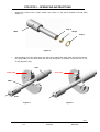
1
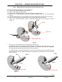
PFD1/PFS1 – OPERATING INSTRUCTIONS
PUMP
PFD1/PFS1
OPERATING INSTRUCTIONS
SAINT-GOBAIN PERFORMANCE PLASTICS ASTI
(Headquarters)
SAINT-GOBAIN PERFORMANCE PLASTICS ASTI
(Factory)
41, boulevard des Bouvets
F-92741 NANTERRE CEDEX
Tel: 33. (0) 1.55.68.59.59
Fax:33. (0) 1.55.68.59.68
E.A.D.A.C. des Berthilliers
F-71850 CHARNAY LES MACON
Tel: 33. (0) 3.85.20.27.00
Fax: 33. (0) 3.85.29.18.48
http://www.astipure.com - http://www.plastics.saint-gobain.com
INDEX
04
DATE
05/07/02
N°
DC01020
PFD1/PFS1 – OPERATING INSTRUCTIONS
INDEX
Page
I – General
I.1 – Introduction
I.2 – Materials
I.3 – Operation description
I.4 – Pump Data
2
II – Quick checklist
II.1 – Shipment
II.2 – Reception
3
III – Installation and operation
III.1 – Testing
III.2 – Set up
III.3 – Connections
III.3.1 – Air/nitrogen connections
III.3.2 – Fluid connections
III.4 – Initial tests and Adjustments
3
IV – Applications
IV.1 – Chemical compatibility
IV.2 – Contamination
IV.3 – Temperature range
IV.4 – Applications
IV.5 – Limitations of use
4
V – Maintenance
V.1 – Trouble shooting
V.2 – Preventive maintenance
V.2.1 – Continuous operation
V.2.2 – Intermittent operation
V.3 – Comments
5
VI – Dismantling and Repair
VI.1 – How to dismantle
VI.2 – Examination
VI.3 – Stripping and assembling the pump
VI.3.1 – Replacing the shuttle valve
VI.3.2 – Replacing the bellows
VI.3.3 – Replacing the central shaft and shaft composite rings
VI.3.4 – Replacing the PTFE sleeves
VI.3.5 – Replacing the bellow and body O.rings
VI.3.6 – Replacing the manifold O.rings
VI.3.7 – Replacing other parts
6
VII – Warranty
11
Appendix:
Spare parts list
Maintenance kits
Section view (drawing “APP 1 REF”)
Part numbers table (“APP 1 REF”)
General arrangement drawing (drawing “APP 1 EXT”)
Flow rate/discharge pressure curves
Pneumatic diagram (drawing “APP 1 CAB”)
INDEX
04
DATE
05/07/02
N°
DC01020
PFD1/PFS1 – OPERATING INSTRUCTIONS
Thank you for selecting a SAINT-GOBAIN PERFORMANCE PLASTICS ASTI model PFD1 AstiPure®
pump, series 2 (or PFS1: slurry applications).
I – General
I.1 – Introduction
The Model PFD/PFS is a pneumatically operated TEFLON® pump. There are no internal or external
metal parts.
The pump is designed for handling corrosive, inflammable and sterile fluids. It meets the
requirements of the semiconductor, pharmaceutical and chemical industries.
I.2 – Materials
All wetted parts are manufactured in TEFLON® PFA HP and PTFE.
Other parts are made of high-tech plastics such as PVDF, PEEK etc.
There are no metal parts.
I.3 – Operation
The pump is pneumatically operated; two bellows joined by a central shaft reciprocate horizontally.
The suction and delivery strokes alternate from one side of the pump to the other.
The pump is self-priming and has four balls, which seat on lip seals (check valves).
The pumping frequency of a bellows pump is much slower than an equivalent diaphragm pump and
results in an extended life for the bellows.
Pulsation dampers with wetted parts in TEFLON® PFA and PTFE are available as an option. This
dampens the pulse by approximately 65 to 80%. The pulsation damper for the PFD1/PFS1 pump is
AMC1/AMS1.
I.4 – Pump Data
Flow rate
Discharge pressure
Suction head
Max. air consumption
Connections
Air connection
Weight
600 L/h (2,5 GPM)
4 bar max. (58 PSI)
3 m water column (10 feet)
10 m³/h (6 SCFM) NTP
10x13 mm or 3/8”x1/2” TEFLON® flared tube or 1/2” MNPT thread.
1/4" I/D gas female thread
Tubing Ø 2,5x4 mm (3/32”x5/32”) maximum
3 m (10 feet) < length < 6 m (20 feet)
2 kg (4,5 lbs)
Also available three larger capacity pumps with optional pulsation dampers:
PFD2/PFS2
Flow rate 20 L/min (5 US GPM)
AMC2/AMS2
PFD3/PFS3
Flow rate 50 L/min (12,5 US GPM)
AMC3/AMS3
PFD4/PFS4
Flow rate 100 L/min (25 US GPM)
AMC4/AMS4
II – Quick checklist
II.1 – Shipment
Pumps are cleaned and assembled in our clean room, then double sealed in plastic bags to ensure
they are not contaminated in transit. They are then packed in cartons with Polyethylene protection.
2/11
INDEX
04
DATE
05/07/02
N°
DC01020
PFD1/PFS1 – OPERATING INSTRUCTIONS
II.2 – Reception
Upon receipt of the pump, please check that:
• The carton has not been damaged in transit. If there is any visible damage, immediately contact
the carrier.
• The pump is not damaged. If there are signs of damage, you should report this immediately to
SGPPL ASTI or your local distributor.
• An operating instruction manual has been included in each package. Please request another copy
if it has not been included.
III – Installation and Operation
III.1 – Testing
All pumps are tested with DI water at the factory in our clean room for:
• Maximum flow rate with no back pressure
• Minimum flow rate with no back pressure
• Flow rate with 4 bar (58 PSI) discharge pressure
• Checked for leakage
III.2 – Set up
The pump must be installed horizontally as shown on general arrangement drawing (see appendix
“APP 1 EXT”). This drawing also shows the overall dimensions of the pump etc.
The pump must be positioned on its feet. If not, the check valves will not seat correctly and the
pump may malfunction.
III.3 – Connections
III.3.1 – Air/Nitrogen connection
The pump must be connected to a clean dry air or nitrogen supply. On no account should the
air/nitrogen supply be lubricated, oil or water droplets will cause the shuttle valve to malfunction.
Minimum and maximum supply pressure must be between 2 and 5 bar (29 and 72,5 PSI).
For optimum pump operation, we recommend a supply pressure of 3,5 bar (51 PSI).
The ID of the tube supplying the dry air/nitrogen should not exceed 2,5 mm (3/32”). The tube length
between the pump and on/off valve should be between 3 m minimum (10 feet) and 6 m maximum
(20 feet).
When in aggressive conditions (acid vapours), it is advised to canalise outlet with a tube of minimum
ID 6 mm (1/4”).
The pneumatic on/off valve must be 3-way to ensure the shuttle valve on the pump resets itself when
the pump is switched off. The flow control valve must be positioned before the 3-way on/off valve
(see appendix “APP 1 CAB”).
A remote control box with on/off switch and needle valve (P/N 21 000 04) is available as an optional
extra.
III.3.2 – Fluid connections
The pump is self-priming. The inlet is at the bottom and the outlet at the top.
Two optional fittings are available:
• PFD1 210 or PFS1 210: pump is supplied with flared fittings suitable for 10x13 mm (3/8”x1/2”)
TEFLON® tube. The tube needs to be flared prior to fitting using SGPPL ASTI forming tool
(P/N MF11013).
• PFD1 221 or PFS1 221: pump is supplied with 1/2” MNPT male threads on the inlet and outlet. We
recommend using TEFLON® tape when connecting female tube fittings to the PFD/S1 221 pump.
3/11
INDEX
04
DATE
05/07/02
N°
DC01020
PFD1/PFS1 – OPERATING INSTRUCTIONS
Both the inlet and outlet fittings can be rotated through 180 degrees if necessary, by loosening the
nuts on the inlet and outlet fittings. Then, retighten the nuts.
III.4 – Initial Tests and Adjustments
Before commissioning the pump, we recommend to test it dry with a supply pressure of 5 bar
(72,5 PSI) to ensure the system works correctly (See III.3.1 for the correct connections).
If the pump is cycling too quickly reduce the speed by adjusting the needle valve.
Before using the pump with chemicals please check:
• The body rings (P/N 2706, Mark L) and manifolds are tight,
• The air/nitrogen supply is dry, clean and between 2 and 5 bar (29 and 72,5 PSI),
• The inlet and outlet fluid connections are correctly fitted and tight.
IV – Applications
IV.1 – Chemical compatibility
All PFD/PFS pump wetted parts are manufactured in TEFLON® PTFE and PFA and are suitable for
pumping even the most corrosive concentrated chemicals: H2SO4, HNO3, HF, H3PO4, HCl, NH4OH,
KOH, NaOH, CH3COOH, TMAH, H2O2...
The viscosity of the liquids must be less than 1000 cpo.
PFD pumps can pump liquids containing particles up to 0,5 mm (0,02").
Very abrasive liquids are not recommended.
Please call either the factory or your local distributor if you require information on chemical
compatibility.
IV.2 – Contamination
The “all plastic” construction of the PFD/PFS pump ensures no ionic contamination of the chemical,
even if there is a bellows failure.
Due to the low frequency and amplitude of the bellows pump, SGPPL ASTI guarantees a lower level
of particle contamination when compared to a diaphragm pump.
IV.3 – Temperature range
The pump can handle liquids from 0°C (32°F) up to +100°C (212°F).
When the fluid temperature is greater than 60°C (140°F) you must frequently check that the body
rings (P/N 2706, Mark L) and manifolds are fully tight and that supply pressure is less than 3 bar
(43,5 PSI).
For special applications call SGPPL ASTI or your local distributor.
IV.4 – Applications
The PFD/PFS pump is a volumetric pump. The stroke volume is dependent on the flow rate and
discharge pressure.
In order to know the precise flow rate of the pump, a paddle wheel flow transmitter can be fitted on
outlet. For PFD1/PFS1 the part number of the flow transmitter is DP11013.
A letter at the end of the part number of your pump indicates that your pump has a special type of
fluid tightness:
• Part number marked K (PFD1 210K or PFS1 210K) indicates that the pump will be supplied with
KALREZ® manifold (P/N 2745K, Mark G) and body O.rings (P/N 2739K, Mark H).
•
Part number marked G (PFD1 210G or PFS1 210G) indicates that the pump will be supplied with
manifolds with no seals (P/N 2559G or 2560G).
4/11
INDEX
04
DATE
05/07/02
N°
DC01020
PFD1/PFS1 – OPERATING INSTRUCTIONS
Important: The absence of letter means that the pump is supplied with standard seals:
• Manifold seals: FEP/Viton O.rings (P/N 2745, Mark G)
• Body seals:
FEP/Viton O.rings (P/N 2739, Mark H)
NB: Other letters exist in our references; they are related to specific options (for instance “F”). Please
contact us for more details.
PFS1 pumps are equipped with valve seats without lip (P/N 2711A, Mark I) and bellows with rounded
spires (P/N 2613S, Mark F) in order to pump abrasive products (slurry).
Common applications are:
• Semiconductor Industry:
•
Transfer of ultrapure and corrosive chemicals.
Pump filter recirculation systems.
Pharmaceuticals and Chemicals: Chemical injection and sampling.
IV.5 – Limitations of use
The standard pumping speed of the PFD1/PFS1 is about 135 strokes/min.
The following should NOT be part of the system:
• Do not connect the pump inlet or outlet with air, nitrogen or liquid under pressure,
• Lubricated and/or wet air/ nitrogen,
• Air supply tubing greater than 2,5 mm (3/32”) ID,
• Air line length between the pump and control valve less than 3 m (10 feet) and more than
6 m (20 feet),
• Air pressure less than 2 bar (29 PSI) or greater than 5 bar (72,5 PSI),
• Inlet connection less than 9 mm (3/8”) ID,
• Restricted suction side (valves, filters...),
• Exceed the recommended liquid temperatures,
• Pumping too viscous or abrasive liquids.
Any of the above may be detrimental to the normal operation and life expectancy of the pump and
may invalidate the warranty.
If the pump is being used with very corrosive chemicals or if it is left for extended periods not in use,
we recommend the system is emptied and flushed.
V – Maintenance
V.1 – Trouble Shooting
If the pump stops for any reason check:
• The air/nitrogen supply,
• That all valves in the chemical lines are open.
Before dismantling the pump, ensure the shuttle valve is in the correct position. Depress the manual
override on the shuttle valve (P/N 2701, Mark A) to re-position the shuttle.
If the pump starts, check that the following was not the cause:
• The air/nitrogen connections (See III.3.1),
• The air/nitrogen quality,
• Has the pump been serviced correctly? (See V.2 Preventive maintenance).
Before dismantling the pump check the following:
• The air/nitrogen supply is “OFF”,
• The chemical and discharge lines are empty and there is no pressure,
• All in line valves are closed,
• You follow your local Health and Safety Regulations with regard to particular chemicals.
5/11
INDEX
DATE
N°
04
05/07/02
DC01020
PFD1/PFS1 – OPERATING INSTRUCTIONS
V.2 – Preventive Maintenance
Important: For “G” pumps, retighten manifold nuts simultaneously and progressively with a
strap wrench in order to ensure a correct tightness.
V.2.1 – Continuous Operation
When the pump is used continuously, it is necessary to replace the following parts every year:
• Shaft composite rings
P/N 7135F
• Central shaft
P/N 2615
Important: these parts should always be replaced together.
During routine maintenance checks, examine the following parts and change them if necessary:
• Bellows
P/N 2613 (PFD) or 2613S (PFS)
• Shuttle valve
P/N 2701
• Viton bellow O.ring
P/N 2725
• Body O.ring
P/N 2739
• Manifold O.ring
P/N 2745
• Lip seal
P/N 2711 (PFD) or 2711A (PFS)
• PTFE sleeves
P/N 7220
• Silencers
P/N 7185
• Ball valves
P/N 2712
V.2.2 – Intermittent operation
If the pump is used intermittently, it is advised to replace all wearing parts every 18 months (shaft
composite rings and central shaft) and to check other parts (bellows, shuttle valve, other seals, lip
seal...).
If the pump is left standing full of chemical for long periods all the Viton O.rings should be replaced.
V.3 – Comments
If the pump is used to pump hot chemicals in excess of 60°C (140°F) the preventive maintenance
schedule time scale should be divided by 2:
• Every 6 months check as for continuous operation,
• Every 9 months check as for intermittent operation.
The above is based on SGPPL ASTI's experience.
SGPPL ASTI cannot be held responsible for premature failures if the pump is misused or
damaged due to an incorrect application.
VI – Dismantling and Repair
Attention: Part numbers quoted in this manual are those used on a “standard” PFD/PFS pump.
Before ordering, please check the spare parts list, the section view of the pump and the part numbers
table (see encl. documents).
VI.1 – How to dismantle
Before dismantling the pump, refer to the Maintenance schedule V.1, and proceed as follows:
• Disconnect the air/nitrogen supply,
• Remove the inlet and outlet connections (beware of any chemical droplets remaining on the
inside),
• Rinse the outside of the pump in DI water to remove all trace of chemicals,
• Remove pump support screws.
6/11
INDEX
04
DATE
05/07/02
N°
DC01020
PFD1/PFS1 – OPERATING INSTRUCTIONS
VI.2 – Examination
To comply with your local Health and Safety Regulations it is essential the pump and all parts are
thoroughly cleaned both on the inside and outside.
See V.2 for the Preventive Maintenance Schedule.
To repair the pump, refer to schedules V.1 and V.2.1.
VI.3 – Stripping and assembling the pump
The SGPPL ASTI design ensures that the pumps are easy to strip and assemble.
The only tools required are a screwdriver to replace the shuttle valve (see VI.3.1) and a strap wrench
to remove body rings (P/N 2706, Mark L). All other items can be removed and replaced by hand. A
tools kit for the whole maintenance is available (P/N KPFD1), as well as maintenance kits (P/N AIR
PFD1, LIQ PFD1, and MEC PFD1), and a preventive maintenance box (P/N PM PFD1, PM PFS1,
PM PFD1G or PM PFS1G). For more details on these kits, please report to appendix documents.
Please refer to drawing “APP 1 REF” to visualize marks and part numbers quoted hereafter.
VI.3.1 – Replacing the shuttle valve
The valve is easily removed from the outside:
1) Unscrew the 2 fastening screws – take care not to damage them,
2) Replace with a new factory assembled shuttle valve (P/N 2701, Mark A),
3) Carefully tighten the 2 fastening screws. Do not overtighten,
4) Test with compressed air/nitrogen. Re-tighten if necessary.
VI.3.2 – Replacing the bellows
To replace the bellows proceed as follows:
1) Remove shuttle valve (see VI.3.1),
2) Unscrew exhaust silencers (P/N 7185),
3) Unscrew the 4 manifold nuts and remove the 4 balls valves (P/N 2712) – take care not to lose
them,
4) Remove the 4 manifold O.rings (P/N 2745, Mark G ), except for PFD/S1…G pumps which are
equipped with manifolds with no seals,
5) Position the pump into a bench vice (tighten only over the core P/N 2708),
6) Unscrew the body ring (P/N 2706, Mark L) with a strap wrench while holding the PFA body,
7) Remove the pump body (P/N 7145 or 7145G, Mark K),
8) Now unscrew the bellows (P/N 2613 or 2613S, Mark F) from the central shaft (P/N 2615,
Mark D),
9) Replace with new bellows – moderately hand tighten,
10) To re-assemble follow the above but in reverse order from 8) to 1). For PFD/S1…G pumps,
retighten manifold nuts simultaneously and progressively with a strap wrench in order to ensure a
correct tightness.
®
All TEFLON PTFE and PFA parts are soft; please handle with care to avoid damage. Do not put
them down on their sealing surfaces.
To re-assemble the PFA bodies, hand tighten the body rings (P/N 2706, Mark L), and block them up
by giving 1/8 further turn with the strap wrench. Check that bodies are well positioned so that
manifolds are tight.
7/11
INDEX
04
DATE
05/07/02
N°
DC01020
PFD1/PFS1 – OPERATING INSTRUCTIONS
VI.3.3 – Replacing the central shaft and shaft composite rings
Follow the same steps described in V1.3.2 until 8) then:
9) Remove the central shaft (P/N 2615, Mark D),
10) Remove the plastic caps (P/N 1028),
11) Remove the C-PEEK plate screws (P/N 2729) and the rings (P/N 1720),
12) Remove the 4 shaft composite rings (P/N 7135F) from plates (P/N 2709 and 2728, Marks B
and C),
13) Clean the plates and the core (P/N 2708) by removing the dust from previous wear by O.rings,
14) Insert 4 new composite rings with tools from our tool kit (P/N KPFD1) as follows:
•
Each of the 4 shaft rings (P/N 7135F) is composed of two parts: one O.ring and one sleeve
(Figure 1):
O.ring
Sleeve
Inner side
7135F
Outer side
Figure 1
•
O.rings can be installed with the O.ring positioning tool P/N 1641.
To install the ring on the inner side of the plate (Figure 2), insert the longer side of the tool in the
plates (P/N 2709 and 2728, Marks B and C), as shown in the drawing. Then place the ring against
the O.ring positioning tool (P/N 1641) and insert it in the groove.
To install the ring on the outer side (Figure 3), insert the shorter side of the O.ring positioning tool
through the inner side of the plate, and place the ring against the positioning tool. Then insert the
ring in its groove.
Long
1641
Short
Short
Long
Inner side
Outer side
Figure 2
Figure 3
8/11
INDEX
04
DATE
05/07/02
N°
DC01020
PFD1/PFS1 – OPERATING INSTRUCTIONS
•
Squeeze the sleeve into a “bean” shape, then insert it in the sleeve insertion tool P/N 2680
(Figure 4):
Step 3
2680
Step 2
Step 1
Figure 4
•
While holding the O.ring positioning tool (P/N 1641) against the plate, place the sleeve insertion
tool (P/N 2680) into the other side and use the push-button to release the sleeve free on the
O.ring (Figures 5 & 6):
1641
Outer side
Inner side
2680
Push
Figure 5
Figure 6
9/11
INDEX
04
DATE
05/07/02
N°
DC01020
PFD1/PFS1 – OPERATING INSTRUCTIONS
•
Use the pick (P/N 1643) to correctly position the sleeve in its groove. Be careful not to damage
the sleeve (Figure 7):
1643
Figure 7
•
Repeat this operation for the 4 sets of rings.
15) Fit the plates and the body rings (P/N 2706, Mark L) on the core (tighten moderately the screws
P/N 2729), insert first the O.ring (P/N 1720) under the screw head,
16) Fit new plastic caps (P/N 1028) so that tightness between the core and the plates is ensured,
17) Important: lightly wipe the central shaft and shaft composite rings with silicon grease (Molykote
111) before re-assembly. Then insert the central shaft without turning it when threaded part
reaches the O.rings,
18) To re-assemble follow the above instructions but in reverse order.
VI.3.4 – Replacing the PTFE sleeves
Follow the same procedure as for VI.3.3 until 14); after replacing the composite rings, remove the
PTFE sleeves (P/N 7220) from the groove with a blunt pointed instrument. Clean and re-assemble
the new part.
A pump that was not originally fitted with PTFE sleeves can be equipped with sleeves. In this case,
you need to change the plates (P/N 2709 and 2728, Marks B and C).
VI.3.5 – Replacing the bellow and body O.rings
After removing the bellows (see V1.3.2, step 8), remove the bellow Viton O.rings (P/N 2725) and the
body O.rings (P/N 2739, Mark H). Then carefully replace the new ones without scratching the
surface of the bellows (P/N 2613 or 2613S, Mark F) or housing (P/N 7145 or 7145G, Mark K).
VI.3.6 – Replacing the manifold O.rings
Follow point VI.3.2, steps 3) and 4). Carefully replace the manifold O.rings (P/N 2745, Mark G). Take
care as these parts are fragile, especially the elbow connectors.
NB: This chapter does not concern PFD/S1…G pumps that have no manifold seals.
10/11
INDEX
04
DATE
05/07/02
N°
DC01020
PFD1/PFS1 – OPERATING INSTRUCTIONS
VI.3.7 – Replacing other parts
When dismantling the pump or control unit for service, components found damaged should
be replaced. Alternatively, the pump/control unit can be returned to your distributor or SGPPL
ASTI for examination, estimate, and repair.
Important: Please indicate what chemical was handled, the frequency of use, and the reason for
returning the pump.
A receipt note “Conditions of use” is at your disposal. Do not hesitate to ask for it when needed.
An estimate for repair will be proposed to you and the pump will be returned to you within one week
from date of its acceptance.
VII – Warranty
SGPPL ASTI pumps and accessories are warranted for all parts and labour against faulty
workmanship (return to factory) for one year from delivery date (9000 hours of use).
SGPPL ASTI is not responsible for damage to its products through improper installation,
maintenance, use or attempts to operate them beyond their mechanical capacity, intentionally or
otherwise, or for unauthorised repair.
SGPPL ASTI shall not be liable for any indirect, special, incidental or consequential damages
resulting from the use, failure or malfunction of any product.
® Teflon and Kalrez Du Pont's registered trademarks
® AstiPure Saint-Gobain Performance Plastics Asti registered trademark
11/11
INDEX
04
DATE
05/07/02
N°
DC01020
PFD1/PFS1 – SPARE PARTS LIST
SAINT-GOBAIN PERFORMANCE PLASTICS ASTI
41 boulevard des Bouvets
F- 92000 NANTERRE
Tel: +33 (0) 1.55.68.59.59
Fax: +33 (0) 1.55.68.59.68
http://www.astipure.com
http://www.plastics.saint-gobain.com
PUMPS PFD1 (SERIES 2) & PFS1
PART
NUMBER
DESIGNATION
QUANTITY
PFD1 . . .
210
221
1028
1720
2559A
2559AZ
2559G
2559GZ
2560A
2560AZ
2560G
2560GZ
2613
2613S
2615
2701
2701F
2706
2706T
2708
2709
2711
2711A
2712
2725
2728
2729
2739
2739K
2745
2745K
7135F
7139
7145
7145G
7185
7220
MS11013
CAP
FLAT PLATE O RING
PFD1 MANIFOLD TUBE 1/2”
PFD1 MANIFOLD TUBE 1/2” ETFE NUTS
PFD1 TG MANIFOLD TUBE 1/2”
PFD1 TG MANIFOLD TUBE 1/2” ETFE NUTS
PFD1 MANIFOLD PIPE THREAD 1/2 MNPT
PFD1 MANIFOLD PIPE THREAD 1/2 MNPT ETFE NUTS
PFD1 TG MANIFOLD PIPE THREAD 1/2 MNPT
PFD1 TG MANIFOLD PIPE THREAD 1/2 MNPT ETFE NUTS
PFD1 BELLOW WITH INSERT
PFS1 BELLOW ROUNDED SPIRES WITH INSERT
CENTRAL SHAFT
SHUTTLE VALVE
SHUTTLE VALVE PE UHMW SHUTTLE
PFD1 BODY RING
PFD1 TEFZEL BODY RING
CORE
BLADED PLATE
PFD1 LIP SEAL
PFS1 SLURRY VALVE SEAT
BALL VALVE Ø 10
VITON BELLOW O.RING
TAPPED PLATE
C-PEEK 5x50 PLATE SCREW
FEP BODY O.RING
KALREZ BODY O.RING
FEP MANIFOLD O.RING
KALREZ MANIFOLD O.RING
SHAFT COMPOSITE O.RING
VITON PNEUMATIC O.RING
PFD1 PFA BODY
PFD1 TG PFA BODY
1/4” EXHAUST SILENCER
PTFE SLEEVE
PVDF NUT TUBING 1/2” OD
INDEX
04
DATE
05/07/02
4
4
2
2
2
2
4
4
2
2
2
2
2
2
1
1
1
2
2
1
1
4
1
1
1
2
2
1
1
4
4
2
1
4
2
2
4
4
4
6
2
2
2
2
2
4
2
1
4
2
2
4
4
4
6
2
2
2
2
2
N°
DC01020
PFS1 . . .
210
221
4
4
2
2
2
2
4
4
2
2
2
2
2
1
1
1
2
2
1
1
2
1
1
1
2
2
1
1
4
4
2
1
4
2
2
4
4
4
6
2
2
2
2
2
4
4
2
1
4
2
2
4
4
4
6
2
2
2
2
2
PFD1/PFS1 – MAINTENANCE KITS
SAINT-GOBAIN PERFORMANCE PLASTICS ASTI
41 boulevard des Bouvets
F- 92000 NANTERRE
Tel : +33 (0)1.55.68.59.59
Fax : +33 (0)1.55.68.59.68
http://www.astipure.com
http://www.plastics.saint-gobain.com
PUMP PFD1 (SERIES 2) – MAINTENANCE KITS
PART
NUMBER
DESIGNATION
QUANTITY
AIR PFD1
1028
1720
2613
2615
2701
2711
2712
2725
2729
2739
2745
7135F
7139
7185
7220
CAP
FLAT PLATE O RING
PFD1 BELLOW WITH INSERT
CENTRAL SHAFT
SHUTTLE VALVE
PFD1 LIP SEAL
BALL VALVE Ø 10
VITON BELLOW O.RING
C-PEEK 5x50 PLATE SCREW
FEP BODY O.RING
FEP MANIFOLD O.RING
SHAFT COMPOSITE O.RING
VITON PNEUMATIC O.RING
1/4” EXHAUST SILENCER
PTFE SLEEVE
LIQ PFD1
MEC PFD1
2
1
1
4
4
2
2
4
4
2
2
PUMPS PFD1 & “PFD1…G” – MAINTENANCE KITS
PART
NUMBER
1028
1720
2613
2615
2701
2711
2712
2725
2729
2739
2745
7135F
7139
7185
7220
DESIGNATION
QUANTITY
CAP
FLAT PLATE O RING
PFD1 BELLOW WITH INSERT
CENTRAL SHAFT
SHUTTLE VALVE
PFD1 LIP SEAL
BALL VALVE Ø 10
VITON BELLOW O.RING
C-PEEK 5x50 PLATE SCREW
FEP BODY O.RING
FEP MANIFOLD O.RING
SHAFT COMPOSITE O.RING
VITON PNEUMATIC O.RING
1/4” EXHAUST SILENCER
PTFE SLEEVE
INDEX
04
DATE
05/07/02
PM PFD1
PM PFD1G
4
2
2
1
1
4
4
2
2
2
4
4
6
2
2
4
2
2
1
1
4
4
2
2
2
N°
DC01020
4
6
2
2
PFD1/PFS1 – MAINTENANCE KITS
SAINT-GOBAIN PERFORMANCE PLASTICS ASTI
41 boulevard des Bouvets
F- 92000 NANTERRE
Tel : +33 (0)1.55.68.59.59
Fax : +33 (0)1.55.68.59.68
http://www.astipure.com
http://www.plastics.saint-gobain.com
PUMPS PFS1 & “PFS1…G” – MAINTENANCE KITS
PART
NUMBER
1028
1720
2613S
2615
2701
2711A
2712
2725
2729
2739
2745
7135F
7139
7185
7220
DESIGNATION
QUANTITY
CAP
FLAT PLATE O RING
PFS1 BELLOW ROUDED SPIRES WITH INSERT
CENTRAL SHAFT
SHUTTLE VALVE
PFS1 SLURRY VALVE SEAT
BALL VALVE Ø 10
VITON BELLOW O.RING
C-PEEK 5x50 PLATE SCREW
FEP BODY O.RING
FEP MANIFOLD O.RING
SHAFT COMPOSITE O.RING
VITON PNEUMATIC O.RING
1/4” EXHAUST SILENCER
PTFE SLEEVE
INDEX
04
DATE
05/07/02
PM PFS1
PM PFS1G
4
2
2
1
1
4
4
2
2
2
4
4
6
2
2
4
2
2
1
1
4
4
2
2
2
N°
DC01020
4
6
2
2
2x E
4x 7135F
2x M
2x L
B
4x 1028
2x 7220
2x 7185
2708
D
C
4x 2712
4x 2729
2 x 2725
4x 1720
4x G
4xI
2x J
2x F
A
6x 7139
2x H
2x K
Dessiné par : j.Be
Vérifié par :
En date du : 24/09/01
En date du :
DESIGNATION
SAINT-GOBAIN PERFORMANCE PLASTICS ASTI
ASTIPURE Pump 1
REFERENCE
APP 1 REF
INDICE
03
TM
41 Boulevard des Bouvets
92000 Nanterre - France
Tel: +33 (0)1 55 68 59 59
Fax: +33 (0)1 55 68 59 68
http://www.astipure.com
PART NUMBERS TABLE
Piloting
PF (standard)
PR
PO
Fluid
D
S
Size
1
1
1
1
1
Connection
Sealing
210
Option
A
B
2701
C
2709
2826
2826
D
2728
2827
2827
E
2615
2828
2828
F
G
2613
H
2745
I
2739
J
2711
K
2559A
L
7145
2706
M
MS11013
2829
2829
2613S
2711A
221
2560A
K
G
2745K
Z
F
2739K
2739
2559G or 2560G
P/N + "Z"
7145G
2706T
2701F
IMPORTANT:
The following reference combination is not relevant:
PO - 1 --- - F
PR
Piloting:
F Standard
R Recirculation
O No piloting
S 1 210 K F
Fluid:
D Standard
S Slurry
Connection:
210 Flare Fitting Ø 10x13 or 3/8"x1/2"
221 Pipe thread Ø 1/2" MNPT
Date: 01/07/02
Index: 03
Option:
Z
TEFZEL nut
F
HF shuttle valve
A:
B:
C:
D:
E:
F:
G:
H:
I:
J:
K:
L:
M:
Shuttle valve
Bladed plate
Tapped plate
Central shaft
Stopper
Bellow
Manifold O.Ring
Body O.Ring
Lip seal
Manifold
Pump body
Body ring
Nut
Sealing:
FEP
K
Kalrez
G
Manifold with no seals
APP 1 REF
26.5mm
1.04"
196mm
7.72"
157mm
6.18"
260.4mm
10.25"
Ø 7mm
.28"
90mm
3.54"
134.8mm
5.31"
120mm
4.72"
Dessiné par: FM
Validé par:
DATE: 02/05/00
SG PPL AST I
DESIGNATION
Pump ASTIPURE 1
REFERENCE
APP 1 EXT
INDICE
00
41 Boulevard des Bouvets
F-92741 Nanterre Cedex
FRANCE
Tel: +33 (0)1 55 68 59 59
Fax: +33 (0)1 55 68 59 68
AstiPure® PFD1 / PFS1 pump flow rate characteristics
4,5
Discharge head (bar)
4
Air supply 5 bar
3,5
3
Air supply 4 bar
2,5
Air supply 3 bar
2
1,5
Air supply 2 bar
1
0,5
0
50
150
250
350
450
Flow rate (l/h)
550
650
750
REFOULEMENT FLUIDE
FLUID OUTLET
Air 2 à 5 Bar
2m Max
VANNE DE REGLAGE
VALVE
VANNE D' ARRET
STOP
Ø2.5x4mm Max - 6m Max
ASPIRATION FLUIDE
FLUID INLET
Dessiné par: FM
Validé par:
DATE: 09/05/00
SG PP L A ST I
DESIGNATION
ASTIPURE Pump 1
REFERENCE
APP 1 CAB
INDICE
00
41 Boulevard des Bouvets
F-92741 Nanterre Cedex
FRANCE
Tel: +33 (0)1 55 68 59 59
Fax: +33 (0)1 55 68 59 68